CN116395055A - A compound spherical robot with wheels and legs - Google Patents
A compound spherical robot with wheels and legsDownload PDFInfo
- Publication number
- CN116395055A CN116395055ACN202310371081.5ACN202310371081ACN116395055ACN 116395055 ACN116395055 ACN 116395055ACN 202310371081 ACN202310371081 ACN 202310371081ACN 116395055 ACN116395055 ACN 116395055A
- Authority
- CN
- China
- Prior art keywords
- leg
- wheel
- frame
- spherical robot
- steering gear
- Prior art date
- Legal status (The legal status is an assumption and is not a legal conclusion. Google has not performed a legal analysis and makes no representation as to the accuracy of the status listed.)
- Pending
Links
- 150000001875compoundsChemical class0.000titleclaimsdescription10
- 230000007246mechanismEffects0.000claimsabstractdescription27
- 239000002131composite materialSubstances0.000claimsabstractdescription14
- 230000005540biological transmissionEffects0.000claimsdescription34
- 230000005484gravityEffects0.000claimsdescription27
- 230000000712assemblyEffects0.000claimsdescription19
- 238000000429assemblyMethods0.000claimsdescription19
- 238000005096rolling processMethods0.000claimsdescription9
- 230000001681protective effectEffects0.000claimsdescription7
- 238000009434installationMethods0.000claimsdescription4
- 230000033001locomotionEffects0.000abstractdescription15
- 230000008901benefitEffects0.000abstractdescription2
- 238000010586diagramMethods0.000description6
- 238000000034methodMethods0.000description2
- 230000007704transitionEffects0.000description2
- 230000009471actionEffects0.000description1
- 230000037147athletic performanceEffects0.000description1
- 230000009193crawlingEffects0.000description1
- 239000000428dustSubstances0.000description1
- 238000005265energy consumptionMethods0.000description1
- 238000005516engineering processMethods0.000description1
- 230000007613environmental effectEffects0.000description1
- 230000006872improvementEffects0.000description1
- 230000008569processEffects0.000description1
Images


Classifications
- B—PERFORMING OPERATIONS; TRANSPORTING
- B62—LAND VEHICLES FOR TRAVELLING OTHERWISE THAN ON RAILS
- B62D—MOTOR VEHICLES; TRAILERS
- B62D57/00—Vehicles characterised by having other propulsion or other ground- engaging means than wheels or endless track, alone or in addition to wheels or endless track
- B62D57/02—Vehicles characterised by having other propulsion or other ground- engaging means than wheels or endless track, alone or in addition to wheels or endless track with ground-engaging propulsion means, e.g. walking members
- B62D57/028—Vehicles characterised by having other propulsion or other ground- engaging means than wheels or endless track, alone or in addition to wheels or endless track with ground-engaging propulsion means, e.g. walking members having wheels and mechanical legs
- B—PERFORMING OPERATIONS; TRANSPORTING
- B62—LAND VEHICLES FOR TRAVELLING OTHERWISE THAN ON RAILS
- B62D—MOTOR VEHICLES; TRAILERS
- B62D57/00—Vehicles characterised by having other propulsion or other ground- engaging means than wheels or endless track, alone or in addition to wheels or endless track
- B62D57/02—Vehicles characterised by having other propulsion or other ground- engaging means than wheels or endless track, alone or in addition to wheels or endless track with ground-engaging propulsion means, e.g. walking members
Landscapes
- Engineering & Computer Science (AREA)
- Chemical & Material Sciences (AREA)
- Combustion & Propulsion (AREA)
- Transportation (AREA)
- Mechanical Engineering (AREA)
- Manipulator (AREA)
Abstract
Description
Translated fromChinese技术领域technical field
本发明涉及移动机器人,尤其涉及一种轮腿复合球形机器人。The invention relates to a mobile robot, in particular to a wheel-leg composite spherical robot.
背景技术Background technique
近年来,随着人类研究领域的不断扩大,移动机器人的作业场景不再局限于结构化环境,这就需要移动机器人具有更强的复杂地形适应能力。现阶段,地面移动机器人按照执行机构的构型主要可分为轮履式、足式、球形、复合型等。其中,单运动模式的移动机器人受限于执行机构的单一,难以适用于复杂的非结构化环境,而具有高适应性的移动复合式机器人成为这一发展趋势的不二选择。In recent years, with the continuous expansion of human research fields, the operating scenarios of mobile robots are no longer limited to structured environments, which requires mobile robots to have stronger adaptability to complex terrain. At this stage, ground mobile robots can be mainly divided into wheel-track type, foot type, spherical type, and composite type according to the configuration of the actuator. Among them, mobile robots with single motion mode are limited by a single actuator, which makes it difficult to apply to complex unstructured environments, and mobile compound robots with high adaptability have become the best choice for this development trend.
目前,常见的球形复合式机器人主要是由球形、腿足式、螺旋翼机器人等互相组合构成,使得球形复合式机器人可在球形姿态下实现滚动运动,变换形式后可实现行走或飞行等。但是,由于球形复合式机器人能实现多种不同的运动模式,其内部驱动数量较多,结构一般都比较复杂,导致内部空间有限,对于轮腿复合的球形机器人来说,必然也使得腿部机构在工作时的伸展空间受限,导致其运动性能下降。At present, the common spherical composite robots are mainly composed of spherical, leg-footed, and screw-wing robots, so that the spherical composite robot can realize rolling motion in a spherical posture, and can walk or fly after changing the form. However, since the spherical composite robot can realize a variety of different motion modes, the number of internal drives is large, and the structure is generally more complicated, resulting in limited internal space. For the wheel-leg composite spherical robot, it is inevitable that the leg mechanism The space for stretching while working is limited, resulting in reduced athletic performance.
发明内容Contents of the invention
本发明所要解决的技术问题是提供一种轮腿复合球形机器人,其简化了球形机器人的内部结构,为腿部机构预留了更大的空间,增加了腿部机构的工作空间,保证了复合球形机器人在不同非结构化环境中的运动性能。The technical problem to be solved by the present invention is to provide a wheel-leg composite spherical robot, which simplifies the internal structure of the spherical robot, reserves more space for the leg mechanism, increases the working space of the leg mechanism, and ensures the composite Motion performance of spherical robots in different unstructured environments.
本发明解决上述技术问题所采用的技术方案为:一种轮腿复合球形机器人,包括骨架和安装架,所述的骨架上套设有滚轮,所述的骨架的两侧固定设置有球面状的壳体,所述的安装架位于所述的壳体内且与所述的壳体相固定,所述的安装架上设置有滚轮驱动机构、方向偏转机构和四个可收缩的腿部组件,四个所述的腿部组件呈前后两两对称设置,当所述的腿部组件处于收缩状态时,所述的腿部组件与所述的壳体、滚轮共同形成一个完整的球面,所述的滚轮驱动机构和所述的方向偏转机构位于所述的骨架内,所述的滚轮驱动机构包括第一电机和三个传动轮,所述的第一电机固定在所述的安装架上,所述的安装架上固定设置有三个沿圆周方向均匀分布的轮腿杆,三个所述的传动轮一一对应的转动连接在所述的轮腿杆的端部,所述的传动轮与所述的滚轮的内表面相抵并撑起所述的滚轮,使得所述的滚轮与所述的骨架不接触,所述的第一电机通过皮带轮组件带动至少两个传动轮转动。The technical solution adopted by the present invention to solve the above technical problems is: a wheel-leg composite spherical robot, including a skeleton and a mounting frame, the skeleton is provided with rollers, and both sides of the skeleton are fixedly provided with spherical The housing, the mounting bracket is located in the housing and fixed to the housing, the mounting bracket is provided with a roller drive mechanism, a direction deflection mechanism and four retractable leg assemblies, four The two leg assemblies are symmetrically arranged in front and back. When the leg assemblies are in the retracted state, the leg assemblies, the housing and the rollers together form a complete spherical surface. The roller driving mechanism and the direction deflection mechanism are located in the frame, the roller driving mechanism includes a first motor and three transmission wheels, the first motor is fixed on the mounting frame, the Three wheel leg rods evenly distributed along the circumferential direction are fixedly arranged on the mounting frame, and the three transmission wheels are connected to the ends of the wheel leg rods in one-to-one correspondence rotation, and the transmission wheel and the The inner surfaces of the rollers contact and prop up the rollers, so that the rollers are not in contact with the frame, and the first motor drives at least two transmission wheels to rotate through the pulley assembly.
进一步地,所述的方向偏转机构包括第二电机、重力架和两个重力块,所述的重力架的上端与所述的安装架相铰接,所述的重力块对称固定在所述的重力架的下端的两侧,所述的第二电机固定安装在所述的重力架上,所述的第二电机的驱动轴上同轴固定设置有主动齿轮,所述的重力架的上端固定设置有传动齿轮,所述的传动齿轮与所述的主动齿轮相啮合,用于驱动所述的重力架产生摆动,所述的重力架的摆动方向与所述的滚轮的滚动方向相垂直。Further, the direction deflection mechanism includes a second motor, a gravity frame and two gravity blocks, the upper end of the gravity frame is hinged to the mounting frame, and the gravity block is symmetrically fixed on the gravity frame. On both sides of the lower end of the frame, the second motor is fixedly mounted on the gravity frame, the drive shaft of the second motor is coaxially fixed with a driving gear, and the upper end of the gravity frame is fixedly arranged There is a transmission gear, the transmission gear meshes with the driving gear, and is used to drive the gravity frame to swing, and the swing direction of the gravity frame is perpendicular to the rolling direction of the rollers.
进一步地,所述的重力架的上端固定设置有传动轴,所述的传动轴与所述的安装架转动连接,所述的传动齿轮与所述的传动轴同轴固定。Further, the upper end of the gravity frame is fixedly provided with a transmission shaft, the transmission shaft is rotatably connected with the installation frame, and the transmission gear is coaxially fixed with the transmission shaft.
进一步地,所述的腿部组件包括支撑腿板、第一舵机、第二舵机、第三舵机和转动架,所述的第一舵机固定在所述的安装架上,所述的转动架与所述的第一舵机的舵盘相固定,所述的第一舵机带动所述的转动架在水平方向转动,所述的第二舵机和第三舵机均固定在所述的转动架上,所述的第二舵机的舵盘上固定设置有第一连杆,所述的第三舵机的舵盘上固定设置有连接座,所述的连接座上铰接有第二连杆,所述的第二连杆位于所述的第一连杆的下方,所述的第一连杆的端部和所述的第二连杆的端部均与所述的支撑腿板相铰接,所述的第一连杆和连接座均在竖直方向转动。Further, the leg assembly includes a supporting leg plate, a first steering gear, a second steering gear, a third steering gear and a turret, the first steering gear is fixed on the mounting frame, and the The turret is fixed to the rudder disc of the first steering gear, the first steering gear drives the turret to rotate in the horizontal direction, and the second steering gear and the third steering gear are fixed on On the turret, the steering wheel of the second steering gear is fixedly provided with a first connecting rod, and the steering wheel of the third steering gear is fixedly provided with a connecting seat, and the connecting seat is hinged There is a second connecting rod, the second connecting rod is located below the first connecting rod, the end of the first connecting rod and the end of the second connecting rod are connected to the The supporting leg boards are hinged, and the first connecting rod and the connecting seat both rotate in the vertical direction.
进一步地,所述的支撑腿板上固定设置有支撑杆,所述的支撑杆的端部转动连接有支撑轮。Further, a support rod is fixedly arranged on the support leg plate, and a support wheel is rotatably connected to the end of the support rod.
进一步地,所述的安装架上固定设置有摄像头,所述的摄像头穿出所述的壳体。Further, a camera is fixedly arranged on the installation frame, and the camera passes through the housing.
进一步地,所述的壳体的外表面固定设置有透明的防护罩,所述的防护罩罩住所述的摄像头。Further, the outer surface of the casing is fixedly provided with a transparent protective cover, and the protective cover covers the camera head.
进一步地,所述的传动轮为橡胶轮。Further, the transmission wheel is a rubber wheel.
与现有技术相比,本发明的优点是:Compared with prior art, the advantage of the present invention is:
(1)、整体结构简单,仅使用两自由度就能实现球形机器人的直线运动和转向运动,为腿部组件预留更大的空间,提升了腿部组件伸展时的工作空间,并保证了复合球形机器人在不同非结构化环境中(如崎岖地形)的运动性能。(1) The overall structure is simple, and only two degrees of freedom can be used to realize the linear motion and steering motion of the spherical robot, reserving more space for the leg components, improving the working space when the leg components are stretched, and ensuring Motion performance of a composite spherical robot in different unstructured environments such as rough terrain.
(2)、四个腿部组件独立控制,可处于不同的伸展状态,通过与方向偏转机构的配合,使得该球形机器人可适用于不同的作业环境,其具有较强的多样化适应能力。(2) The four leg components are independently controlled and can be in different stretching states. Through the cooperation with the direction deflection mechanism, the spherical robot can be applied to different working environments, and it has strong diversified adaptability.
(3)、由于腿部组件上设置有支撑轮,可将其中两个腿部组件伸出并配合滚轮与地面之间形成稳定的三点支撑结构,在该运动模式下,可达到的最大运动速度要远高于一般现有的球形机器人,该过程在结构上近似于单轮机器人向三轮机器人的转变,在运动系统上近似于非完整约束系统至完整约束系统的转变。(3) Since there are support wheels on the leg components, two of the leg components can be stretched out to form a stable three-point support structure between the rollers and the ground. In this exercise mode, the maximum movement that can be achieved The speed is much higher than that of general existing spherical robots. The process is structurally similar to the transition from a single-wheeled robot to a three-wheeled robot, and similar to the transition from a non-holonomic constrained system to a holonomic constrained system in terms of motion system.
附图说明Description of drawings
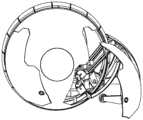
图1为本发明在腿部组件全部收缩时的立体结构示意图;Fig. 1 is the schematic diagram of the three-dimensional structure of the present invention when the leg components are fully contracted;
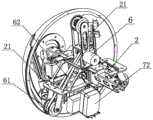
图2为图1去掉壳体和防护罩后的内部结构示意图;Fig. 2 is a schematic diagram of the internal structure of Fig. 1 after removing the housing and the protective cover;
图3为本发明的腿部组件在伸展状态时的结构示意图;Fig. 3 is a schematic structural view of the leg assembly of the present invention in an extended state;
图4为本发明的滚轮驱动机构的结构示意图;Fig. 4 is a schematic structural view of the roller drive mechanism of the present invention;
图5为本发明的方向偏转机构的结构示意图;Fig. 5 is a structural schematic diagram of the direction deflection mechanism of the present invention;
图6为本发明的工作状态示意图之一;Fig. 6 is one of working status schematic diagrams of the present invention;
图7为本发明的工作状态示意图之二;Fig. 7 is the second schematic diagram of the working state of the present invention;
图8为本发明的工作状态示意图之三。Fig. 8 is the third schematic diagram of the working state of the present invention.
实施方式Implementation
以下结合附图实施例对本发明作进一步详细描述。The present invention will be further described in detail below in conjunction with the accompanying drawings and embodiments.
如图所示,一种轮腿复合球形机器人,包括骨架1和安装架2,骨架1上套设有滚轮3,骨架1的两侧通过螺钉固定连接有球面状的壳体4,安装架2位于壳体4内且与壳体4相固定,安装架2上设置有滚轮驱动机构、方向偏转机构和四个可收缩的腿部组件5,四个腿部组件5呈前后两两对称设置,腿部组件5包括支撑腿板51、第一舵机52、第二舵机53、第三舵机54和转动架55,第一舵机52固定在安装架2上,转动架55与第一舵机52的舵盘相固定,第一舵机52带动转动架55在水平方向转动,第二舵机53和第三舵机54均固定在转动架55上,第二舵机53的舵盘上固定设置有第一连杆57,第三舵机54的舵盘上固定设置有连接座58,连接座58上铰接有第二连杆59,第二连杆59位于第一连杆57的下方,第一连杆57的端部和第二连杆59的端部均与支撑腿板51相铰接,第一连杆57和连接座58均在竖直方向转动,支撑腿板51上固定设置有支撑杆50,支撑杆50的端部转动连接有支撑轮501,当腿部组件处于收缩状态时,支撑腿板51与壳体4、滚轮3共同形成一个完整的球面,滚轮驱动机构和方向偏转机构位于骨架1内,滚轮驱动机构包括第一电机6和三个传动轮61,第一电机6固定在安装架2上,安装架2上固定设置有三个沿圆周方向均匀分布的轮腿杆21,三个传动轮61一一对应的转动连接在轮腿杆21的端部,传动轮61为橡胶轮,传动轮61与滚轮3的内表面相抵并撑起滚轮3,使得滚轮3与骨架1不接触,第一电机6通过皮带轮组件62同时带动至少两个传动轮61转动;方向偏转机构包括第二电机7、重力架71和两个重力块72,重力架71的上端固定设置有传动轴(图中未标出),传动轴与安装架2转动连接,两个重力块72对称固定在重力架71的下端的两侧,第二电机7固定安装在重力架71上,第二电机7的驱动轴上同轴固定设置有主动齿轮73,传动轴上同轴固定有传动齿轮74,传动齿轮74与主动齿轮73相啮合,用于驱动重力架71产生摆动,重力架71的摆动方向与滚轮3的滚动方向相垂直。As shown in the figure, a compound spherical robot with wheels and legs includes a
上述实施例中,为了便于机器人采集周边的环境信息,还可在安装架2上固定设置有摄像头8,摄像头8穿出壳体4,壳体4的外表面固定设置有透明的防护罩9,防护罩9罩住摄像头8,以防止摄像头8沾染灰尘,保证图像采集的清晰度,同时也避免摄像头受到碰撞而被损坏。In the above embodiment, in order to facilitate the robot to collect surrounding environmental information, a
本发明的轮腿复合球形机器人在不同非结构化环境中的工作状态为:The working state of the wheel-leg composite spherical robot in different unstructured environments is:
(1)、当球形机器人处于平坦地形时,可控制四个腿部组件5均处于收缩状态,如图1所示,即采用球形滚动模式,其运动效率高、能耗低;也可控制后部的两个腿部组件5伸出,并使支撑轮501着地,如图6所示,两个支撑轮501沿滚轮3对称,使球形机器人处于稳定的三轮支撑模式,以提高其运动速度。(1) When the spherical robot is on a flat terrain, it can control the four
其中,滚轮3的滚动通过第一电机6带动传动轮61转动,传动轮61通过摩擦力带动滚轮3转动,实现球形机器人的前行或后退。而当需要控制腿部组件5伸出时,第二舵机53和第三舵机54分别带动第一连杆57和第二连杆59转动,使支撑腿板51向壳体4外部伸出同时控制好支撑腿板51相对地面的角度,使支撑轮501着地或支撑腿板51直接着地。而通过第一舵机52可控制整个腿部组件5伸出时在水平方向的转动角度,或者控制两个腿部组件5之间的角度。Wherein, the rolling of the
此外,当球形机器人处于球形滚动模式时,通过第二电机7带动重力架71偏转,即机器人整体的重心发生偏转实现球形机器人的转向。而当球形机器人处于三轮支撑模式时,控制后部两个腿部组件5在水平方向向同一方向转动相同的角度即可实现转向。In addition, when the spherical robot is in the spherical rolling mode, the
(2)、当球形机器人处于较为崎岖的地形时,可控制四个腿部组件5均处于伸出状态,且使支撑腿板51着地,如图8所示,即采用四足爬行模式,其地形适应能力强。而且该模式下可以通过依次控制不同的腿部组件5在水平方向与竖直方向的转动角度来实现转向。(2) When the spherical robot is in a relatively rough terrain, it can control the four
(3)、当球形机器人处于较为陡峭的坡面时,控制后部的两个腿部组件5伸出,并使支撑轮501着地,如图6所示,使球形机器人处于三轮支撑模式。(3) When the spherical robot is on a relatively steep slope, control the two rear leg assemblies 5 to stretch out, and make the
(4)、当球形机器人需要跨越高度较低的小台阶时,控制后部的两个腿部组件5向后伸出,并使支撑腿板51着地,如图7所示,然后在控制滚轮3滚动时,两个腿部组件5给壳体施加斜向上的推力,同时第二电机7工作,使壳体发生偏转,在三者的共同作用下实现对小台阶的跨越。(4), when the spherical robot needs to cross a small step with a low height, control the two rear leg assemblies 5 to stretch out backward, and make the supporting
(5)、当球形机器人需要跨越高度较高的大台阶时,控制四个腿部组件5均伸出壳体4,位于后部的两个腿部组件的支撑腿板51着地,位于前部的两个腿部组件5的支撑腿板51或支撑轮501跨越在大台阶上,然后控制滚轮3滚动,实现对大台阶的跨越。(5) When the spherical robot needs to cross a large step with a high height, the four
本发明的保护范围包括但不限于以上实施方式,其保护范围以权利要求书为准,任何对本技术做出的本领域的技术人员容易想到的替换、变形、改进均落入本发明的保护范围。The scope of protection of the present invention includes but is not limited to the above embodiments, and the scope of protection is based on the claims. Any replacement, deformation, and improvement made to the technology that are easily conceived by those skilled in the art all fall within the scope of protection of the present invention .
Claims (8)
Translated fromChinesePriority Applications (1)
| Application Number | Priority Date | Filing Date | Title |
|---|---|---|---|
| CN202310371081.5ACN116395055A (en) | 2023-04-07 | 2023-04-07 | A compound spherical robot with wheels and legs |
Applications Claiming Priority (1)
| Application Number | Priority Date | Filing Date | Title |
|---|---|---|---|
| CN202310371081.5ACN116395055A (en) | 2023-04-07 | 2023-04-07 | A compound spherical robot with wheels and legs |
Publications (1)
| Publication Number | Publication Date |
|---|---|
| CN116395055Atrue CN116395055A (en) | 2023-07-07 |
Family
ID=87008598
Family Applications (1)
| Application Number | Title | Priority Date | Filing Date |
|---|---|---|---|
| CN202310371081.5APendingCN116395055A (en) | 2023-04-07 | 2023-04-07 | A compound spherical robot with wheels and legs |
Country Status (1)
| Country | Link |
|---|---|
| CN (1) | CN116395055A (en) |
Cited By (1)
| Publication number | Priority date | Publication date | Assignee | Title |
|---|---|---|---|---|
| CN117340887A (en)* | 2023-11-16 | 2024-01-05 | 泰州学院 | A computer remotely operated robot |
Citations (9)
| Publication number | Priority date | Publication date | Assignee | Title |
|---|---|---|---|---|
| CN102267505A (en)* | 2011-06-29 | 2011-12-07 | 北京航空航天大学 | Portable telescopic spherical throwing detection robot |
| KR20110139912A (en)* | 2010-06-24 | 2011-12-30 | 한국과학기술원 | Throwing Reconnaissance Robot with Omnidirectional Shock Absorption Mechanism |
| CN103231745A (en)* | 2013-04-28 | 2013-08-07 | 上海大学 | Five-drive spherical robot using mixed synchronous belt |
| KR20140072740A (en)* | 2012-12-05 | 2014-06-13 | 경북대학교 산학협력단 | Spherical robot using thrust |
| CN105480316A (en)* | 2016-01-11 | 2016-04-13 | 佛山市南海区广工大数控装备协同创新研究院 | Spherical robot capable of realizing omnidirectional movement |
| CN205466241U (en)* | 2016-03-15 | 2016-08-17 | 郑州大学 | Can get into robot of work area fast |
| CN110576917A (en)* | 2019-08-23 | 2019-12-17 | 河海大学常州校区 | A tumbling bionic eight-legged robot |
| CN212980384U (en)* | 2020-05-18 | 2021-04-16 | 华东理工大学 | Wheel-foot composite robot |
| CN216761962U (en)* | 2022-03-09 | 2022-06-17 | 西南交通大学 | Robot with multi-foot and rolling double-motion mode |
- 2023
- 2023-04-07CNCN202310371081.5Apatent/CN116395055A/enactivePending
Patent Citations (9)
| Publication number | Priority date | Publication date | Assignee | Title |
|---|---|---|---|---|
| KR20110139912A (en)* | 2010-06-24 | 2011-12-30 | 한국과학기술원 | Throwing Reconnaissance Robot with Omnidirectional Shock Absorption Mechanism |
| CN102267505A (en)* | 2011-06-29 | 2011-12-07 | 北京航空航天大学 | Portable telescopic spherical throwing detection robot |
| KR20140072740A (en)* | 2012-12-05 | 2014-06-13 | 경북대학교 산학협력단 | Spherical robot using thrust |
| CN103231745A (en)* | 2013-04-28 | 2013-08-07 | 上海大学 | Five-drive spherical robot using mixed synchronous belt |
| CN105480316A (en)* | 2016-01-11 | 2016-04-13 | 佛山市南海区广工大数控装备协同创新研究院 | Spherical robot capable of realizing omnidirectional movement |
| CN205466241U (en)* | 2016-03-15 | 2016-08-17 | 郑州大学 | Can get into robot of work area fast |
| CN110576917A (en)* | 2019-08-23 | 2019-12-17 | 河海大学常州校区 | A tumbling bionic eight-legged robot |
| CN212980384U (en)* | 2020-05-18 | 2021-04-16 | 华东理工大学 | Wheel-foot composite robot |
| CN216761962U (en)* | 2022-03-09 | 2022-06-17 | 西南交通大学 | Robot with multi-foot and rolling double-motion mode |
Cited By (2)
| Publication number | Priority date | Publication date | Assignee | Title |
|---|---|---|---|---|
| CN117340887A (en)* | 2023-11-16 | 2024-01-05 | 泰州学院 | A computer remotely operated robot |
| CN117340887B (en)* | 2023-11-16 | 2024-05-17 | 泰州学院 | Computer remote operation robot |
Similar Documents
| Publication | Publication Date | Title |
|---|---|---|
| CN113247138B (en) | Multi-motion mode wheel-leg separation quadruped robot | |
| CN105383586B (en) | Crawler leg composite movable robot | |
| CN111391934B (en) | Wheel-leg composite robot moving device and wheel-leg composite robot | |
| CN104002888B (en) | A kind of snake-shaped robot based on quadrangular mechanism | |
| CN110077486B (en) | A bionic eight-legged special robot | |
| CN116395055A (en) | A compound spherical robot with wheels and legs | |
| CN111993389A (en) | Hybrid-driven movable multi-degree-of-freedom parallel motion platform | |
| CN114275071A (en) | Novel deformable wheel-leg robot | |
| CN112849300A (en) | Multi-mode deformable wheel type moving mechanism | |
| CN210881671U (en) | Wheeled mobile robot walking chassis | |
| CN113428257B (en) | Six-foot platform of reconfigurable space closed-chain leg mechanism | |
| CN110239637B (en) | A wheel track switchable omnidirectional mobile chassis | |
| CN209757307U (en) | A Lifting Mechanism for Cellular Unmanned Ground Mobile System | |
| CN113715569B (en) | Amphibious robot and control method thereof | |
| CN206766183U (en) | A kind of six sufficient mobile platform of double-deck disc type | |
| CN114633823B (en) | Triphibian robot | |
| CN105599817B (en) | A kind of ball shape robot for possessing skip capability | |
| CN205652230U (en) | Spherical robot drive mechanism | |
| CN115556123A (en) | A remote computer controlled robot | |
| CN112810718B (en) | Stair climbing wheel set and stair climbing robot comprising same | |
| CN115303383A (en) | Walking robot based on novel cam walking mechanism | |
| CN217146196U (en) | Wheel-legged multi-degree-of-freedom leg structure for robots based on metamorphosis principle | |
| CN105905177B (en) | Spherical robot driving mechanism | |
| CN220639403U (en) | A wheel assembly capable of overcoming obstacles | |
| CN215706765U (en) | An all-terrain four-link obstacle crossing robot |
Legal Events
| Date | Code | Title | Description |
|---|---|---|---|
| PB01 | Publication | ||
| PB01 | Publication | ||
| SE01 | Entry into force of request for substantive examination | ||
| SE01 | Entry into force of request for substantive examination |