CN116370749A - Devices for infusion of fluids - Google Patents
Devices for infusion of fluidsDownload PDFInfo
- Publication number
- CN116370749A CN116370749ACN202310267643.1ACN202310267643ACN116370749ACN 116370749 ACN116370749 ACN 116370749ACN 202310267643 ACN202310267643 ACN 202310267643ACN 116370749 ACN116370749 ACN 116370749A
- Authority
- CN
- China
- Prior art keywords
- pump
- tube
- plunger
- processor
- fluid
- Prior art date
- Legal status (The legal status is an assumption and is not a legal conclusion. Google has not performed a legal analysis and makes no representation as to the accuracy of the status listed.)
- Pending
Links
- 239000012530fluidSubstances0.000titleclaimsabstractdescription603
- 238000001802infusionMethods0.000titleclaimsabstractdescription403
- 230000007246mechanismEffects0.000claimsabstractdescription135
- 238000005086pumpingMethods0.000claimsabstractdescription115
- 230000002572peristaltic effectEffects0.000claimsdescription225
- 238000005259measurementMethods0.000claimsdescription190
- 239000007788liquidSubstances0.000claimsdescription87
- 238000012544monitoring processMethods0.000claimsdescription63
- 238000004891communicationMethods0.000claimsdescription49
- 230000008859changeEffects0.000claimsdescription48
- 238000011144upstream manufacturingMethods0.000claimsdescription48
- 230000000903blocking effectEffects0.000claimsdescription39
- 239000000463materialSubstances0.000claimsdescription37
- 230000000694effectsEffects0.000claimsdescription25
- 238000007906compressionMethods0.000claimsdescription14
- 230000006835compressionEffects0.000claimsdescription14
- 238000012545processingMethods0.000claimsdescription12
- 238000009826distributionMethods0.000claimsdescription8
- 230000035939shockEffects0.000claimsdescription6
- 238000001228spectrumMethods0.000claimsdescription6
- 239000006096absorbing agentSubstances0.000claimsdescription5
- 230000010287polarizationEffects0.000claimsdescription4
- 238000010168coupling processMethods0.000claimsdescription3
- 239000002245particleSubstances0.000claimsdescription3
- 230000008878couplingEffects0.000claimsdescription2
- 238000005859coupling reactionMethods0.000claimsdescription2
- 238000007872degassingMethods0.000claimsdescription2
- 238000000034methodMethods0.000description241
- 239000003570airSubstances0.000description144
- 239000012528membraneSubstances0.000description110
- 239000003814drugSubstances0.000description105
- 229940079593drugDrugs0.000description101
- 230000008569processEffects0.000description81
- 230000003287optical effectEffects0.000description80
- 238000010586diagramMethods0.000description64
- 230000006870functionEffects0.000description64
- 238000004422calculation algorithmMethods0.000description63
- 230000008595infiltrationEffects0.000description55
- 238000001764infiltrationMethods0.000description55
- 238000001514detection methodMethods0.000description52
- 239000008280bloodSubstances0.000description50
- 210000004369bloodAnatomy0.000description50
- 230000004044responseEffects0.000description45
- 238000012360testing methodMethods0.000description45
- 238000012546transferMethods0.000description42
- 230000000875corresponding effectEffects0.000description39
- 230000009471actionEffects0.000description28
- 238000011282treatmentMethods0.000description22
- 230000001276controlling effectEffects0.000description21
- 239000010408filmSubstances0.000description21
- 230000007704transitionEffects0.000description21
- 230000008901benefitEffects0.000description20
- 239000011159matrix materialSubstances0.000description19
- 238000011049fillingMethods0.000description18
- 229920003023plasticPolymers0.000description17
- 210000004072lungAnatomy0.000description16
- 239000004033plasticSubstances0.000description16
- 239000004417polycarbonateSubstances0.000description16
- 230000001105regulatory effectEffects0.000description16
- 230000005355Hall effectEffects0.000description15
- 238000003708edge detectionMethods0.000description15
- 238000003384imaging methodMethods0.000description15
- 238000007726management methodMethods0.000description15
- 230000014509gene expressionEffects0.000description14
- 229910052751metalInorganic materials0.000description14
- 239000002184metalSubstances0.000description14
- 229940126701oral medicationDrugs0.000description14
- 239000000872bufferSubstances0.000description11
- 230000001419dependent effectEffects0.000description11
- 238000005286illuminationMethods0.000description11
- 238000007789sealingMethods0.000description11
- 230000035945sensitivityEffects0.000description10
- 210000003462veinAnatomy0.000description10
- 238000009530blood pressure measurementMethods0.000description9
- 238000006073displacement reactionMethods0.000description9
- 239000013598vectorSubstances0.000description9
- 238000010521absorption reactionMethods0.000description8
- 239000012080ambient airSubstances0.000description8
- 230000000712assemblyEffects0.000description8
- 238000000429assemblyMethods0.000description8
- 238000013461designMethods0.000description8
- 239000003921oilSubstances0.000description8
- 102000001554HemoglobinsHuman genes0.000description7
- 108010054147HemoglobinsProteins0.000description7
- 238000000576coating methodMethods0.000description7
- 238000009833condensationMethods0.000description7
- 230000005494condensationEffects0.000description7
- 238000012790confirmationMethods0.000description7
- 230000000670limiting effectEffects0.000description7
- 230000003068static effectEffects0.000description7
- 230000001960triggered effectEffects0.000description7
- XLYOFNOQVPJJNP-UHFFFAOYSA-NwaterSubstancesOXLYOFNOQVPJJNP-UHFFFAOYSA-N0.000description7
- HTTJABKRGRZYRN-UHFFFAOYSA-NHeparinChemical compoundOC1C(NC(=O)C)C(O)OC(COS(O)(=O)=O)C1OC1C(OS(O)(=O)=O)C(O)C(OC2C(C(OS(O)(=O)=O)C(OC3C(C(O)C(O)C(O3)C(O)=O)OS(O)(=O)=O)C(CO)O2)NS(O)(=O)=O)C(C(O)=O)O1HTTJABKRGRZYRN-UHFFFAOYSA-N0.000description6
- 101001121408Homo sapiens L-amino-acid oxidaseProteins0.000description6
- 102100026388L-amino-acid oxidaseHuman genes0.000description6
- 230000006399behaviorEffects0.000description6
- 238000004364calculation methodMethods0.000description6
- 239000011248coating agentSubstances0.000description6
- 230000007423decreaseEffects0.000description6
- 238000007599dischargingMethods0.000description6
- 239000006260foamSubstances0.000description6
- 229960002897heparinDrugs0.000description6
- 229920000669heparinPolymers0.000description6
- 230000001965increasing effectEffects0.000description6
- NOESYZHRGYRDHS-UHFFFAOYSA-NinsulinChemical compoundN1C(=O)C(NC(=O)C(CCC(N)=O)NC(=O)C(CCC(O)=O)NC(=O)C(C(C)C)NC(=O)C(NC(=O)CN)C(C)CC)CSSCC(C(NC(CO)C(=O)NC(CC(C)C)C(=O)NC(CC=2C=CC(O)=CC=2)C(=O)NC(CCC(N)=O)C(=O)NC(CC(C)C)C(=O)NC(CCC(O)=O)C(=O)NC(CC(N)=O)C(=O)NC(CC=2C=CC(O)=CC=2)C(=O)NC(CSSCC(NC(=O)C(C(C)C)NC(=O)C(CC(C)C)NC(=O)C(CC=2C=CC(O)=CC=2)NC(=O)C(CC(C)C)NC(=O)C(C)NC(=O)C(CCC(O)=O)NC(=O)C(C(C)C)NC(=O)C(CC(C)C)NC(=O)C(CC=2NC=NC=2)NC(=O)C(CO)NC(=O)CNC2=O)C(=O)NCC(=O)NC(CCC(O)=O)C(=O)NC(CCCNC(N)=N)C(=O)NCC(=O)NC(CC=3C=CC=CC=3)C(=O)NC(CC=3C=CC=CC=3)C(=O)NC(CC=3C=CC(O)=CC=3)C(=O)NC(C(C)O)C(=O)N3C(CCC3)C(=O)NC(CCCCN)C(=O)NC(C)C(O)=O)C(=O)NC(CC(N)=O)C(O)=O)=O)NC(=O)C(C(C)CC)NC(=O)C(CO)NC(=O)C(C(C)O)NC(=O)C1CSSCC2NC(=O)C(CC(C)C)NC(=O)C(NC(=O)C(CCC(N)=O)NC(=O)C(CC(N)=O)NC(=O)C(NC(=O)C(N)CC=1C=CC=CC=1)C(C)C)CC1=CN=CN1NOESYZHRGYRDHS-UHFFFAOYSA-N0.000description6
- 230000003993interactionEffects0.000description6
- 238000004519manufacturing processMethods0.000description6
- 230000000737periodic effectEffects0.000description6
- 230000002829reductive effectEffects0.000description6
- 238000005070samplingMethods0.000description6
- 239000004677NylonSubstances0.000description5
- 239000003990capacitorSubstances0.000description5
- 238000006243chemical reactionMethods0.000description5
- 230000002596correlated effectEffects0.000description5
- 238000001914filtrationMethods0.000description5
- 238000011068loading methodMethods0.000description5
- 238000002483medicationMethods0.000description5
- 229920001778nylonPolymers0.000description5
- 238000003825pressingMethods0.000description5
- 230000002441reversible effectEffects0.000description5
- 238000010183spectrum analysisMethods0.000description5
- 238000004448titrationMethods0.000description5
- 230000000007visual effectEffects0.000description5
- 230000015572biosynthetic processEffects0.000description4
- 239000003795chemical substances by applicationSubstances0.000description4
- 239000002131composite materialSubstances0.000description4
- 238000013016dampingMethods0.000description4
- VYFYYTLLBUKUHU-UHFFFAOYSA-NdopamineChemical compoundNCCC1=CC=C(O)C(O)=C1VYFYYTLLBUKUHU-UHFFFAOYSA-N0.000description4
- 229920001971elastomerPolymers0.000description4
- 239000000806elastomerSubstances0.000description4
- 238000002079electron magnetic resonance spectroscopyMethods0.000description4
- 230000005284excitationEffects0.000description4
- 238000009499grossingMethods0.000description4
- 238000002329infrared spectrumMethods0.000description4
- 239000006187pillSubstances0.000description4
- 239000002985plastic filmSubstances0.000description4
- 238000010926purgeMethods0.000description4
- 238000011084recoveryMethods0.000description4
- 230000009467reductionEffects0.000description4
- 238000005096rolling processMethods0.000description4
- 230000003595spectral effectEffects0.000description4
- 230000001360synchronised effectEffects0.000description4
- 238000003786synthesis reactionMethods0.000description4
- 238000002560therapeutic procedureMethods0.000description4
- 102000004877InsulinHuman genes0.000description3
- 108090001061InsulinProteins0.000description3
- 241000405070PercophidaeSpecies0.000description3
- 101100012902Saccharomyces cerevisiae (strain ATCC 204508 / S288c) FIG2 geneProteins0.000description3
- 108010059993VancomycinProteins0.000description3
- 239000000853adhesiveSubstances0.000description3
- 230000001070adhesive effectEffects0.000description3
- 229910052782aluminiumInorganic materials0.000description3
- XAGFODPZIPBFFR-UHFFFAOYSA-NaluminiumChemical compound[Al]XAGFODPZIPBFFR-UHFFFAOYSA-N0.000description3
- 238000004458analytical methodMethods0.000description3
- 230000004888barrier functionEffects0.000description3
- BJQHLKABXJIVAM-UHFFFAOYSA-Nbis(2-ethylhexyl) phthalateChemical compoundCCCCC(CC)COC(=O)C1=CC=CC=C1C(=O)OCC(CC)CCCCBJQHLKABXJIVAM-UHFFFAOYSA-N0.000description3
- 238000012937correctionMethods0.000description3
- 230000001066destructive effectEffects0.000description3
- 238000005516engineering processMethods0.000description3
- 238000009434installationMethods0.000description3
- 229940125396insulinDrugs0.000description3
- 239000000203mixtureSubstances0.000description3
- 238000012986modificationMethods0.000description3
- 230000004048modificationEffects0.000description3
- 230000036961partial effectEffects0.000description3
- 230000035515penetrationEffects0.000description3
- 229920001343polytetrafluoroethylenePolymers0.000description3
- 239000004810polytetrafluoroethyleneSubstances0.000description3
- 239000011148porous materialSubstances0.000description3
- 230000001902propagating effectEffects0.000description3
- 230000004224protectionEffects0.000description3
- 238000012552reviewMethods0.000description3
- 239000007787solidSubstances0.000description3
- 238000003860storageMethods0.000description3
- 230000001225therapeutic effectEffects0.000description3
- 229960003165vancomycinDrugs0.000description3
- MYPYJXKWCTUITO-LYRMYLQWSA-NvancomycinChemical compoundO([C@@H]1[C@@H](O)[C@H](O)[C@@H](CO)O[C@H]1OC1=C2C=C3C=C1OC1=CC=C(C=C1Cl)[C@@H](O)[C@H](C(N[C@@H](CC(N)=O)C(=O)N[C@H]3C(=O)N[C@H]1C(=O)N[C@H](C(N[C@@H](C3=CC(O)=CC(O)=C3C=3C(O)=CC=C1C=3)C(O)=O)=O)[C@H](O)C1=CC=C(C(=C1)Cl)O2)=O)NC(=O)[C@@H](CC(C)C)NC)[C@H]1C[C@](C)(N)[C@H](O)[C@H](C)O1MYPYJXKWCTUITO-LYRMYLQWSA-N0.000description3
- MYPYJXKWCTUITO-UHFFFAOYSA-NvancomycinNatural productsO1C(C(=C2)Cl)=CC=C2C(O)C(C(NC(C2=CC(O)=CC(O)=C2C=2C(O)=CC=C3C=2)C(O)=O)=O)NC(=O)C3NC(=O)C2NC(=O)C(CC(N)=O)NC(=O)C(NC(=O)C(CC(C)C)NC)C(O)C(C=C3Cl)=CC=C3OC3=CC2=CC1=C3OC1OC(CO)C(O)C(O)C1OC1CC(C)(N)C(O)C(C)O1MYPYJXKWCTUITO-UHFFFAOYSA-N0.000description3
- 238000003466weldingMethods0.000description3
- 238000004804windingMethods0.000description3
- SFLSHLFXELFNJZ-QMMMGPOBSA-N(-)-norepinephrineChemical compoundNC[C@H](O)C1=CC=C(O)C(O)=C1SFLSHLFXELFNJZ-QMMMGPOBSA-N0.000description2
- WKBPZYKAUNRMKP-UHFFFAOYSA-N1-[2-(2,4-dichlorophenyl)pentyl]1,2,4-triazoleChemical compoundC=1C=C(Cl)C=C(Cl)C=1C(CCC)CN1C=NC=N1WKBPZYKAUNRMKP-UHFFFAOYSA-N0.000description2
- RYGMFSIKBFXOCR-UHFFFAOYSA-NCopperChemical compound[Cu]RYGMFSIKBFXOCR-UHFFFAOYSA-N0.000description2
- 239000004803Di-2ethylhexylphthalateSubstances0.000description2
- 101000827703Homo sapiens Polyphosphoinositide phosphataseProteins0.000description2
- 102100023591Polyphosphoinositide phosphataseHuman genes0.000description2
- -1SarlinkPolymers0.000description2
- FAPWRFPIFSIZLT-UHFFFAOYSA-MSodium chlorideChemical compound[Na+].[Cl-]FAPWRFPIFSIZLT-UHFFFAOYSA-M0.000description2
- 239000012298atmosphereSubstances0.000description2
- 230000002238attenuated effectEffects0.000description2
- 230000003542behavioural effectEffects0.000description2
- 230000037396body weightEffects0.000description2
- 239000000919ceramicSubstances0.000description2
- 239000003086colorantSubstances0.000description2
- 230000000295complement effectEffects0.000description2
- 229910052802copperInorganic materials0.000description2
- 239000010949copperSubstances0.000description2
- 230000001934delayEffects0.000description2
- 238000011161developmentMethods0.000description2
- 229960003638dopamineDrugs0.000description2
- 239000013013elastic materialSubstances0.000description2
- 230000005484gravityEffects0.000description2
- 230000003760hair shineEffects0.000description2
- 230000002209hydrophobic effectEffects0.000description2
- 239000003978infusion fluidSubstances0.000description2
- 239000004973liquid crystal related substanceSubstances0.000description2
- 230000007257malfunctionEffects0.000description2
- 229960002748norepinephrineDrugs0.000description2
- SFLSHLFXELFNJZ-UHFFFAOYSA-NnorepinephrineNatural productsNCC(O)C1=CC=C(O)C(O)=C1SFLSHLFXELFNJZ-UHFFFAOYSA-N0.000description2
- 230000005019pattern of movementEffects0.000description2
- 230000002093peripheral effectEffects0.000description2
- 230000010363phase shiftEffects0.000description2
- 229920000515polycarbonatePolymers0.000description2
- 230000002265preventionEffects0.000description2
- 230000000246remedial effectEffects0.000description2
- 230000000284resting effectEffects0.000description2
- 238000004513sizingMethods0.000description2
- 210000004872soft tissueAnatomy0.000description2
- 239000000243solutionSubstances0.000description2
- 239000007921spraySubstances0.000description2
- 239000011031topazSubstances0.000description2
- 229910052853topazInorganic materials0.000description2
- 238000012549trainingMethods0.000description2
- 238000013519translationMethods0.000description2
- 238000007666vacuum formingMethods0.000description2
- 238000010200validation analysisMethods0.000description2
- 238000012935AveragingMethods0.000description1
- 241000283690Bos taurusSpecies0.000description1
- 229910001369BrassInorganic materials0.000description1
- 229910000906BronzeInorganic materials0.000description1
- 108091005515EGF module-containing mucin-like hormone receptorsProteins0.000description1
- JOYRKODLDBILNP-UHFFFAOYSA-NEthyl urethaneChemical compoundCCOC(N)=OJOYRKODLDBILNP-UHFFFAOYSA-N0.000description1
- GHASVSINZRGABV-UHFFFAOYSA-NFluorouracilChemical compoundFC1=CNC(=O)NC1=OGHASVSINZRGABV-UHFFFAOYSA-N0.000description1
- WQZGKKKJIJFFOK-GASJEMHNSA-NGlucoseNatural productsOC[C@H]1OC(O)[C@H](O)[C@@H](O)[C@@H]1OWQZGKKKJIJFFOK-GASJEMHNSA-N0.000description1
- 229920002633Kraton (polymer)Polymers0.000description1
- 239000004696Poly ether ether ketoneSubstances0.000description1
- 229930182556PolyacetalNatural products0.000description1
- 229920002614Polyether block amidePolymers0.000description1
- 239000004642PolyimideSubstances0.000description1
- 229920006364Rulon (plastic)Polymers0.000description1
- 101100233916Saccharomyces cerevisiae (strain ATCC 204508 / S288c) KAR5 geneProteins0.000description1
- XUIMIQQOPSSXEZ-UHFFFAOYSA-NSiliconChemical compound[Si]XUIMIQQOPSSXEZ-UHFFFAOYSA-N0.000description1
- 229920002323Silicone foamPolymers0.000description1
- 208000032005Spinocerebellar ataxia with axonal neuropathy type 2Diseases0.000description1
- 229910000639Spring steelInorganic materials0.000description1
- 229910000831SteelInorganic materials0.000description1
- 108010053950TeicoplaninProteins0.000description1
- 102000003978Tissue Plasminogen ActivatorHuman genes0.000description1
- 108090000373Tissue Plasminogen ActivatorProteins0.000description1
- 229920010741Ultra High Molecular Weight Polyethylene (UHMWPE)Polymers0.000description1
- 230000001133accelerationEffects0.000description1
- 238000009825accumulationMethods0.000description1
- 230000005534acoustic noiseEffects0.000description1
- 229920000122acrylonitrile butadiene styrenePolymers0.000description1
- 230000002411adverseEffects0.000description1
- 229960003318alteplaseDrugs0.000description1
- 238000013459approachMethods0.000description1
- 208000033361autosomal recessive with axonal neuropathy 2 spinocerebellar ataxiaDiseases0.000description1
- 238000005452bendingMethods0.000description1
- 230000009286beneficial effectEffects0.000description1
- JUPQTSLXMOCDHR-UHFFFAOYSA-Nbenzene-1,4-diol;bis(4-fluorophenyl)methanoneChemical compoundOC1=CC=C(O)C=C1.C1=CC(F)=CC=C1C(=O)C1=CC=C(F)C=C1JUPQTSLXMOCDHR-UHFFFAOYSA-N0.000description1
- 230000003115biocidal effectEffects0.000description1
- 230000017531blood circulationEffects0.000description1
- 230000036772blood pressureEffects0.000description1
- 210000004204blood vesselAnatomy0.000description1
- 239000010951brassSubstances0.000description1
- 239000010974bronzeSubstances0.000description1
- DDTDNCYHLGRFBM-YZEKDTGTSA-Nchembl2367892Chemical compoundCC(=O)N[C@H]1[C@@H](O)[C@H](O)[C@H](CO)O[C@H]1O[C@@H]([C@H]1C(N[C@@H](C2=CC(O)=CC(O[C@@H]3[C@H]([C@H](O)[C@H](O)[C@@H](CO)O3)O)=C2C=2C(O)=CC=C(C=2)[C@@H](NC(=O)[C@@H]2NC(=O)[C@@H]3C=4C=C(O)C=C(C=4)OC=4C(O)=CC=C(C=4)[C@@H](N)C(=O)N[C@H](CC=4C=C(Cl)C(O5)=CC=4)C(=O)N3)C(=O)N1)C(O)=O)=O)C(C=C1Cl)=CC=C1OC1=C(O[C@H]3[C@H]([C@@H](O)[C@H](O)[C@H](CO)O3)NC(C)=O)C5=CC2=C1DDTDNCYHLGRFBM-YZEKDTGTSA-N0.000description1
- 238000000701chemical imagingMethods0.000description1
- 239000003153chemical reaction reagentSubstances0.000description1
- 238000013329compoundingMethods0.000description1
- 238000004590computer programMethods0.000description1
- 230000003750conditioning effectEffects0.000description1
- KUNSUQLRTQLHQQ-UHFFFAOYSA-Ncopper tinChemical compound[Cu].[Sn]KUNSUQLRTQLHQQ-UHFFFAOYSA-N0.000description1
- 238000012888cubic functionMethods0.000description1
- 125000004122cyclic groupChemical group0.000description1
- 230000002950deficientEffects0.000description1
- 238000002405diagnostic procedureMethods0.000description1
- 239000003085diluting agentSubstances0.000description1
- 238000012377drug deliveryMethods0.000description1
- 230000009977dual effectEffects0.000description1
- 230000005611electricityEffects0.000description1
- 238000011156evaluationMethods0.000description1
- 238000001704evaporationMethods0.000description1
- 238000002474experimental methodMethods0.000description1
- 239000000835fiberSubstances0.000description1
- 238000005429filling processMethods0.000description1
- 238000010304firingMethods0.000description1
- 229960002949fluorouracilDrugs0.000description1
- 239000011888foilSubstances0.000description1
- 230000030279gene silencingEffects0.000description1
- 239000008103glucoseSubstances0.000description1
- 230000003862health statusEffects0.000description1
- 230000001976improved effectEffects0.000description1
- 230000006872improvementEffects0.000description1
- 230000001939inductive effectEffects0.000description1
- 230000000977initiatory effectEffects0.000description1
- 238000003780insertionMethods0.000description1
- 230000037431insertionEffects0.000description1
- 238000007689inspectionMethods0.000description1
- 239000012212insulatorSubstances0.000description1
- 230000002452interceptive effectEffects0.000description1
- 238000001990intravenous administrationMethods0.000description1
- 230000001795light effectEffects0.000description1
- 238000012417linear regressionMethods0.000description1
- 239000003550markerSubstances0.000description1
- 229910044991metal oxideInorganic materials0.000description1
- 150000004706metal oxidesChemical class0.000description1
- 230000000116mitigating effectEffects0.000description1
- 238000012806monitoring deviceMethods0.000description1
- 208000010125myocardial infarctionDiseases0.000description1
- HLXZNVUGXRDIFK-UHFFFAOYSA-Nnickel titaniumChemical compound[Ti].[Ti].[Ti].[Ti].[Ti].[Ti].[Ti].[Ti].[Ti].[Ti].[Ti].[Ni].[Ni].[Ni].[Ni].[Ni].[Ni].[Ni].[Ni].[Ni].[Ni].[Ni].[Ni].[Ni].[Ni]HLXZNVUGXRDIFK-UHFFFAOYSA-N0.000description1
- 229910001000nickel titaniumInorganic materials0.000description1
- 239000013307optical fiberSubstances0.000description1
- 238000005457optimizationMethods0.000description1
- 230000003071parasitic effectEffects0.000description1
- 235000016236parenteral nutritionNutrition0.000description1
- 230000036470plasma concentrationEffects0.000description1
- 229920002530polyetherether ketonePolymers0.000description1
- 229920001721polyimidePolymers0.000description1
- 229920006324polyoxymethylenePolymers0.000description1
- 238000012805post-processingMethods0.000description1
- 230000001737promoting effectEffects0.000description1
- 230000005855radiationEffects0.000description1
- 238000012892rational functionMethods0.000description1
- 238000010992refluxMethods0.000description1
- 230000002787reinforcementEffects0.000description1
- 230000000717retained effectEffects0.000description1
- 229920003031santoprenePolymers0.000description1
- 239000004065semiconductorSubstances0.000description1
- 229910052710siliconInorganic materials0.000description1
- 239000010703siliconSubstances0.000description1
- 239000013514silicone foamSubstances0.000description1
- 239000002904solventSubstances0.000description1
- 229910001220stainless steelInorganic materials0.000description1
- 239000010935stainless steelSubstances0.000description1
- 238000010561standard procedureMethods0.000description1
- 239000010959steelSubstances0.000description1
- 239000012536storage bufferSubstances0.000description1
- 239000000126substanceSubstances0.000description1
- 239000000758substrateSubstances0.000description1
- 230000002459sustained effectEffects0.000description1
- 229960001608teicoplaninDrugs0.000description1
- 230000002277temperature effectEffects0.000description1
- 230000036962time dependentEffects0.000description1
- 210000001519tissueAnatomy0.000description1
- 230000001052transient effectEffects0.000description1
- 239000012780transparent materialSubstances0.000description1
- 238000013022ventingMethods0.000description1
- 238000012795verificationMethods0.000description1
- 238000001429visible spectrumMethods0.000description1
- 238000012800visualizationMethods0.000description1
- 239000011800void materialSubstances0.000description1
- 238000005303weighingMethods0.000description1
Images


Classifications
- A—HUMAN NECESSITIES
- A61—MEDICAL OR VETERINARY SCIENCE; HYGIENE
- A61M—DEVICES FOR INTRODUCING MEDIA INTO, OR ONTO, THE BODY; DEVICES FOR TRANSDUCING BODY MEDIA OR FOR TAKING MEDIA FROM THE BODY; DEVICES FOR PRODUCING OR ENDING SLEEP OR STUPOR
- A61M5/00—Devices for bringing media into the body in a subcutaneous, intra-vascular or intramuscular way; Accessories therefor, e.g. filling or cleaning devices, arm-rests
- A61M5/14—Infusion devices, e.g. infusing by gravity; Blood infusion; Accessories therefor
- A61M5/142—Pressure infusion, e.g. using pumps
- A61M5/14212—Pumping with an aspiration and an expulsion action
- A61M5/14216—Reciprocating piston type
- A—HUMAN NECESSITIES
- A61—MEDICAL OR VETERINARY SCIENCE; HYGIENE
- A61M—DEVICES FOR INTRODUCING MEDIA INTO, OR ONTO, THE BODY; DEVICES FOR TRANSDUCING BODY MEDIA OR FOR TAKING MEDIA FROM THE BODY; DEVICES FOR PRODUCING OR ENDING SLEEP OR STUPOR
- A61M5/00—Devices for bringing media into the body in a subcutaneous, intra-vascular or intramuscular way; Accessories therefor, e.g. filling or cleaning devices, arm-rests
- A61M5/14—Infusion devices, e.g. infusing by gravity; Blood infusion; Accessories therefor
- A61M5/168—Means for controlling media flow to the body or for metering media to the body, e.g. drip meters, counters ; Monitoring media flow to the body
- A61M5/16831—Monitoring, detecting, signalling or eliminating infusion flow anomalies
- A61M2005/16863—Occlusion detection
- A61M2005/16868—Downstream occlusion sensors
- A—HUMAN NECESSITIES
- A61—MEDICAL OR VETERINARY SCIENCE; HYGIENE
- A61M—DEVICES FOR INTRODUCING MEDIA INTO, OR ONTO, THE BODY; DEVICES FOR TRANSDUCING BODY MEDIA OR FOR TAKING MEDIA FROM THE BODY; DEVICES FOR PRODUCING OR ENDING SLEEP OR STUPOR
- A61M2205/00—General characteristics of the apparatus
- A61M2205/18—General characteristics of the apparatus with alarm
- A—HUMAN NECESSITIES
- A61—MEDICAL OR VETERINARY SCIENCE; HYGIENE
- A61M—DEVICES FOR INTRODUCING MEDIA INTO, OR ONTO, THE BODY; DEVICES FOR TRANSDUCING BODY MEDIA OR FOR TAKING MEDIA FROM THE BODY; DEVICES FOR PRODUCING OR ENDING SLEEP OR STUPOR
- A61M2205/00—General characteristics of the apparatus
- A61M2205/33—Controlling, regulating or measuring
- A61M2205/3306—Optical measuring means
- A—HUMAN NECESSITIES
- A61—MEDICAL OR VETERINARY SCIENCE; HYGIENE
- A61M—DEVICES FOR INTRODUCING MEDIA INTO, OR ONTO, THE BODY; DEVICES FOR TRANSDUCING BODY MEDIA OR FOR TAKING MEDIA FROM THE BODY; DEVICES FOR PRODUCING OR ENDING SLEEP OR STUPOR
- A61M2205/00—General characteristics of the apparatus
- A61M2205/50—General characteristics of the apparatus with microprocessors or computers
- A61M2205/502—User interfaces, e.g. screens or keyboards
Landscapes
- Health & Medical Sciences (AREA)
- Animal Behavior & Ethology (AREA)
- Public Health (AREA)
- Anesthesiology (AREA)
- Biomedical Technology (AREA)
- Heart & Thoracic Surgery (AREA)
- Hematology (AREA)
- Engineering & Computer Science (AREA)
- Life Sciences & Earth Sciences (AREA)
- General Health & Medical Sciences (AREA)
- Vascular Medicine (AREA)
- Veterinary Medicine (AREA)
- Infusion, Injection, And Reservoir Apparatuses (AREA)
- Reciprocating Pumps (AREA)
- Details Of Reciprocating Pumps (AREA)
- External Artificial Organs (AREA)
- Surgical Instruments (AREA)
Abstract
Translated fromChinese
Description
Translated fromChinese本申请是分案申请,其母案申请是申请号为202010849504.6、申请日为2013年3月15日、发明名称为“用于输注流体的装置”的中国申请,该中国申请也是分案申请,其母案申请是申请号为201710022364.3、申请日为2013年3月15日、发明名称为“用于输注流体的装置”的中国申请,该中国申请也是分案申请,其母案申请是申请号为PCT/US2013/032445、申请日为2013年3月15日的国际申请,该国际申请于2015年1月23日进入中国国家阶段,国家申请号为201380039475.5。This application is a divisional application, and its parent application is a Chinese application with application number 202010849504.6, application date March 15, 2013, and invention name “Device for Infusing Fluid”. This Chinese application is also a divisional application, and its parent application is a Chinese application with application number 201710022364.3, application date March 15, 2013, and invention name “Device for Infusing Fluid”. This Chinese application is also a divisional application, and its parent application is an international application with application number PCT/US2013/032445 and application date March 15, 2013. This international application entered the Chinese national phase on January 23, 2015, and the national application number is 201380039475.5.
相关申请的交叉引用CROSS-REFERENCE TO RELATED APPLICATIONS
本申请为非临时申请,其要求下列专利申请的优先权和权益:This application is a non-provisional application which claims priority to and the benefit of the following patent applications:
2012年8月3日提交的且标题为“System,Method,and Apparatus forMonitoring,Regulating,or Controlling Fluid Flow”的美国临时专利申请序列号No.61/679,117(代理人案卷号No.J30);以及U.S. Provisional Patent Application Serial No. 61/679,117, filed on August 3, 2012, and entitled “System, Method, and Apparatus for Monitoring, Regulating, or Controlling Fluid Flow” (Attorney Docket No. J30); and
2012年5月24日提交的且标题为“System,Method,and Apparatus forElectronic Patient Care”的美国临时专利申请序列号No.61/651,322(代理人案卷号No.J46),这两份申请通过引用其全部内容被并入于此。U.S. Provisional Patent Application Serial No. 61/651,322 (Attorney Docket No. J46), filed on May 24, 2012, and entitled “System, Method, and Apparatus for Electronic Patient Care,” both of which are incorporated herein by reference in their entireties.
本申请要求下列申请的优先权并且也是下列申请的部分继续申请:This application claims priority to and is a continuation-in-part of the following applications:
2011年12月21日提交的且标题为“System,Method,and Apparatus forElectronic Patient Care”的美国专利申请序列号13/333,574,现在于2012年7月19日公布为美国公布号No.US-2012-0185267-A1(代理人案卷号No.I97),以及U.S. Patent Application Serial No. 13/333,574, filed on December 21, 2011, and entitled “System, Method, and Apparatus for Electronic Patient Care,” now published as U.S. Publication No. US-2012-0185267-A1 on July 19, 2012 (Attorney Docket No. I97), and
2011年12月21日提交的且标题为“System,Method,and Apparatus forElectronic Patient Care”的PCT申请序列号No.PCT/US11/66588(代理人案卷号No.I97WO),这两份申请均通过引用其全部内容被并入于此。PCT Application Serial No. PCT/US11/66588, filed on December 21, 2011, and entitled “System, Method, and Apparatus for Electronic Patient Care” (Attorney Docket No. 197WO), both of which are incorporated herein by reference in their entirety.
本申请要求2012年12月21日提交的且标题为“System,Method,and Apparatusfor Clamping”的美国专利申请序列号No.13/723,238(代理人案卷号No.J47)的优先权并且也是该美国专利申请的部分继续申请,其要求下列专利申请的优先权和权益:This application claims priority to and is a continuation-in-part of U.S. Patent Application Serial No. 13/723,238 (Attorney Docket No. J47) filed on December 21, 2012 and entitled “System, Method, and Apparatus for Clamping,” which claims priority to and the benefit of the following patent applications:
2011年12月21日提交的且标题为“System,Method,and Apparatus for InfusingFluid”的美国临时专利申请序列号No.61/578,649(代理人案卷号No.J02);U.S. Provisional Patent Application Serial No. 61/578,649, filed on December 21, 2011, and entitled “System, Method, and Apparatus for Infusing Fluid” (Attorney Docket No. J02);
2011年12月21日提交的且标题为“System,Method,and Apparatus forEstimating Liquid Delivery”的美国临时专利申请序列号No.61/578,658(代理人案卷号No.J04);U.S. Provisional Patent Application Serial No. 61/578,658, filed on December 21, 2011, and entitled “System, Method, and Apparatus for Estimating Liquid Delivery” (Attorney Docket No. J04);
2011年12月21日提交的且标题为“System,Method,and Apparatus forDispensing Oral Medications”的美国临时专利申请序列号No.61/578,674(代理人案卷号No.J05);U.S. Provisional Patent Application Serial No. 61/578,674, filed on December 21, 2011, and entitled “System, Method, and Apparatus for Dispensing Oral Medications” (Attorney Docket No. J05);
2012年8月3日提交的且标题为“System,Method,and Apparatus forMonitoring,Regulating,or Controlling Fluid Flow”的美国临时专利申请序列号No.61/679,117(代理人案卷号No.J30);以及U.S. Provisional Patent Application Serial No. 61/679,117, filed on August 3, 2012, and entitled “System, Method, and Apparatus for Monitoring, Regulating, or Controlling Fluid Flow” (Attorney Docket No. J30); and
2012年5月24日提交的且标题为“System,Method,and Apparatus forElectronic Patient Care”的美国临时专利申请序列号No.61/651,322(代理人案卷号No.J46),每份申请均通过引用其全部内容被并入于此。U.S. Provisional Patent Application Serial No. 61/651,322 (Attorney Docket No. J46), filed on May 24, 2012, and entitled “System, Method, and Apparatus for Electronic Patient Care,” each of which is incorporated herein by reference in its entirety.
美国专利申请序列号No.13/723,238(代理人案卷号J47)要求下列专利申请的优先权并且为下列专利申请的部分继续申请:U.S. Patent Application Serial No. 13/723,238 (Attorney Docket No. J47) claims priority and is a continuation-in-part of the following patent applications:
2011年12月21日提交的且标题为“System,Method,and Apparatus forElectronic Patient Care”的美国专利申请号13/333,574,现在于2012年7月19日公布为美国公布号No.US-2012-0185267-A1(代理人案卷号No.I97),以及U.S. Patent Application No. 13/333,574, filed on December 21, 2011, and entitled “System, Method, and Apparatus for Electronic Patient Care,” now published as U.S. Publication No. US-2012-0185267-A1 on July 19, 2012 (Attorney Docket No. 197), and
2011年12月21日提交的且标题为“System,Method,and Apparatus forElectronic Patient Care”的PCT申请序列号No.PCT/US11/66588(代理人案卷号No.I97WO),这两份申请均通过引用其全部内容被并入于此。PCT Application Serial No. PCT/US11/66588, filed on December 21, 2011, and entitled “System, Method, and Apparatus for Electronic Patient Care” (Attorney Docket No. 197WO), both of which are incorporated herein by reference in their entirety.
本申请要求2012年12月21日提交的且标题为“System,Method,and Apparatusfor Dispensing Oral Medications”的美国专利申请序列号No.13/723,235(代理人案卷号No.J74)的优先权并且也是该美国专利申请的部分继续申请,其要求下列专利申请的优先权和权益:This application claims priority to and is a continuation-in-part of U.S. Patent Application Serial No. 13/723,235 (Attorney Docket No. J74), filed December 21, 2012, and entitled “System, Method, and Apparatus for Dispensing Oral Medications,” which claims priority to and the benefit of the following patent applications:
2011年12月21日提交的且标题为“System,Method,and Apparatus for InfusingFluid”的美国临时专利申请序列号No.61/578,649(代理人案卷号No.J02);U.S. Provisional Patent Application Serial No. 61/578,649, filed on December 21, 2011, and entitled “System, Method, and Apparatus for Infusing Fluid” (Attorney Docket No. J02);
2011年12月21日提交的且标题为“System,Method,and Apparatus forEstimating Liquid Delivery”的美国临时专利申请序列号No.61/578,658(代理人案卷号No.J04);U.S. Provisional Patent Application Serial No. 61/578,658, filed on December 21, 2011, and entitled “System, Method, and Apparatus for Estimating Liquid Delivery” (Attorney Docket No. J04);
2011年12月21日提交的且标题为“System,Method,and Apparatus forDispensing Oral Medications”的美国临时专利申请序列号No.61/578,674(代理人案卷号No.J05);U.S. Provisional Patent Application Serial No. 61/578,674, filed on December 21, 2011, and entitled “System, Method, and Apparatus for Dispensing Oral Medications” (Attorney Docket No. J05);
2012年8月3日提交的且标题为“System,Method,and Apparatus forMonitoring,Regulating,or Controlling Fluid Flow”的美国临时专利申请序列号No.61/679,117(代理人案卷号No.J30);以及U.S. Provisional Patent Application Serial No. 61/679,117, filed on August 3, 2012, and entitled “System, Method, and Apparatus for Monitoring, Regulating, or Controlling Fluid Flow” (Attorney Docket No. J30); and
2012年5月24日提交的且标题为“System,Method,and Apparatus forElectronic Patient Care”的美国临时专利申请序列号No.61/651,322(代理人案卷号No.J46),每份申请均通过引用其全部内容被并入于此。U.S. Provisional Patent Application Serial No. 61/651,322 (Attorney Docket No. J46), filed on May 24, 2012, and entitled “System, Method, and Apparatus for Electronic Patient Care,” each of which is incorporated herein by reference in its entirety.
美国专利申请序列号No.13/723,235要求下列专利申请的优先权并且为下列专利申请的部分继续申请:U.S. Patent Application Serial No. 13/723,235 claims priority and is a continuation-in-part of the following patent applications:
2011年12月21日提交的且标题为“System,Method,and Apparatus forElectronic Patient Care”的美国专利申请序列号13/333,574,现在于2012年7月19日公布为美国公布号No.US-2012-0185267-A1(代理人案卷号No.I97),以及U.S. Patent Application Serial No. 13/333,574, filed on December 21, 2011, and entitled “System, Method, and Apparatus for Electronic Patient Care,” now published as U.S. Publication No. US-2012-0185267-A1 on July 19, 2012 (Attorney Docket No. I97), and
2011年12月21日提交的且标题为“System,Method,and Apparatus forElectronic Patient Care”的PCT申请序列号No.PCT/US11/66588(代理人案卷号No.I97WO),这两份申请均通过引用其全部内容被并入于此。PCT Application Serial No. PCT/US11/66588, filed on December 21, 2011, and entitled “System, Method, and Apparatus for Electronic Patient Care” (Attorney Docket No. 197WO), both of which are incorporated herein by reference in their entirety.
本申请还是2012年12月21日提交的且标题为“System,Method,and Apparatusfor Dispensing Oral Medications”的PCT申请序列号No.PCT/US12/71131(代理人案卷号No.J74WO)的部分继续申请,其要求下列专利申请的优先权和权益:This application is also a continuation-in-part of PCT Application Serial No. PCT/US12/71131 (Attorney Docket No. J74WO), filed on December 21, 2012, and entitled “System, Method, and Apparatus for Dispensing Oral Medications,” which claims priority to and the benefit of the following patent applications:
2011年12月21日提交的且标题为“System,Method,and Apparatus for InfusingFluid”的美国临时专利申请序列号No.61/578,649(代理人案卷号No.J02);U.S. Provisional Patent Application Serial No. 61/578,649, filed on December 21, 2011, and entitled “System, Method, and Apparatus for Infusing Fluid” (Attorney Docket No. J02);
2011年12月21日提交的且标题为“System,Method,and Apparatus forEstimating Liquid Delivery”的美国临时专利申请序列号No.61/578,658(代理人案卷号No.J04);U.S. Provisional Patent Application Serial No. 61/578,658, filed on December 21, 2011, and entitled “System, Method, and Apparatus for Estimating Liquid Delivery” (Attorney Docket No. J04);
2011年12月21日提交的且标题为“System,Method,and Apparatus forDispensing Oral Medications”的美国临时专利申请序列号No.61/578,674(代理人案卷号No.J05);U.S. Provisional Patent Application Serial No. 61/578,674, filed on December 21, 2011, and entitled “System, Method, and Apparatus for Dispensing Oral Medications” (Attorney Docket No. J05);
2012年5月24日提交的且标题为“System,Method,and Apparatus forElectronic Patient Care”的美国临时专利申请序列号No.61/651,322(代理人案卷号No.J46);以及U.S. Provisional Patent Application Serial No. 61/651,322, filed on May 24, 2012, and entitled “System, Method, and Apparatus for Electronic Patient Care” (Attorney Docket No. J46); and
2012年8月3日提交的且标题为“System,Method,and Apparatus forMonitoring,Regulating,or Controlling Fluid Flow”的美国临时专利申请序列号No.61/679,117(代理人案卷号No.J30),每份申请均通过引用其全部内容被并入于此。U.S. Provisional Patent Application Serial No. 61/679,117 (Attorney Docket No. J30), filed on August 3, 2012, and entitled “System, Method, and Apparatus for Monitoring, Regulating, or Controlling Fluid Flow,” each of which is incorporated herein by reference in its entirety.
PCT申请序列号No.PCT/US12/71131要求下列专利申请的优先权并且为下列专利申请的部分继续申请:PCT Application Serial No. PCT/US12/71131 claims priority and is a continuation-in-part of the following patent applications:
2011年12月21日提交的且标题为“System,Method,and Apparatus forElectronic Patient Care”的美国专利申请序列号13/333,574,现在于2012年7月19日公布为美国公布号No.US-2012-0185267-A1(代理人案卷号No.I97),以及U.S. Patent Application Serial No. 13/333,574, filed on December 21, 2011, and entitled “System, Method, and Apparatus for Electronic Patient Care,” now published as U.S. Publication No. US-2012-0185267-A1 on July 19, 2012 (Attorney Docket No. I97), and
2011年12月21日提交的且标题为“System,Method,and Apparatus forElectronic Patient Care”的PCT申请序列号No.PCT/US11/66588(代理人案卷号No.I97WO),这两份申请均通过引用其全部内容被并入于此。PCT Application Serial No. PCT/US11/66588, filed on December 21, 2011, and entitled “System, Method, and Apparatus for Electronic Patient Care” (Attorney Docket No. 197WO), both of which are incorporated herein by reference in their entirety.
本申请要求2012年12月21日提交的且标题为“System,Method,and Apparatusfor Estimating Liquid Delivery”的美国专利申请序列号No.13/724,568(代理人案卷号No.J75)的优先权并且也是该美国专利申请的部分继续申请,其要求下列专利申请的优先权和权益:This application claims priority to and is a continuation-in-part of U.S. Patent Application Serial No. 13/724,568 (Attorney Docket No. J75), filed on December 21, 2012, and entitled “System, Method, and Apparatus for Estimating Liquid Delivery,” which claims priority to and the benefit of the following patent applications:
2011年12月21日提交的且标题为“System,Method,and Apparatus for InfusingFluid”的美国临时专利申请序列号No.61/578,649(代理人案卷号No.J02);U.S. Provisional Patent Application Serial No. 61/578,649, filed on December 21, 2011, and entitled “System, Method, and Apparatus for Infusing Fluid” (Attorney Docket No. J02);
2011年12月21日提交的且标题为“System,Method,and Apparatus forEstimating Liquid Delivery”的美国临时专利申请序列号No.61/578,658(代理人案卷号No.J04);U.S. Provisional Patent Application Serial No. 61/578,658, filed on December 21, 2011, and entitled “System, Method, and Apparatus for Estimating Liquid Delivery” (Attorney Docket No. J04);
2011年12月21日提交的且标题为“System,Method,and Apparatus forDispensing Oral Medications”的美国临时专利申请序列号No.61/578,674(代理人案卷号No.J05);U.S. Provisional Patent Application Serial No. 61/578,674, filed on December 21, 2011, and entitled “System, Method, and Apparatus for Dispensing Oral Medications” (Attorney Docket No. J05);
2012年8月3日提交的且标题为“System,Method,and Apparatus forMonitoring,Regulating,or Controlling Fluid Flow”的美国临时专利申请序列号No.61/679,117(代理人案卷号No.J30);以及U.S. Provisional Patent Application Serial No. 61/679,117, filed on August 3, 2012, and entitled “System, Method, and Apparatus for Monitoring, Regulating, or Controlling Fluid Flow” (Attorney Docket No. J30); and
2012年5月24日提交的且标题为“System,Method,and Apparatus forElectronic Patient Care”的美国临时专利申请序列号No.61/651,322(代理人案卷号No.J46),每份申请均通过引用其全部内容被并入于此。U.S. Provisional Patent Application Serial No. 61/651,322 (Attorney Docket No. J46), filed on May 24, 2012, and entitled “System, Method, and Apparatus for Electronic Patient Care,” each of which is incorporated herein by reference in its entirety.
美国专利申请序列号No.13/724,568要求下列专利申请的优先权并且为下列专利申请的部分继续申请:U.S. Patent Application Serial No. 13/724,568 claims priority and is a continuation-in-part of the following patent applications:
2011年12月21日提交的且标题为“System,Method,and Apparatus forElectronic Patient Care”的美国专利申请序列号13/333,574,现在于2012年7月19日公布为美国公布号No.US-2012-0185267-A1(代理人案卷号No.I97),以及U.S. Patent Application Serial No. 13/333,574, filed on December 21, 2011, and entitled “System, Method, and Apparatus for Electronic Patient Care,” now published as U.S. Publication No. US-2012-0185267-A1 on July 19, 2012 (Attorney Docket No. I97), and
2011年12月21日提交的且标题为“System,Method,and Apparatus forElectronic Patient Care”的PCT申请序列号No.PCT/US11/66588(代理人案卷号No.I97WO),这两份申请均通过引用其全部内容被并入于此。PCT Application Serial No. PCT/US11/66588, filed on December 21, 2011, and entitled “System, Method, and Apparatus for Electronic Patient Care” (Attorney Docket No. 197WO), both of which are incorporated herein by reference in their entirety.
本申请要求2012年12月21日提交的且标题为“System,Method,and Apparatusfor Infusing Fluid”的美国专利申请序列号No.13/725,790(代理人案卷号No.J76)的优先权并且也是该美国专利申请的部分继续申请,其要求下列专利申请的优先权和权益:This application claims priority to and is a continuation-in-part of U.S. Patent Application Serial No. 13/725,790 (Attorney Docket No. J76), filed December 21, 2012, and entitled “System, Method, and Apparatus for Infusing Fluid,” which claims priority to and the benefit of the following patent applications:
2011年12月21日提交的且标题为“System,Method,and Apparatus for InfusingFluid”的美国临时专利申请序列号No.61/578,649(代理人案卷号No.J02);U.S. Provisional Patent Application Serial No. 61/578,649, filed on December 21, 2011, and entitled “System, Method, and Apparatus for Infusing Fluid” (Attorney Docket No. J02);
2011年12月21日提交的且标题为“System,Method,and Apparatus forEstimating Liquid Delivery”的美国临时专利申请序列号No.61/578,658(代理人案卷号No.J04);U.S. Provisional Patent Application Serial No. 61/578,658, filed on December 21, 2011, and entitled “System, Method, and Apparatus for Estimating Liquid Delivery” (Attorney Docket No. J04);
2011年12月21日提交的且标题为“System,Method,and Apparatus forDispensing Oral Medications”的美国临时专利申请序列号No.61/578,674(代理人案卷号No.J05);U.S. Provisional Patent Application Serial No. 61/578,674, filed on December 21, 2011, and entitled “System, Method, and Apparatus for Dispensing Oral Medications” (Attorney Docket No. J05);
2012年8月3日提交的且标题为“System,Method,and Apparatus forMonitoring,Regulating,or Controlling Fluid Flow”的美国临时专利申请序列号No.61/679,117(代理人案卷号No.J30);以及U.S. Provisional Patent Application Serial No. 61/679,117, filed on August 3, 2012, and entitled “System, Method, and Apparatus for Monitoring, Regulating, or Controlling Fluid Flow” (Attorney Docket No. J30); and
2012年5月24日提交的且标题为“System,Method,and Apparatus forElectronic Patient Care”的美国临时专利申请序列号No.61/651,322(代理人案卷号No.J46),每份申请均通过引用其全部内容被并入于此。U.S. Provisional Patent Application Serial No. 61/651,322 (Attorney Docket No. J46), filed on May 24, 2012, and entitled “System, Method, and Apparatus for Electronic Patient Care,” each of which is incorporated herein by reference in its entirety.
美国专利申请序列号No.13/725,790要求下列专利申请的优先权并且为下列专利申请的部分继续申请:U.S. Patent Application Serial No. 13/725,790 claims priority and is a continuation-in-part of the following patent applications:
2011年12月21日提交的且标题为“System,Method,and Apparatus forElectronic Patient Care”的美国专利申请序列号13/333,574,现在于2012年7月19日公布为美国公布号No.US-2012-0185267-A1(代理人案卷号No.I97),以及U.S. Patent Application Serial No. 13/333,574, filed on December 21, 2011, and entitled “System, Method, and Apparatus for Electronic Patient Care,” now published as U.S. Publication No. US-2012-0185267-A1 on July 19, 2012 (Attorney Docket No. I97), and
2011年12月21日提交的且标题为“System,Method,and Apparatus forElectronic Patient Care”的PCT申请序列号No.PCT/US11/66588(代理人案卷号No.I97WO),这两份申请均通过引用其全部内容被并入于此。PCT Application Serial No. PCT/US11/66588, filed on December 21, 2011, and entitled “System, Method, and Apparatus for Electronic Patient Care” (Attorney Docket No. 197WO), both of which are incorporated herein by reference in their entireties.
本申请还是2012年12月21日提交的且标题为“System,Method,and Apparatusfor Infusing Fluid”的PCT申请序列号No.PCT/US12/71490(代理人案卷号No.J76WO)的部分继续申请,其要求下列专利申请的优先权和权益:This application is also a continuation-in-part of PCT Application Serial No. PCT/US12/71490 (Attorney Docket No. J76WO), filed on December 21, 2012, and entitled “System, Method, and Apparatus for Infusing Fluid,” which claims priority to and the benefit of the following patent applications:
2011年12月21日提交的且标题为“System,Method,and Apparatus for InfusingFluid”的美国临时专利申请序列号No.61/578,649(代理人案卷号No.J02);U.S. Provisional Patent Application Serial No. 61/578,649, filed on December 21, 2011, and entitled “System, Method, and Apparatus for Infusing Fluid” (Attorney Docket No. J02);
2011年12月21日提交的且标题为“System,Method,and Apparatus forEstimating Liquid Delivery”的美国临时专利申请序列号No.61/578,658(代理人案卷号No.J04);U.S. Provisional Patent Application Serial No. 61/578,658, filed on December 21, 2011, and entitled “System, Method, and Apparatus for Estimating Liquid Delivery” (Attorney Docket No. J04);
2011年12月21日提交的且标题为“System,Method,and Apparatus forDispensing Oral Medications”的美国临时专利申请序列号No.61/578,674(代理人案卷号No.J05);U.S. Provisional Patent Application Serial No. 61/578,674, filed on December 21, 2011, and entitled “System, Method, and Apparatus for Dispensing Oral Medications” (Attorney Docket No. J05);
2012年8月3日提交的且标题为“System,Method,and Apparatus forMonitoring,Regulating,or Controlling Fluid Flow”的美国临时专利申请序列号No.61/679,117(代理人案卷号No.J30);以及U.S. Provisional Patent Application Serial No. 61/679,117, filed on August 3, 2012, and entitled “System, Method, and Apparatus for Monitoring, Regulating, or Controlling Fluid Flow” (Attorney Docket No. J30); and
2012年5月24日提交的且标题为“System,Method,and Apparatus forElectronic Patient Care”的美国临时专利申请序列号No.61/651,322(代理人案卷号No.J46),每份申请均通过引用其全部内容被并入于此。U.S. Provisional Patent Application Serial No. 61/651,322 (Attorney Docket No. J46), filed on May 24, 2012, and entitled “System, Method, and Apparatus for Electronic Patient Care,” each of which is incorporated herein by reference in its entirety.
PCT申请序列号No.PCT/US12/71490要求下列专利申请的优先权并且为下列专利申请的部分继续申请:PCT Application Serial No. PCT/US12/71490 claims priority and is a continuation-in-part of the following patent applications:
2011年12月21日提交的且标题为“System,Method,and Apparatus forElectronic Patient Care”的美国专利申请序列号13/333,574,现在于2012年7月19日公布为美国公布号No.US-2012-0185267-A1(代理人案卷号No.I97),以及U.S. Patent Application Serial No. 13/333,574, filed on December 21, 2011, and entitled “System, Method, and Apparatus for Electronic Patient Care,” now published as U.S. Publication No. US-2012-0185267-A1 on July 19, 2012 (Attorney Docket No. I97), and
2011年12月21日提交的且标题为“System,Method,and Apparatus forElectronic Patient Care”的PCT申请序列号No.PCT/US11/66588(代理人案卷号No.I97WO),这两份申请均通过引用其全部内容被并入于此。PCT Application Serial No. PCT/US11/66588, filed on December 21, 2011, and entitled “System, Method, and Apparatus for Electronic Patient Care” (Attorney Docket No. 197WO), both of which are incorporated herein by reference in their entirety.
本申请要求2012年12月21日提交并且标题为“System,Method,and Apparatusfor Electronic Patient Care”的美国专利申请序列号No.13/723,239(代理人案卷号No.J77)的优先权并且也是该美国专利申请的部分继续申请,其要求下列专利申请的优先权和权益:This application claims priority to and is a continuation-in-part of U.S. Patent Application Serial No. 13/723,239 (Attorney Docket No. J77), filed on December 21, 2012, and entitled “System, Method, and Apparatus for Electronic Patient Care,” which claims priority to and the benefit of the following patent applications:
2011年12月21日提交的且标题为“System,Method,and Apparatus for InfusingFluid”的美国临时专利申请序列号No.61/578,649(代理人案卷号No.J02);U.S. Provisional Patent Application Serial No. 61/578,649, filed on December 21, 2011, and entitled “System, Method, and Apparatus for Infusing Fluid” (Attorney Docket No. J02);
2011年12月21日提交的且标题为“System,Method,and Apparatus forEstimating Liquid Delivery”的美国临时专利申请序列号No.61/578,658(代理人案卷号No.J04);U.S. Provisional Patent Application Serial No. 61/578,658, filed on December 21, 2011, and entitled “System, Method, and Apparatus for Estimating Liquid Delivery” (Attorney Docket No. J04);
2011年12月21日提交的且标题为“System,Method,and Apparatus forDispensing Oral Medications”的美国临时专利申请序列号No.61/578,674(代理人案卷号No.J05);U.S. Provisional Patent Application Serial No. 61/578,674, filed on December 21, 2011, and entitled “System, Method, and Apparatus for Dispensing Oral Medications” (Attorney Docket No. J05);
2012年5月24日提交的且标题为“System,Method,and Apparatus forElectronic Patient Care”的美国临时专利申请序列号No.61/651,322(代理人案卷号No.J46);以及U.S. Provisional Patent Application Serial No. 61/651,322, filed on May 24, 2012, and entitled “System, Method, and Apparatus for Electronic Patient Care” (Attorney Docket No. J46); and
2012年8月3日提交的且标题为“System,Method,and Apparatus forMonitoring,Regulating,or Controlling Fluid Flow”的美国临时专利申请序列号No.61/679,117(代理人案卷号No.J30),每份申请均通过引用其全部内容被并入于此。U.S. Provisional Patent Application Serial No. 61/679,117 (Attorney Docket No. J30), filed on August 3, 2012, and entitled “System, Method, and Apparatus for Monitoring, Regulating, or Controlling Fluid Flow,” each of which is incorporated herein by reference in its entirety.
美国专利申请序列号No.13/723,239要求下列专利申请的优先权并且为下列专利申请的部分继续申请:U.S. Patent Application Serial No. 13/723,239 claims priority and is a continuation-in-part of the following patent applications:
2011年12月21日提交的且标题为“System,Method,and Apparatus forElectronic Patient Care”的美国专利申请序列号13/333,574,现在于2012年7月19日公布为美国公布号No.US-2012-0185267-A1(代理人案卷号No.I97),以及U.S. Patent Application Serial No. 13/333,574, filed on December 21, 2011, and entitled “System, Method, and Apparatus for Electronic Patient Care,” now published as U.S. Publication No. US-2012-0185267-A1 on July 19, 2012 (Attorney Docket No. I97), and
2011年12月21日提交的且标题为“System,Method,and Apparatus forElectronic Patient Care”的PCT申请序列号No.PCT/US11/66588(代理人案卷号No.I97WO),这两份申请均通过引用其全部内容被并入于此。PCT Application Serial No. PCT/US11/66588, filed on December 21, 2011, and entitled “System, Method, and Apparatus for Electronic Patient Care” (Attorney Docket No. 197WO), both of which are incorporated herein by reference in their entirety.
本申请要求2012年12月21日提交并且标题为“System,Method,and Apparatusfor Electronic Patient Care”的美国专利申请序列号No.13/723,242(代理人案卷号No.J78)的优先权并且也是该美国专利申请的部分继续申请,其要求下列专利申请的优先权和权益:This application claims priority to and is a continuation-in-part of U.S. Patent Application Serial No. 13/723,242 (Attorney Docket No. J78), filed on December 21, 2012, and entitled “System, Method, and Apparatus for Electronic Patient Care,” which claims priority to and the benefit of the following patent applications:
2012年5月24日提交的且标题为“System,Method,and Apparatus forElectronic Patient Care”美国临时专利申请序列号No.61/651,322(代理人案卷号No.J46),其通过引用其全部内容被并入于此。U.S. Provisional Patent Application Serial No. 61/651,322 (Attorney Docket No. J46), filed on May 24, 2012, and entitled “System, Method, and Apparatus for Electronic Patient Care,” is hereby incorporated by reference in its entirety.
本申请要求2012年12月21日提交的且标题为“System,Method,and Apparatusfor Monitoring,Regulating,or Controlling Fluid Flow”的美国专利申请序列号No.13/723,244(代理人案卷号No.J79)的优先权并且也是该美国专利申请的部分继续申请,其要求下列专利申请的优先权和权益:This application claims priority to and is a continuation-in-part of U.S. Patent Application Serial No. 13/723,244 (Attorney Docket No. J79), filed December 21, 2012, and entitled “System, Method, and Apparatus for Monitoring, Regulating, or Controlling Fluid Flow,” which claims priority to and the benefit of the following patent applications:
2011年12月21日提交的且标题为“System,Method,and Apparatus for InfusingFluid”的美国临时专利申请序列号No.61/578,649(代理人案卷号No.J02);U.S. Provisional Patent Application Serial No. 61/578,649, filed on December 21, 2011, and entitled “System, Method, and Apparatus for Infusing Fluid” (Attorney Docket No. J02);
2011年12月21日提交的且标题为“System,Method,and Apparatus forEstimating Liquid Delivery”的美国临时专利申请序列号No.61/578,658(代理人案卷号No.J04);U.S. Provisional Patent Application Serial No. 61/578,658, filed on December 21, 2011, and entitled “System, Method, and Apparatus for Estimating Liquid Delivery” (Attorney Docket No. J04);
2011年12月21日提交的且标题为“System,Method,and Apparatus forDispensing Oral Medications”的美国临时专利申请序列号No.61/578,674(代理人案卷号No.J05);U.S. Provisional Patent Application Serial No. 61/578,674, filed on December 21, 2011, and entitled “System, Method, and Apparatus for Dispensing Oral Medications” (Attorney Docket No. J05);
2012年5月24日提交的且标题为“System,Method,and Apparatus forElectronic Patient Care”的美国临时专利申请序列号No.61/651,322(代理人案卷号No.J46);以及U.S. Provisional Patent Application Serial No. 61/651,322, filed on May 24, 2012, and entitled “System, Method, and Apparatus for Electronic Patient Care” (Attorney Docket No. J46); and
2012年8月3日提交的且标题为“System,Method,and Apparatus forMonitoring,Regulating,or Controlling Fluid Flow”的美国临时专利申请序列号No.61/679,117(代理人案卷号No.J30),每份申请均通过引用其全部内容被并入于此。U.S. Provisional Patent Application Serial No. 61/679,117 (Attorney Docket No. J30), filed on August 3, 2012, and entitled “System, Method, and Apparatus for Monitoring, Regulating, or Controlling Fluid Flow,” each of which is incorporated herein by reference in its entirety.
美国专利申请序列号No.13/723,244要求下列专利申请的优先权并且为下列专利申请的部分继续申请:U.S. Patent Application Serial No. 13/723,244 claims priority and is a continuation-in-part of the following patent applications:
2011年12月21日提交的且标题为“System,Method,and Apparatus forElectronic Patient Care”的美国专利申请序列号13/333,574,现在于2012年7月19日公布为美国公布号No.US-2012-0185267-A1(代理人案卷号No.I97),以及U.S. Patent Application Serial No. 13/333,574, filed on December 21, 2011, and entitled “System, Method, and Apparatus for Electronic Patient Care,” now published as U.S. Publication No. US-2012-0185267-A1 on July 19, 2012 (Attorney Docket No. I97), and
2011年12月21日提交的且标题为“System,Method,and Apparatus forElectronic Patient Care”的PCT申请序列号No.PCT/US11/66588(代理人案卷号No.I97WO),这两份申请均通过引用其全部内容被并入于此。PCT Application Serial No. PCT/US11/66588, filed on December 21, 2011, and entitled “System, Method, and Apparatus for Electronic Patient Care” (Attorney Docket No. 197WO), both of which are incorporated herein by reference in their entireties.
本申请要求2012年12月21日提交的且标题为“System,Method,and Apparatusfor Monitoring,Regulating,or Controlling Fluid Flow”的PCT申请序列号No.PCT/US12/71142(代理人案卷号No.J79WO)的优先权并且也是该美国专利申请的部分继续申请,其要求下列专利申请的优先权和权益:This application claims priority to and is a continuation-in-part of PCT Application Serial No. PCT/US12/71142 (Attorney Docket No. J79WO), filed on December 21, 2012, and entitled “System, Method, and Apparatus for Monitoring, Regulating, or Controlling Fluid Flow,” which claims priority to and the benefit of the following patent applications:
2011年12月21日提交的且标题为“System,Method,and Apparatus for InfusingFluid”的美国临时专利申请序列号No.61/578,649(代理人案卷号No.J02);U.S. Provisional Patent Application Serial No. 61/578,649, filed on December 21, 2011, and entitled “System, Method, and Apparatus for Infusing Fluid” (Attorney Docket No. J02);
2011年12月21日提交的且标题为“System,Method,and Apparatus forEstimating Liquid Delivery”的美国临时专利申请序列号No.61/578,658(代理人案卷号No.J04);U.S. Provisional Patent Application Serial No. 61/578,658, filed on December 21, 2011, and entitled “System, Method, and Apparatus for Estimating Liquid Delivery” (Attorney Docket No. J04);
2011年12月21日提交的且标题为“System,Method,and Apparatus forDispensing Oral Medications”的美国临时专利申请序列号No.61/578,674(代理人案卷号No.J05);U.S. Provisional Patent Application Serial No. 61/578,674, filed on December 21, 2011, and entitled “System, Method, and Apparatus for Dispensing Oral Medications” (Attorney Docket No. J05);
2012年5月24日提交的且标题为“System,Method,and Apparatus forElectronic Patient Care”的美国临时专利申请序列号No.61/651,322(代理人案卷号No.J46);以及U.S. Provisional Patent Application Serial No. 61/651,322, filed on May 24, 2012, and entitled “System, Method, and Apparatus for Electronic Patient Care” (Attorney Docket No. J46); and
2012年8月3日提交的且标题为“System,Method,and Apparatus forMonitoring,Regulating,or Controlling Fluid Flow”的美国临时专利申请序列号No.61/679,117(代理人案卷号No.J30),每份申请均通过引用其全部内容被并入于此。U.S. Provisional Patent Application Serial No. 61/679,117 (Attorney Docket No. J30), filed on August 3, 2012, and entitled “System, Method, and Apparatus for Monitoring, Regulating, or Controlling Fluid Flow,” each of which is incorporated herein by reference in its entirety.
PCT申请序列号No.PCT/US12/71142要求下列专利申请的优先权并且为下列专利申请的部分继续申请:PCT Application Serial No. PCT/US12/71142 claims priority and is a continuation-in-part of the following patent applications:
2011年12月21日提交的且标题为“System,Method,and Apparatus forElectronic Patient Care”的美国专利申请序列号13/333,574,现在于2012年7月19日公布为美国公布号No.US-2012-0185267-A1(代理人案卷号No.I97),以及U.S. Patent Application Serial No. 13/333,574, filed on December 21, 2011, and entitled “System, Method, and Apparatus for Electronic Patient Care,” now published as U.S. Publication No. US-2012-0185267-A1 on July 19, 2012 (Attorney Docket No. I97), and
2011年12月21日提交的且标题为“System,Method,and Apparatus forElectronic Patient Care”的PCT申请序列号No.PCT/US11/66588(代理人案卷号No.I97WO),这两份申请均通过引用其全部内容被并入于此。PCT Application Serial No. PCT/US11/66588, filed on December 21, 2011, and entitled “System, Method, and Apparatus for Electronic Patient Care” (Attorney Docket No. 197WO), both of which are incorporated herein by reference in their entirety.
本申请要求2012年12月21日提交的且标题为“System,Method,and Apparatusfor Estimating Liquid Delivery”的美国专利申请序列号No.13/723,251(代理人案卷号No.J81)的优先权并且也是该美国专利申请的部分继续申请,其要求下列专利申请的优先权和权益:This application claims priority to and is a continuation-in-part of U.S. Patent Application Serial No. 13/723,251 (Attorney Docket No. J81), filed on December 21, 2012, and entitled “System, Method, and Apparatus for Estimating Liquid Delivery,” which claims priority to and the benefit of the following patent applications:
2011年12月21日提交的且标题为“System,Method,and Apparatus for InfusingFluid”的美国临时专利申请序列号No.61/578,649(代理人案卷号No.J02);U.S. Provisional Patent Application Serial No. 61/578,649, filed on December 21, 2011, and entitled “System, Method, and Apparatus for Infusing Fluid” (Attorney Docket No. J02);
2011年12月21日提交的且标题为“System,Method,and Apparatus forEstimating Liquid Delivery”的美国临时专利申请序列号No.61/578,658(代理人案卷号No.J04);U.S. Provisional Patent Application Serial No. 61/578,658, filed on December 21, 2011, and entitled “System, Method, and Apparatus for Estimating Liquid Delivery” (Attorney Docket No. J04);
2011年12月21日提交的且标题为“System,Method,and Apparatus forDispensing Oral Medications”的美国临时专利申请序列号No.61/578,674(代理人案卷号No.J05);U.S. Provisional Patent Application Serial No. 61/578,674, filed on December 21, 2011, and entitled “System, Method, and Apparatus for Dispensing Oral Medications” (Attorney Docket No. J05);
2012年5月24日提交的且标题为“System,Method,and Apparatus forElectronic Patient Care”的美国临时专利申请序列号No.61/651,322(代理人案卷号No.J46);以及U.S. Provisional Patent Application Serial No. 61/651,322, filed on May 24, 2012, and entitled “System, Method, and Apparatus for Electronic Patient Care” (Attorney Docket No. J46); and
2012年8月3日提交的且标题为“System,Method,and Apparatus forMonitoring,Regulating,or Controlling Fluid Flow”的美国临时专利申请序列号No.61/679,117(代理人案卷号No.J30),每份申请均通过引用其全部内容被并入于此。U.S. Provisional Patent Application Serial No. 61/679,117 (Attorney Docket No. J30), filed on August 3, 2012, and entitled “System, Method, and Apparatus for Monitoring, Regulating, or Controlling Fluid Flow,” each of which is incorporated herein by reference in its entirety.
美国专利申请序列号No.13/723,251要求下列专利申请的优先权并且为下列专利申请的部分继续申请:U.S. Patent Application Serial No. 13/723,251 claims priority and is a continuation-in-part of the following patent applications:
2011年12月21日提交的且标题为“System,Method,and Apparatus forElectronic Patient Care”的美国专利申请序列号13/333,574,现在于2012年7月19日公布为美国公布号No.US-2012-0185267-A1(代理人案卷号No.I97),以及U.S. Patent Application Serial No. 13/333,574, filed on December 21, 2011, and entitled “System, Method, and Apparatus for Electronic Patient Care,” now published as U.S. Publication No. US-2012-0185267-A1 on July 19, 2012 (Attorney Docket No. I97), and
2011年12月21日提交的且标题为“System,Method,and Apparatus forElectronic Patient Care”的PCT申请序列号No.PCT/US11/66588(代理人案卷号No.I97WO),这两份申请均通过引用其全部内容被并入于此。PCT Application Serial No. PCT/US11/66588, filed on December 21, 2011, and entitled “System, Method, and Apparatus for Electronic Patient Care” (Attorney Docket No. 197WO), both of which are incorporated herein by reference in their entirety.
本申请还是2012年12月21日提交的且标题为“System,Method,and Apparatusfor Estimating Liquid Delivery”的PCT申请序列号No.PCT/US12/71112(代理人案卷号No.J81WO)的部分继续申请,其要求下列专利申请的优先权和权益:This application is also a continuation-in-part of PCT Application Serial No. PCT/US12/71112 (Attorney Docket No. J81WO), filed on December 21, 2012, and entitled “System, Method, and Apparatus for Estimating Liquid Delivery,” which claims priority to and the benefit of the following patent applications:
2011年12月21日提交的且标题为“System,Method,and Apparatus for InfusingFluid”的美国临时专利申请序列号No.61/578,649(代理人案卷号No.J02);U.S. Provisional Patent Application Serial No. 61/578,649, filed on December 21, 2011, and entitled “System, Method, and Apparatus for Infusing Fluid” (Attorney Docket No. J02);
2011年12月21日提交的且标题为“System,Method,and Apparatus forEstimating Liquid Delivery”的美国临时专利申请序列号No.61/578,658(代理人案卷号No.J04);U.S. Provisional Patent Application Serial No. 61/578,658, filed on December 21, 2011, and entitled “System, Method, and Apparatus for Estimating Liquid Delivery” (Attorney Docket No. J04);
2011年12月21日提交的且标题为“System,Method,and Apparatus forDispensing Oral Medications”的美国临时专利申请序列号No.61/578,674(代理人案卷号No.J05);U.S. Provisional Patent Application Serial No. 61/578,674, filed on December 21, 2011, and entitled “System, Method, and Apparatus for Dispensing Oral Medications” (Attorney Docket No. J05);
2012年5月24日提交的且标题为“System,Method,and Apparatus forElectronic Patient Care”的美国临时专利申请序列号No.61/651,322(代理人案卷号No.J46);以及U.S. Provisional Patent Application Serial No. 61/651,322, filed on May 24, 2012, and entitled “System, Method, and Apparatus for Electronic Patient Care” (Attorney Docket No. J46); and
2012年8月3日提交的且标题为“System,Method,and Apparatus forMonitoring,Regulating,or Controlling Fluid Flow”的美国临时专利申请序列号No.61/679,117(代理人案卷号No.J30),每份申请均通过引用其全部内容被并入于此。U.S. Provisional Patent Application Serial No. 61/679,117 (Attorney Docket No. J30), filed on August 3, 2012, and entitled “System, Method, and Apparatus for Monitoring, Regulating, or Controlling Fluid Flow,” each of which is incorporated herein by reference in its entirety.
PCT申请序列号No.PCT/US12/71112要求下列专利申请的优先权并且为下列专利申请的部分继续申请:PCT Application Serial No. PCT/US12/71112 claims priority and is a continuation-in-part of the following patent applications:
2011年12月21日提交的且标题为“System,Method,and Apparatus forElectronic Patient Care”的美国专利申请序列号13/333,574,现在于2012年7月19日公布为美国公布号No.US-2012-0185267-A1(代理人案卷号No.I97),以及U.S. Patent Application Serial No. 13/333,574, filed on December 21, 2011, and entitled “System, Method, and Apparatus for Electronic Patient Care,” now published as U.S. Publication No. US-2012-0185267-A1 on July 19, 2012 (Attorney Docket No. I97), and
2011年12月21日提交的且标题为“System,Method,and Apparatus forElectronic Patient Care”的PCT申请序列号No.PCT/US11/66588(代理人案卷号No.I97WO),这两份申请均通过引用其全部内容被并入于此。PCT Application Serial No. PCT/US11/66588, filed on December 21, 2011, and entitled “System, Method, and Apparatus for Electronic Patient Care” (Attorney Docket No. 197WO), both of which are incorporated herein by reference in their entireties.
本申请要求2012年12月21日提交并且标题为“System,Method,and Apparatusfor Electronic Patient Care”的美国专利申请序列号No.13/723,253(代理人案卷号No.J85)的优先权并且也是该美国专利申请的部分继续申请,其要求下列专利申请的优先权和权益:This application claims priority to and is a continuation-in-part of U.S. Patent Application Serial No. 13/723,253 (Attorney Docket No. J85), filed on December 21, 2012, and entitled “System, Method, and Apparatus for Electronic Patient Care,” which claims priority to and the benefit of the following patent applications:
2011年12月21日提交的且标题为“System,Method,and Apparatus for InfusingFluid”的美国临时专利申请序列号No.61/578,649(代理人案卷号No.J02);U.S. Provisional Patent Application Serial No. 61/578,649, filed on December 21, 2011, and entitled “System, Method, and Apparatus for Infusing Fluid” (Attorney Docket No. J02);
2011年12月21日提交的且标题为“System,Method,and Apparatus forEstimating Liquid Delivery”的美国临时专利申请序列号No.61/578,658(代理人案卷号No.J04);U.S. Provisional Patent Application Serial No. 61/578,658, filed on December 21, 2011, and entitled “System, Method, and Apparatus for Estimating Liquid Delivery” (Attorney Docket No. J04);
2011年12月21日提交的且标题为“System,Method,and Apparatus forDispensing Oral Medications”的美国临时专利申请序列号No.61/578,674(代理人案卷号No.J05);U.S. Provisional Patent Application Serial No. 61/578,674, filed on December 21, 2011, and entitled “System, Method, and Apparatus for Dispensing Oral Medications” (Attorney Docket No. J05);
2012年5月24日提交的且标题为“System,Method,and Apparatus forElectronic Patient Care”的美国临时专利申请序列号No.61/651,322(代理人案卷号No.J46);以及U.S. Provisional Patent Application Serial No. 61/651,322, filed on May 24, 2012, and entitled “System, Method, and Apparatus for Electronic Patient Care” (Attorney Docket No. J46); and
2012年8月3日提交的且标题为“System,Method,and Apparatus forMonitoring,Regulating,or Controlling Fluid Flow”的美国临时专利申请序列号No.61/679,117(代理人案卷号No.J30),每份申请均通过引用其全部内容被并入于此。U.S. Provisional Patent Application Serial No. 61/679,117 (Attorney Docket No. J30), filed on August 3, 2012, and entitled “System, Method, and Apparatus for Monitoring, Regulating, or Controlling Fluid Flow,” each of which is incorporated herein by reference in its entirety.
美国专利申请序列号No.13/723,253要求下列专利申请的优先权并且为下列专利申请的部分继续申请:U.S. Patent Application Serial No. 13/723,253 claims priority and is a continuation-in-part of the following patent applications:
2011年12月21日提交的且标题为“System,Method,and Apparatus forElectronic Patient Care”的美国专利申请序列号13/333,574,现在于2012年7月19日公布为美国公布号No.US-2012-0185267-A1(代理人案卷号No.I97),以及U.S. Patent Application Serial No. 13/333,574, filed on December 21, 2011, and entitled “System, Method, and Apparatus for Electronic Patient Care,” now published as U.S. Publication No. US-2012-0185267-A1 on July 19, 2012 (Attorney Docket No. I97), and
2011年12月21日提交的且标题为“System,Method,and Apparatus forElectronic Patient Care”的PCT申请序列号No.PCT/US11/66588(代理人案卷号No.I97WO),这两份申请均通过引用其全部内容被并入于此。PCT Application Serial No. PCT/US11/66588, filed on December 21, 2011, and entitled “System, Method, and Apparatus for Electronic Patient Care” (Attorney Docket No. 197WO), both of which are incorporated herein by reference in their entirety.
本申请还可以涉及与其同日提交的下列美国专利申请中的一项或多项申请,所有这些美国专利申请通过引用其全部内容被并入于此:This application may also be related to one or more of the following U.S. patent applications filed on the same date herewith, all of which are incorporated herein by reference in their entirety:
非临时申请“Apparatus for Infusing Fluid”(代理人案卷号No.K14);Non-provisional application “Apparatus for Infusing Fluid” (Agent File No. K14);
非临时申请“Syringe Pump and Related Method”(代理人案卷号No.K21);Non-provisional application “Syringe Pump and Related Method” (Agent File No. K21);
非临时申请“System and Apparatus for Electronic Patient Care”(代理人案卷号No.K22);Non-provisional application “System and Apparatus for Electronic Patient Care” (Agent File No. K22);
非临时申请“System,Method and Apparatus for Clamping”(代理人案卷号No.K23);和Non-provisional application “System, Method and Apparatus for Clamping” (Attorney Docket No. K23); and
非临时申请“System,Method,and Apparatus for Monitoring,Regulating,orControlling Fluid Flow”(代理人案卷号No.K28)。Non-provisional application “System, Method, and Apparatus for Monitoring, Regulating, or Controlling Fluid Flow” (Agent File No. K28).
技术领域Technical Field
本公开涉及输注流体。更具体地,本公开涉及一种用于例如使用泵将流体输注到病人体内的装置。The present disclosure relates to infusing fluids. More particularly, the present disclosure relates to a device for infusing fluids into a patient, such as using a pump.
背景技术Background Art
在医院提供病人护理一般需要若干专业人员与护理者(例如,医生、护士、药剂师、技师、执业护理师等)和给定病人的治疗所需的许多医疗设备/系统的交互。尽管存在意欲便利护理过程的系统,诸如包括电子病例(“EMR”)和计算机化的医嘱录入(“CPOE”)的那些系统,但是为病人提供全面护理的过程与多个重要问题相关联,该过程包括开医嘱和传递医学治疗,诸如药物。Providing patient care in a hospital generally requires the interaction of several professionals and caregivers (e.g., physicians, nurses, pharmacists, technicians, nurse practitioners, etc.) and the many medical devices/systems required for a given patient's treatment. Although there are systems intended to facilitate the care process, such as those including electronic medical records ("EMRs") and computerized physician order entry ("CPOE"), the process of providing comprehensive care to patients, including prescribing and delivering medical treatments, such as medications, is associated with a number of significant issues.
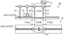
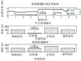
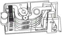
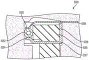
在诸如医疗应用特别是流体运送应用的各种应用中使用蠕动泵将受益于将来自系统的流体与其它流体隔离。一些蠕动泵通过压缩或挤压一定长度的挠性管件来工作。机械机构夹紧管件的一部分并且在旋转方向上推动被围困在管件中的任何流体。存在旋转蠕动泵和指形蠕动泵。Peristaltic pumps are used in various applications such as medical applications and especially fluid transport applications that would benefit from isolating fluid from the system from other fluids. Some peristaltic pumps work by compressing or squeezing a length of flexible tubing. A mechanical mechanism clamps a portion of the tubing and pushes any fluid trapped in the tubing in a rotational direction. There are rotary peristaltic pumps and finger peristaltic pumps.
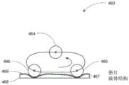
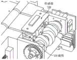
旋转蠕动泵通常使液体移动通过放置在弧形沟道中的挠性管。旋转蠕动泵一般由放置在由马达可旋转地驱动的辊载体上的两根至四根辊制成。典型旋转蠕动泵具有带有夹紧辊的转子组件,这些夹紧辊在隔开的位置处对挠性管施加压力以抵靠阻塞床在管件上提供挤压作用。管件的阻塞在挤压区域前面建立增加的压力并且在该区域后面产生减小的压力,从而随着转子组件使夹紧辊沿着管件移动压迫液体通过管件。为了操作,必须总是存在阻塞区;换言之,辊中的至少一个总是按压在管上。A rotary peristaltic pump typically moves liquid through a flexible tube placed in an arcuate channel. A rotary peristaltic pump is generally made of two to four rollers placed on a roller carrier that is rotatably driven by a motor. A typical rotary peristaltic pump has a rotor assembly with clamping rollers that apply pressure to the flexible tube at spaced locations to provide a squeezing action on the tubing against the blockage bed. The blockage of the tubing establishes increased pressure in front of the squeezing area and reduced pressure behind the area, thereby forcing liquid through the tubing as the rotor assembly moves the clamping rollers along the tubing. In order to operate, the blockage area must always be present; in other words, at least one of the rollers is always pressing on the tube.
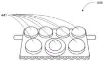
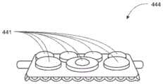
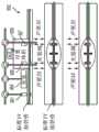
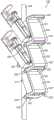
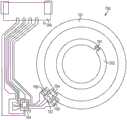
指形蠕动泵由一系列指形部制成,这一系列指形部以循环形式移动以抵靠计数器表面展平柔性管。指形部基本上以波状形式竖直地移动,形成从上游移动至下游的阻塞区。当第一指形部(最上游)压靠计数器表面时,最后指形部(最下游)升高。最常用的指形泵是线性的,意味着计数器表面是平坦的,并且指形部是平行的。在这种情况下,指形部受到一个布置在另一个后面的一系列凸轮的控制,各个凸轮与指形部合作。这些凸轮放置成在通过马达可旋转地驱动的公共轴上成螺旋形地偏移。还存在旋转指形蠕动泵,这些旋转指形蠕动泵尝试将辊泵的优点与指形泵的优点结合。在该类型的泵中,计数器表面不是平坦的而是弧形的,并且指形部径向地布置在计数器表面的内部。在这种情况下,具有放置在弧中部的多个旋钮的公共凸轮用来激活指形部。The finger-shaped peristaltic pump is made of a series of fingers that move in a cyclic form to flatten the flexible tube against the counter surface. The fingers move vertically in a basically wavy form, forming a blockage zone that moves from upstream to downstream. When the first finger (most upstream) is pressed against the counter surface, the last finger (most downstream) rises. The most commonly used finger pump is linear, meaning that the counter surface is flat and the fingers are parallel. In this case, the fingers are controlled by a series of cams arranged behind one another, and each cam cooperates with the fingers. These cams are placed to be offset spirally on a common shaft driven rotatably by a motor. There are also rotary finger peristaltic pumps that attempt to combine the advantages of roller pumps with the advantages of finger pumps. In this type of pump, the counter surface is not flat but arc-shaped, and the fingers are radially arranged inside the counter surface. In this case, a common cam with multiple knobs placed in the middle of the arc is used to activate the fingers.
发明内容Summary of the invention
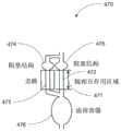
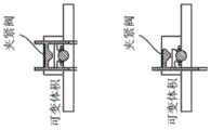
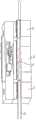
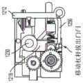
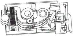
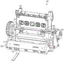
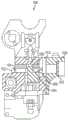
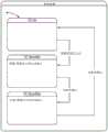
在本公开的一实施例中,一种用于泵送流体的泵,包括管压板、柱塞、偏置构件、入口阀和出口阀、致动器机构、位置传感器和处理器。柱塞被配置成当管压板被布置成与柱塞相对时朝向和远离管压板致动。管压板能够保持静脉输注管。偏置构件被配置成朝向管压板推动柱塞。可选地,柱塞可以是L形柱塞。In one embodiment of the present disclosure, a pump for pumping fluid includes a tube platen, a plunger, a biasing member, an inlet valve and an outlet valve, an actuator mechanism, a position sensor, and a processor. The plunger is configured to actuate toward and away from the tube platen when the tube platen is arranged opposite to the plunger. The tube platen is capable of holding an intravenous infusion tube. The biasing member is configured to push the plunger toward the tube platen. Optionally, the plunger can be an L-shaped plunger.
入口阀在柱塞的上游并且被配置成在阻塞位置与非阻塞位置之间致动。出口阀在柱塞的下游并且被配置成在阻塞位置与非阻塞位置之间致动。致动器机构控制柱塞、入口阀和出口阀的致动。位置传感器估计柱塞的位置。致动器机构可以是或包括凸轮轴。处理器耦接到位置传感器以从其接收估计的柱塞位置。当入口阀处于阻塞位置并且出口阀处于阻塞位置时,处理器部分地基于估计的柱塞位置检测异常。处理器可以被配置成基于柱塞的估计位置的变化率来检测泄漏。The inlet valve is upstream of the plunger and is configured to actuate between a blocked position and a non-blocked position. The outlet valve is downstream of the plunger and is configured to actuate between a blocked position and a non-blocked position. The actuator mechanism controls the actuation of the plunger, the inlet valve, and the outlet valve. The position sensor estimates the position of the plunger. The actuator mechanism may be or include a camshaft. The processor is coupled to the position sensor to receive an estimated plunger position therefrom. When the inlet valve is in a blocked position and the outlet valve is in a blocked position, the processor detects an anomaly based in part on the estimated plunger position. The processor may be configured to detect a leak based on a rate of change of the estimated position of the plunger.
泵可以进一步包括对输注管中的气体敏感的超声波传感器。超声波传感器可以位于柱塞的下游并且与处理器通信。处理器使用超声波传感器区别上游阻塞与流体中空气的存在。处理器可以基于当入口阀和出口阀两者都阻塞输注管时的柱塞位置以及基于由超声波传感器感测的感测气体来确定下游泵送的空气的体积。The pump may further include an ultrasonic sensor sensitive to gas in the infusion line. The ultrasonic sensor may be located downstream of the plunger and communicate with the processor. The processor uses the ultrasonic sensor to distinguish between an upstream blockage and the presence of air in the fluid. The processor may determine the volume of air pumped downstream based on the plunger position when both the inlet valve and the outlet valve block the infusion line and based on the sensed gas sensed by the ultrasonic sensor.
泵可以包括壳体和可枢转地耦接到该壳体的门。门枢转至打开位置并且枢转至关闭位置。管压板可以被布置在门上。管压板、门和柱塞被配置成使得柱塞被配置成当门处于关闭位置时朝向输注管和远离输注管致动。The pump may include a housing and a door pivotably coupled to the housing. The door pivots to an open position and pivots to a closed position. A tube platen may be disposed on the door. The tube platen, the door, and the plunger are configured such that the plunger is configured to actuate toward and away from the infusion tube when the door is in the closed position.
泵可以包括可枢转地耦接到门和具有至少第一位置和第二位置的杠杆。泵还可以包括耦接到门的闩。杠杆当处于第一位置时将门闩到壳体上。第一位置可以是杠杆朝向门枢转的位置。The pump may include a lever pivotably coupled to the door and having at least a first position and a second position. The pump may also include a latch coupled to the door. The lever latches the door to the housing when in the first position. The first position may be a position in which the lever is pivoted toward the door.
泵可以包括载体,该载体具有可枢转地耦接在一起的第一部分和第二部分。门和载体一起共同枢转。壳体包括第一槽和第二槽,当门处于打开位置时,载体的第一部分至少部分地布置在该第一槽中,当门处于打开位置时,载体的第二部分布置在该第二槽内。杠杆可操作地耦接到载体的第二部分,使得当门处于关闭位置时,朝向第一位置的杠杆致动将载体的第一部分和第二部分推动到壳体的第一槽中。The pump may include a carrier having a first portion and a second portion pivotally coupled together. The door and the carrier pivot together. The housing includes a first slot in which the first portion of the carrier is at least partially disposed when the door is in an open position and a second slot in which the second portion of the carrier is disposed when the door is in the open position. The lever is operably coupled to the second portion of the carrier such that when the door is in a closed position, actuation of the lever toward the first position pushes the first portion and the second portion of the carrier into the first slot of the housing.
致动器机构可以包括凸轮轴、入口阀凸轮、出口阀凸轮和柱塞。入口阀凸轮耦接到凸轮轴并且致动入口阀。出口阀凸轮耦接到凸轮轴并且致动出口阀。柱塞凸轮耦接到凸轮轴以致动柱塞。柱塞凸轮被配置成提升柱塞远离管压板。当仅偏置构件的力压迫柱塞朝向管压板时,处理器可以检测异常。处理器可以将数据(例如,异常)传达至监控客户端。也就是,数据可以包括异常的指示。The actuator mechanism may include a camshaft, an inlet valve cam, an outlet valve cam, and a plunger. The inlet valve cam is coupled to the camshaft and actuates the inlet valve. The outlet valve cam is coupled to the camshaft and actuates the outlet valve. The plunger cam is coupled to the camshaft to actuate the plunger. The plunger cam is configured to lift the plunger away from the tube pressure plate. When only the force of the biasing member presses the plunger toward the tube pressure plate, the processor can detect an anomaly. The processor can communicate data (e.g., an anomaly) to a monitoring client. That is, the data may include an indication of the anomaly.
在本公开的又一实施例中,泵包括管压板、柱塞、偏置构件、入口阀和出口阀、致动器机构、压力传感器和处理器。柱塞被配置成当管压板被布置成与柱塞相对时朝向和远离输注管致动。偏置构件朝向管压板推动柱塞。入口阀在柱塞的上游并且被配置成在阻塞位置与非阻塞位置之间致动。出口阀在柱塞的下游并且被配置成在阻塞位置与非阻塞位置之间致动。致动器机构被配置成控制柱塞、入口阀和出口阀的致动。压力传感器被为布置成与入口阀、出口阀、柱塞中的至少一个相邻。处理器耦接到压力传感器以从压力传感器接收压力信号。入口阀、出口阀和柱塞被配置成以多个循环泵送流体,各个循环具有波谷压力水平和波峰压力水平。处理器被配置成,当多个循环中的一个循环中波峰压力水平和波谷压力水平之间的差大于预定阈值时,使用压力信号确定下游阻塞存在。多个循环中的一个循环可以是单循环。压力信号可以在由处理器接收之前被滤波。泵可以包括模拟滤波器,该模拟滤波器被配置成在压力信号被处理器接收之前滤波压力信号。此外或备选地,处理器被配置成在确定下游阻塞是否存在之前数字地滤波压力信号。In another embodiment of the present disclosure, the pump includes a tube platen, a plunger, a biasing member, an inlet valve and an outlet valve, an actuator mechanism, a pressure sensor, and a processor. The plunger is configured to actuate toward and away from the infusion tube when the tube platen is arranged opposite to the plunger. The biasing member pushes the plunger toward the tube platen. The inlet valve is upstream of the plunger and is configured to actuate between a blocked position and a non-blocked position. The outlet valve is downstream of the plunger and is configured to actuate between a blocked position and a non-blocked position. The actuator mechanism is configured to control the actuation of the plunger, the inlet valve, and the outlet valve. The pressure sensor is arranged to be adjacent to at least one of the inlet valve, the outlet valve, and the plunger. The processor is coupled to the pressure sensor to receive a pressure signal from the pressure sensor. The inlet valve, the outlet valve, and the plunger are configured to pump fluid in multiple cycles, each cycle having a trough pressure level and a peak pressure level. The processor is configured to use the pressure signal to determine the presence of downstream obstruction when the difference between the peak pressure level and the trough pressure level in one of the multiple cycles is greater than a predetermined threshold. One of the plurality of cycles may be a single cycle. The pressure signal may be filtered before being received by the processor. The pump may include an analog filter configured to filter the pressure signal before the pressure signal is received by the processor. Additionally or alternatively, the processor is configured to digitally filter the pressure signal before determining whether a downstream obstruction exists.
在又一实施例中,用于泵送流体的泵包括管压板、柱塞、偏置构件、入口阀和出口阀、致动器机构、压力传感器和处理器。柱塞被配置成当管压板被布置成与柱塞相对时朝向和远离管致动。偏置构件朝向管压板推动柱塞。入口阀在柱塞的上游并且被配置成在阻塞位置与非阻塞位置之间致动。出口阀在柱塞的下游并且被配置成在阻塞位置与非阻塞位置之间致动。致动器机构控制柱塞、入口阀和出口阀的致动。压力传感器被为布置成与入口阀、出口阀、柱塞中的至少一个相邻。处理器耦接到压力传感器以从压力传感器接收压力信号。入口阀、出口阀和柱塞被配置成以多个循环泵送流体,各个循环具有波谷压力水平和波峰压力水平。处理器被配置成,当第一循环的第一波谷压力水平与第二循环的第二波谷压力水平之间的差大于预定阈值时,使用压力信号确定下游阻塞存在。In yet another embodiment, a pump for pumping fluid includes a tube platen, a plunger, a biasing member, an inlet valve and an outlet valve, an actuator mechanism, a pressure sensor, and a processor. The plunger is configured to actuate toward and away from the tube when the tube platen is arranged opposite to the plunger. The biasing member pushes the plunger toward the tube platen. The inlet valve is upstream of the plunger and is configured to actuate between a blocked position and a non-blocked position. The outlet valve is downstream of the plunger and is configured to actuate between a blocked position and a non-blocked position. The actuator mechanism controls the actuation of the plunger, the inlet valve, and the outlet valve. The pressure sensor is arranged to be adjacent to at least one of the inlet valve, the outlet valve, and the plunger. The processor is coupled to the pressure sensor to receive a pressure signal from the pressure sensor. The inlet valve, the outlet valve, and the plunger are configured to pump fluid in multiple cycles, each cycle having a trough pressure level and a peak pressure level. The processor is configured to use the pressure signal to determine the presence of downstream obstruction when the difference between the first trough pressure level of the first cycle and the second trough pressure level of the second cycle is greater than a predetermined threshold.
处理器可以是微处理器、微控制器、PLD、PLA、CPLD和/或FPGA中的一个或多个。第一循环和第二循环是所述多个循环中的循环。第一循环和第二循环可以是连续的循环。The processor may be one or more of a microprocessor, a microcontroller, a PLD, a PLA, a CPLD and/or an FPGA. The first loop and the second loop are loops in the plurality of loops. The first loop and the second loop may be continuous loops.
压力信号可以在由处理器接收之前被滤波。泵可以包括模拟滤波器,该模拟滤波器被配置成在压力信号由处理器接收之前滤波压力信号。在确定下游阻塞是否存在之前,处理器可以数字地滤波压力信号。The pressure signal may be filtered prior to being received by the processor. The pump may include an analog filter configured to filter the pressure signal prior to being received by the processor. Prior to determining whether a downstream obstruction exists, the processor may digitally filter the pressure signal.
在又一实施例中,用于泵送流体的泵包括管压板、柱塞、偏置构件、入口阀和出口阀、致动器机构、压力传感器和处理器。柱塞被配置成当管压板被布置成与柱塞相对时朝向和远离管致动。偏置构件推动朝管压板柱塞。入口阀在柱塞的上游并且被配置成在阻塞位置与非阻塞位置之间致动。出口阀在柱塞的下游并且被配置成在阻塞位置与非阻塞位置之间致动。致动器机构控制柱塞、入口阀和出口阀的致动。压力传感器被为布置成与入口阀、出口阀、柱塞中的至少一个相邻。处理器耦接到压力传感器以从压力传感器接收压力信号。入口阀、出口阀和柱塞被配置成以多个循环泵送流体,各个循环具有波谷压力水平和波峰压力水平。处理器被配置成,当所述多个循环的各个连续波谷到波谷压力值之和大于预定阈值时,确定下游阻塞存在。In yet another embodiment, a pump for pumping fluid includes a tube platen, a plunger, a biasing member, an inlet valve and an outlet valve, an actuator mechanism, a pressure sensor, and a processor. The plunger is configured to actuate toward and away from the tube when the tube platen is arranged opposite to the plunger. The biasing member pushes the plunger toward the tube platen. The inlet valve is upstream of the plunger and is configured to actuate between a blocked position and a non-blocked position. The outlet valve is downstream of the plunger and is configured to actuate between a blocked position and a non-blocked position. The actuator mechanism controls the actuation of the plunger, the inlet valve, and the outlet valve. The pressure sensor is arranged to be adjacent to at least one of the inlet valve, the outlet valve, and the plunger. The processor is coupled to the pressure sensor to receive a pressure signal from the pressure sensor. The inlet valve, the outlet valve, and the plunger are configured to pump fluid in multiple cycles, each cycle having a trough pressure level and a peak pressure level. The processor is configured to determine that downstream obstruction exists when the sum of each continuous trough to trough pressure value of the multiple cycles is greater than a predetermined threshold.
压力信号可以在由处理器接收之前被滤波。泵可以包括模拟滤波器和/或数字滤波器,该模拟滤波器被配置成在压力信号由处理器接收之前滤波压力信号,该数字滤波器在前确定下游阻塞是否存在之前滤波压力信号。The pressure signal may be filtered prior to being received by the processor. The pump may include an analog filter configured to filter the pressure signal prior to being received by the processor and/or a digital filter that filters the pressure signal prior to determining whether a downstream obstruction exists.
处理器可以将调整值添加到和,使得和表示多个循环的当前循环的波谷水平相对于所有多个循环的最低波谷值之间的差。The processor may add the adjustment value to φ and φ such that φ and φ represent a difference between the trough level of a current cycle of the plurality of cycles relative to a lowest trough value of all the plurality of cycles.
在又一实施例中,用于泵送流体的泵包括管压板、柱塞、偏置构件、入口阀和出口阀、致动器机构、压力传感器和处理器。柱塞被配置成当管压板被布置成与柱塞相对时朝向和远离管致动。偏置构件推动朝管压板柱塞。入口阀在柱塞的上游并且被配置成在阻塞位置与非阻塞位置之间致动。出口阀在柱塞的下游并且被配置成在阻塞位置与非阻塞位置之间致动。致动器机构控制柱塞、入口阀和出口阀的致动。压力传感器被为布置成与入口阀、出口阀、柱塞中的至少一个相邻。处理器耦接到压力传感器以从压力传感器接收压力信号。入口阀、出口阀和柱塞被配置成以多个循环泵送流体,各个循环具有波谷压力水平和波峰压力水平。处理器被配置成,使用压力信号,当多个循环中的一个循环的波谷比所有多个循环的最低波谷大预定量时,确定下游阻塞存在。In yet another embodiment, a pump for pumping fluid includes a tube platen, a plunger, a biasing member, an inlet valve and an outlet valve, an actuator mechanism, a pressure sensor, and a processor. The plunger is configured to actuate toward and away from the tube when the tube platen is arranged opposite to the plunger. The biasing member pushes the plunger toward the tube platen. The inlet valve is upstream of the plunger and is configured to actuate between a blocked position and a non-blocked position. The outlet valve is downstream of the plunger and is configured to actuate between a blocked position and a non-blocked position. The actuator mechanism controls the actuation of the plunger, the inlet valve, and the outlet valve. The pressure sensor is arranged to be adjacent to at least one of the inlet valve, the outlet valve, and the plunger. The processor is coupled to the pressure sensor to receive a pressure signal from the pressure sensor. The inlet valve, the outlet valve, and the plunger are configured to pump fluid in multiple cycles, each cycle having a trough pressure level and a peak pressure level. The processor is configured to use the pressure signal to determine that a downstream blockage exists when the trough of one of the multiple cycles is greater than the lowest trough of all the multiple cycles by a predetermined amount.
压力信号可以在由处理器接收之前被滤波。泵可以包括模拟滤波器,该模拟滤波器被配置成在压力信号由处理器接收之前滤波压力信号。在确定下游阻塞是否存在之前,处理器可以数字地滤波压力信号。The pressure signal may be filtered prior to being received by the processor. The pump may include an analog filter configured to filter the pressure signal prior to being received by the processor. Prior to determining whether a downstream obstruction exists, the processor may digitally filter the pressure signal.
在又一实施例中,用于泵送流体的泵包括管压板、柱塞、偏置构件、入口阀和出口阀、致动器机构、压力传感器和处理器。柱塞被配置成当管压板被布置成与柱塞相对时朝向和远离管致动。偏置构件推动朝管压板柱塞。入口阀在柱塞的上游并且被配置成在阻塞位置与非阻塞位置之间致动。出口阀在柱塞的下游并且被配置成在阻塞位置与非阻塞位置之间致动。致动器机构控制柱塞、入口阀和出口阀的致动。压力传感器被为布置成与入口阀、出口阀、柱塞中的至少一个相邻。处理器耦接到压力传感器以从压力传感器接收压力信号。入口阀、出口阀和柱塞被配置成以多个循环泵送流体,各个循环具有波谷压力水平和波峰压力水平。处理器被配置成使用压力信号,当差大于预定阈值时,确定下游阻塞存在,其中,该差为从(2)波谷到波谷值减去(1)多个循环的连续的一系列的连续波谷到波谷压力值的滤波值。In yet another embodiment, a pump for pumping a fluid comprises a tube platen, a plunger, a biasing member, an inlet valve and an outlet valve, an actuator mechanism, a pressure sensor, and a processor. The plunger is configured to actuate toward and away from the tube when the tube platen is arranged opposite to the plunger. The biasing member pushes the plunger toward the tube platen. The inlet valve is upstream of the plunger and is configured to actuate between a blocked position and a non-blocked position. The outlet valve is downstream of the plunger and is configured to actuate between a blocked position and a non-blocked position. The actuator mechanism controls the actuation of the plunger, the inlet valve, and the outlet valve. The pressure sensor is arranged to be adjacent to at least one of the inlet valve, the outlet valve, and the plunger. The processor is coupled to the pressure sensor to receive a pressure signal from the pressure sensor. The inlet valve, the outlet valve, and the plunger are configured to pump the fluid in multiple cycles, each cycle having a trough pressure level and a peak pressure level. The processor is configured to use the pressure signal to determine that a downstream obstruction exists when a difference is greater than a predetermined threshold, wherein the difference is a filtered value of (1) a continuous series of consecutive trough to trough pressure values over a plurality of cycles minus (2) a trough to trough value.
压力信号可以在由处理器接收之前被滤波。泵可以包括模拟滤波器,该模拟滤波器被配置成在压力信号由处理器接收之前滤波压力信号。在确定下游阻塞是否存在之前,处理器可以数字地滤波压力信号。The pressure signal may be filtered prior to being received by the processor. The pump may include an analog filter configured to filter the pressure signal prior to being received by the processor. Prior to determining whether a downstream obstruction exists, the processor may digitally filter the pressure signal.
在又一实施例中,用于泵送流体的泵包括管压板、柱塞、偏置构件、入口阀和出口阀、致动器机构、压力传感器和处理器。柱塞被配置成当管压板被布置成与柱塞相对时朝向和远离管致动。偏置构件推动朝管压板柱塞。入口阀在柱塞的上游并且被配置成在阻塞位置与非阻塞位置之间致动。出口阀在柱塞的下游并且被配置成在阻塞位置与非阻塞位置之间致动。致动器机构控制柱塞、入口阀和出口阀的致动。压力传感器被为布置成与入口阀、出口阀、柱塞中的至少一个相邻。处理器耦接到压力传感器以从压力传感器接收压力信号。入口阀、出口阀和柱塞被配置成以多个循环泵送流体,每个循环具有波谷压力水平和波峰压力水平。处理器被配置成使用压力信号:(1)如果多个循环中的任意循环中波峰压力水平与波谷压力水平之间的差大于第一预定阈值,则确定下游阻塞存在,(2)如果第一循环的第一波谷压力水平与第二循环的第二波谷压力水平之间的差大于第二预定阈值,则确定压力下游阻塞存在,第一循环和第二循环是多个循环中的循环,(3)如果所述多个循环中的循环的波谷比所有多个循环的最低波谷大第三预定阈值,则确定下游阻塞存在,和(4)如果从波谷到波谷值减去所述多个循环的连续的一系列的连续波谷到波谷压力值的滤波值大于第四预定阈值,则处理器确定下游阻塞存在。In yet another embodiment, a pump for pumping a fluid includes a tube platen, a plunger, a biasing member, an inlet valve and an outlet valve, an actuator mechanism, a pressure sensor, and a processor. The plunger is configured to actuate toward and away from the tube when the tube platen is arranged opposite to the plunger. The biasing member pushes the plunger toward the tube platen. The inlet valve is upstream of the plunger and is configured to actuate between a blocked position and a non-blocked position. The outlet valve is downstream of the plunger and is configured to actuate between a blocked position and a non-blocked position. The actuator mechanism controls the actuation of the plunger, the inlet valve, and the outlet valve. The pressure sensor is arranged to be adjacent to at least one of the inlet valve, the outlet valve, and the plunger. The processor is coupled to the pressure sensor to receive a pressure signal from the pressure sensor. The inlet valve, the outlet valve, and the plunger are configured to pump the fluid in multiple cycles, each cycle having a trough pressure level and a peak pressure level. The processor is configured to use the pressure signal to: (1) determine that a downstream obstruction exists if the difference between a peak pressure level and a trough pressure level in any cycle of a plurality of cycles is greater than a first predetermined threshold, (2) determine that a pressure downstream obstruction exists if the difference between a first trough pressure level of a first cycle and a second trough pressure level of a second cycle is greater than a second predetermined threshold, the first cycle and the second cycle being cycles of a plurality of cycles, (3) determine that a downstream obstruction exists if a trough of a cycle of the plurality of cycles is greater than a third predetermined threshold than a lowest trough of all the plurality of cycles, and (4) determine that a downstream obstruction exists if a filtered value obtained by subtracting a continuous series of consecutive trough-to-trough pressure values of the plurality of cycles from the trough-to-trough value is greater than a fourth predetermined threshold.
处理器可以执行所有估计(1)-(4)来确定下游阻塞是否存在。处理器被配置成将数据传达至监控客户端。压力信号可以在由处理器接收之前被滤波。泵可以包括模拟滤波器,该模拟滤波器被配置成在压力信号由处理器接收之前滤波压力信号。在确定下游阻塞是否存在之前,处理器可以数字地滤波压力信号。The processor may perform all of the evaluations (1)-(4) to determine whether a downstream obstruction exists. The processor is configured to communicate the data to a monitoring client. The pressure signal may be filtered prior to being received by the processor. The pump may include an analog filter configured to filter the pressure signal prior to being received by the processor. The processor may digitally filter the pressure signal prior to determining whether a downstream obstruction exists.
致动器机构可以进一步包括:耦接到凸轮轴的入口阀凸轮,其被配置成致动入口阀;耦接到凸轮轴的出口阀凸轮,其被配置成致动出口阀;和耦接到凸轮轴的柱塞凸轮,其被配置成致动柱塞。柱塞凸轮可以被配置成提升柱塞远离管压板。柱塞凸轮可以被配置成使得柱塞凸轮能够仅压缩偏置构件并且不压迫柱塞朝向管压板。The actuator mechanism may further include: an inlet valve cam coupled to the camshaft, configured to actuate the inlet valve; an outlet valve cam coupled to the camshaft, configured to actuate the outlet valve; and a plunger cam coupled to the camshaft, configured to actuate the plunger. The plunger cam may be configured to lift the plunger away from the tube platen. The plunger cam may be configured so that the plunger cam can only compress the biasing member and not press the plunger toward the tube platen.
柱塞凸轮可以被配置成仅抵靠偏置构件致动柱塞远离管压板,并且柱塞凸轮和偏置构件被配置成使得仅偏置构件的力能够压缩布置在管压板内的管。The plunger cam may be configured to actuate the plunger away from the tube platen only against a biasing member, and the plunger cam and biasing member are configured such that only the force of the biasing member is able to compress the tube disposed within the tube platen.
在本公开的另一实施例中,泵包括管压板和柱塞。柱塞被配置成朝向管压板致动。柱塞的端部具有倒圆端,并且管压板的底部具有大体U形,该大体U形在柱塞与管压板之间提供约等于输注管的壁厚的二倍至三倍的径向间隙。沿着柱塞的运动路径柱塞与管压板之间的最小距离可以受到管压板上的接触柱塞的一部分的表面的限制。In another embodiment of the present disclosure, a pump includes a tube platen and a plunger. The plunger is configured to actuate toward the tube platen. The end of the plunger has a rounded end, and the bottom of the tube platen has a generally U-shape that provides a radial gap between the plunger and the tube platen that is approximately equal to two to three times the wall thickness of the infusion tube. The minimum distance between the plunger and the tube platen along the path of movement of the plunger can be limited by the surface of a portion of the tube platen that contacts the plunger.
在另一实施例中,泵包括管压板和柱塞。管压板限定井和第一接触部。柱塞被配置成朝向管压板致动。柱塞具有倒圆末端和第二接触部。管压板和柱塞被配置成使得,当第一接触部和第二接触部彼此接触时,柱塞朝向管压板的致动被阻碍。第一接触部和第二接触部可以被配置成彼此接触以在管压板的井与柱塞的倒圆末端之间留下预定间隙。In another embodiment, a pump includes a tube platen and a plunger. The tube platen defines a well and a first contact portion. The plunger is configured to actuate toward the tube platen. The plunger has a rounded tip and a second contact portion. The tube platen and the plunger are configured such that, when the first contact portion and the second contact portion contact each other, actuation of the plunger toward the tube platen is impeded. The first contact portion and the second contact portion can be configured to contact each other to leave a predetermined gap between the well of the tube platen and the rounded tip of the plunger.
预定间隙可以被配置成防止布置在管压板内的输注管完全关闭。预定间隙可以被配置成促使布置在管压板内的输注管部分地阻塞输注管内的流体流。The predetermined gap may be configured to prevent the infusion tube disposed in the tube platen from completely closing. The predetermined gap may be configured to cause the infusion tube disposed in the tube platen to partially block the fluid flow in the infusion tube.
在另一实施例中,泵包括管压板和柱塞。管压板限定井和第一接触部。柱塞被配置成朝向管压板致动,并且柱塞具有倒圆末端和第二接触部。管压板和柱塞被配置成使得,当第一接触部和第二接触部彼此接触时,柱塞朝向管压板的致动被阻碍。第一接触部和第二接触部彼此接触,使得倒圆末端与管压板之间的间隙为约等于比布置在管压板内的输注管的壁厚的两倍大出约百分之八。倒圆末端可以具有小于布置在管压板的井内的管的未压缩管直径的宽度。管压板可以被配置成接收预定范围的输注管大小,和/或管压板可以被配置成接收预定输注管大小。In another embodiment, a pump includes a tube platen and a plunger. The tube platen defines a well and a first contact portion. The plunger is configured to actuate toward the tube platen, and the plunger has a rounded tip and a second contact portion. The tube platen and the plunger are configured such that, when the first contact portion and the second contact portion contact each other, actuation of the plunger toward the tube platen is impeded. The first contact portion and the second contact portion contact each other such that a gap between the rounded tip and the tube platen is approximately equal to about eight percent greater than twice the wall thickness of an infusion tube disposed within the tube platen. The rounded tip may have a width that is less than an uncompressed tube diameter of a tube disposed within the well of the tube platen. The tube platen may be configured to receive a predetermined range of infusion tube sizes, and/or the tube platen may be configured to receive a predetermined infusion tube size.
在本公开的又一实施例中,泵包括限定井的管压板和被配置成朝向管压板致动的柱塞。柱塞具有倒圆末端。倒圆末端具有小于布置在管压板的井内的管的未压缩管直径的宽度。管压板可以被配置成接收预定输注管大小。在另一实施例中,倒圆末端具有小于布置在管压板的井内的管的未压缩管半径的半径。In yet another embodiment of the present disclosure, a pump includes a tube platen defining a well and a plunger configured to actuate toward the tube platen. The plunger has a rounded tip. The rounded tip has a width that is less than an uncompressed tube diameter of a tube disposed within the well of the tube platen. The tube platen can be configured to receive a predetermined infusion tube size. In another embodiment, the rounded tip has a radius that is less than an uncompressed tube radius of a tube disposed within the well of the tube platen.
在另一实施例中,泵包括限定井和第一接触部的管压板和被配置成朝向管压板致动的柱塞。柱塞具有倒圆末端和第二接触部。管压板和柱塞被配置成使得,当第一接触部和第二接触部彼此接触时,柱塞朝向管压板的致动被阻碍。第一接触部和第二接触部彼此接触,使得倒圆末端与管压板之间的间隙为约等于略大于布置在井内管的壁厚的两倍。管压板可以被配置成接收预定输注管大小。In another embodiment, a pump includes a tube platen defining a well and a first contact portion and a plunger configured to actuate toward the tube platen. The plunger has a rounded tip and a second contact portion. The tube platen and the plunger are configured such that, when the first contact portion and the second contact portion contact each other, actuation of the plunger toward the tube platen is impeded. The first contact portion and the second contact portion contact each other such that a gap between the rounded tip and the tube platen is approximately equal to slightly greater than twice the wall thickness of a tube disposed in the well. The tube platen can be configured to receive a predetermined infusion tube size.
在本公开的另一个实施例中,泵包括壳体、门、载体和杠杆手柄。壳体具有第一槽。门可枢转地耦接到壳体并且具有被配置成接收管的压板。门被配置成具有关闭位置和打开位置。门包括第二槽。载体具有枢轴,该枢轴限定可枢转地耦接在一起的第一部分和第二部分。当门打开时,第一部分可滑动地布置在壳体的第一槽内,并且第二部分可滑动地布置在门的第二槽内。杠杆手柄可枢转地耦接到门并且可操作地耦接到载体。In another embodiment of the present disclosure, a pump includes a housing, a door, a carrier, and a lever handle. The housing has a first slot. The door is pivotally coupled to the housing and has a pressure plate configured to receive a tube. The door is configured to have a closed position and an open position. The door includes a second slot. The carrier has a pivot that defines a first portion and a second portion that are pivotally coupled together. When the door is open, the first portion is slidably disposed in the first slot of the housing and the second portion is slidably disposed in the second slot of the door. The lever handle is pivotally coupled to the door and operably coupled to the carrier.
泵可以进一步包括被配置成阻塞管的阀。载体可以被配置成固持滑动阻塞器。当门处于关闭位置并且杠杆手柄处于完全打开位置时,载体被配置成将滑动阻塞器固持在第一部分和第二部分内使得滑动阻塞器完全阻塞管。在将载体致动到门的第一槽中使得管不被滑动阻塞器阻塞之前,杠杆手柄朝向壳体的初始致动使所述阀致动以阻塞管。The pump may further include a valve configured to block the tube. The carrier may be configured to retain a sliding occluder. When the door is in a closed position and the lever handle is in a fully open position, the carrier is configured to retain the sliding occluder within the first portion and the second portion such that the sliding occluder fully blocks the tube. Before actuating the carrier into the first slot of the door such that the tube is not blocked by the sliding occluder, initial actuation of the lever handle toward the housing actuates the valve to block the tube.
杠杆手柄可操作地耦接到载体的第二部分,使得杠杆手柄远离壳体的致动使载体的第一部分和第二部分远离第一槽移动,由此使布置在载体内的滑动阻塞器移动至阻塞位置,使得杠杆手柄远离壳体的至少一些致动在不使滑动阻塞器移动的情况下发生。The lever handle is operably coupled to the second portion of the carrier such that actuation of the lever handle away from the housing moves the first and second portions of the carrier away from the first slot, thereby moving a sliding occluder disposed within the carrier to an occluding position, such that at least some actuation of the lever handle away from the housing occurs without moving the sliding occluder.
门可以经铰链可枢转地耦接到壳体,当门处于关闭位置时,门可以触摸壳体的面,并且铰链可以被配置成允许门相对于壳体从当门处于打开位置时相对于壳体面的垂直位置移动至当门处于关闭位置时与壳体面相邻。The door can be pivotally coupled to the shell via a hinge so that the door can touch a face of the shell when the door is in a closed position, and the hinge can be configured to allow the door to move relative to the shell from a vertical position relative to the shell face when the door is in an open position to adjacent to the shell face when the door is in a closed position.
载体的第二部分可以设有键以在仅预定定向上接收滑动阻塞器。门为载体的第二部分限定键,使得载体的第二部分在仅预定定向上接收滑动阻塞器。The second portion of the carrier may be keyed to receive the slide occluder in only a predetermined orientation. The door defines a key for the second portion of the carrier such that the second portion of the carrier receives the slide occluder in only a predetermined orientation.
泵可以包括滑动阻塞器传感器,该滑动阻塞器传感器被配置成,当将滑动阻塞器为适当地插入到载体中,门关闭,并且杠杆手柄完全朝向门致动时,检测滑动阻塞器的存在。The pump may include a slide occluder sensor configured to detect the presence of the slide occluder when the slide occluder is properly inserted into the carrier, the door is closed, and the lever handle is fully actuated toward the door.
在一些实施例中,泵可以进一步包括被配置成阻塞管的阀。载体被配置成固持滑动阻塞器。当门处于关闭位置并且杠杆手柄处于完全打开位置时,载体被配置成将滑动阻塞器固持在第一部分和第二部分内使得滑动阻塞器完全阻塞管。当杠杆手柄处于完全关闭位置时,杠杆手柄远离壳体的初始致动在将阀致动到非阻塞位置之前将载体致动到阻塞位置。In some embodiments, the pump may further include a valve configured to block the tube. The carrier is configured to retain a sliding occluder. When the door is in the closed position and the lever handle is in the fully open position, the carrier is configured to retain the sliding occluder within the first portion and the second portion such that the sliding occluder fully blocks the tube. When the lever handle is in the fully closed position, initial actuation of the lever handle away from the housing actuates the carrier to the blocking position before actuating the valve to the non-blocking position.
在一些实施例中,泵进一步包括被配置成阻塞管的阀。载体被配置成固持滑动阻塞器。当门处于关闭位置并且杠杆手柄处于完全关闭位置时,载体被配置成将滑动阻塞器固持在第一部分和第二部分内,使得滑动阻塞器完全阻塞管。杠杆手柄远离壳体的初始致动在将阀致动到非阻塞位置之前将载体致动到阻塞位置。在杠杆手柄远离门的充分致动之后,门可以变成与壳体解闩。In some embodiments, the pump further includes a valve configured to block the tube. The carrier is configured to retain the sliding occluder. When the door is in the closed position and the lever handle is in the fully closed position, the carrier is configured to retain the sliding occluder within the first portion and the second portion so that the sliding occluder fully blocks the tube. Initial actuation of the lever handle away from the housing actuates the carrier to the blocking position before actuating the valve to the non-blocking position. After sufficient actuation of the lever handle away from the door, the door can become unlatched from the housing.
在本公开的又一个实施例中,泵包括壳体、门和载体。壳体具有第一槽。门可枢转地耦接到壳体并且具有被配置成接收管的压板。门被配置成具有关闭位置和打开位置,并且包括第二槽。载体具有枢轴,该枢轴限定可枢转地耦接在一起的第一部分和第二部分,其中,当门打开时,第一部分可滑动地布置在壳体的第一槽内,并且第二部分可滑动地布置在门的第二槽内。In yet another embodiment of the present disclosure, a pump includes a housing, a door, and a carrier. The housing has a first slot. The door is pivotally coupled to the housing and has a pressure plate configured to receive a tube. The door is configured to have a closed position and an open position and includes a second slot. The carrier has a pivot defining a first portion and a second portion pivotally coupled together, wherein, when the door is open, the first portion is slidably disposed in the first slot of the housing and the second portion is slidably disposed in the second slot of the door.
在本公开的另一个实施例中,泵包括泵送机构、马达、旋转传感器、计数器以及第一处理器和第二处理器。泵送机构被配置成泵送流体。马达耦接到泵送机构以致动泵送机构。旋转传感器耦接到马达并且被配置成产生多个脉冲,其中,所述多个脉冲中的各个脉冲指示马达的旋转(例如,全程旋转或诸如2度的局部旋转)。计数器为耦接到旋转传感器以对多个脉冲中的各个脉冲计数。第一处理器可操作地耦接到旋转传感器以监控多个脉冲。第二处理器可操作地耦接到计数器以监控多个脉冲中的计数脉冲。第一处理器和第二处理器彼此可操作通信。第一处理器和第二处理器被配置成确定由第一处理器确定的监控的多个脉冲是否对应于如由第二处理器从计数器接收的计数脉冲。In another embodiment of the present disclosure, the pump includes a pumping mechanism, a motor, a rotation sensor, a counter, and a first processor and a second processor. The pumping mechanism is configured to pump fluid. The motor is coupled to the pumping mechanism to actuate the pumping mechanism. The rotation sensor is coupled to the motor and is configured to generate a plurality of pulses, wherein each of the plurality of pulses indicates the rotation of the motor (e.g., a full rotation or a partial rotation such as 2 degrees). The counter is coupled to the rotation sensor to count each of the plurality of pulses. The first processor is operably coupled to the rotation sensor to monitor the plurality of pulses. The second processor is operably coupled to the counter to monitor the count pulses in the plurality of pulses. The first processor and the second processor are operably in communication with each other. The first processor and the second processor are configured to determine whether the plurality of pulses monitored determined by the first processor correspond to the count pulses received from the counter as by the second processor.
当由第一处理器确定的监控的多个脉冲与如由第二处理器从计数器接收的计数脉冲一致达预定量时,由第一处理器确定的监控的多个脉冲对应如由第二处理器从计数器接收的计数脉冲。预定量可以是百分比量、多个脉冲中的预定数量的脉冲和/或预定角度值。多个脉冲中的各个脉冲可以对应于马达的预定数量的旋转度。The monitored plurality of pulses determined by the first processor corresponds to the count pulses as received from the counter by the second processor when the monitored plurality of pulses determined by the first processor agrees with the count pulses as received from the counter by the second processor by a predetermined amount. The predetermined amount may be a percentage amount, a predetermined number of pulses in the plurality of pulses, and/or a predetermined angular value. Each pulse in the plurality of pulses may correspond to a predetermined number of degrees of rotation of the motor.
第一处理器可以将监控的多个脉冲听计数数量传达至第二处理器。第一处理器可以使用监控的多个脉冲来确定传递的第一估计体积量。第二处理器可以使用多个脉冲中的计数脉冲来确定所传递的第二估计体积量。当所传递的第一估计体积量和第二估计体积量没有一致达预定量时,第一处理器和第二处理器中的一个或两个发出警告。The first processor may communicate the monitored plurality of pulses to the second processor. The first processor may use the monitored plurality of pulses to determine the first estimated volume delivered. The second processor may use the counted pulses in the plurality of pulses to determine the second estimated volume delivered. When the first estimated volume delivered and the second estimated volume delivered do not agree by a predetermined amount, one or both of the first processor and the second processor may issue a warning.
在另一个实施例中,泵包括泵送机构、马达、旋转传感器、计数器以及第一处理器和第二处理器。泵送机构被配置成泵送流体。马达耦接到泵送机构以致动泵送机构。旋转传感器耦接到马达并且被配置成产生多个脉冲。多个脉冲中的各个脉冲可以指示马达的旋转。耦接到旋转传感器的计数器计算多个脉冲中的各个脉冲。第一处理器可操作地耦接到旋转传感器以监控多个脉冲以估计所泵送的流体的第一体积。第二处理器可操作地耦接到计数器以监控多个脉冲的计数脉冲以估计所泵送的流体的第二体积。第一处理器和第二处理器彼此可操作通信。第一处理器和第二处理器被配置成确定所估计的泵送流体的第一体积相对于所估计的泵送流体的第二体积是否在预定范围内。第一处理器可以控制马达的操作。第二处理器可以控制马达的操作。第二处理器可以被耦接到用户界面以从其接收用户输入。In another embodiment, the pump includes a pumping mechanism, a motor, a rotation sensor, a counter, and a first processor and a second processor. The pumping mechanism is configured to pump a fluid. The motor is coupled to the pumping mechanism to actuate the pumping mechanism. The rotation sensor is coupled to the motor and is configured to generate a plurality of pulses. Each pulse in the plurality of pulses may indicate the rotation of the motor. The counter coupled to the rotation sensor counts each pulse in the plurality of pulses. The first processor is operably coupled to the rotation sensor to monitor the plurality of pulses to estimate a first volume of the pumped fluid. The second processor is operably coupled to the counter to monitor the count pulses of the plurality of pulses to estimate a second volume of the pumped fluid. The first processor and the second processor are operably communicated with each other. The first processor and the second processor are configured to determine whether the estimated first volume of the pumped fluid is within a predetermined range relative to the estimated second volume of the pumped fluid. The first processor may control the operation of the motor. The second processor may control the operation of the motor. The second processor may be coupled to a user interface to receive user input therefrom.
预定范围可以是相对于所估计的泵送流体的第一体积和第二体积中的一个的百分比量、相对于所估计的泵送流体的第一体积和/或相对于所估计的泵送流体的第二体积的范围。The predetermined range may be a percentage amount relative to one of the estimated first and second volumes of the pumped fluid, a range relative to the estimated first volume of the pumped fluid, and/or relative to the estimated second volume of the pumped fluid.
当所估计的泵送流体的第一体积和第二体积不符合在预定范围内时,第一处理器和第二处理器中的一个或两个发出警告。第一处理器可以将所估计的泵送流体的第一体积传达至第二处理器,使得第二处理器确定所估计的泵送流体的第一体积相对于所估计的泵送流体的第二体积是否在预定范围内。第二处理器可以将所估计的泵送流体的第二体积传达至第一处理器,使得第一处理器确定所估计的泵送流体的第一体积相对于所估计的泵送流体的第二体积是否在预定范围内。When the estimated first volume and second volume of the pumped fluid do not meet within the predetermined range, one or both of the first processor and the second processor issues a warning. The first processor can communicate the estimated first volume of the pumped fluid to the second processor so that the second processor determines whether the estimated first volume of the pumped fluid is within the predetermined range relative to the estimated second volume of the pumped fluid. The second processor can communicate the estimated second volume of the pumped fluid to the first processor so that the first processor determines whether the estimated first volume of the pumped fluid is within the predetermined range relative to the estimated second volume of the pumped fluid.
在本公开的另一个实施例中,用于泵送流体的泵包括壳体、门、管压板、柱塞、阀、一个或多个钩闩和杠杆。壳体具有一个或多个销。门可枢转地耦接到壳体。管压板布置在门上。柱塞被配置成当管压板被布置成与柱塞相对时朝向和远离输注管致动。阀被布置在柱塞的上游或下游并且被配置成在阻塞位置与非阻塞位置之间致动。杠杆手柄可操作地耦接到一个或多个钩闩以致动一个或多个钩闩以闩到壳体的一个或多个销上。In another embodiment of the present disclosure, a pump for pumping fluid includes a housing, a door, a tube pressure plate, a plunger, a valve, one or more hook latches and a lever. The housing has one or more pins. The door is pivotally coupled to the housing. The tube pressure plate is arranged on the door. The plunger is configured to actuate toward and away from the infusion tube when the tube pressure plate is arranged opposite to the plunger. The valve is arranged upstream or downstream of the plunger and is configured to actuate between a blocking position and a non-blocking position. The lever handle is operably coupled to the one or more hook latches to actuate the one or more hook latches to latch to one or more pins of the housing.
泵可以包括弹簧,该弹簧被配置成,当将一个或多个钩闩闩到一个或多个销上时,该弹簧朝向壳体推动门。弹簧可以是片簧,并且可以在至少一个钩闩与门之间提供机械接合。杠杆手柄将一个或多个钩闩闩到一个或多个销的致动还可以致动阀以阻塞管。杠杆手柄将一个或多个钩闩与一个或多个销解闩的致动也将阀致动到非阻塞位置。偏置构件可以被配置成朝向管压板推动柱塞。The pump may include a spring configured to push the door toward the housing when the one or more hook latches are latched to the one or more pins. The spring may be a leaf spring and may provide a mechanical engagement between at least one hook latch and the door. Actuation of the lever handle to latch the one or more hook latches to the one or more pins may also actuate the valve to block the tube. Actuation of the lever handle to unlatch the one or more hook latches from the one or more pins also actuates the valve to a non-blocking position. The biasing member may be configured to push the plunger toward the tube platen.
在本公开的另一个实施例中,泵包括壳体和门。壳体具有前侧以及第一侧和第二侧。门可枢转地耦接到第一侧并且限定切口部分。泵可以包括可枢转地耦接到门的杠杆手柄。泵可以具有减震器,当门处于关闭位置时,该减震器耦接到壳体的第一侧并且布置在门的切口部分内。杠杆手柄包括杠杆切口部分,该杠杆切口部分定位成使得,当门处于关闭位置并且杠杆手柄处于关闭位置时,减震器被布置在杠杆切口部分内。In another embodiment of the present disclosure, a pump includes a housing and a door. The housing has a front side and a first side and a second side. The door is pivotally coupled to the first side and defines a cutout portion. The pump may include a lever handle pivotally coupled to the door. The pump may have a shock absorber that is coupled to the first side of the housing and disposed within the cutout portion of the door when the door is in a closed position. The lever handle includes a lever cutout portion that is positioned so that the shock absorber is disposed within the lever cutout portion when the door is in the closed position and the lever handle is in the closed position.
在本公开的另一个实施例中,泵包括壳体、用户界面和细长光源。壳体具有前侧以及第一侧和第二侧。用户界面可操作地耦接到壳体的前部。细长光源至少部分地环绕用户界面耦接。细长光源可以包括多个LED和光扩散器。细长光源可以被布置成完全环绕用户界面的外周。处理器可以可操作地耦接到细长光源。处理器可以被配置成控制细长光源。处理器可以被配置成通过控制细长光源,例如,通过改变细长光源的颜色和/或通过改变细长光源的亮度来指示泵的状态。In another embodiment of the present disclosure, a pump includes a housing, a user interface, and an elongated light source. The housing has a front side and a first side and a second side. The user interface is operably coupled to the front of the housing. The elongated light source is coupled at least partially around the user interface. The elongated light source may include a plurality of LEDs and a light diffuser. The elongated light source may be arranged to completely surround the periphery of the user interface. A processor may be operably coupled to the elongated light source. The processor may be configured to control the elongated light source. The processor may be configured to indicate a status of the pump by controlling the elongated light source, for example, by changing the color of the elongated light source and/or by changing the brightness of the elongated light source.
在本公开的另一个实施例中,泵包括壳体和电源。电源可以耦接到壳体,使得壳体被配置为电源的散热器。泵可以是蠕动泵和/或注射泵。壳体可以被模铸和可以包括至少一种金属。壳体可以是整体。泵可以包括马达,使得马达耦接到壳体,使得壳体为马达的散热器。In another embodiment of the present disclosure, a pump includes a housing and a power source. The power source can be coupled to the housing such that the housing is configured as a heat sink for the power source. The pump can be a peristaltic pump and/or a syringe pump. The housing can be die cast and can include at least one metal. The housing can be integral. The pump can include a motor such that the motor is coupled to the housing such that the housing is a heat sink for the motor.
在本公开的另一个实施例中,泵包括管压板、柱塞、凸轮轴、马达、位置传感器、旋转传感器和处理器。柱塞具有凸轮从动件,并且被配置成当管压板被布置成与柱塞相对时朝向和远离管压板致动。凸轮轴具有耦接到凸轮轴的柱塞凸轮。柱塞的凸轮从动件被配置成接合柱塞凸轮,使得凸轮轴的旋转致动柱塞。泵可以包括偏置构件,该偏置构件被配置成朝向管压板推动柱塞。马达可操作地耦接到凸轮轴以使凸轮轴旋转。位置传感器被配置成提供对应于柱塞的位置的第一信号。旋转传感器被配置成提供对应于凸轮轴的旋转的第二信号。处理器耦接到位置传感器和旋转传感器以接收第一信号和第二信号,其中,处理器确定第一信号是否对应于第二信号。In another embodiment of the present disclosure, a pump includes a tube platen, a plunger, a camshaft, a motor, a position sensor, a rotation sensor, and a processor. The plunger has a cam follower and is configured to actuate toward and away from the tube platen when the tube platen is arranged opposite to the plunger. The camshaft has a plunger cam coupled to the camshaft. The cam follower of the plunger is configured to engage the plunger cam so that rotation of the camshaft actuates the plunger. The pump may include a biasing member configured to push the plunger toward the tube platen. The motor is operably coupled to the camshaft to rotate the camshaft. The position sensor is configured to provide a first signal corresponding to the position of the plunger. The rotation sensor is configured to provide a second signal corresponding to the rotation of the camshaft. The processor is coupled to the position sensor and the rotation sensor to receive the first signal and the second signal, wherein the processor determines whether the first signal corresponds to the second signal.
处理器可以被配置成当第一信号和第二信号中的一个无效时继续操作马达。处理器可以被配置成忽略第一信号和第二信号中无效的一个。The processor may be configured to continue operating the motor when one of the first signal and the second signal is invalid. The processor may be configured to ignore the invalid one of the first signal and the second signal.
泵可以包括被配置成为处理器提供第三信号的马达旋转传感器。第三信号对应于马达的旋转。处理器可以被配置成确定第一信号、第二信号和第三信号是否彼此对应。The pump may include a motor rotation sensor configured to provide a third signal to the processor. The third signal corresponds to the rotation of the motor. The processor may be configured to determine whether the first signal, the second signal, and the third signal correspond to each other.
处理器可以被配置成当第一信号、第二信号和第三信号中的一个无效时继续操作马达。处理器可以被配置成忽略第一信号、第二信号和第三信号中无效的一个。The processor may be configured to continue operating the motor when one of the first signal, the second signal, and the third signal is invalid. The processor may be configured to ignore the invalid one of the first signal, the second signal, and the third signal.
泵可以包括被配置成提供对应于柱塞的位置的第四信号的冗余位置传感器。处理器接收第四信号。处理器可以被配置成当第一信号、第二信号和第四信号中的一个无效时继续操作马达。处理器可以被配置成忽略第一信号、第二信号和第四信号中无效的一个。The pump may include a redundant position sensor configured to provide a fourth signal corresponding to the position of the plunger. The processor receives the fourth signal. The processor may be configured to continue operating the motor when one of the first signal, the second signal, and the fourth signal is invalid. The processor may be configured to ignore the invalid one of the first signal, the second signal, and the fourth signal.
在本公开的另一个实施例中,泵包括管压板、入口阀和出口阀、凸轮轴、马达和处理器。柱塞被配置成当管压板被布置成与柱塞相对时朝向和远离管致动。入口阀在柱塞的上游并且被配置成在阻塞位置与非阻塞位置之间致动。出口阀在柱塞的下游并且被配置成在阻塞位置与非阻塞位置之间致动。凸轮轴被配置成致动柱塞、入口阀和出口阀。马达可操作地耦接到凸轮轴。处理器可操作地耦接到马达并且被配置成控制马达。处理器被配置成将入口阀的上升、出口阀的上升和柱塞的上升中的至少一个限制到预定速度以下。预定速度被选择为防止在布置在管压板上的管内出现流体的脱气。预定速度为入口阀、出口阀和柱塞中的至少一个的位置的函数。预定速度可以小于布置在管压板上的管的自然膨胀速度。In another embodiment of the present disclosure, the pump includes a tube platen, an inlet valve and an outlet valve, a camshaft, a motor and a processor. The plunger is configured to actuate toward and away from the tube when the tube platen is arranged opposite to the plunger. The inlet valve is upstream of the plunger and is configured to actuate between a blocked position and a non-blocked position. The outlet valve is downstream of the plunger and is configured to actuate between a blocked position and a non-blocked position. The camshaft is configured to actuate the plunger, the inlet valve and the outlet valve. The motor is operably coupled to the camshaft. The processor is operably coupled to the motor and is configured to control the motor. The processor is configured to limit at least one of the rise of the inlet valve, the rise of the outlet valve and the rise of the plunger to below a predetermined speed. The predetermined speed is selected to prevent degassing of the fluid in the tube arranged on the tube platen. The predetermined speed is a function of the position of at least one of the inlet valve, the outlet valve and the plunger. The predetermined speed may be less than the natural expansion speed of the tube arranged on the tube platen.
泵包括管压板、柱塞、偏置构件、入口阀和出口阀、致动器机构、位置传感器、线路中空气传感器和处理器。柱塞被配置成当管压板被布置成与柱塞相对时朝向和远离输注管致动。偏置构件被配置成朝向管压板推动柱塞。入口阀在柱塞的上游并且被配置成在阻塞位置与非阻塞位置之间致动。出口阀在柱塞的下游并且被配置成在阻塞位置与非阻塞位置之间致动。致动器机构被配置成控制柱塞、入口阀和出口阀的致动。入口阀、出口阀和柱塞被配置成以多个循环泵送流体,其中,各个循环具有波谷压力水平和波峰压力水平。各个循环具有初始加压期,该初始加压期对应于当入口阀和出口阀关闭并且仅偏置构件朝向管压板对柱塞施加力时所进行的全体积测量。位置传感器可操作地耦接到柱塞并且被配置成测量柱塞的位置以确定全体积测量。位置传感器可以提供对应于柱塞的位置的第一信号。线路中空气传感器被定位在柱塞的下游并且被配置成检测空气。线路中空气传感器提供对应于空气的第二信号。处理器耦接到位置传感器以接收第一信号并且耦接到线路中空气传感器以接收第二信号。处理器被配置成,在多个循环中的一个循环的初始加压期期间,当柱塞的位置如由第一信号指示的在离管压板预定范围内时,确定已经发生填充不足状况。致动器机构可以是凸轮轴。The pump includes a tube platen, a plunger, a biasing member, an inlet valve and an outlet valve, an actuator mechanism, a position sensor, an air in line sensor, and a processor. The plunger is configured to actuate toward and away from the infusion tube when the tube platen is arranged opposite to the plunger. The biasing member is configured to push the plunger toward the tube platen. The inlet valve is upstream of the plunger and is configured to actuate between a blocked position and a non-blocked position. The outlet valve is downstream of the plunger and is configured to actuate between a blocked position and a non-blocked position. The actuator mechanism is configured to control the actuation of the plunger, the inlet valve, and the outlet valve. The inlet valve, the outlet valve, and the plunger are configured to pump fluid in multiple cycles, wherein each cycle has a trough pressure level and a peak pressure level. Each cycle has an initial pressurization period corresponding to a full volume measurement performed when the inlet valve and the outlet valve are closed and only the biasing member applies force to the plunger toward the tube platen. The position sensor is operably coupled to the plunger and is configured to measure the position of the plunger to determine the full volume measurement. The position sensor may provide a first signal corresponding to the position of the plunger. The air-in-line sensor is positioned downstream of the plunger and is configured to detect air. The air-in-line sensor provides a second signal corresponding to the air. The processor is coupled to the position sensor to receive the first signal and to the air-in-line sensor to receive the second signal. The processor is configured to determine that an underfill condition has occurred when the position of the plunger is within a predetermined range from the tube platen as indicated by the first signal during an initial pressurization period of one of the plurality of cycles. The actuator mechanism may be a camshaft.
当出口阀打开时,处理器可以使用第二信号确定填充不足状况是否来自流体管内的空气。当出口阀打开时,处理器可以使用第二信号确定填充不足状况是否来自上游阻塞。当出口阀打开时,处理器可以使用第二信号确定填充不足状况是否来自空的上游流体源。When the outlet valve is open, the processor can use the second signal to determine whether the underfill condition is from air in the fluid tube. When the outlet valve is open, the processor can use the second signal to determine whether the underfill condition is from an upstream obstruction. When the outlet valve is open, the processor can use the second signal to determine whether the underfill condition is from an empty upstream fluid source.
在本公开的另一个实施例中,用于泵送流体的泵包括壳体、用户界面和手势识别装置。用户界面耦接到壳体。手势识别装置被配置成识别靠近用户界面执行的至少一个手势。泵送机构被配置成泵送流体。处理器耦接到用户界面和手势识别装置。处理器被配置成经由用户界面为用户呈现至少一个选项,并且经手势识别装置接收至少一个选项中选定的一个。泵送机构可以是蠕动泵送机构和/或注射泵机构。In another embodiment of the present disclosure, a pump for pumping a fluid includes a housing, a user interface, and a gesture recognition device. The user interface is coupled to the housing. The gesture recognition device is configured to recognize at least one gesture performed near the user interface. A pumping mechanism is configured to pump a fluid. A processor is coupled to the user interface and the gesture recognition device. The processor is configured to present at least one option to a user via the user interface, and receive a selected one of the at least one option via the gesture recognition device. The pumping mechanism may be a peristaltic pumping mechanism and/or a syringe pump mechanism.
在本公开的另一个实施例中,泵包括壳体、用户界面、泵送机构和处理器。用户界面耦接到壳体。泵送机构被配置成泵送流体。处理器耦接到用户界面并且被配置成提供多个泵参数输入,其中,多个泵参数输入中的各个被配置成接收用户输入参数。处理器被配置成确定所有多个泵参数中的所有用户输入参数是否满足至少一个预定安全准则。多个泵参数输入中的各个可以在没有多个泵参数输入中的另一个的情况下存在。In another embodiment of the present disclosure, a pump includes a housing, a user interface, a pumping mechanism, and a processor. The user interface is coupled to the housing. The pumping mechanism is configured to pump fluid. The processor is coupled to the user interface and is configured to provide a plurality of pump parameter inputs, wherein each of the plurality of pump parameter inputs is configured to receive a user input parameter. The processor is configured to determine whether all user input parameters of all the plurality of pump parameters meet at least one predetermined safety criterion. Each of the plurality of pump parameter inputs may exist without another of the plurality of pump parameter inputs.
在本公开的另一个实施例中,泵包括壳体、用户界面、泵送机构和处理器。用户界面耦接到壳体。泵送机构可以被配置成泵送流体。处理器耦接到用户界面。处理器可以被配置成提供多个泵参数输入,多个泵参数输入中的各个被配置成接收用户输入参数,其中,处理器被配置成要求,所有多个泵参数输入在预定时间量内被输入。处理器可以被配置成以任意顺序接收多个泵参数输入的对应的用户输入参数。In another embodiment of the present disclosure, a pump includes a housing, a user interface, a pumping mechanism, and a processor. The user interface is coupled to the housing. The pumping mechanism can be configured to pump a fluid. The processor is coupled to the user interface. The processor can be configured to provide a plurality of pump parameter inputs, each of which is configured to receive a user input parameter, wherein the processor is configured to require that all of the plurality of pump parameter inputs be input within a predetermined amount of time. The processor can be configured to receive corresponding user input parameters for the plurality of pump parameter inputs in any order.
在本公开的又一实施例中,用于泵送流体的泵包括管压板、柱塞、致动器机构、光源、图像传感器和处理器。柱塞被配置成当管压板被布置成与柱塞相对时朝向和远离管压板致动。致动器机构被配置成控制柱塞的致动。光源被配置成朝向管压板照射光或与管压板相邻。图像传感器被配置成接收光。处理器与图像传感器可操作通信以接收图像数据,并且配置成根据图像数据来估计布置在管压板上的管的参数。In yet another embodiment of the present disclosure, a pump for pumping a fluid includes a tube platen, a plunger, an actuator mechanism, a light source, an image sensor, and a processor. The plunger is configured to actuate toward and away from the tube platen when the tube platen is arranged opposite to the plunger. The actuator mechanism is configured to control actuation of the plunger. The light source is configured to irradiate light toward or adjacent to the tube platen. The image sensor is configured to receive light. The processor is in operable communication with the image sensor to receive image data, and is configured to estimate parameters of a tube arranged on the tube platen based on the image data.
光源可以被布置在柱塞内。柱塞可以是对光源的光透明和半透明中的至少一个。The light source may be disposed within the plunger. The plunger may be at least one of transparent and translucent to light from the light source.
光源可以被布置成与柱塞相邻,并且柱塞为对光源的光透明和半透明中的至少一个。光源和柱塞可以被配置成使得来自光源的光从光源传播通过柱塞并且朝向管压板。The light source may be arranged adjacent to the plunger, and the plunger may be at least one of transparent and translucent to the light of the light source. The light source and the plunger may be configured such that light from the light source propagates from the light source through the plunger and toward the tube platen.
泵可以包括第一偏振器,该第一偏振器定位成使来自光源的光在照射在管压板上之前偏振。泵可以包括第二偏振器,该第二偏振器被定位成使来自管压板的光在进入图像传感器之前偏振。第一偏振器和第二偏振器可以被配置成使光沿相对于彼此正交的方向偏振。The pump may include a first polarizer positioned to polarize light from the light source before impinging on the tube platen. The pump may include a second polarizer positioned to polarize light from the tube platen before entering the image sensor. The first polarizer and the second polarizer may be configured to polarize light in orthogonal directions relative to each other.
在一些实施例中,使用双折射效应来确定管的参数。In some embodiments, birefringence effects are used to determine the parameters of the tube.
管的参数可以是布置在管内的颗粒的识别、布置在管内的液体的识别、管的确定的材料、沿着管的预定部分在管内的流体的体积、布置在管内的液体内的气泡的识别和/或管压板上是否存在管。管的参数可以被用来校准泵的控制系统。The parameters of the tube may be identification of a particle disposed within the tube, identification of a liquid disposed within the tube, a determined material of the tube, a volume of fluid within the tube along a predetermined portion of the tube, identification of bubbles within a liquid disposed within the tube, and/or the presence or absence of a tube on a tube platen. The parameters of the tube may be used to calibrate a control system of a pump.
处理器和图像传感器可以被配置成使用受到双折射效应影响的光的色谱来估计参数。处理器和图像传感器可以被配置成使用受双折射效应影响的光的莫尔图案来估计参数。The processor and image sensor may be configured to estimate the parameter using a color spectrum of light affected by the birefringence effect. The processor and image sensor may be configured to estimate the parameter using a moiré pattern of light affected by the birefringence effect.
在一些实施例中,泵进一步包括第一图案,该第一图案被定位成在来自光源的光在照射在管压板上之前影响光。泵可以还包括第二图案,该第二图案被定位成在来自井的光进入图像传感器之前影响光。使用如从图像传感器看到的莫尔图案来确定管的参数。In some embodiments, the pump further includes a first pattern positioned to affect light from the light source before it strikes the tube platen. The pump may also include a second pattern positioned to affect light from the well before it enters the image sensor. The parameters of the tube are determined using the moiré pattern as seen from the image sensor.
第二图案可以被布置成与管相邻,并且当朝向管压板致动柱塞时,第二图案通过管抵靠管压板的压缩而变形。The second pattern may be arranged adjacent to the tube and deformed by compression of the tube against the tube platen when the plunger is actuated toward the tube platen.
光源可以是单色光源。The light source may be a monochromatic light source.
在本公开的又一实施例中,用于泵送流体的泵包括管压板、柱塞、致动器机构、分层结构、图像传感器和处理器。柱塞被配置成当管压板被布置成与柱塞相对时朝向和远离管致动。致动器机构可以被配置成控制柱塞的致动。分层结构具有波导层和扩散器层,并且被配置成抵靠管放置以指示管的参数。图像传感器被配置成从分层结构接收光。处理器与图像传感器可操作通信以接收图像数据。处理器被配置成根据图像数据估计布置在管压板上的管的参数。In yet another embodiment of the present disclosure, a pump for pumping a fluid includes a tube platen, a plunger, an actuator mechanism, a layered structure, an image sensor, and a processor. The plunger is configured to actuate toward and away from the tube when the tube platen is arranged opposite to the plunger. The actuator mechanism can be configured to control the actuation of the plunger. The layered structure has a waveguide layer and a diffuser layer, and is configured to be placed against the tube to indicate a parameter of the tube. The image sensor is configured to receive light from the layered structure. The processor is in operable communication with the image sensor to receive image data. The processor is configured to estimate the parameters of the tube arranged on the tube platen based on the image data.
分层结构可以包括多个波导层和多个扩散器层以确定管的多个参数。分层结构可以提供选自偏振、定向和颜色的组的管参数。波导层可以被配置成抵靠管布置,使得光在波导内被转向到管中。The layered structure may include multiple waveguide layers and multiple diffuser layers to determine multiple parameters of the tube. The layered structure may provide a tube parameter selected from the group of polarization, orientation, and color. The waveguide layer may be configured to be arranged against the tube so that light is diverted within the waveguide into the tube.
在本公开的另一实施例中,用于泵送流体的泵包括管压板、柱塞、偏置构件、入口阀和出口阀、致动器机构、位置传感器和处理器。柱塞被配置成当管压板被布置成与柱塞相对时朝向和远离管致动。偏置构件可以被配置成朝向管压板推动柱塞。入口阀在柱塞的上游并且被配置成在阻塞位置与非阻塞位置之间致动。出口阀在柱塞的下游并且被配置成在阻塞位置与非阻塞位置之间致动。致动器机构可以被配置成控制柱塞、入口阀和出口阀的致动。入口阀、出口阀和柱塞可以被配置成以多个循环泵送流体,其中,各个循环具有对应于当入口阀和出口阀关闭并且仅偏置构件朝向管压板对柱塞施加力时所进行的全体积测量的初始加压期。位置传感器可以可操作地耦接到柱塞并且被配置成测量柱塞的位置以确定全体积测量。位置传感器可以提供对应于柱塞的位置的第一信号。处理器可以耦接到位置传感器以接收第一信号,并且处理器被配置成使用对应于柱塞的位置的第一信号来确定流体源的头高,该流体源耦接到被布置在管压板内的流体管。In another embodiment of the present disclosure, a pump for pumping fluid includes a tube platen, a plunger, a biasing member, an inlet valve and an outlet valve, an actuator mechanism, a position sensor and a processor. The plunger is configured to actuate toward and away from the tube when the tube platen is arranged opposite to the plunger. The biasing member can be configured to push the plunger toward the tube platen. The inlet valve is upstream of the plunger and is configured to actuate between a blocked position and a non-blocked position. The outlet valve is downstream of the plunger and is configured to actuate between a blocked position and a non-blocked position. The actuator mechanism can be configured to control the actuation of the plunger, the inlet valve and the outlet valve. The inlet valve, the outlet valve and the plunger can be configured to pump fluid in multiple cycles, wherein each cycle has an initial pressurization period corresponding to a full volume measurement performed when the inlet valve and the outlet valve are closed and only the biasing member applies force to the plunger toward the tube platen. The position sensor can be operably coupled to the plunger and configured to measure the position of the plunger to determine the full volume measurement. The position sensor can provide a first signal corresponding to the position of the plunger. The processor can be coupled to the position sensor to receive the first signal, and the processor is configured to use the first signal corresponding to the position of the piston to determine the head height of a fluid source coupled to a fluid tube arranged in the tube platen.
在本公开的又一个实施例中,医疗装置包括用户界面、天线和开口环谐振器。用户界面具有前侧和后侧。天线可以布置成与由用户界面的后侧限定的表面正交。开口环谐振器可以布置成与用户界面成隔开关系并且被配置成与天线一起操作。In yet another embodiment of the present disclosure, a medical device includes a user interface, an antenna, and a split ring resonator. The user interface has a front side and a rear side. The antenna can be arranged orthogonal to a surface defined by the rear side of the user interface. The split ring resonator can be arranged in a spaced relationship with the user interface and configured to operate with the antenna.
用户界面可以包括触摸屏传感器。框架可以围绕触摸屏传感器,并且具有间隙,使得框架限定开口环谐振器。电介质可以被布置在间隙内。The user interface may include a touch screen sensor. The frame may surround the touch screen sensor and have a gap such that the frame defines a split ring resonator. The dielectric may be disposed within the gap.
在本公开的又一个实施例中,泵包括壳体、门、杠杆和联锁件。壳体具有销。门可枢转地耦接到壳体。杠杆具有闩,该闩被配置成将杠杆闩到壳体的销上,并且杠杆可枢转地耦接到门。联锁件可以被配置成当处于打开位置并且门处于打开位置时锁定杠杆。泵可以包括可操作地耦接到杠杆的载体。In yet another embodiment of the present disclosure, a pump includes a housing, a door, a lever, and an interlock. The housing has a pin. The door is pivotally coupled to the housing. The lever has a latch configured to latch the lever to the pin of the housing, and the lever is pivotally coupled to the door. The interlock may be configured to lock the lever when in an open position and the door is in an open position. The pump may include a carrier operably coupled to the lever.
载体可以包括第一部分和可枢转地耦接到该第一部分的第二部分。第一部分可以定位在壳体的槽内。第二部分可以定位在门的槽内。第一部分和第二部分被配置成固持滑动阻塞器。The carrier may include a first portion and a second portion pivotably coupled to the first portion. The first portion may be positioned within a slot of the housing. The second portion may be positioned within a slot of the door. The first portion and the second portion are configured to retain the sliding blocker.
附图说明BRIEF DESCRIPTION OF THE DRAWINGS
这些和其它方面将从参考附图的本公开的各实施例的下列详细描述变得更加明显,在附图中:These and other aspects will become more apparent from the following detailed description of various embodiments of the present disclosure with reference to the accompanying drawings, in which:
图1示出根据本公开的实施例的用于输注液体的系统的框图;FIG1 shows a block diagram of a system for infusing liquid according to an embodiment of the present disclosure;
图2示出根据本公开的实施例的图1的系统的输注部位监控器的框图;FIG2 illustrates a block diagram of an infusion site monitor of the system of FIG1 according to an embodiment of the present disclosure;
图3示出根据本公开的实施例的用于输注图1的系统的液体的泵的框图;3 illustrates a block diagram of a pump for infusing liquid of the system of FIG. 1 according to an embodiment of the present disclosure;
图4示出根据本公开的实施例的接收滴注器的滴注室支架,并且滴注室支架包括流量计和自由流检测器;FIG4 shows a drip chamber holder receiving a drip chamber according to an embodiment of the present disclosure, and the drip chamber holder includes a flow meter and a free flow detector;
图5示出根据本公开的实施例的在门打开的状态下的图4的滴注室支架;FIG5 illustrates the drip chamber support of FIG4 with the door open according to an embodiment of the present disclosure;
图6示出根据本公开的另一个实施例的另一个滴注室支架的框图;FIG6 shows a block diagram of another drip chamber support according to another embodiment of the present disclosure;
图7示出根据本公开的实施例的图示图4和图5的滴注室支架的相机的方面的弥散圆的直径的射线图;7 shows a ray diagram of the diameter of the circle of confusion illustrating aspects of the camera of the drip chamber holder of FIGS. 4 and 5 according to an embodiment of the present disclosure;
图8为图示根据本公开的实施例如为图4和图5的滴注室支架的相机的各种透镜到焦面间距和透镜到图像间距计算的弥散圆的图解;8 is a diagram illustrating calculated circles of confusion for various lens-to-focal plane spacings and lens-to-image spacings for a camera, such as the drip chamber holder of FIGS. 4 and 5 , according to an embodiment of the present disclosure;
图9为图示根据本公开的实施例的当使用图4和图5的滴注室支架的相机的20毫米焦距透镜时由像素大小划分的弥散圆的图解;9 is a diagram illustrating the circle of confusion divided by pixel size when using a 20 mm focal length lens of the camera of the drip chamber holder of FIGS. 4 and 5 according to an embodiment of the present disclosure;
图10为图示根据本公开的实施例的当使用图4和图5的滴注室支架的相机的40毫米焦距透镜时由像素大小划分的弥散圆的图解;FIG. 10 is a diagram illustrating the circle of confusion divided by pixel size when using a 40 mm focal length lens of the camera of the drip chamber holder of FIGS. 4 and 5 according to an embodiment of the present disclosure;
图11示出根据本公开的实施例的图示关于图9和图10的两种配置的角部的光轴的对应的视场的表;FIG. 11 shows a table illustrating corresponding fields of view of the optical axis with respect to the corners of the two configurations of FIGS. 9 and 10 according to an embodiment of the present disclosure;
图12为根据本公开的实施例的图4和图5的滴注室支架的相机的成像系统的框图;FIG12 is a block diagram of an imaging system of a camera of the drip chamber support of FIGS. 4 and 5 according to an embodiment of the present disclosure;
图13为根据本公开的实施例的由图12的系统的相机捕捉的图像的图解图示;FIG. 13 is a diagrammatic illustration of an image captured by a camera of the system of FIG. 12 , according to an embodiment of the present disclosure;
图14为根据本公开的实施例的图4和图5的滴注室支架的相机的成像系统的框图;FIG. 14 is a block diagram of an imaging system of a camera of the drip chamber support of FIGS. 4 and 5 according to an embodiment of the present disclosure;
图15为根据本公开的实施例的当自由流条件存在时图14的相机捕捉的图像的图解图示;FIG. 15 is a graphical illustration of an image captured by the camera of FIG. 14 when free flow conditions exist in accordance with an embodiment of the present disclosure;
图16为根据本公开的实施例的由图14的相机捕捉的用作背景图像的图像的图解图示;FIG. 16 is a diagrammatic illustration of an image captured by the camera of FIG. 14 for use as a background image in accordance with an embodiment of the present disclosure;
图17为根据本公开的实施例的当在图14的滴注室内形成液滴时由相机捕捉的图像的图解图示;FIG. 17 is a diagrammatic illustration of an image captured by a camera as a droplet is formed within the drip chamber of FIG. 14 in accordance with an embodiment of the present disclosure;
图18为根据本公开的实施例的由图14的相机捕捉的用作背景图像的图像的图解图示;FIG. 18 is a diagrammatic illustration of an image captured by the camera of FIG. 14 for use as a background image in accordance with an embodiment of the present disclosure;
图19为根据本公开的实施例的图17和图18的图像之间的差连同附加处理的图解图示;FIG. 19 is a graphical illustration of the difference between the images of FIG. 17 and FIG. 18 along with additional processing according to an embodiment of the present disclosure;
图20为根据本公开的实施例的使用图17-19进行的用以确定自由流条件是否存在的图像处理的图解表示;FIG20 is a graphical representation of the image processing performed using FIGS. 17-19 to determine if a free flow condition exists in accordance with an embodiment of the present disclosure;
图21为根据本公开的实施例的当自由流条件存在从而在图14的滴注器内形成流时由相机捕捉的图像的图解图示;21 is a graphical illustration of an image captured by a camera when free flow conditions exist to form flow within the drip chamber of FIG. 14 in accordance with an embodiment of the present disclosure;
图22为根据本公开的实施例的由图14的相机捕捉的用作背景图像的图像的图解图示;FIG. 22 is a diagrammatic illustration of an image captured by the camera of FIG. 14 for use as a background image in accordance with an embodiment of the present disclosure;
图23为根据本公开的实施例的用于在检测自由流条件中使用的图20和图21的图像之间的差,以及一些附加处理的图解图示;FIG. 23 is a graphical illustration of the difference between the images of FIG. 20 and FIG. 21 for use in detecting free flow conditions, along with some additional processing, in accordance with an embodiment of the present disclosure;
图24为根据本公开的实施例的使用图21-23进行的用以确定自由流条件是否存在的图像处理的图解表示;FIG24 is a graphical representation of the image processing performed using FIGS. 21-23 to determine if a free flow condition exists in accordance with an embodiment of the present disclosure;
图25图示根据本公开的实施例的用于使用图17-19或图21-23确定自由流条件是否存在的图案匹配的模板;FIG. 25 illustrates a template for pattern matching for determining whether a free flow condition exists using FIGS. 17-19 or 21-23 according to an embodiment of the present disclosure;
图26为根据本公开的实施例的参考图像与包含利用用于在检测自由流条件中使用的边缘检测和线检测处理的流的图像之间的差的图解图示;FIG. 26 is a graphical illustration of the difference between a reference image and an image containing flow processed using edge detection and line detection for use in detecting free flow conditions in accordance with an embodiment of the present disclosure;
图27为根据本公开的实施例的当自由流条件存在从而在图14的滴注器内形成流时由相机捕捉的图像的图解图示;27 is a graphical illustration of an image captured by a camera when free flow conditions exist to form flow within the drip chamber of FIG. 14 in accordance with an embodiment of the present disclosure;
图28为根据本公开的实施例的用于与图4-5或图6的具有带有条纹的背部图案的滴注室支架和光源一起使用的成像系统的框图,该光源从与相机相邻的位置照射到条纹上;28 is a block diagram of an imaging system for use with the drip chamber holder of FIGS. 4-5 or 6 having a back pattern with stripes and a light source that shines onto the stripes from a position adjacent to a camera in accordance with an embodiment of the present disclosure;
图29为根据本公开的实施例的用于与图4-5或图6的具有带有条纹的背部图案的滴注室支架和光源一起使用的成像系统的框图,该光源从相对于相机相对端的背部图案的后方照射到条纹上;FIG29 is a block diagram of an imaging system for use with the drip chamber holder of FIGS. 4-5 or 6 having a back pattern with stripes and a light source that illuminates the stripes from behind the back pattern at the opposite end from the camera in accordance with an embodiment of the present disclosure;
图30示出根据本公开实施例的当液滴使图26的背部图案扭曲时来自图29的相机的图像;FIG. 30 shows an image from the camera of FIG. 29 when a droplet distorts the back pattern of FIG. 26 in accordance with an embodiment of the present disclosure;
图31为根据本公开的实施例的用于与图4-5或图6的具有带有棋盘图案的背部图案的滴注室支架和光源一起使用的成像系统的框图,该光源从相对于相机相对端的背部图案的后方照射到条纹上;FIG31 is a block diagram of an imaging system for use with the drip chamber holder of FIGS. 4-5 or 6 having a back pattern with a checkerboard pattern and a light source that illuminates the stripes from behind the back pattern at the opposite end from the camera in accordance with an embodiment of the present disclosure;
图32示出根据本公开实施例的当液滴使图26的背部图案扭曲时来自图31的相机的图像;FIG. 32 shows an image from the camera of FIG. 31 when a droplet distorts the back pattern of FIG. 26 in accordance with an embodiment of the present disclosure;
图33示出根据本公开的实施例的使用相机的空气检测器的框图;FIG33 illustrates a block diagram of an air detector using a camera according to an embodiment of the present disclosure;
图34示出根据本公开的实施例的用于在空中检测中使用的匹配模板;FIG34 illustrates a matching template for use in air detection according to an embodiment of the present disclosure;
图35图示根据本公开的实施例的由图33的系统的相机捕捉的用于检测在腔体内没有管的图像;FIG. 35 illustrates an image captured by a camera of the system of FIG. 33 for detecting the absence of a tube within a cavity in accordance with an embodiment of the present disclosure;
图36图示根据本公开的实施例的由图33的系统的相机捕捉的用于检测气泡的图像;FIG. 36 illustrates an image captured by a camera of the system of FIG. 33 for detecting bubbles according to an embodiment of the present disclosure;
图37图示根据本公开的实施例的由图33的系统的相机捕捉的用于检测血液的图像;FIG. 37 illustrates an image captured by a camera of the system of FIG. 33 for detecting blood according to an embodiment of the present disclosure;
图38图示根据本公开的实施例的图37的已经经历用于检测红色阈值量的图像处理以便检测血液的图像;FIG. 38 illustrates the image of FIG. 37 having undergone image processing for detecting a threshold amount of red in order to detect blood in accordance with an embodiment of the present disclosure;
图39示出根据本公开的实施例的渗透检测器;FIG39 illustrates an infiltration detector according to an embodiment of the present disclosure;
图40示出根据根据本公开的实施例的图示氧化和去氧化血红蛋白的光学吸收的图解;FIG. 40 shows a graph illustrating optical absorption of oxidized and deoxygenated hemoglobin according to an embodiment according to the present disclosure;
图41示出根据本公开的另一个实施例的另一个渗透检测器;FIG. 41 illustrates another infiltration detector according to another embodiment of the present disclosure;
图42示出根据本公开的实施例的阻塞器的透视图;FIG. 42 illustrates a perspective view of an occluder according to an embodiment of the present disclosure;
图43示出根据本公开的实施例的图42的阻塞器的侧视图;FIG. 43 illustrates a side view of the occluder of FIG. 42 according to an embodiment of the present disclosure;
图44示出根据本公开的实施例的图42的处于操作中的阻塞器的侧视图;44 illustrates a side view of the occluder of FIG. 42 in operation according to an embodiment of the present disclosure;
图45示出根据本公开的实施例的用于在匣盒中使用的阀的侧视图;FIG. 45 illustrates a side view of a valve for use in a cassette according to an embodiment of the present disclosure;
图46示出根据本公开的实施例的图45的阀的顶视图;FIG. 46 illustrates a top view of the valve of FIG. 45 , according to an embodiment of the present disclosure;
图47示出根据本公开的实施例的安装在匣盒内的图45的阀的另一个侧视图;FIG. 47 illustrates another side view of the valve of FIG. 45 installed within a cassette in accordance with an embodiment of the present disclosure;
图48示出根据本公开的实施例的具有用以提供密封的倾斜面的滑阀;FIG. 48 illustrates a sliding valve having an inclined surface for providing a seal according to an embodiment of the present disclosure;
图49示出根据本公开的实施例的图48的滑阀的侧视图;FIG. 49 illustrates a side view of the spool valve of FIG. 48 according to an embodiment of the present disclosure;
图50示出根据本公开的实施例的图48-49的滑阀的底座;FIG. 50 illustrates a seat of the sliding valve of FIGS. 48-49 according to an embodiment of the present disclosure;
图51-55示出根据本公开的实施例的储液器的通风口;51-55 illustrate a vent for a reservoir according to an embodiment of the present disclosure;
图56-58图示根据本公开的实施例的流量计的阶段;56-58 illustrate stages of a flow meter according to an embodiment of the present disclosure;
图59示出根据本公开的实施例的流量计的一次性部分的图示;FIG. 59 shows an illustration of a disposable portion of a flow meter according to an embodiment of the present disclosure;
图60-62示出根据本公开的实施例的流量计的单侧一次性部分的几个视图;60-62 illustrate several views of a single-sided disposable portion of a flow meter according to an embodiment of the present disclosure;
图63-65示出根据本公开的实施例的流量计的双侧一次性部分的几个视图;63-65 illustrate several views of a double-sided disposable portion of a flow meter according to an embodiment of the present disclosure;
图66-68示出根据本公开的实施例的流量计的三层相对侧一次性部分的几个视图;66-68 illustrate several views of a three-layered, opposite-side disposable portion of a flow meter according to an embodiment of the present disclosure;
图69示出根据本公开的实施例的流量计的另一个一次性部分的顶视图;FIG69 illustrates a top view of another disposable portion of a flow meter according to an embodiment of the present disclosure;
图70示出根据本公开的实施例的包括全声学体积感测(“AVS”)蛤壳组件和单侧一次性部分的流量计;FIG. 70 illustrates a flow meter including a full acoustic volume sensing (“AVS”) clamshell assembly and a single-sided disposable portion according to an embodiment of the present disclosure;
图71示出根据本公开的实施例的包括具有一体化周边密封阀的双侧AVS组件的流量计的侧视图;FIG. 71 illustrates a side view of a flow meter including a double-sided AVS assembly with an integrated perimeter sealing valve according to an embodiment of the present disclosure;
图72示出根据本公开的另一个实施例的包括具有围绕AVS室的单侧AVS组件的另一个流量计的侧视图;FIG. 72 illustrates a side view of another flow meter including a single-sided AVS assembly surrounding an AVS chamber according to another embodiment of the present disclosure;
图73示出根据本公开的另一个实施例的包括两个活塞阀的又一个流量计的侧视图;FIG. 73 illustrates a side view of yet another flow meter including two piston valves according to another embodiment of the present disclosure;
图74示出根据本公开的实施例的具有提供半连续流的顶部和底部AVS组件的流量计;FIG. 74 illustrates a flow meter with top and bottom AVS assemblies providing semi-continuous flow according to an embodiment of the present disclosure;
图75示出根据本公开的实施例的具有两个同轴AVS组件的流量计;FIG. 75 illustrates a flow meter having two coaxial AVS assemblies according to an embodiment of the present disclosure;
图76示出根据本公开的实施例的具有负压源的膜泵;FIG. 76 shows a membrane pump with a negative pressure source according to an embodiment of the present disclosure;
图77示出根据本公开的实施例的具有负和正压源的膜泵;FIG. 77 illustrates a membrane pump with negative and positive pressure sources according to an embodiment of the present disclosure;
图78示出根据本公开的实施例的基于光学传感器的流量计;FIG. 78 illustrates an optical sensor based flow meter according to an embodiment of the present disclosure;
图79示出根据本公开的实施例的压控膜泵;FIG. 79 shows a pressure controlled membrane pump according to an embodiment of the present disclosure;
图80-82示出根据本公开的实施例的用于结合图79和图83-98使用的图例的图;80-82 illustrate diagrams of legends for use in conjunction with FIGS. 79 and 83-98 according to an embodiment of the present disclosure;
图83示出根据本公开的实施例的流控膜泵;FIG83 shows a flow-controlled membrane pump according to an embodiment of the present disclosure;
图84示出根据本公开的实施例的图83的流控膜泵的操作的状态图;FIG84 is a state diagram illustrating the operation of the flow-controlled membrane pump of FIG83 according to an embodiment of the present disclosure;
图85示出根据本公开的实施例的图示当处于图84的状态图的空闲状态下时阀的操作的图83的流控膜泵;85 shows the flow controlled membrane pump of FIG. 83 illustrating the operation of the valve when in the idle state of the state diagram of FIG. 84 in accordance with an embodiment of the present disclosure;
图86示出根据本公开的实施例的图84的状态图的空闲状态的更详细的视图;FIG86 illustrates a more detailed view of the Idle state of the state diagram of FIG84 according to an embodiment of the present disclosure;
图87-88示出根据本公开的实施例的在图84的正压阀泄漏试验状态期间使用的图83的流控膜泵;87-88 illustrate the flow-controlled membrane pump of FIG. 83 used during the positive pressure valve leakage test state of FIG. 84 according to an embodiment of the present disclosure;
图89示出根据本公开的实施例的图84的正压阀泄漏试验状态的更详细的视图;FIG89 illustrates a more detailed view of the positive pressure valve leakage test state of FIG84 according to an embodiment of the present disclosure;
图90-91示出根据本公开的实施例的在图84的负压阀泄漏试验状态期间使用的图83的流控膜泵;90-91 illustrate the flow-controlled membrane pump of FIG. 83 used during the negative pressure valve leakage test state of FIG. 84 according to an embodiment of the present disclosure;
图92示出根据本公开的实施例的图84的负压阀泄漏试验状态的更详细的视图;FIG. 92 illustrates a more detailed view of the negative pressure valve leakage test state of FIG. 84 according to an embodiment of the present disclosure;
图93示出根据本公开的实施例的在图84的填充状态期间使用的图83的流控膜泵;FIG. 93 illustrates the flow-controlled membrane pump of FIG. 83 used during the filling state of FIG. 84 according to an embodiment of the present disclosure;
图94示出根据本公开的实施例的图84的填充状态的更详细的视图;FIG. 94 illustrates a more detailed view of the filling state of FIG. 84 according to an embodiment of the present disclosure;
图95示出根据本公开的实施例的在AVS测量期间使用的图83的流控膜泵;FIG. 95 illustrates the flow-controlled membrane pump of FIG. 83 used during an AVS measurement according to an embodiment of the present disclosure;
图96示出根据本公开的实施例的图84的AVS测量状态的更详细的视图;FIG. 96 illustrates a more detailed view of the AVS measurement state of FIG. 84 according to an embodiment of the present disclosure;
图97示出根据本公开的实施例的在图84的倒空状态期间使用的图83的流控膜泵;FIG. 97 illustrates the flow-controlled membrane pump of FIG. 83 used during the emptying state of FIG. 84 according to an embodiment of the present disclosure;
图98示出根据本公开的实施例的图84的倒空状态的更详细的视图;FIG. 98 illustrates a more detailed view of the empty state of FIG. 84 according to an embodiment of the present disclosure;
图99示出根据本公开的实施例的具有弹性膜的膜泵,该弹性膜与一次性部分平齐并且对液体施加力;FIG. 99 illustrates a membrane pump having an elastic membrane that is flush with the disposable portion and applies a force to a liquid in accordance with an embodiment of the present disclosure;
图100-101示出根据本公开的实施例的肺泵的两个实施例;100-101 illustrate two embodiments of lung pumps according to embodiments of the present disclosure;
图102-104示出根据本公开的其它的实施例的用于密封肺泵的几个垫片;102-104 illustrate several gaskets for sealing a lung pump according to other embodiments of the present disclosure;
图105示出根据本公开的另一个实施例的另一个肺泵;FIG. 105 illustrates another lung pump according to another embodiment of the present disclosure;
图106-112图示根据本公开的实施例的在执行各种检查时的活塞泵的操作;106-112 illustrate the operation of the piston pump when performing various inspections according to an embodiment of the present disclosure;
图113和图114图示根据本公开的另一个实施例的活塞泵;113 and 114 illustrate a piston pump according to another embodiment of the present disclosure;
图115和图116示出根据本公开的实施例的具有图113和图114的几个膜泵的匣盒的两个视图;115 and 116 show two views of a cassette having several membrane pumps of FIGS. 113 and 114 according to an embodiment of the present disclosure;
图117示出根据本公开的实施例的具有膜泵和喷发阀的匣盒;FIG. 117 illustrates a cassette with a membrane pump and a firing valve according to an embodiment of the present disclosure;
图118示出根据本公开的实施例的匣盒式泵的辊机构;FIG. 118 illustrates a roller mechanism of a cassette pump according to an embodiment of the present disclosure;
图119示出根据本公开的实施例的用于与图118的辊机构一起使用的匣盒式泵的流体路径;FIG. 119 illustrates the fluid paths of a cassette pump for use with the roller mechanism of FIG. 118 according to an embodiment of the present disclosure;
图120示出根据本公开的实施例的用于与图118的辊机构一起使用的匣盒式泵的流体路径;FIG. 120 illustrates the fluid paths of a cassette pump for use with the roller mechanism of FIG. 118 according to an embodiment of the present disclosure;
图121示出根据本公开的实施例的使用辊的渗透试验的阶段;FIG. 121 illustrates the stages of a penetration test using a roller according to an embodiment of the present disclosure;
图122示出根据本公开的实施例的使用活塞的渗透试验的阶段;FIG. 122 illustrates the stages of a penetration test using a piston according to an embodiment of the present disclosure;
图123和图124示出根据本公开实施例的孔基储液器;123 and 124 illustrate a well-based reservoir according to an embodiment of the present disclosure;
图125和图126示出根据本公开实施例的管基储液器;125 and 126 illustrate a tube-based reservoir according to an embodiment of the present disclosure;
图127示出根据本公开的实施例的图示用于结合AVS组件操作柱塞泵的方法的几个阶段;FIG. 127 shows several stages illustrating a method for operating a plunger pump in conjunction with an AVS assembly according to an embodiment of the present disclosure;
图128示出根据本公开的实施例的图示用于结合AVS组件操作柱塞泵的方法的几个阶段;FIG. 128 shows several stages illustrating a method for operating a plunger pump in conjunction with an AVS assembly according to an embodiment of the present disclosure;
图129示出根据本公开的实施例的图示用于使用具有AVS组件的柱塞泵的方法的几个阶段;FIG. 129 shows several stages illustrating a method for using a plunger pump with an AVS assembly according to an embodiment of the present disclosure;
图130示出根据本公开的实施例的图示用于使用具有AVS组件的柱塞泵的方法的几个阶段;FIG. 130 shows several stages illustrating a method for using a plunger pump with an AVS assembly according to an embodiment of the present disclosure;
图131示出根据本公开的实施例的图示用于使用具有AVS组件的柱塞泵的方法的几个阶段;FIG. 131 shows several stages illustrating a method for using a plunger pump with an AVS assembly according to an embodiment of the present disclosure;
图132示出根据本公开的实施例的用于与标准IV组管件一起使用的柱塞泵,该柱塞泵具有在可变体积内部的致动器。132 illustrates a plunger pump for use with standard IV set tubing having an actuator within a variable volume in accordance with an embodiment of the present disclosure.
图133示出根据本公开的实施例的凸轮驱动线性蠕动泵的几个视图,该凸轮驱动线性蠕动泵具有在可变体积内部的夹紧阀和柱塞;FIG. 133 shows several views of a cam driven linear peristaltic pump having a pinch valve and plunger inside a variable volume according to an embodiment of the present disclosure;
图134示出根据本公开的实施例的用于在标准IV组管件内使用的柱塞泵,该柱塞泵具有在可变体积外部的致动器;FIG. 134 illustrates a plunger pump for use within a standard IV set of tubing having an actuator external to the variable volume in accordance with an embodiment of the present disclosure;
图135示出根据本公开的实施例的凸轮驱动线性蠕动泵的几个视图,该凸轮驱动线性蠕动泵具有在可变体积内部的夹紧阀和柱塞,且对应的凸轮机构在可变体积的外部;135 illustrates several views of a cam driven linear peristaltic pump having a pinch valve and plunger inside the variable volume and a corresponding cam mechanism outside the variable volume in accordance with an embodiment of the present disclosure;
图136示出根据本公开的实施例的柱塞泵,该柱塞泵具有在可变体积内部的柱塞,且致动器在可变体积的外部;FIG. 136 illustrates a plunger pump having a plunger inside a variable volume and an actuator outside the variable volume in accordance with an embodiment of the present disclosure;
图137示出根据本公开实施例的凸轮驱动线性蠕动泵,该凸轮驱动线性蠕动泵具有在可变体积内部的柱塞,且对应的凸轮机构在可变体积的外部,并且夹紧阀在可变体积的壳体上;FIG. 137 illustrates a cam driven linear peristaltic pump having a plunger inside a variable volume, and a corresponding cam mechanism outside the variable volume, and a pinch valve on the housing of the variable volume, in accordance with an embodiment of the present disclosure;
图138示出根据本公开的实施例的柱塞泵,该柱塞泵具有在可变体积内部的柱塞和在可变体积的外部的夹紧阀;FIG. 138 illustrates a plunger pump having a plunger inside a variable volume and a pinch valve outside the variable volume in accordance with an embodiment of the present disclosure;
图139示出根据本公开的实施例的凸轮驱动线性蠕动泵的几个视图,该凸轮驱动线性蠕动泵具有在可变体积内部的柱塞,且对应的凸轮机构和夹紧阀在可变体积的外部;139 illustrates several views of a cam driven linear peristaltic pump having a plunger inside a variable volume and a corresponding cam mechanism and pinch valve outside the variable volume in accordance with an embodiment of the present disclosure;
图140图示根据本公开的实施例的使用柱塞泵的阻塞检测,该柱塞泵具有在可变体积内部的AVS组件和弹簧偏置夹紧机构;FIG. 140 illustrates occlusion detection using a plunger pump having an AVS assembly and a spring biased clamping mechanism inside a variable volume in accordance with an embodiment of the present disclosure;
图141示出根据本公开的实施例的泵,该泵具有在AVS组件的可变体积内的弹簧加载柱塞,且致动柱塞在可变体积的外部;FIG. 141 illustrates a pump having a spring loaded plunger within the variable volume of the AVS assembly and an actuating plunger outside the variable volume in accordance with an embodiment of the present disclosure;
图142示出根据本公开的实施例的线性蠕动泵,该线性蠕动泵具有布置在AVS组件的可变体积内的夹紧阀和凸轮轴以及在可变体积外部的柱塞和夹紧阀,该AVS组件具有布置在其中的弹簧偏置夹紧机构;FIG. 142 illustrates a linear peristaltic pump having a pinch valve and camshaft disposed within a variable volume of an AVS assembly having a spring-biased pinch mechanism disposed therein and a plunger and pinch valve outside the variable volume in accordance with an embodiment of the present disclosure;
图143示出根据本公开的实施例的线性蠕动泵,该线性蠕动泵具有布置在AVS组件的可变体积的外部的夹紧阀和柱塞;FIG. 143 illustrates a linear peristaltic pump having a pinch valve and plunger disposed external to the variable volume of an AVS assembly in accordance with an embodiment of the present disclosure;
图144示出根据本公开的实施例的柱塞泵的阶段,该柱塞泵具有用以测量驻留在室内的管内的体积的光学传感器或相机;FIG. 144 illustrates a stage of a plunger pump having an optical sensor or camera to measure the volume residing within a tube within a chamber in accordance with an embodiment of the present disclosure;
图145示出根据本公开的实施例的柱塞泵,该柱塞泵具有室和柱塞以及夹紧阀,该室具有用以估计管的流体体积的光学传感器,该管具有环绕该管的弹簧偏置夹紧机构;FIG. 145 shows a plunger pump having a chamber with an optical sensor to estimate the fluid volume of a tube with a spring biased clamping mechanism surrounding the tube and a plunger and a pinch valve in accordance with an embodiment of the present disclosure;
图146示出根据本公开的实施例的柱塞泵,该柱塞泵具有室和在室外部的柱塞以及夹紧阀,该室具有用以估计管的流体体积的光学传感器,该管具有环绕该管的弹簧偏置夹紧机构;FIG. 146 shows a plunger pump having a chamber with an optical sensor to estimate the fluid volume of a tube with a spring biased clamping mechanism surrounding the tube and a plunger outside the chamber and a pinch valve in accordance with an embodiment of the present disclosure;
图147示出根据本公开的实施例的柱塞泵的几个视图,该柱塞泵具有AVS组件和布置在可变体积的外部的柱塞以及夹紧阀,该AVS组件具有布置在该AVS组件的可变体积内的夹紧阀;FIG. 147 shows several views of a plunger pump having an AVS assembly with a plunger disposed outside of a variable volume and a pinch valve disposed within the variable volume of the AVS assembly, according to an embodiment of the present disclosure;
图148示出根据本公开的实施例的图147的柱塞泵的两个截面图;FIG. 148 shows two cross-sectional views of the plunger pump of FIG. 147 according to an embodiment of the present disclosure;
图149示出根据本公开的实施例的图147的柱塞泵的两个备选截面图;FIG. 149 illustrates two alternative cross-sectional views of the plunger pump of FIG. 147 , according to an embodiment of the present disclosure;
图150图示根据本公开的实施例的在柱塞泵的正常操作期间的阶段,该柱塞泵具有弹簧偏置柱塞;FIG. 150 illustrates stages during normal operation of a plunger pump having a spring biased plunger according to an embodiment of the present disclosure;
图151图示根据本公开的实施例的用于检测具有弹簧偏置柱塞的柱塞泵的阻塞的阶段;FIG. 151 illustrates the stages for detecting occlusion of a plunger pump having a spring biased plunger according to an embodiment of the present disclosure;
图152图示根据本公开的实施例的用于具有弹簧偏置柱塞的柱塞泵的泄漏检测的阶段;FIG. 152 illustrates the stages of leak detection for a plunger pump having a spring biased plunger according to an embodiment of the present disclosure;
图153图示根据本公开的实施例的用于检测具有弹簧偏置柱塞的柱塞泵的故障阀和/或气泡检测的阶段;FIG. 153 illustrates the stages of faulty valve and/or bubble detection for detecting a plunger pump having a spring biased plunger, according to an embodiment of the present disclosure;
图154图示根据本公开的实施例的用于具有弹簧偏置柱塞的柱塞泵的空储液器检测和/或上游阻塞检测的阶段;FIG. 154 illustrates the stages of empty reservoir detection and/or upstream occlusion detection for a plunger pump having a spring biased plunger in accordance with an embodiment of the present disclosure;
图155图示根据本公开的实施例的具有弹簧偏置柱塞的柱塞泵的自由流阻止的阶段;FIG. 155 illustrates the stages of free flow prevention of a plunger pump having a spring biased plunger according to an embodiment of the present disclosure;
图156图示根据本公开的实施例的具有弹簧偏置柱塞的柱塞泵的负压阀检查的阶段;FIG. 156 illustrates the stages of a negative pressure valve check for a plunger pump having a spring biased plunger according to an embodiment of the present disclosure;
图157-158示出根据本公开的实施例的柱塞泵的视图,该柱塞泵具有凸轮轴671,该凸轮轴671横贯AVS组件的可变体积;157-158 illustrate views of a plunger pump having a
图159-162图示根据本公开的几个实施例的几个凸轮轮廓;159-162 illustrate several cam profiles according to several embodiments of the present disclosure;
图163图示根据本公开的实施例的蠕动泵,该蠕动泵具有在AVS室外部的柱塞和夹紧阀,且两个夹紧阀在ACS室的接口上;FIG. 163 illustrates a peristaltic pump having a plunger and pinch valves outside the AVS chamber and two pinch valves on the interface of the ACS chamber in accordance with an embodiment of the present disclosure;
图164图示根据本公开的实施例的图163的蠕动泵的操作的几个阶段;FIG. 164 illustrates several stages of operation of the peristaltic pump of FIG. 163 according to an embodiment of the present disclosure;
图165图示根据本公开的实施例的蠕动泵,该蠕动泵具有在AVS室外部的两个柱塞;FIG. 165 illustrates a peristaltic pump having two plungers outside the AVS chamber according to an embodiment of the present disclosure;
图166图示根据本公开的实施例的图165的蠕动泵的几个阶段;FIG. 166 illustrates several stages of the peristaltic pump of FIG. 165 according to an embodiment of the present disclosure;
图167图示根据本公开的实施例的蠕动泵,该蠕动泵具有带有线性传感器的柱塞;FIG. 167 illustrates a peristaltic pump having a plunger with a linear sensor according to an embodiment of the present disclosure;
图168图示根据本公开的实施例的来自图167的蠕动泵的线性传感器的数据的图解;FIG. 168 illustrates a graph of data from a linear sensor of the peristaltic pump of FIG. 167 according to an embodiment of the present disclosure;
图169图示根据本公开的实施例的图169的蠕动泵的阶段;FIG. 169 illustrates stages of the peristaltic pump of FIG. 169 according to an embodiment of the present disclosure;
图170图示根据本公开的实施例的阻塞条件相对于非阻塞条件的检测;FIG. 170 illustrates detection of a blocking condition relative to a non-blocking condition according to an embodiment of the present disclosure;
图171图示根据本公开的实施例的阀泄漏相对于全阀密封条件的检测;FIG. 171 illustrates detection of valve leakage relative to a full valve sealing condition according to an embodiment of the present disclosure;
图172图示根据本公开的实施例的在管中的太多空气或阀故障相对于适当操作的检测;FIG. 172 illustrates detection of too much air in a tube or valve failure relative to proper operation according to an embodiment of the present disclosure;
图173示出根据本公开的另一个实施例的图示蠕动泵的电子装置的框图;FIG. 173 shows a block diagram illustrating electronics of a peristaltic pump according to another embodiment of the present disclosure;
图174示出根据本公开的另一个实施例的图示蠕动泵的电子装置的框图;FIG. 174 shows a block diagram illustrating electronics of a peristaltic pump according to another embodiment of the present disclosure;
图175示出根据本公开的实施例的蠕动泵的透视图;FIG. 175 illustrates a perspective view of a peristaltic pump according to an embodiment of the present disclosure;
图176-180示出根据本公开的实施例的来自几次AVS扫描的数据;176-180 illustrate data from several AVS scans according to an embodiment of the present disclosure;
图181-183示出根据本公开的实施例的图175的蠕动泵的凸轮机构的几个侧视图;181-183 illustrate several side views of the cam mechanism of the peristaltic pump of FIG. 175 according to an embodiment of the present disclosure;
图184示出根据本公开的实施例的图175的蠕动泵的夹紧阀和柱塞的截面图;FIG. 184 illustrates a cross-sectional view of the pinch valve and plunger of the peristaltic pump of FIG. 175 , according to an embodiment of the present disclosure;
图185示出根据本公开的实施例的柱塞的两个视图,该柱塞具有用以夹持管的柔性指形部;FIG. 185 shows two views of a plunger having flexible fingers for gripping a tube in accordance with an embodiment of the present disclosure;
图186示出根据本公开的实施例的蠕动泵的凸轮机构的实施例;FIG. 186 illustrates an embodiment of a cam mechanism of a peristaltic pump according to an embodiment of the present disclosure;
图187示出根据本公开的实施例的蠕动泵的凸轮机构的实施例;FIG. 187 illustrates an embodiment of a cam mechanism of a peristaltic pump according to an embodiment of the present disclosure;
图188-190示出根据本公开的蠕动泵的几个视图;188-190 show several views of a peristaltic pump according to the present disclosure;
图191-195示出根据本公开的附加实施例的蠕动泵的几个视图;191-195 illustrate several views of a peristaltic pump according to additional embodiments of the present disclosure;
图196A-196B图示根据本公开的实施例的蠕动泵的凸轮轴上的扭矩;196A-196B illustrate torque on a camshaft of a peristaltic pump according to an embodiment of the present disclosure;
图197图示根据本公开的实施例的蠕动泵的几个凸轮的凸轮轮廓;FIG. 197 illustrates cam profiles of several cams of a peristaltic pump according to an embodiment of the present disclosure;
图198示出根据本公开的实施例的蠕动泵的各种反馈模式;FIG. 198 illustrates various feedback modes of a peristaltic pump according to an embodiment of the present disclosure;
图199示出根据本公开的实施例的图示用来估计流体流动的线性传感器的数据的图;FIG. 199 shows a graph illustrating data from a linear sensor used to estimate fluid flow according to an embodiment of the present disclosure;
图200-206示出根据本公开的实施例的蠕动泵的几个透视图,该蠕动泵具有接口到凸轮中的角构件;200-206 illustrate several perspective views of a peristaltic pump having an angle member interfaced into a cam according to an embodiment of the present disclosure;
图207-221图示根据本公开的实施例的图200-206的蠕动泵的滑动阻塞器的操作;207-221 illustrate the operation of the slide occluder of the peristaltic pump of FIGS. 200-206 according to an embodiment of the present disclosure;
图222-223示出根据本公开的实施例的蠕动泵的两个视图;222-223 show two views of a peristaltic pump according to an embodiment of the present disclosure;
图224-238示出根据本公开的实施例的图示滑动阻塞器的操作的图222-223的蠕动泵的几个视图;224-238 show several views of the peristaltic pump of FIGS. 222-223 illustrating operation of the slide occluder according to an embodiment of the present disclosure;
图239-245示出根据本公开的实施例的图222-238的蠕动泵的几个视图;239-245 illustrate several views of the peristaltic pump of FIGS. 222-238 according to an embodiment of the present disclosure;
图246-250示出根据本公开的另一个实施例的用于在本文所公开的蠕动泵中使用的一体化的凸轮和马达的几个视图;246-250 illustrate several views of an integrated cam and motor for use in a peristaltic pump disclosed herein according to another embodiment of the present disclosure;
图251-254图示根据本公开的实施例的用于测量蠕动泵的柱塞和夹紧阀的位置的相机传感器;251-254 illustrate a camera sensor for measuring the position of a plunger and a pinch valve of a peristaltic pump according to an embodiment of the present disclosure;
图255从泵的顶部以机械元件的分解图图示根据本公开的实施例的蠕动泵,该蠕动泵具有L形凸轮从动件;FIG. 255 illustrates a peristaltic pump according to an embodiment of the present disclosure in an exploded view of the mechanical elements from the top of the pump, the peristaltic pump having an L-shaped cam follower;
图256从泵的底部以机械元件的分解图图示根据本公开的实施例的蠕动泵,该蠕动泵具有L形凸轮从动件;FIG. 256 illustrates a peristaltic pump according to an embodiment of the present disclosure in an exploded view of the mechanical elements from the bottom of the pump, the peristaltic pump having an L-shaped cam follower;
图257从泵的顶部以机械元件的等轴测图图示根据本公开的实施例的蠕动泵,该蠕动泵具有L形凸轮从动件,其中门打开;FIG. 257 illustrates a peristaltic pump according to an embodiment of the present disclosure in an isometric view of the mechanical elements from the top of the pump, the peristaltic pump having an L-shaped cam follower with the door open;
图258以示出PCB、泵体、门和带齿轮头的马达的分解图图示根据本公开的实施例的蠕动泵,该蠕动泵具有L形凸轮从动件;FIG. 258 illustrates a peristaltic pump according to an embodiment of the present disclosure having an L-shaped cam follower in an exploded view showing a PCB, a pump body, a door, and a motor with a gear head;
图259图示根据本公开的实施例的滑动阻塞器,该滑动阻塞器插入到具有L形凸轮从动件的蠕动泵的打开的门中;FIG. 259 illustrates a slide occluder inserted into an open door of a peristaltic pump having an L-shaped cam follower in accordance with an embodiment of the present disclosure;
图260图示根据本公开的实施例的具有L形凸轮从动件的蠕动泵,其中门打开并且一些元件被移除以显露凸轮轴、泵和阀;FIG. 260 illustrates a peristaltic pump with an L-shaped cam follower according to an embodiment of the present disclosure with the door open and some components removed to reveal the camshaft, pump, and valves;
图261图示根据本公开的实施例的滑动阻塞器插入到具有L形凸轮从动件的蠕动泵的打开的门中;FIG. 261 illustrates a sliding occluder inserted into an open door of a peristaltic pump having an L-shaped cam follower according to an embodiment of the present disclosure;
图262-263示出根据本公开的实施例的具有备选分体滑架的门半体的备选门;262-263 illustrate alternative doors with alternative split carriage door halves according to embodiments of the present disclosure;
图264以分解图图示根据本公开的实施例的具有L形凸轮从动件的蠕动泵的门、杠杆和滑动滑架;FIG. 264 illustrates in exploded view a door, lever, and sliding carriage of a peristaltic pump having an L-shaped cam follower according to an embodiment of the present disclosure;
图265从泵的底部以机械元件的等轴测图图示根据本公开的实施例的蠕动泵,该蠕动泵具有L形凸轮从动件,其中门打开;FIG. 265 illustrates a peristaltic pump according to an embodiment of the present disclosure in an isometric view of the mechanical elements from the bottom of the pump, the peristaltic pump having an L-shaped cam follower with the door open;
图266以等轴测图图示根据本公开的实施例的具有L形凸轮从动件的蠕动泵的凸轮轴;FIG. 266 illustrates in isometric view a camshaft of a peristaltic pump having an L-shaped cam follower according to an embodiment of the present disclosure;
图267从前面以等轴测图图示根据本公开的实施例的具有L形凸轮从动件的蠕动泵的柱塞凸轮从动件;FIG. 267 illustrates in isometric view from the front a plunger cam follower of a peristaltic pump having an L-shaped cam follower according to an embodiment of the present disclosure;
图268从后面以等轴测图图示根据本公开的实施例的具有L形凸轮从动件的蠕动泵的柱塞凸轮从动件;FIG. 268 illustrates in isometric view from behind a plunger cam follower of a peristaltic pump having an L-shaped cam follower according to an embodiment of the present disclosure;
图269从第一侧以等轴测图图示根据本公开的实施例的具有L形凸轮从动件的蠕动泵的阀凸轮从动件;FIG. 269 illustrates in isometric view from a first side a valve cam follower of a peristaltic pump having an L-shaped cam follower according to an embodiment of the present disclosure;
图270从第二侧以等轴测图图示根据本公开的实施例的具有L形凸轮从动件的蠕动泵的阀凸轮从动件;FIG. 270 illustrates in isometric view from a second side a valve cam follower of a peristaltic pump having an L-shaped cam follower according to an embodiment of the present disclosure;
图271以正交视图图示根据本公开的实施例的具有L形凸轮从动件的蠕动泵的排出凸轮;FIG. 271 illustrates in orthogonal view a discharge cam of a peristaltic pump having an L-shaped cam follower according to an embodiment of the present disclosure;
图272以正交视图图示根据本公开的实施例的具有L形凸轮从动件的蠕动泵的泵凸轮;FIG. 272 illustrates in orthogonal view a pump cam of a peristaltic pump having an L-shaped cam follower according to an embodiment of the present disclosure;
图273以正交视图图示根据本公开的实施例的具有L形凸轮从动件的蠕动泵的摄入凸轮;FIG. 273 illustrates in orthogonal view an intake cam of a peristaltic pump having an L-shaped cam follower according to an embodiment of the present disclosure;
图274以分解图图示根据本公开的实施例的具有L形凸轮从动件的蠕动泵的柱塞和阀凸轮从动件;FIG. 274 illustrates in exploded view the plunger and valve cam follower of a peristaltic pump having an L-shaped cam follower according to an embodiment of the present disclosure;
图275以等轴测图图示根据本公开的实施例的在具有L形凸轮从动件的蠕动泵的凸轮从动件上的弹簧的固持件;FIG. 275 illustrates in isometric view a retainer of a spring on a cam follower of a peristaltic pump having an L-shaped cam follower according to an embodiment of the present disclosure;
图276示出根据本公开的实施例的包括凸轮、柱塞和压板的截面的泵的截面;FIG. 276 shows a cross section of a pump including cross sections of a cam, plunger, and pressure plate according to an embodiment of the present disclosure;
图277示出根据本公开的实施例的抵靠压板压缩输注管的柱塞的截面图;FIG. 277 illustrates a cross-sectional view of a plunger compressing an infusion tube against a platen in accordance with an embodiment of the present disclosure;
图278以分解图图示根据本公开的实施例的具有L形凸轮从动件的蠕动泵的壳体、凸轮轴和凸轮从动件;FIG. 278 illustrates in exploded view a housing, camshaft, and cam follower of a peristaltic pump having an L-shaped cam follower according to an embodiment of the present disclosure;
图279以等轴测图图示根据本公开的实施例的具有L形凸轮从动件的蠕动泵的上壳体和下壳体;FIG. 279 illustrates in isometric view an upper housing and a lower housing of a peristaltic pump having an L-shaped cam follower according to an embodiment of the present disclosure;
图280以等轴视图图示根据本公开的实施例的具有L形凸轮从动件的蠕动泵的经组装的上壳体和下壳体;FIG. 280 illustrates in isometric view the assembled upper and lower housings of a peristaltic pump having an L-shaped cam follower according to an embodiment of the present disclosure;
图281以等轴视图图示根据本公开的实施例的具有L形凸轮从动件的蠕动泵的经组装的上壳体和下壳体;FIG. 281 illustrates in isometric view the assembled upper and lower housings of a peristaltic pump having an L-shaped cam follower according to an embodiment of the present disclosure;
图282图示根据本的实施例的具有带有PCB的L形凸轮从动件的蠕动泵,PCB被移除以显露在柱塞和PCB上的对应的传感器上的磁体;FIG. 282 illustrates a peristaltic pump having an L-shaped cam follower with a PCB removed to reveal a magnet on the plunger and a corresponding sensor on the PCB in accordance with an embodiment of the present invention;
图283图示根据本公开的实施例的滑动阻塞器插入到具有L形凸轮从动件的蠕动泵的打开的门中;FIG. 283 illustrates a sliding occluder inserted into an open door of a peristaltic pump having an L-shaped cam follower in accordance with an embodiment of the present disclosure;
图284图示根据本公开的实施例的滑动阻塞器,该滑动阻塞器插入到具有L形凸轮从动件的蠕动泵的打开门中;FIG. 284 illustrates a sliding occluder inserted into an open door of a peristaltic pump having an L-shaped cam follower in accordance with an embodiment of the present disclosure;
图285图示根据本公开的实施例的处于打开位置的分体滑架;FIG. 285 illustrates a split carriage in an open position according to an embodiment of the present disclosure;
图286图示根据本公开的实施例的处于关闭位置的分体滑架;FIG. 286 illustrates a split carriage in a closed position according to an embodiment of the present disclosure;
图287图示根据本公开的实施例的具有L形凸轮从动件的蠕动泵,其中门部分关闭并且一些元件被移除以显露关闭的分体滑架中的滑动阻塞器。287 illustrates a peristaltic pump with an L-shaped cam follower with the door partially closed and some elements removed to reveal the slide blocker in the closed split carriage in accordance with an embodiment of the present disclosure.
图288以等轴测图图示根据本公开的实施例的在分体滑架与杠杆之间的多部分链杆;FIG. 288 illustrates in isometric view a multi-part link between a split carriage and a lever according to an embodiment of the present disclosure;
图289图示根据本公开的实施例的具有L形凸轮从动件的蠕动泵,其中门关闭并且一些元件被移除以显露关闭的分体滑架中的滑动阻塞器。289 illustrates a peristaltic pump with an L-shaped cam follower with the door closed and some elements removed to reveal the slide occluder in the closed split carriage in accordance with an embodiment of the present disclosure.
图290-293图示根据本公开的实施例的关闭具有L形凸轮从动件的蠕动泵的门的四个步骤;290-293 illustrate four steps for closing a door of a peristaltic pump having an L-shaped cam follower according to an embodiment of the present disclosure;
图294图示根据本公开的实施例的在门上的杠杆,该杠杆接合具有L形凸轮从动件的主体上的销;FIG. 294 illustrates a lever on a door engaging a pin on a body having an L-shaped cam follower in accordance with an embodiment of the present disclosure;
图295图示根据本公开的实施例的在具有L形凸轮从动件的蠕动泵的门中的弹簧元件;FIG. 295 illustrates a spring element in a door of a peristaltic pump having an L-shaped cam follower according to an embodiment of the present disclosure;
图296图示根据根据本公开的实施例的在具有L形凸轮从动件的蠕动泵的门上的两个闩钩;FIG. 296 illustrates two latch hooks on a door of a peristaltic pump having an L-shaped cam follower according to an embodiment of the present disclosure;
图297示出根据本公开的实施例的具有L形凸轮从动件的蠕动泵的垂直截面图;FIG. 297 illustrates a vertical cross-sectional view of a peristaltic pump having an L-shaped cam follower according to an embodiment of the present disclosure;
图298示出根据本公开的实施例的具有L形凸轮从动件的蠕动泵的水平截面图;FIG. 298 illustrates a horizontal cross-sectional view of a peristaltic pump having an L-shaped cam follower according to an embodiment of the present disclosure;
图299图示根据本公开的实施例的接合在具有L形凸轮从动件的蠕动泵的门内处于关闭位置的杠杆闩钩上的棘爪的弹簧销;299 illustrates a spring pin engaging a pawl on a lever latch hook in a closed position within a door of a peristaltic pump having an L-shaped cam follower in accordance with an embodiment of the present disclosure;
图300图示根据本公开的实施例的接合在具有L形凸轮从动件的蠕动泵的门内处于打开位置的杠杆闩钩上的棘爪的弹簧销;FIG. 300 illustrates a spring pin engaging a pawl on a lever latch hook in an open position within a door of a peristaltic pump having an L-shaped cam follower in accordance with an embodiment of the present disclosure;
图301图示根据本公开的实施例的当门在具有L形凸轮从动件的蠕动泵上时通过滑动阻塞器移位的滑动阻塞器检测杠杆;FIG. 301 illustrates a slide occluder detection lever displaced by a slide occluder when a door is on a peristaltic pump having an L-shaped cam follower in accordance with an embodiment of the present disclosure;
图302图示根据本公开的实施例的当门在具有L形凸轮从动件的蠕动泵上时通过闩钩移位的闩钩检测杠杆;FIG. 302 illustrates a latch hook detection lever displaced by a latch hook when a door is on a peristaltic pump with an L-shaped cam follower in accordance with an embodiment of the present disclosure;
图303-306示出根据本公开的实施例的病人床边系统的几个视图;303-306 illustrate several views of a patient bedside system according to an embodiment of the present disclosure;
图307示出根据本公开的实施例的可附接到图303-306所示的泵的夹具的接口的一部分的近视图;307 illustrates a close-up view of a portion of an interface of the clamp that may be attached to the pump illustrated in FIGS. 303-306 in accordance with an embodiment of the present disclosure;
图308示出根据本公开的实施例的图301所示的接口的另一个部分的另一个近视图;FIG. 308 illustrates another close-up view of another portion of the interface shown in FIG. 301 according to an embodiment of the present disclosure;
图309示出根据本公开的实施例的图303-306所示的泵的透视图;FIG. 309 illustrates a perspective view of the pump shown in FIGS. 303-306 according to an embodiment of the present disclosure;
图310示出根据本公开的实施例的图303-306所示的泵的透视图;FIG. 310 illustrates a perspective view of the pump shown in FIGS. 303-306 according to an embodiment of the present disclosure;
图311示出根据本公开的实施例的具有在屏幕上所示的图形用户界面的泵的透视图;FIG. 311 illustrates a perspective view of a pump with a graphical user interface shown on a screen according to an embodiment of the present disclosure;
图312示出根据本公开的实施例的图形用户界面的示例输注编程屏幕;FIG. 312 illustrates an example infusion programming screen of a graphical user interface according to an embodiment of the present disclosure;
图313示出根据本公开的实施例的图形用户界面的示例输注编程屏幕;FIG. 313 illustrates an example infusion programming screen of a graphical user interface according to an embodiment of the present disclosure;
图314示出根据本公开的实施例的图形用户界面的示例输注编程屏幕;FIG. 314 illustrates an example infusion programming screen of a graphical user interface according to an embodiment of the present disclosure;
图315示出根据本公开的实施例的图形用户界面的示例输注编程屏幕;FIG. 315 illustrates an example infusion programming screen of a graphical user interface according to an embodiment of the present disclosure;
图316示出根据本公开的实施例的图形用户界面的示例输注编程屏幕;FIG. 316 illustrates an example infusion programming screen of a graphical user interface according to an embodiment of the present disclosure;
图317示出根据本公开的实施例的示例输注的输注速率-时间图形表示;FIG. 317 shows an infusion rate versus time graphical representation of an example infusion according to an embodiment of the present disclosure;
图318示出根据本公开的实施例的示例输注的输注速率-时间图形表示;FIG. 318 shows an infusion rate-time graphical representation of an example infusion according to an embodiment of the present disclosure;
图319示出根据本公开的实施例的示例输注的输注速率-时间图形表示;FIG. 319 shows an infusion rate-time graphical representation of an example infusion according to an embodiment of the present disclosure;
图320示出根据本公开的实施例的示例输注的输注速率-时间图形表示;FIG. 320 shows an infusion rate-time graphical representation of an example infusion according to an embodiment of the present disclosure;
图321示出根据本公开的实施例的示例输注的输注速率-时间图形表示;FIG. 321 shows an infusion rate-time graphical representation of an example infusion according to an embodiment of the present disclosure;
图322示出根据本公开的实施例的图形用户界面的示例药品管理库屏幕;FIG322 illustrates an example medication management library screen of a graphical user interface according to an embodiment of the present disclosure;
图323示出根据本公开的实施例的电池供电汲取(draw)扬声器的示意;FIG. 323 shows a schematic diagram of a battery powered draw speaker according to an embodiment of the present disclosure;
图324图示根据本公开的实施例的蠕动泵的电气框图;FIG. 324 illustrates an electrical block diagram of a peristaltic pump according to an embodiment of the present disclosure;
图325A-325G图示根据本公开的实施例的蠕动泵的详细的电气框图;325A-325G illustrate detailed electrical block diagrams of peristaltic pumps according to embodiments of the present disclosure;
图326呈现根据本公开的实施例的线性编码器信号-凸轮角图解;FIG. 326 presents a linear encoder signal versus cam angle graph according to an embodiment of the present disclosure;
图327图示根据本公开的实施例的体积-时间图解;FIG. 327 illustrates a volume-time diagram according to an embodiment of the present disclosure;
图328图示根据本公开的实施例的凸轮轴角-体积图解;FIG. 328 illustrates a camshaft angle-volume diagram according to an embodiment of the present disclosure;
图329图示根据本公开的实施例的蠕动泵下游的排出管线的可能的测量压力-时间轨迹;FIG. 329 illustrates a possible measured pressure-time trace of a discharge line downstream of a peristaltic pump according to an embodiment of the present disclosure;
图330为根据本公开的实施例的状态图;FIG. 330 is a state diagram according to an embodiment of the present disclosure;
图331为根据本公开的实施例的软件框图;FIG331 is a software block diagram according to an embodiment of the present disclosure;
图332为根据本公开的实施例的软件框图;FIG332 is a software block diagram according to an embodiment of the present disclosure;
图333示出根据本公开的实施例的用以控制输注泵的马达的基于反馈的控制环路;FIG. 333 illustrates a feedback-based control loop for controlling a motor of an infusion pump in accordance with an embodiment of the present disclosure;
图334示出根据本公开的实施例的用以图示输注泵的软件操作的过程图;FIG. 334 shows a process diagram illustrating software operation of an infusion pump according to an embodiment of the present disclosure;
图335-336示出根据本公开的实施例的用于与输注泵一起使用的两个双带天线;335-336 illustrate two dual-band antennas for use with an infusion pump according to an embodiment of the present disclosure;
图337示出根据本公开的实施例的图示提供看门狗功能的方法的状态图;FIG337 shows a state diagram illustrating a method of providing a watchdog function according to an embodiment of the present disclosure;
图338A-338F示出根据本公开的另一个实施例的看门狗系统的电路图,该看门狗系统为实施图337的状态图的看门狗功能的一个实施例;338A-338F illustrate a circuit diagram of a watchdog system according to another embodiment of the present disclosure, the watchdog system being one embodiment of implementing the watchdog function of the state diagram of FIG. 337 ;
图339示出根据本公开的实施例的具有L形柱塞的蠕动泵的另一个实施例;FIG. 339 illustrates another embodiment of a peristaltic pump having an L-shaped plunger according to an embodiment of the present disclosure;
图340示出根据本公开的实施例的图339的蠕动泵的分解图;FIG. 340 illustrates an exploded view of the peristaltic pump of FIG. 339 according to an embodiment of the present disclosure;
图341示出根据本公开的实施例的图339的蠕动泵的上壳体、下壳体和电源的近视图;FIG. 341 illustrates a close-up view of the upper housing, lower housing, and power supply of the peristaltic pump of FIG. 339 according to an embodiment of the present disclosure;
图342A示出根据本公开的实施例的图339的泵的显示器的前视图;FIG. 342A illustrates a front view of a display of the pump of FIG. 339 according to an embodiment of the present disclosure;
图342B示出根据本公开的实施例的图339的泵的显示器的后视图;FIG. 342B illustrates a rear view of a display of the pump of FIG. 339 according to an embodiment of the present disclosure;
图343示出根据本公开的实施例的用于与近场天线一起使用的触摸屏和基于帧的开口环谐振器的传感器部分的后部;FIG. 343 shows the rear portion of the sensor portion of a touch screen and frame-based split ring resonator for use with a near-field antenna according to an embodiment of the present disclosure;
图344示出根据本公开的实施例的示出用以测量凸轮轴的旋转的旋转传感器的图339的泵的近视侧视图;FIG. 344 illustrates a close up side view of the pump of FIG. 339 showing a rotation sensor to measure rotation of the camshaft according to an embodiment of the present disclosure;
图345以剖面示出根据本公开的实施例的图339的泵的近视侧视图;FIG. 345 illustrates in cross-section a close-up side view of the pump of FIG. 339 in accordance with an embodiment of the present disclosure;
图346示出根据本公开的实施例的图示当传感器中的一个或多个不可用时使用图339的泵的传感器的图;FIG. 346 shows a diagram illustrating sensors using the pump of FIG. 339 when one or more of the sensors are unavailable in accordance with an embodiment of the present disclosure;
图347-350示出根据本公开的实施例的图339的泵的门闩的操作;347-350 illustrate the operation of the latch of the pump of FIG. 339 according to an embodiment of the present disclosure;
图351示出根据本公开的实施例的用于估计流体线的参数的光学传感器;FIG. 351 illustrates an optical sensor for estimating parameters of a fluid line according to an embodiment of the present disclosure;
图352示出根据本公开的实施例的具有流体线的图351的光学传感器;FIG. 352 illustrates the optical sensor of FIG. 351 with fluid lines according to an embodiment of the present disclosure;
图353示出根据本公开的实施例的用于估计流体线的参数的层光学传感器;FIG. 353 illustrates a layer optical sensor for estimating parameters of a fluid line according to an embodiment of the present disclosure;
图354-355示出根据本公开的实施例的管恢复装置的操作;354-355 illustrate the operation of a tube recovery device according to an embodiment of the present disclosure;
图356-357示出根据本公开的实施例的管恢复装置的操作;356-357 illustrate the operation of a tube recovery device according to an embodiment of the present disclosure;
图358示出根据本公开的实施例的用于将数据存储在与输注泵相关联的RFID标签内的电路;FIG. 358 illustrates a circuit for storing data within an RFID tag associated with an infusion pump in accordance with an embodiment of the present disclosure;
图359示出根据本公开的实施例的如从图358的FRID标签看到的阻抗的等效电路;FIG. 359 illustrates an equivalent circuit of impedance as seen from the RFID tag of FIG. 358 according to an embodiment of the present disclosure;
图360示出根据本公开的实施例的用于将数据存储在与输注泵相关联的RFID标签内的另一个电路;以及FIG. 360 illustrates another circuit for storing data within an RFID tag associated with an infusion pump in accordance with an embodiment of the present disclosure; and
图361示出根据本公开的实施例的用于与图360的电路一起使用的开口环谐振器。FIG. 361 shows a split ring resonator for use with the circuit of FIG. 360 according to an embodiment of the present disclosure.
具体实施方式DETAILED DESCRIPTION
图1示出用于输注流体的系统1的框图。系统1包括流体储液器2、3和4,该流体储液器2、3和4用于将容纳在其中的流体输注到病人5体内。流体储液器2、3和4分别通过重力供给到滴注室7、8和9中。滴注室7、8和8分别被供给至流量计10、11和12中。流体分别从流量计10、11和12被供给至自由流检测器13、14和15中。FIG1 shows a block diagram of a
系统1还包括来自自由流检测器13、14和15的相应的自由流检测器的阀16、17和18。泵19、20和21从阀16、17和18接收流体,并且使用连接器22合并流体。阀16、17和18可以与相应的泵19、20和21无线或有线通信以控制流率和/或排出分布。例如,泵19可以与阀16无线地通信以调节阀16的打开和关闭以实现目标流率,例如,当泵19以预定速度运行时;在一些实施例中,阀16可能在泵19的下游。
来自连接器22的流体被供给至阻塞检测器23中,该阻塞检测器23被供给到空气检测器24中。当在系统1的管件内存在阻塞时,阻塞检测器23能够检测。阻塞检测器23可以是抵靠管被压缩的压力传感器,使得超过预定阈值的增加指示阻塞。空气检测器24检测在管件中是否存在空气,例如,当朝病人5流动时。在进入到输注部位监控器26中之前,流体经过阀25。Fluid from
在一些实施例中,监控客户端6监控系统1的操作。例如,当阻塞检测器23检测到阻塞和/或空气检测器24检测到空气时,监控客户端6可以将信号无线地传达至阀25以关断到病人5的流体流。In some embodiments, monitoring
监控客户端6还可以将药方远程地发送至药房。药方可以是用于使用液压泵输注流体的药方。药房可以包括连接到网络(例如,因特网)的一个或多个计算机以在一个或多个计算机内接收药方并且对药方进行排列。药房可以使用药方来(例如,使用耦接到一个或多个计算机的自动化合成设备或由观察一个或多个计算机的队列的药剂师手动地)合成药物,预填充与输注泵相关联的流体储液器,和/或根据药方在药房处对输注泵编程(例如,将治疗方案编程到输注泵19中)。流体储液器2可以由自动化合成设备自动地填充,和/或输注泵19可以由自动化合成设备自动地编程。自动化合成设备可以产生条码、RFID标签29和/或数据。条码、RFID标签29和/或数据内的信息可以包括治疗方案、药方和/或病人信息。自动化合成设备可以:将条码附接到流体储液器2和/或输注泵19;将RFID标签29附接到流体储液器2和/或输注泵19;和/或利用信息或数据对流体储液器2或输注泵19内的RFID标签29或存储器编程。数据或信息可以被发送至数据库(例如,电子病历),该数据库例如使用条码、RFID标签29或存储器内的序号或其它识别信息将药方与流体储液器2和/或输注泵19关联。The
输注泵19可以具有扫描仪,例如,询问RFID标签29的RFID询问器或扫描流体储液器2的条码的条码扫描仪,以确定在流体储液器2内的流体是否正确,流体储液器2是否正确,被编程到输注泵19中的治疗是否对应于流体储液器2内的流体和/或流体储液器2和输注泵19对于特定的病人而言是否正确(例如,如从病人的条码、RFID 27或其它病人标识确定的)。例如,输注泵19可以扫描流体储液器2的RFID标签29和检查在RFID标签29内编码的序号或流体类型是否与由在输注泵19内的编程的治疗指示的序号或流体类型相同。此外或备选地,输注泵19可以向流体储液器2的RFID标签29询问序号以及向病人5的RFID标签27询问病人序号,以及还询问电子病历以确定在RFID标签29内流体储液器19的序号是否匹配如由电子病历指示的RFID标签27内病人的序号。此外或备选地,监控客户端6可以扫描流体储液器2的RFID标签29和输注泵19的RFID标签以确定在流体储液器2内的流体是否正确,流体储液器2是否正确,被编程到输注泵19中的治疗是否对应于流体储液器2内的流体,和/或流体储液器2和输注泵19对于特定的病人而言是否正确(例如,如从病人的条码、RFID标签27、电子病历或其它病人标识或信息确定的)。此外或备选地,监控客户端6或输注泵19可以询问电子病历数据库和/或药房以例如使用输注泵19或流体储液器2上的条码序号来验证药方或下载药方。The
此外或备选地,监控客户端6可以监控和/或控制来自泵19、20和21的流以确保安全药物传递。监控客户端6可以分别扫描手链28上的RFID标签27以及还有流体储液器2、3和4上的RFID标签29、30和31。监控客户端6可以下载与病人5的手链上的RFID标签27相关联的电子病历(“EMR”),并且将该电子病历与病人5的EMR中找到的一个或多个药方相比较。如果EMR指示,流体储液器2、3和4包含正确的药物,则用户能够将通过泵19、20和/或21开始将流体泵送到病人5体内的命令输入到监控客户端6。Additionally or alternatively, the
输注部位监控器26监控流体被供给至病人5体内的部位。输注部位监控器26通过输入端口408接收流体并且通过输出端口409将流体供给至病人5。如图2中所示,在一些实施例中,输注部位监控器5可选地包括空气检测器410、渗透检测器32、压力传感器33、流体温度传感器34和/或病人温度传感器35。在一些实施例中,输注部位监控器26可选地包括环境空气温度传感器35和RFID询问器41A。The infusion site monitor 26 monitors the site where the fluid is supplied to the
输注部位监控器26还包括处理器37和存储器38。存储器38可以包括被配置成用于在处理器37上执行的处理器可执行指令。处理器37与空气检测器410、渗透检测器32、压力传感器33、流体温度传感器、病人温度传感器35、环境空气温度传感器36、RFID询问器41A、用户输入39和按钮40可操作通信;例如,处理器37可以被耦接到总线、并行通信链路、串行通信链路、无线通信链路等。参照图1和2,来自410、32、33、34、35、36、39、40和/或41的各种电路的信息可以经由例如WiFi、USB、串行、WiMax、蓝牙、Zigbee等的有线或无线通信链路被传达至监控客户端6。The infusion site monitor 26 also includes a
在图1中,在泵19、20和21或流体储液器2、3和4中的各个中,可以包括上游和/或下游压力产生源(例如,阻塞器、扬声器等等)以产生压力“标志”,该压力“标志”将沿着管传播并且传播到例如泵送装置、监控装置或计量装置的其他装置中。这些压力标志可以指示每一个管中的压力,可以被用来识别各个管和协调管的流率,和/或可以指示管的测量流率应是什么。压力标志可以是由压电陶瓷产生的超声波信号,该超声波信号被调制以对诸如数字数据或模拟信号的信息编码,例如,利用FM调制、AM调制、数字调制、模拟调制等的声学载波频率。In FIG. 1 , in each of the
例如,泵19、20和21中的各个可以将声压沿着IV管向下传输至输注部位监控器26(其可以包括换能器以检测这些压力波),向输注部位监控器26指示通过其的预期的总流率。流量计169(参见图2)可以测量液体流率,并且如果被测液体流率偏离预定量,则输注部位监控器26可能发出警告和/或警报,例如,报警可以信号告知阀16、17、18和25关闭,和/或监控客户端6可以使用信息用于记录目的和/或使阀16、17、18和25关闭。For example, each of the
再次参照图2并且如先前所提及的,处理器37与用户输入39和一个或多个按钮40可操作通信。输注部位监控器26可以接收各种用户输入39以信号告知处理器37以开始监控病人5的治疗。此外或备选地,输注部位监控器26可以询问病人5的手链的RFID 27(参见图1)以确定输注部位监控器26是否耦接到正确的病人5。2 and as previously mentioned, the
空气检测器410与处理器37可操作通信。空气检测器410能够测量、估计和/或确定经由输入端口29进入到输注部位监控器26中的空气量。在一些实施例中,当处理器37确定管内的空气超过预定阈值时,处理器37将警告或警报传达至监控客户端6(参见图1),该警告或警报能够信号告知阀25切断到病人5的流体流。此外或备选地,当管内的空气超过预定阈值时,处理器37可以将警告或警报传达至阀25或传达至泵19、20和21中的一个或多个以使流体流停止。空气检测器410可以是超声波空气检测器、基于阻抗的空气检测器等。The
渗透检测器32与处理器37可操作通信。渗透检测器32能够测量、估计和/或确定在渗透试验期间经由输出端口30进入到输注部位监控器26中的血液量。在一些实施例中,当处理器37在渗透试验期间确定管内的血液小于预定阈值时,处理器37将警告或警报传达至监控客户端6(参见图1),该警告或警报能够信号告知阀25切断到病人5的流体流。此外或备选地,当渗透试验确定渗透已经发生时,处理器37可以将警告或警报传达至阀25或传达至泵19、20和21中的一个或多个以使流体流停止。渗透试验可以包括使泵19、20和/或21中的一个或多个反向以确定血液是否流入到输注部位监控器26中。当渗透已经发生时,血液将不容易流入到输注部位监控器26中。因此,当从病人5抽流体时,当没有发生渗透时,血液应以反向泵送的预定最小量进入到管41中。渗透检测器32可以是基于CCD的、基于相机的、基于光学的等。The
压力传感器33与处理器37可操作通信。压力传感器33能够测量、估计和/或确定经由端口29和30进入、离开和/或流经输注部位监控器26的压力量。在一些实施例中,当处理器37确定管中的压力超过预定阈值和/或在预定阈值以下时,处理器37将警告或警报传达至监控客户端6(参见图1),该警告或警报能够信号告知阀25切断到病人5的流体流。压力传感器33可以是电阻元件,该电阻元件随着力被施加到电阻元件、电阻元件被拉伸和/或电阻元件被拉动,在电阻上改变。电阻元件可以环绕管41,使得随着流体的压力使管41膨胀,电阻元件的电阻被测量并且与管内的压力相关联,例如,电阻可以被测量,并且查阅表可以被用来查阅管41内的估计压力。在一些实施例中,当处理器37确定管内的压力大于预定最大值或小于预定最小值时,处理器37将警告或警报传达至监控客户端6(参见图1),该警告或警报能够信号告知阀25切断到病人5的流体流。此外或备选地,当处理器37从压力传感器33接收的流体管41内的测量压力大于预定最大值或小于预定最小值时,处理器37可以将警告或警报传达至阀25或传达至泵19、20和21中的一个或多个以使流体流停止。The
流体温度传感器34与处理器37可操作通信。流体温度传感器34能够测量、估计和/或确定管41内流体的温度。在一些实施例中,当处理器37确定管41内流体的温度超过预定阈值和/或在预定阈值以下时,处理器37将警告或警报传达至监控客户端6(参见图1),该警告或警报能够信号告知阀25切断到病人5的流体流。在一些实施例中,用户可以例如使用监控客户端6的触摸屏撤销警告或警报。此外或备选地,当处理器37接收管41内的流体的估计温度指示流体在预定阈值以上和/或在预定阈值以下时,处理器37可以将警告或警报传达至阀25或传达至泵19、20和21中的一个或多个以使流体流停止。流体温度传感器34可以利用温度敏感材料、正温度-系数材料、负温度-系数材料或其它温度传感器技术。The
病人温度传感器35与处理器37可操作通信。病人温度传感器35能够测量、估计和/或确定病人5的温度(参见图1)。病人5的温度可以被用来确定病人的状态、温度影响药物的依从性或温度影响药物的效果。可以将病人5的温度(病人状态参数)传达至监控客户端6(参见图1)。在一些实施例中,当处理器37确定病人3的温度超过预定阈值或在预定阈值以下时,处理器37将警告或警报传达至监控客户端6(参见图1),该警告或警报能够信号告知阀25切断到病人5的流体流,发送警报至远程通信器,和/或经由在输注部位监控器26内的内部扬声器42或振动马达43将状态通知护理者。此外或备选地,当处理器37从病人温度传感器35接收超过预定阈值或在预定阈值以下的估计温度时,处理器37可以将警告或警报传达至阀25或传达至泵19、20和21中一个或多个以使流体流停止。病人温度传感器35可以利用温度敏感材料、正温度-系数材料、负温度-系数材料或其它温度传感器技术。The
环境空气温度传感器36与处理器37可操作通信。环境空气温度传感器36能够测量、估计和/或确定输注部位监控器26内的环境空气的温度,或在其它实施例中,能够测量、估计和/或确定输注部位监控器26外部的空气的温度。在一些特定实施例中,过高环境空气温度可能指示电子部件故障。在一些实施例中,当处理器37确定来自环境空气温度传感器36的温度超过预定阈值或在预定阈值以下时,处理器37将警告或警报传达至监控客户端6(参见图1),该警告或警报能够信号告知阀25切断到病人5的流体流。此外或备选地,当处理器37从环境温度传感器36接收超过预定阈值或在预定阈值以下的估计温度时,处理器37可以将警告或警报传达至阀25或传达至泵19、20和21中一个或多个以使流体流停止。环境空气温度传感器36可以利用温度敏感材料、正温度-系数材料、负温度-系数材料或其它温度传感器技术。The ambient
参照附图,图3示出根据本公开的实施例的用于输注图1的系统的液体的泵的框图。虽然图3的泵19被描述为图1的泵19,但是图3的泵19可以是图1的泵19、20和21中的一个或多个,或可以被包括在本文公开的任意能够胜任的泵内。Referring to the drawings, Fig. 3 shows a block diagram of a pump for infusing a liquid of the system of Fig. 1 according to an embodiment of the present disclosure. Although the
泵19包括耦接到存储器38的处理器37。处理器37与存储器38可操作通信以接收被配置用于在处理器37上执行的处理器可执行指令。在一些实施例中,处理器37可选地与用户输入39、空气检测器410、流体温度传感器34、阀47、49、51和52、流量计48、致动器54、空气过滤器50、排放室53和/或压力传感器33可操作通信。The
泵包括致动器54,该致动器54在被包含在管件56内流经泵的流体上操作。致动器54可以直接在管56上操作或可以抵靠被容纳在致动器54内的一个或多个膜致动。在一些实施例中,阀47和49与致动器54相配合以将流体例如来自输入端口44的液体通过管56泵送到输出端口45。在本公开的一些实施例中,泵19不包含内部管件并且接口到外部管件。The pump includes an
空气过滤器50从管56滤出空气。在备选实施例中,空气过滤器50在空气检测器410的上游。阀52能够激活以允许空气从管56经由分流管57进入到排放室53中。
参照附图,图4和图5示出接收滴注室59的滴注室支架58。如下所描述的,滴注室支架58包括根据本公开的实施例的自由流检测器。另外、备选地或可选地,滴注室支架58可以包括根据本公开的一些实施例的流量计。图4示出具有关闭的门62的滴注器支架58,并且图5示出具有打开的门62的滴注室支架58。滴注器支架58可以包括集成在一起的滴注器7、流量计10和图1的自由流检测器13或其一些组合。滴注器支架58包括起动按钮60和停止按钮61。滴注室支架可以包括阀,该阀使流体停止流经其,或可以信号告知例如图1的阀16的另一个阀以使流体停止流动。Referring to the drawings, Figures 4 and 5 show a
滴注室支架58可选地包括能够估计流体流和/或检测自由流条件的相机63和64。虽然滴注室支架58包括两个相机(例如,63和64),但是在一些实施例中,可以仅使用相机64和64中的一个。当液滴形成在滴注室59内时,相机63和64能够使液滴成像并且估计其大小。液滴的大小可以被用来估计经过滴注室59的流体流。例如,在本公开的一些实施例中,相机63和64使用边缘检测算法来估计形成在滴注室59内的液滴的大小的轮廓;其中的处理器(例如,参见图12至14的处理器90)可以假定轮廓从液滴的每个角度看是均匀的,并且能够根据轮廓来估计液滴的大小。在图4和图5所示的示例性实施例中,两个相机63和64可以将两个轮廓合起求平均值以估计液滴的大小。相机63和64可以使用参考背景图案来便利如本文描述的液滴的大小的识别。The
在本公开的另一个实施例中,相机63和64使流体成像以确定自由流条件是否存在。相机63和64可以使用背景图案来确定流体是否自由地流动(即,液滴未形成并且流体流经过滴注室59)。虽然滴注室支架58包括两个相机(例如,63和64),但是在一些实施例中,可以仅使用相机64和64中的一个来确定自由流条件是否存在。In another embodiment of the present disclosure,
此外或备选地,在本公开的一些实施例中,另一个相机65监控流体管66以检测流体管内一个或多个气泡的存在。在备选实施例中,代替相机65,可以使用其它气泡检测器。在其它的实施例中,在滴注室支架58中不使用气泡检测。Additionally or alternatively, in some embodiments of the present disclosure, another
图6示出根据本公开的另一个实施例的另一个滴注室支架67的框图。滴注室支架67包括从IV袋69接收流体的光学滴注计数器68。在备选实施例中,光学滴注计数器68为相机,为一对相机,为电容性滴注计数器等。滴注室支架67耦接到管70,该管70耦接到受马达72控制的支架夹具71。马达72可以被耦接到丝杆机构73以控制辊夹74。FIG6 shows a block diagram of another
马达72可以是伺服马达并且可以被用来调节通过管70的流率。也就是,滴注室支架67还可以用作流量计和调节器。例如,滴注室支架67内的处理器75可以调节马达72,使得实现如由光学滴注计数器68测量的期望的流率。处理器75可以使用光学滴注计数器68作为反馈来实施控制算法,例如,比例-积分-微分(“PID”)控制环路,其输出被供给至马达72并且从光学滴注计数器68接收反馈。The
在备选实施例中,马达72、丝杆机构73和辊夹74可以用挤压管70的致动器(例如,使用由马达驱动的凸轮机构或联动装置)来更换和/或补充,或可以用任意能够胜任的由马达驱动的辊、螺杆、或滑动件来更换。In alternative embodiments, the
滴注室支架67还可以包括显示器,例如,如所示的图4和图5的滴注室支架58上的显示器76。显示器可以被用来设置目标流率,显示目前流率,和/或可以提供按钮(例如,触摸屏按钮)以使流率停止(或可以使用如图4和图5所示的按钮61来使流体流停止)。The
再次参照图4,在本公开的一些特定实施例中,相机63和/或64可以是由加利福尼亚圣克拉拉95054的4275Burton Drive的OmniVision制造的相机cube;例如,相机cube可以是被制造用于电话相机应用的相机。在本公开的一些实施例中,相机63和/或64可以使用固定焦距并且具有从15厘米到无限大的景深(“DOF”)。4, in some specific embodiments of the present disclosure,
相机63和64可以各自具有在相机63和/或64中的一个的完全被包含在单像素的区域内的范围内成像的点的弥散圆。在一示例性实施例中,相机63和64的相机透镜的焦距可以是1.15毫米,F#可以是3.0,并且相机63和64的透镜的光圈可以是0.3833毫米。相机63和64中的一个或多个的光学系统的第一级近似可以使用矩阵方程来实现,其中,每道光线,r,被表示为如下方程(1)中描述的矢量:

在以上方程(1)中,h是在相机63和/或64的相机系统的入口处光线的高度,并且θ是光线的角度。参照图7,当使在离相机63或64(其具有焦距f)中的一个的透镜距离dim处的假设点成像并且透镜离焦面为距离dfp时,描述相机(例如,相机63和/或64中的一个或两个)的对应的矩阵Mcam由方程(2)描述如下:In the above equation (1), h is the height of the ray at the entrance of the camera system of

为了找到光线在焦面fp上撞击的位置,可以使用如由方程(3)描述的如下矩阵乘法:To find the position where the ray hits the focal plane fp, the following matrix multiplication as described by equation (3) can be used:

如图7所示,弥散圆的直径,Dblur,被示出为近似图7中所示的两个点之间的距离。该距离通过从光轴上远离透镜dim的点到透镜的边缘然后到焦面追踪光线而找到。这些光线由如下(4)中所示的向量给定:As shown in Figure 7, the diameter of the blur circle,Dblur , is shown to approximate the distance between the two points shown in Figure 7. This distance is found by tracing rays from a point on the optical axis far from the lensdim to the edge of the lens and then to the focal plane. These rays are given by the vectors shown in (4) below:

如图8所示,弥散圆,Dblur,被计算并且被示出用于各种透镜到焦面间距和透镜到图像间距。在图8中还示出等高线图77。x轴示出焦面与位于离相机63和/或64中的一个的透镜的一个焦距的点之间的以微米表示的距离。y轴以米示出透镜和成像的点之间的距离。建立等高线图77的值为弥散大小除以像素大小;因此,约1或更小的任何值对于成像而言是充分的。如图8所示,焦面位于离透镜一个焦距以及附加5微米。As shown in FIG8 , the circle of confusion, Dblur , is calculated and shown for various lens-to-focal plane spacings and lens-to-image spacings. A
相机63和/或64可以利用第二透镜。例如,相机63和/或64中的一个或多个可以利用第二透镜来建立相对更大的景深和相对更大的视场。使用与以上分析相同的分析(但是在光学矩阵被修改为适应第二透镜和附加距离的情况下)能够计算利用两个透镜的景深,景场深在如下方程(5)中示出:

(5)(5)
图9和图10图示,随透镜与相机之间的间距并且随相机的焦距的相应改变的场改变。图9和图10示出由像素大小划分的弥散圆。图9示出当使用20毫米焦距透镜时由像素大小划分的弥散圆。图10示出当使用40毫米焦距透镜时由像素大小划分的弥散圆。图11中的表示出关于图9和图10的两种配置的角部的光轴的对应的视场。Figures 9 and 10 illustrate the change in field with the spacing between the lens and the camera and with the corresponding change in the focal length of the camera. Figures 9 and 10 show the circle of confusion divided by pixel size. Figure 9 shows the circle of confusion divided by pixel size when a 20 mm focal length lens is used. Figure 10 shows the circle of confusion divided by pixel size when a 40 mm focal length lens is used. The table in Figure 11 shows the corresponding field of view about the optical axis for the corners of the two configurations of Figures 9 and 10.
如图11所示,在一些实施例中,图4和图5的相机63和64可以利用40mm至60mm焦距透镜;该配置可以包括将相机43和64中的一个或多个放置成离焦点约2英寸处。在本公开的其它实施例中,可以使用其它配置,包括未在图11中示出的那些配置。As shown in FIG11 , in some embodiments, the
例如,下列分析示出能够如何设置相机63和65中的一个或多个的景深:使用这样的透镜,其焦距f,离焦面的距离z,以及离空间中的点的距离d;系统的矩阵在方程(6)中示出为如下:For example, the following analysis shows how the depth of field of one or more of

方程(6)简化为方程(7)如下:Equation (6) is simplified to equation (7) as follows:

方程(7)简化为方程(8)如下:Equation (7) is simplified to equation (8) as follows:

考虑到轴上点,所有高度将为零。不同光线将撞击的焦面上的点由如下(9)给出:Considering the on-axis point, all heights will be zero. The points on the focal plane that the different rays will hit are given by (9):

如以上(9)所示,θ是光线的角度。完美聚焦的点由如下方程(10)中给定的透镜制造者的方程给出:As shown in (9) above, θ is the angle of the ray. The point of perfect focus is given by the lens maker's equation given in equation (10):

方程(10)可以被重新排列以得出如下方程(11):Equation (10) can be rearranged to yield the following equation (11):

将方程(11)中的d代入到(9)中以示出如下方程(12)中的撞击点结果:Substituting d in equation (11) into (9) shows the impact point result in equation (12) as follows:

离开该点的所有光线在光轴处撞击焦面。如方程(13)中所示,当将相机63和/或65移位离焦点距离δ时的情形被描述如下:All rays leaving this point hit the focal plane at the optical axis. As shown in equation (13), the situation when the

方程(13)示出,通过将相机63和64的透镜相对于焦面适当地定位,我们能够改变景深。另外,斑点大小依赖于角度θ的量值。该角度线性地依赖于由相机63和/或64建立的视觉系统的光圈。Equation (13) shows that by appropriately positioning the lenses of
此外或备选地,根据本公开的一些实施例,相机63和64可以通过调节各种参数来实施,所述各种参数包括:到焦点的距离,因为它影响紧凑性、对准和视觉系统对环境的灵敏度;系统的视场;和透镜-焦面间距,因为它影响系统的对准的公差和系统对环境的灵敏度。Additionally or alternatively, according to some embodiments of the present disclosure,
图12为根据本公开的实施例的图4和图5的滴注室支架的相机的成像系统78的框图。虽然将参照图12描述图4和5的相机63,但是相机64也可以利用图12中所描述的配置。12 is a block diagram of an
图12示出包括相机63、发出至少部分地经过滴注室59的光的均匀后光70和从均匀后光79接收光的红外线(“IR”)过滤器80的成像系统78。系统78还包括处理器90,该处理器90可以可操作地耦接到相机63和/或均匀后光79。12 shows an
均匀后光79可以是具有相同或不同颜色的发光二极管(“LED”)阵列、灯泡、接收环境光的窗口、白炽灯等。在备选实施例中,均匀后光79可以用一个或多个点光源更换。The
处理器90可以用相机63调制均匀后光79。例如,处理器90可以激活均匀后光79持续预定时间量和并且信号告知相机63捕捉至少一个图像,并之后信号告知均匀后光79关闭。来自相机63的一个或多个图像可以由微处理器处理以估计流率和/或检测自由流条件。例如,在本公开的一个实施例中,系统78监控在滴注室59形成的液滴的大小,并且计算在预定时间量内流经滴注室59的液滴的数量;处理器90可以平均在一段时间内的来自单个液滴的周期流以估计流率。例如,如果各自具有体积Y的X个液滴在时间Z内流经滴注室,则可以将流率计算为(X*Y)/Z。The
此外或备选地,系统78可以确定IV流体何时流经过滴注室5(即,在自由流条件期间)。均匀后光79照彻滴注室59以为相机63提供滴注器59的图像。相机59能够捕捉滴注室59的一个或多个图像。Additionally or alternatively,
系统78的其它定向可以被用来解释均匀后光79的灵敏度和/或定向、相机63、来自均匀后光79的光的特性和环境光。在本公开的一些实施例中,处理器90实施利用由相机63收集的图像的均匀性的算法,该相机63受到均匀后光79的促进。例如,当利用均匀后光79时,相机63可以捕捉一致均匀的图像。Other orientations of the
环境照明可以引起从相机63接收的图像中的不一致,诸如由直接太阳照射引起的不一致。因此,在本公开的一些实施例中,IR过滤器80可选地用于滤出环境光效果中的一些。例如,IR过滤器80可以为放置在相机63前面的窄带红外线过滤器;并且均匀后光79可以发出大约与过滤器80的通带的中心频率相同波长的光。IR过滤器80和均匀后光79可以具有大约850纳米的中心频率。在备选实施例中,在系统78中,可以利用其它光学频率、带宽、中心频率或过滤器类型。Ambient lighting can cause inconsistencies in the image received from the
图13为根据本公开的实施例的由图12的系统的相机63捕捉的图像81的图解图示。图像81示出由自由流条件引起的凝结82和流83。在一些实施例中,使用边缘检测可以被用来确定流83和/或凝结82的位置。此外或备选地,可以使用下面描述的背景图像或图案。FIG. 13 is a diagrammatic illustration of an
图14为根据本公开的实施例的图4和图5的滴注室支架的相机的成像系统84的框图。虽然将参照图14描述图4和图5的相机63,相机64也可以利用图14中所描述的配置。14 is a block diagram of an
系统84包括在滴注室59后方的不透明的线阵列85。可以在系统84的自由流条件的检测中使用线阵列85。自由流检测算法可以使用液滴的存在或不存在用于确定流条件(例如,自由流条件)是否存在。现在参照图15,根据本公开的实施例,当在滴注室59中存在自由流条件时,图像86的图解被示出为由图14的相机63捕捉。The
图像86图示其中滴注室59经历自由流条件的条件,并且示出流体的流87充当正柱面透镜。也就是,如图15所示,与非自由流条件相比,如在由相机63捕捉的图像中的线阵列85示出来自线阵列85的反向线图案88。
在本公开的一些实施例中,大约850纳米光学波长的照射可以被用来建立图像86。一些材料在可见光谱中可能是不透明的,而在大约850纳米的近IR中可能是透明的,并且因此这些材料可以被用来建立线阵列85。线阵列85可以使用各种快速成型塑料来建立。例如,线阵列85可以使用印刷有不透红外线的油墨或涂有用于实现线阵列85的金属的快速成型结构来建立。此外或备选地,在本公开的一些实施例中,建立线阵列85的另一个方法是构建使得线铺设在铜中的电路板。在另一个实施例中,线阵列85通过在均匀后光79上铺设一段带状电缆而建立;带状电缆中的导线对于红外光谱是不透明的,但是绝缘体是透明的,并且导线的间隔可以被用于通过相机63成像(参见图14)。在其它实施例中,可以利用一块薄的放电加工金属。金属是不透明的,并且材料的空间在制造期间可以非常精细地受到控制以允许IR光经过这些空间。In some embodiments of the present disclosure, illumination at an optical wavelength of approximately 850 nanometers may be used to create the
处理器90实施算法以确定自由流条件何时存在。处理器90可以与计算机可读介质91(例如,非暂态计算机可读介质)可操作通信以接收一个或多个指令以实施算法以确定自由流条件是否存在。来自计算机可读介质91的一个或多个指令被配置成用于由处理器90执行。The
再次参照图14,系统84可以使用血液。例如,当利用被配置例如用于使用具有850纳米或780纳米波长的可见光的相机63、IR过滤器80和均匀后光79时,例如,当使用牛血时,系统84可以确定血液的自由流条件何时存在。与使用水作为流体拍摄的图像相比,血液可能呈现为不透明的。14, blood can be used by the
由处理器90实施之并且从计算机可读介质91接收的下列算法可以被用来确定自由流条件何时存在:(1)建立背景图像89(参见图16);和(2)从当前图像减去背景图像89。可以在所得图像上执行附加处理。The following algorithm implemented by
在本公开的一些实施例中,图16的背景图像89可以由处理器90动态地产生。动态背景图像可以被用来负责改变的条件,例如在滴注室的表面上的凝结或飞溅82(参见图13)。例如,在一个特定实施例中,对于由相机(例如,图14的63)捕捉的各个新图像,背景图像将各个像素乘以0.96,并且当前图像(例如,最近捕捉的图像)将相应像素乘以0.04,之后,这两个值被加起来以便为该相应像素的新背景图像建立新值;可以对于所有像素重复该过程。在又一个示例中,在一个特定实施例中,如果新图像的像素是在x行和y列,则在x行和y列的新背景图像是在x行和y列的先前背景图像的值乘以0.96再加上新图像的在x行和y列的像素的值乘以0.04。In some embodiments of the present disclosure, the
当系统84没有水流经滴注室59(参见图14)时,最终减影(subtraction)应几乎完全是黑色的,即,低像素量值,因此促进该算法确定滴注室59没有水流经其。When the
图17示出当在滴注室59内存在液滴时来自相机63的图像92(参见图14)。图18示出由系统84使用的背景图像93。当系统83具有如图17的图像92中所示的液滴,图14的系统84具有几个高反差斑点,其中线阵列的图像因微滴的透镜作用而扭曲,如由图19的图像94图示。图19的图94通过对各个相应像素取从图18的图像93减去图92的92的绝对值,并且如果该值在预定阈值以上则将各个相应像素转换成白像素,或当该值在预定阈值以下时将像素转换成黑像素而产生。在图19的图像94内的各个白像素是对于在图像92和图像93之间的该像素位置存在大于预定阈值的差的结果。FIG. 17 shows an
例如,考虑图17、图18和图19的行x和列y位置的三个相应的像素。为了确定图19的图像94的行x和列y的像素,从在图18的图像92的行x和列y处的像素减去在图17的图像92的行x和列y处的像素,然后取减去的结果的绝对值;并且如果该结果的绝对值在预定阈值以上(例如,在128的灰度值以上,例如),则在图19的图像94的行x和列y的位置处的像素是白的,否则在图19的图像94的行x和列y的位置处的像素是黑的。For example, consider three corresponding pixels at the row x and column y positions of Figures 17, 18, and 19. To determine the pixel at row x and column y of
当确定图19的图像94内存在几个强反差斑点时,系统84的处理器90(参见图14)确定液滴在滴注腔59内形成并且不存在自由流条件。可以利用液滴的图像来确定它们的大小以估计如本文描述的流率。When determining that several high contrast spots exist within the
图20是根据本公开的实施例的可以使用图17-19执行以确定自由流条件是否存在的一些图像处理的图解表示。参照图20和图19,每行的所有白像素被加在一起,并且在图20中图示为结果183。y轴代表行数,并且x轴代表针对各个相应行确定的白色像素的数量。FIG20 is a graphical representation of some image processing that may be performed using FIG17-19 to determine if a free flow condition exists in accordance with an embodiment of the present disclosure. Referring to FIG20 and FIG19, all white pixels for each row are added together and illustrated as
现在仅参照图20,如先前提及的,每行的白像素的数量被加在一起和并且图示为结果183,所述结果183被用来确定自由流条件是否存在或自由流条件何时存在。在一些特定实施例中,当结果183的求和行的预定数量的连续值存在于阈值184以上时,系统84的处理器90(参见图14)确定自由流条件存在。例如,在结果183内,大体由185表示多个行具有在阈值184以上的总值。当在结果183内确定存在大于预定数量的连续求和行时,图14的处理器90确定自由流条件存在。例如,如图20所示,多个连续行185在预定数量的连续求和行以下并且因此确定自由流条件不存在。Referring now only to FIG. 20 , as previously mentioned, the number of white pixels in each row is added together and illustrated as a
图21示出当自由流条件存在时显示由图14的相机63捕捉的流的图像95。图22示出背景图像96。图23示出由图22的图像96和图21的图像95之间的差的绝对值形成的当该绝对值被转换为白像素(当差的绝对值在阈值以上)或被转换为黑像素(当差的绝对值在阈值以下)时的图像97。如图23所示,处理器90可检测由自上往下流动的流中的线的反向定向引起的高反差斑点。图14的处理器90能够使用图像97以使用上文所描述的算法来确定自由流条件是否存在。FIG. 21 shows an
也就是,如图图24所示,结果186被示出为具有在阈值188以上的结果186的连续范围187。因为求和行的连续范围187大于在阈值188以上的预定阈值数量的连续值,所以处理器90确定自由流条件存在(参见图14)。也就是,在阈值188以上的结果186的连续范围大于连续值的预定阈值范围;因此,处理器90当使用图24的结果186时确定自由流条件存在。That is, as shown in FIG. 24 , the
在本公开的另外的实施例中,强度、强度平方或其它函数可以被用来产生结果183和/或186。在另外的实施例中,一个或多个数据平滑函数可以被用来平滑结果183和/或186,诸如仿样函数、三次仿样函数、B-仿样函数、Bezier仿样函数、多项式内插、移动平均或其它数据平滑函数。In further embodiments of the present disclosure, intensity, intensity squared, or other functions may be used to generate
例如,可以从背景图像(例如,图22的图像96)减去图14的相机63的图像(例如,图21的图像95)以获得强度值。例如,可以从图22的图像96的行x和列y的像素减去图21的行x和列y的像素以建立在行x和列y处的强度值;对于所有像素位置,可以重复该过程以获得所有强度值。可以将每行的强度值加在一起以获得结果183和/或186,使得处理器90可以确定当强度值的求和行具有在阈值以上的求和行的连续范围时,自由流条件存在。在一些实施例中,强度值被转换为强度值的绝对值,并且强度值的绝对值的求和行被用来确定绝对值的求和行的连续范围在连续值的阈值范围以上。此外或备选地,可以将强度平方,并且然后处理器90可以对平方强度行求和并且确定是否存在超过连续值的阈值范围的强度平方值的求和行的连续范围以确定自由流条件是否存在。在一些实施例中,处理器90可以使用在强度值或强度平方值的求和行的阈值以上的连续值的预定范围(例如,最小和最大范围)来确定液体的液滴是否在图像内。可以将强度值(或强度平方值)的行加起来,并且求和值的范围可以在阈值数量以上;如果连续值的范围在最小范围与最大范围之间,则处理器90可以确定,在预定阈值以上的连续值的范围来自相机63的视场内的液滴。在本公开的一些实施例中,强度值或强度平方值的求和行可以被归一化,例如,被归一化为具有在0与1之间的值。For example, the image of the
下面描述类似于三次样条(即,三次仿样类型函数)的平滑函数,可以在由处理器90确定之前在强度值的求和行或强度值平方的求和行上使用该平滑函数以确定自由流条件是否存在。三次仿样类型函数可以被用来识别如以下描述的块,在一些特定实施例中,这些块可以便利处理器90的自由流条件的识别。A smoothing function similar to a cubic spline (i.e., a cubic spline type function) is described below and may be used on a summed row of intensity values or a summed row of intensity values squared prior to determination by
三次仿样类型函数是三次样条的模拟,但是平滑数据集而非如实地模仿给定的函数。在从[0,1]的间隔上采样数据的数据(例如,沿着被归一化的强度平方或强度的行之和)处理器90可以找到在间隔[x0,x1],[x1,x2],...,[xN-1,xN](x0=0,且xN=1)上三次函数的最佳拟合集,其中,全函数是连续的,具有连续的导数和连续的曲率。Cubic spline type functions are analogs of cubic splines, but smooth a data set rather than faithfully mimicking a given function. In data sampling data on the interval from [0,1] (e.g., along the row sums of normalized intensity squares or intensities)
标准三次样条定义在方程(14)中解释如下:The standard cubic spline definition in equation (14) is explained as follows:
χ(x)=Ai(x)yi+Bi(x)yi+1+Ci(x)y″i+Di(x)y″i+1 xi≤x≤xi+1 (14),χ(x)=Ai (x)yi +Bi (x)yi+1 +Ci (x)y″i +Di (x)y″i+1 xi ≤x≤xi+ 1 (14),
其中,函数Ai,Bi,Ci,Di的定义如方程组(15):Among them, the functions Ai , Bi , Ci , Di are defined as in equation (15):

方程(14)和(15)保证连续性和曲率连续性。唯一能够自由挑选的值为yi、y″0和y″N,并且请注意,方程(16)被如下选择:Equations (14) and (15) guarantee continuity and curvature continuity. The only values that can be freely chosen are yi , y″0 and y″N , and note that equation (16) is chosen as follows:
y″0=y″1=0 (16),y″0 =y″1 =0 (16),
即,在0和1处函数是平坦的。剩余的y″i必须满足下列方程组(17):That is, the function is flat at 0 and 1. The remaining y″i must satisfy the following system of equations (17):

方程组(17)能够被重写为如下方程组(18):The system of equations (17) can be rewritten as the following system of equations (18):

进而,这变成为矩阵方程(19):This then becomes the matrix equation (19):

方程组(19)可以被重写为方程组(20):Equation system (19) can be rewritten as equation system (20):
Fydd=GyFydd = Gy
ydd=F-1Gy=Hy (20)ydd =F-1 Gy=Hy (20)
对收集的数据使用最小平方准则,在矢量y中挑选值在如下方程(21)中示出:Using the least squares criterion on the collected data, the values in vector y are selected as shown in equation (21) below:

也就是,方程(21)是数据与样条之间的最小误差,即,误差函数。y值被选择为最小化如在方程21中限定的误差;预测值的矢量能够被写成如下方程(22)所示:That is, equation (21) is the minimum error between the data and the spline, i.e., the error function. The y values are selected to minimize the error as defined in

方程(22)的括号中的矩阵的元素依赖于对应于各个数据点的x值,但是,这是固定的矩阵。因此,能够使用伪逆法来确定最终方程。进而,伪逆仅依赖于数据集的x位置和三次样条中的中断被设置的位置。这暗示着,一旦选择了样条的几何结构和图像的大小,对于测量值ym的集合给定的y的最佳选择在方程(23)中解释如下:The elements of the matrix in brackets of equation (22) depend on the x-values corresponding to each data point, however, this is a fixed matrix. Therefore, the pseudo-inverse method can be used to determine the final equation. In turn, the pseudo-inverse depends only on the x-position of the data set and the position where the breaks in the cubic spline are set. This implies that once the geometry of the spline and the size of the image are chosen, the best choice of y for a given set of measured valuesym is explained in equation (23) as follows:
y=(ATA)-1A·ym (23)y=(AT A)-1 A·ym (23)
则通过图像的总强度平方函数的三次样条将由方程(24)给定:Then the cubic spline of the total intensity square function through the image will be given by equation (24):
ycs=A·y (24)ycs =A·y (24)
因为我们将希望找到三次样条的最大值,所以我们也需要样条的导数。三次样条导数由方程(25)给出如下:Since we will want to find the maximum of a cubic spline, we also need the derivative of the spline. The cubic spline derivative is given by equation (25) as follows:

方程(25)能够被写成方程(26):Equation (25) can be written as Equation (26):
y′cs=(A′{k}+B′{k})y+(C′{k}+D′{k})yddy′cs = (A′{k} +B′{k} )y+(C′{k} +D′{k} )ydd
=[A′{k}+B′{k}+C′{k}H+D′{k}H]y=[A′{k} +B′{k} +C′{k} H+D′{k} H]y
=A′y (26)=A′y (26)
一旦找到y的当前值,就能够计算三次样条ycs及其导数y’cs。三次样条数据可以包括数据的“块”,该数据的“块”包括在预定阈值以上的值。管道块由从管流出到滴注室59中的液体形成,并且池块在滴注室59的重力端处形成为液体聚集物(参见图14)。Once the current value of y is found, the cubic splineycs and its derivativey'cs can be calculated. The cubic spline data can include "blocks" of data that include values above a predetermined threshold. Pipe blocks are formed by liquid flowing out of the tube into the
下列算法可以适用于三次样条数据:(1)使用导数信息来确定三次样条数据的局部极大值;(2)通过包括其中三次样条值在阈值以上的所有点来确定各个局部极大值周围的块;(3)合并相交的所有块;(4)计算关于包括质心(强度)、质量(强度)的二阶矩、块的下x值、块的上x值、块中的强度平方数据的初始和的平均值、块中的强度平方数据的初始和的标准差和块中的高通滤波图像集的平均强度的数据块的信息;和(5)解释收集的数据以获得关于液滴何时出现以及系统何时流动的信息。The following algorithm can be applied to cubic spline data: (1) use derivative information to determine local maxima of the cubic spline data; (2) determine blocks around each local maximum by including all points where the cubic spline value is above a threshold; (3) merge all blocks that intersect; (4) calculate information about the data block including the center of mass (intensity), the second moment of mass (intensity), the lower x value of the block, the upper x value of the block, the mean of the initial sum of the intensity squared data in the block, the standard deviation of the initial sum of the intensity squared data in the block, and the average intensity of a set of high pass filtered images in the block; and (5) interpret the collected data to obtain information about when droplets appear and when the system is flowing.
块中的高通滤波图像集的平均强度被用来确定由样条数据的每个连续范围建立的块是高频伪影(例如,液滴)或低频伪影的结果。这将充当第二背景滤波器,其倾向于从图像移除诸如凝结的伪影。也就是,图像存储缓冲器中的所有先前图像(例如,30个先前帧,例如)被用来确定数据是否为在帧之间的高频移动的结果。如果块是低频改变的结果,则移除块,或如果块是高频改变结果,则保留块以便进一步分析。可以使用有限脉冲响应滤波器或无限脉冲响应滤波器。The average intensity of the set of high pass filtered images in the block is used to determine whether the block created by each continuous range of spline data is the result of a high frequency artifact (e.g., a drop) or a low frequency artifact. This will act as a second background filter that tends to remove artifacts such as condensation from the image. That is, all previous images in the image storage buffer (e.g., 30 previous frames, for example) are used to determine whether the data is the result of high frequency movement between frames. If the block is the result of a low frequency change, the block is removed, or if the block is the result of a high frequency change, the block is retained for further analysis. A finite impulse response filter or an infinite impulse response filter can be used.
各个块在其物理范围内被绘制,且高度等于块内的数据的平均值。如果块具有小于阈值的高通滤波图像的平均值,则它指示,它已经在几个图像中存在并且因此可以被移除。Each block is drawn within its physical extent with a height equal to the average of the data within the block. If a block has an average value of the high pass filtered image that is less than a threshold, it indicates that it already exists in several images and can therefore be removed.
当管道块延伸接近池块时,管道块和池块合并在一起,和/或池块和管道块(或所有块)的总计宽度范围大于预定阈值,例如,块的总范围在宽度上超过380个像素,则处理器90使用这些块来确定自由流条件存在。作为液滴在管中形成的结果以及随着液滴离开滴注室59的管道(即,管)开口,当管道块从较大宽度到较短宽度的过渡发生时,处理器90可以检测到液滴。处理器90可以通过查看当前管道块宽度与先前图像的管道块宽度的比率而检测到液滴,例如,在该比率小于0.9同时为局部最小值的情况下的图像可以由处理器90视为在液滴已经形成之后立即形成的图像。When a pipe block extends close to a pool block, the pipe block and the pool block merge together, and/or the total width range of the pool block and the pipe block (or all blocks) is greater than a predetermined threshold, for example, the total range of the blocks exceeds 380 pixels in width, then the
各种滤波算法可以被用来检测凝结或其它低频批准(ratification),诸如:如果块在高通滤波图像中具有低平均值,则它可能是凝结的。可以从考虑因素中移除这种伪影。此外或备选地,由于流图像趋于保持不变,所以具有低高通平均值的长块(例如,大于预定阈值)可能为流。Various filtering algorithms can be used to detect condensation or other low frequency ratifications, such as: if a block has a low average value in the high pass filtered image, it is likely condensation. This artifact can be removed from consideration. Additionally or alternatively, long blocks with a low high pass average value (e.g., greater than a predetermined threshold) are likely to be flow, since flow images tend to remain constant.
在一些特定实施例中,处理器90可以使用块数据来计算液滴,从而使用系统84作为液滴计数器。处理器90还可以使用在液滴干扰水时池块中的宽度改变来确定随液滴撞击池是否形成气泡。例如,处理器90可以确定,块形成在池块下方,因此,当液滴撞击水时,处理器90可以确定气泡形成。处理器90可以过滤出气泡以确定总块范围的预定值是否表明自由流条件存在。In some specific embodiments,
在本公开的一些实施例中,系统84的景深可以具有窄景深以使得系统84对室壁上的凝结和微滴不太敏感。在一些实施例中,可以使用近焦系统。In some embodiments of the present disclosure, the depth of field of
现在参照图25,在本公开的另一个实施例中,使用模板189来确定自由流条件是否存在。图14的处理器90使用模板189来确定图案匹配分数190。可以将图19的图像94与图案189相比较(例如,背景图像与由图14的相机63捕捉的图像之间的差如果在阈值以下,则转换为黑像素,或如果该差在阈值以上,则转换为白像素)。如果图案匹配分数190在预定阈值以上,则确定自由流条件存在。模板匹配可以利用如在开源计算机视觉(“OpenCV”)库中找到的模板匹配算法。例如,使用CV_TM_CCOEFF方法或CV_TM_CCOEFF_NORMED的方法,可以将模板189与OpenCV库的matchTemplate()函数调用一起使用。CV_TM_CCOEFF方法使用如下方程(27)中所示的图案匹配算法:Referring now to FIG. 25 , in another embodiment of the present disclosure, a


I表示图像,T表示模板,和R表示结果。对模板和/或图像片进行求和,使得:x'=0...w-1并且y'=0...h-1。I denotes image, T denotes template, and R denotes result. The template and/or image patches are summed such that: x'=0...w-1 and y'=0...h-1.
可以使用结果R来确定模板T在如由算法确定的图像I内的特定位置处的匹配程度。CV_TM_CCOEFF_NORMED的OpenCV模板匹配方法使用如下方程(28)中所示的图案匹配算法:The result R can be used to determine how well the template T matches at a particular location within the image I as determined by the algorithm. The OpenCV template matching method of CV_TM_CCOEFF_NORMED uses the pattern matching algorithm shown in equation (28) below:

在本公开的另一个实施例中,模板匹配算法使用快速傅里叶变换(“FFT”)。在一些实施例中,可以使用OpenCV的matchTemplate()函数的任意方法,例如,CV_TM_SQDIFF、CV_TM_SQDIFF_NORMED、CV_TM_CCORR和/或CV_TM_CCORR_NORMED。In another embodiment of the present disclosure, the template matching algorithm uses a fast Fourier transform ("FFT"). In some embodiments, any method of the matchTemplate() function of OpenCV can be used, for example, CV_TM_SQDIFF, CV_TM_SQDIFF_NORMED, CV_TM_CCORR and/or CV_TM_CCORR_NORMED.
CV_TM_SQDIFF使用如下方程(29)中所示的图案匹配算法:CV_TM_SQDIFF uses the pattern matching algorithm shown in equation (29) below:

CV_TM_SQDIFF_NORMED使用如下方程(30)中所示的图案匹配算法:CV_TM_SQDIFF_NORMED uses the pattern matching algorithm shown in equation (30) below:

CV_TM_CCORR使用如下方程(31)中所示的图案匹配算法:CV_TM_CCORR uses the pattern matching algorithm shown in equation (31) below:

CV_TM_CCORR_NORMED使用如下方程(32)中所示的图案匹配算法:CV_TM_CCORR_NORMED uses the pattern matching algorithm shown in equation (32) below:

在本公开的又一实施例中,将自由流条件的灰度图像的模板与由图14的相机63拍摄的图像相比较以确定自由流条件是否存在。在一些实施例中,可以利用OpenCV库内的模板匹配函数。In yet another embodiment of the present disclosure, a template of a grayscale image of a free flow condition is compared to an image captured by the
现在参照图26和图27;在本公开的另外的实施例中,在图14的处理器90上执行的用以确定自由流条件何时存在的算法可以利用用以确定模板图案是否匹配继线检测之后利用边缘检测的像素阵列的算法。如图26所示,继线检测之后通过使用边缘检测,图像98由图27的图像99形成。处理器90可以利用最终线来确定自由流条件是否存在。如图26所示,在由处理器90进行该处理之后示出的特征为具有与背景参考图像的预期45°斜度不同的斜度的线。在一些实施例中,可以从图26中滤波出具有背景图像的角度的线。使用在OpenCV库中找到的Canny算法,可以将线检测为边缘,利用也在OpenCV库中找到的Hough算法来确定线的斜度。Referring now to FIGS. 26 and 27 ; in further embodiments of the present disclosure, the algorithm executed on the
图28-32图示可以被用来检测自由流条件或估计一滴液体的大小的各种背景图案。当与图28-32的背景图案一起使用时,所提及的用于在图28-32中的相机102可以是图4或图5的相机63或64、图6的相机、图14的相机63,这些相机中的各个可以耦接到相应的处理器(诸如,图6的处理器75或图14的处理器90)以便处理来自相机的图像。28-32 illustrate various background patterns that can be used to detect free flow conditions or estimate the size of a drop of liquid. When used with the background patterns of FIG. 28-32, the
图28为根据本公开的实施例的用于与滴注室104(例如,如在图4-5或图6的滴注室支架中找到的滴注室)和光源102一起使用的成像系统100的框图,该滴注室104具有带有条纹的背部图案101,该光源102从与相机103相邻的位置照射到条纹上。在滴注室104内的任意液滴或自由流流使由相机103拍摄的图像扭曲。耦接到相机103的处理器(例如,图6的处理器75)能够使用如由相机103捕捉的背部图案101的扭曲来估计流率和/或检测自由流条件。28 is a block diagram of an
图29是根据本公开的实施例的用于与滴注室104和光源102一起使用的成像系统105的框图,该滴注器104具有带有条纹的背部图案101,该光源102从相对于相机103的相对端的背部图案101的后方照射到条纹上。图30示出根据本公开实施例的当液滴使图29的背部图案101扭曲时来自图29的相机103的图像。注意,如图30所示,背部图案101的条纹被来自滴注室104的液滴扭曲(或将被自由流流扭曲),如由相机103在图像中捕捉的那样。该扭曲可以被用来估计液滴大小,用来计算经过流体室支架的流率,或用来确定自由流条件是否存在。FIG. 29 is a block diagram of an
图31为根据本公开的实施例的用于与图4-5或图6的滴注室支架和光源一起使用的成像系统的框图,该滴注室支架具有带有棋盘图案的背部图案,该光源从相对于相机相对端的背部图案的后方照射到条纹上。图32示出根据本公开实施例的当液滴使图26的背部图案107扭曲时来自图31的相机的图像。在又一实施例中,背景可以使用多个随机点和/或圆圈形成。FIG31 is a block diagram of an imaging system for use with the drip chamber holder of FIG4-5 or FIG6 having a back pattern with a checkerboard pattern and a light source that illuminates the stripes from behind the back pattern at the opposite end from the camera in accordance with an embodiment of the present disclosure. FIG32 shows an image from the camera of FIG31 when a droplet distorts the
参照图28-32,液滴的透镜作用(即,来自相机的视图的背景图案的扭曲)可以被用来测量液滴的半径。液滴的半径涉及它对经过它的光的影响。通过测量如通过液滴看到的校准网格的变化,能够计算半径并且因此能够计算液滴的体积。例如,如通过液滴看到的已知大小的试验网格的放大率能够以光学方式测量并且半径根据该测量被推断。半径与液滴之间的关系可以被计算和/或可以使用已经根据经验产生的查询表来确定。28-32, the lensing of a droplet (i.e., the distortion of the background pattern from the camera's view) can be used to measure the radius of the droplet. The radius of a droplet is related to its effect on the light passing through it. By measuring the change in a calibration grid as seen through the droplet, the radius and therefore the volume of the droplet can be calculated. For example, the magnification of a test grid of known size as seen through the droplet can be measured optically and the radius inferred from that measurement. The relationship between radius and droplet can be calculated and/or can be determined using a lookup table that has been empirically generated.
图33示出根据本公开的实施例的使用相机109的空气检测器108的框图。空气检测器108可以是图1的空气检测器24、图2或图3的空气检测器410或图5的空气检测器65。此外或备选地,在一些特定实施例中,空气检测器108可以被形成在滴注室支架58内,并且相机109可以是滴注室支架58的相机65(参见图4和图5)。FIG33 shows a block diagram of an
空气检测器108包括相机109、后光110、处理器584和存储器585。后光110发光通过管111。相机可以可选地包括在其透镜上的IR过滤器,和/或后光可以被调谐到红外线波长或带宽,例如以对应于IR过滤器。The
相机109可以可操作地耦接到一个或多个处理器584,该一个或多个处理器584与例如RAM、ROM、盘、硬盘、存储器等的计算机可读存储器585可操作通信。计算机可读存储器585可以包括被配置用于由一个或多个处理器执行的一个或多个可操作指令。一个或多个可操作指令可以实施用以检测或确定管111内空气的存在的算法;例如通过确定或检测管111内一个或多个气泡的存在。The
此外或备选地,系统108能够用来检测被设计成输送液体的管111(例如,在该示例中IV管件)的状态。相机109可以是捕捉被来自后光110的散射光背面照亮的管111的图像的数字相机。后光110可以包括被一组LED边缘照亮的透明塑性材料(例如,如在液晶显示器上使用的)。相机109可以捕捉一个或多个图像,使得一个或多个处理器能够检测或确定下列项:(1)管111是否已经安装在装置中;(2)管111是否已经装填(即,充满液体);(3)管中是否存在气泡;和/或(4)管中流体的颜色和不透明性。Additionally or alternatively,
现在参照图34、35和36用于描述图33的系统108的示例性使用。驻留在存储器585内并且由处理器584(参见图33)执行的检测算法使用三个模板图像:一个表示没有安装管;另一个表示安装了其中有清澈液体的管;以及另一个表示如图34所示的气泡的薄的垂直切片。该算法量化管111的各个段匹配图34的气泡模板、没有管模板或其中有液体的管模板的紧密程度。匹配算法可以利用上文的方程(14)或方程(15)中所描述的OpenCV图案匹配函数、matchTemplate(),或FFT图案匹配算法。在附加实施例中,可以使用OpenCV的matchTemplate()的图案匹配的任意方法,诸如,例如,CV_TM_SQDIFF、CV_TM_SQDIFF_NORMED、CV_TM_CCORR和/或CV_TM_CCORR_NORMED。Reference is now made to FIGS. 34 , 35 , and 36 for describing an exemplary use of the
图案匹配算法可以从一侧扫描到另一侧,例如从左到右。由于处理器584横跨图像扫描,所以图案匹配算法试图将各个模板与已扫描段中的一个匹配。如果模板匹配,并且在稍后的几次扫描中,没有模板匹配,并且最终另一个模板匹配,处理器可以插补,稍后模板最可能为已经匹配的一个模板。例如,当从左到右扫描时,在区域191中,其中装有液体的管的模板匹配。当从气泡112的一侧(从左侧)转变,盒112内气泡的左侧上的区域194可以不匹配任何模板,并且最终,在盒112内,气泡可以匹配区域193中的空气模板;处理器584可以假设图案匹配算法不能够使194的中间区域与模板匹配的原因是,因为气泡的图像开始改变相机的视图。因此,在该示例中,在区域194中,没有模板被确定为匹配,处理器584可以假设气泡存在。也要注意,可以在区域195中使用插值。The pattern matching algorithm can scan from one side to the other, such as from left to right. As the
如果存在紧密匹配(包括如上文所描述的插值),则气泡能够被识别,如盒112中所示。能够基于管111的直径(先前已知或由图33的相机109测量)和在例如由盒112确定的模板匹配算法中找到的气泡长度来估计盒112中气泡的大小。盒112可以将气泡建模为具有管111的直径的圆柱体。能够将气泡信息帧到帧相比以保持跟踪多少个气泡已经移动通过视场及其大小(并且因此可以跟踪被传递至病人的空气的总量)。如果任何气泡超过给定的大小,如果经过管111的空气的总量超过预定阈值,或如果经过管111的空气的总量在预定时间量内超过预定阈值,则处理器584可以发出警告或警报。在一些实施例中,流体的颜色可以被用来估计和/或确定溶解在管111内的液体的空气量。If there is a close match (including interpolation as described above), the bubble can be identified, as shown in
在一些实施例中,图36的气泡可以估计其形状。例如,边缘检测可以被用来识别气泡的左边缘和右边缘以估计其体积,例如,Canny边缘检测、第一阶边缘检测算法、第二阶边缘检测算法、基于相位一致的边缘检测算法等。边缘检测算法可以利用在OpenCV中找到的一个算法。此外或备选地,边缘检测算法可以求从一侧(例如,左侧)的5个先前像素的平均值并且将该平均值与接下来的5个像素(例如,右侧)相比较,并且当改变超过预定阈值时,气泡的边缘可以被确定为存在。In some embodiments, the bubble of FIG. 36 can estimate its shape. For example, edge detection can be used to identify the left and right edges of the bubble to estimate its volume, such as Canny edge detection, a first-order edge detection algorithm, a second-order edge detection algorithm, a phase-consistent-based edge detection algorithm, etc. The edge detection algorithm can utilize an algorithm found in OpenCV. In addition or alternatively, the edge detection algorithm can calculate the average of 5 previous pixels from one side (e.g., the left side) and compare the average with the next 5 pixels (e.g., the right side), and when the change exceeds a predetermined threshold, the edge of the bubble can be determined to exist.
此外或备选地,相机109能够捕捉在管111内具有阈值量的红色液体的图像,使得一个或多个处理器584确定在管111内存在血液。例如,具有图33的相机109的系统108可以被用来形成图2的渗透检测器32。泵中的一个或多个,例如,泵19、20和21,可以被用来产生背压以确定导管是否适当地位于静脉中。也就是,如果导管适当地位于静脉内,则管内少量的负压应将血液吸引到管中。如图37所示,在由图33的相机109拍摄的图像内可以捕捉血液113,然后对血液进行处理以确定红色的阈值存在。图38示出由一个或多个处理器(例如,图2的处理器37)确定的阈值量的红色存在的区域114。白像素描绘,已经检测到阈值量的红色,并且黑像素描绘对于该像素尚未检测到阈值量的红色。Additionally or alternatively, the
在另一个实施例中,将像素转换为灰度,然后可以使用阈值量的深色来确定在每个单个像素处存在血液。例如,如果像素被确定为在阈值以下(例如,较靠近超过阈值的黑色),则该像素可以被确定为血液,并且因此被转换为白色,同时其余的像素被转换为黑色(或在其它实施例中,反之亦然)。例如,所拍摄的图像可以是以RGB格式,然后使用OpenCV库的void cvtColor()函数、使用CV_RGB2GRAY颜色空间转换代码将图像转换为灰度图像。阈值量可以是50、128或可以动态地被调节。In another embodiment, the pixels are converted to grayscale, and then a threshold amount of dark color can be used to determine the presence of blood at each individual pixel. For example, if a pixel is determined to be below a threshold (e.g., closer to black exceeding the threshold), the pixel can be determined to be blood and therefore converted to white, while the remaining pixels are converted to black (or vice versa in other embodiments). For example, the captured image can be in RGB format, and then the image is converted to a grayscale image using the void cvtColor() function of the OpenCV library, using the CV_RGB2GRAY color space conversion code. The threshold amount can be 50, 128, or can be adjusted dynamically.
当在管内存在预定量的负压时,例如,当使输注泵沿反方向运行时,处理器37可以确定,当图2的输注部位监控器26没有接收血液或接收少于管内预定量的血液时,渗透已经发生。可以通过对区域114内的白像素求和来确定血液量。管可以包括基准以帮助对管和/或管的支架进行定位。此外或备选地,基准可以被用来指示距离,例如,使用基准可以使管中血液的体积与管内的血液的长度相关,例如,以防止在渗透试验期间回抽太多血液。When a predetermined amount of negative pressure is present in the tube, for example, when the infusion pump is operated in the reverse direction, the
图39示出根据本公开的实施例的渗透检测器115。图39的渗透检测器115可以是图2的渗透检测器32。渗透检测器115包括耦接到T形连接器117的光电二极管。T形连接器将管118连接到管119,该管119经由导管121的内部将液体供给到视图120中。渗透检测器115还包括LED 122,该LED 122将光照射进皮肤124中。光电二极管116和LED 122可以被耦接到处理器(例如,图2的输注部位监控器26的处理器37),该处理器实施用以确定何时已经发生渗透的算法。该算法可以由被配置用于由处理器(例如,处理器37)执行的(例如,如存储在存储器38上的)可操作处理器可执行指令集实施。FIG. 39 shows an
进入到管119中并且存在于导管周围的血液在特定波长下具有显著吸光性质,这将最小化来自LED 122的光通过光路的通过,该光路经过软组织、脉壁、静脉血以及IV导管和管件119中的流体。当渗透已经发生时,流体应围绕导管121(例如,18Gauge)的内部,并且从LED 122到光电二极管116的光量因由血液引起的光学吸收而减少。这与渗透状态相反,其中,围绕导管121的IV流体最低限度地吸收或衰减由静脉血吸收的相同的光波长,并且因此允许来自LED 122的更大强度的光经过软组织、渗出流体并且然后到导管121和IV管件119中,到光检测器,例如,光电二极管116。Blood that has entered the
光电二极管116可以被布置成使得它能够接收经过导管121和管119的任意光。T形连接器117被配置成允许流体同时从管118经管119进入到导管121中,并且允许来自管119的光被传递至光电二极管116中。
LED 122发出一定波长的光,该光通过血液中的血红蛋白衰减,并且被定向成照射靠近导管121的开口端的皮肤124的表面。当将导管121适当地放置在静脉126内时,来自LED122的照射通过血液的衰减使到达光电二极管116的光量减少。另外,当导管121不再定位在静脉126内时(例如,这种情况当渗透发生时发生),来自LED 122的照射进入到导管121中和通过管119以由光电二极管116检测。
图40示出根据本公开的实施例的图示氧化和去氧化血红蛋白的光学吸收的图解127。图解127示出,氧化和去氧化血红蛋白两者在530-590纳米范围和400-450纳米范围内都具有强吸收性。再次参照图39,在本公开的一些实施例中,LED 122和光电二极管116分别可以被配置成发出和吸收405纳米、470纳米、530纳米、590纳米和625纳米光学波长。在一些实施例中,光电二极管116可以是具有从400纳米至1000纳米的可测量响应的硅光检测器。FIG40 shows a diagram 127 illustrating the optical absorption of oxidized and deoxygenated hemoglobin according to an embodiment of the present disclosure. The diagram 127 shows that both oxidized and deoxygenated hemoglobin have strong absorption in the 530-590 nanometer range and the 400-450 nanometer range. Referring again to FIG39, in some embodiments of the present disclosure, the
现在参照图41,示出根据本公开的另一个实施例的另一个渗透检测器128。渗透检测器128包括激光器129以进一步照射静脉126。光电二极管116放置在注射器130的端部处,该注射器130包括铜胶带制的包裹材料以最小化杂散光。LED 122,激光器129(例如,激光器指针),或两者都可以被用来照射导管121的端部。LED 122可以发出具有约625纳米波长的光,并且激光器129可以发出光红色波长。Referring now to FIG. 41 , another
在本公开的一些实施例中,导管121和/或管119包括具有以铝箔包裹的连接器的不锈钢针(例如,18gauge)。在本公开的其它实施例中,LED 122和/或激光器129可以被调制以增强通过光电二极管116的检测。In some embodiments of the present disclosure, the
注射器130可以被用来对管119施加负压。图2的处理器37可以被耦接到光电二极管116和注射器130的位置传感器以确定是否已经发生渗透。如果,在向后(手动地或经自动致动器)拉动注射器130充分量的距离并且光电二极管116(例如,从血液的光谱吸收)没有检测到血液之后,则处理器37可以发出警报和/或警告以指示渗透已经发生。The
在另一个实施例中,通过导管121或针布置的小光纤照射在导管121的末端处的区域,例如,LED 122耦接到纤维光缆以将光引导至静脉126中。此外或备选地,在IV部位上方的脉动血氧计可以被用来自动地测量吸收的基线分布以例如使用处理器37来检测因渗透引起的变化。In another embodiment, a small optical fiber arranged through
在其它实施例中,将荧光涂层可选地施加到导管121的针的末端,该荧光涂层可由具有被静脉血显著吸收的波长的光激发。例如,当导管121适当地位于静脉中时,被血红蛋白吸收的色光将不可检测。当导管121位于静脉外部时,该光将不被吸收并且将变得可由光电二极管116检测。当激发光被血红蛋白吸收时,荧光涂层将发出更少的光,并且发出的光还可以被血红蛋白吸收。In other embodiments, a fluorescent coating is optionally applied to the end of the needle of the
例如,从荧光涂层(例如,从LED 122)发出的光可以不同于激发光,并且光电二极管116可以包括过滤器以滤出来自LED 122的激发光以及接收从激发的荧光涂层发出的光。在一些实施例中,当施加黑光时,荧光涂层可以发荧光。此外或备选地,LED 122可以被调制。For example, the light emitted from the fluorescent coating (e.g., from LED 122) can be different from the excitation light, and the
图42示出根据本公开的实施例的阻塞器131的透视图。图43示出阻塞器131的侧视图,并且图44示出处于操作中的阻塞器131的侧视图。现在参照所有图42、图43和图44,阻塞器131包括阻塞器边缘132和枢轴133。阻塞器131可以包括用以压迫阻塞边缘132抵靠管135的弹簧(未示出)。此外或备选地,阻塞器131可以包括用以抵靠管134致动阻塞器131的致动器134。FIG. 42 shows a perspective view of an
可以在蠕动泵内使用阻塞器131,使得当打开门以便对管135定位时,阻塞器131被打开以便将管135放置在阻塞器边缘132的区域内。当再一次打开门时,阻塞器131可以通过致动器134的作用从打开过渡到松驰状态以阻塞管135。The
图45示出根据本公开的实施例的用于在匣盒中使用的阀136的侧视图;图46示出阀136的顶视图;并且图47示出根据本公开的实施例的安装在匣盒内阀136的另一个侧视图。如在图45中容易地看到的,路径137图示流体的流动。在图46中,离开孔口138和再入孔口139是可见的。图47示出当将阀136安装在匣盒中时的膜140。膜140可以被设置成再一次压缩阀136并且可以是0.032英寸厚。膜140可以使用UV固化粘合剂。膜140阻止流体沿错误的方向流动,例如,与如图45所示的路径137的方向相反。当流体试图沿错误的方向流动时,抵靠离开孔口138按压膜140的吸取力防止流体从再入孔口139流动到离开孔口138。此外或备选地,耦接到致动器的柱塞可以被用来压缩膜140以进一步关闭阀136。在本公开的附加实施例中,正或负压可以施加到膜140的顶部以控制阀136。FIG. 45 shows a side view of a
图48示出根据本公开的实施例的具有用以提供密封的倾斜面的滑阀141。滑阀141包括密封表面142和安装表面143。如从示出滑阀141的侧视图的图49看到的,滑阀141包括弹簧拱部144和楔形部145用以产生向下力以密封底座147的端口146,如图50所示。FIG48 shows a
弹簧拱部144上的向下力使滑阀141滑动远离暴露阀端口146的安装表面143。当被释放时,弹簧拱部144朝向安装表面143压迫密封臂148,并且向下力楔形部145与底座147中的模制对应部分接触并且压迫密封表面142到密封表面端口146的阀上。The downward force on the
图51-55示出根据本公开的实施例的储液器150的通风口149。可以在图1的流体储液器2、3或4上使用通风口149,可以如图3所示,在空气过滤器50上使用通风口149,或可以将泵19的排放室53与通风口149一起使用。通风口包括隔膜151、空气可渗透过滤器151和管153。在本公开的一些实施例中,输注物的储液器150为刚性的,例如,刚性IV袋或流体泵送装置的其它流体储液器。储液器150可以包括允许流体从刚性储液器150流出来同时对带有空气可渗透过滤器152的流体储液器150放空的通风口149。在一些实施例中,通风口152可以对水蒸汽不是不可渗透的。然而,通过将油塞154内嵌在流体储液器150与空气过滤器152之间,输注物155消耗减少,因为油154防止输注物通过油塞154蒸发。Figures 51-55 show a
油塞154通过将隔膜151放置在储液器150的上游在储液器150的相对窄的横截段中而建立,如图51、图52、图53、图54和图55所示。如图52所示,在注射输注物155之前,将油154通过填充针(filing needle)156注射通过隔膜151(如图53和图54连续地所示)。在填充结束时,一定量的油154留在空气过滤器152与输注物155之间。随着空气通过空气过滤器152被抽入到储液器150中,如图55所示,油154随着输注物155前进,防止蒸发损耗。The
此外或备选地,在一些实施例中,油塞154被预加载到管153中在隔膜156与空气过滤器152之间;例如,就像在如图52中所示的填充过程开始的情况下一样。Additionally or alternatively, in some embodiments, the
图56-58示出本公开的实施例的流量计157的阶段。图56图示第一阶段,图57图示第二阶段,和图58图示第三阶段。图56-58的阶段可以被实施为根据本公开的实施例的方法。本文公开的泵可以经由输入端口162耦接上游和/或输注泵可以被耦接到下游的输出端口163以产生从输入端口162通过流量计157到输出端口163的流体。Figures 56-58 illustrate stages of a
流量计157包括被膜159划分的室158。膜159将室158划分成第一部分160和第二部分161。流量计157包括输入端口162和输出端口163。流量计157包括第一阀164、第二阀167、第三阀166和第四阀165。输入端口162经由第一阀164与第一部分160流体连通并且经由第四阀165与第二部分161流体连通。输出端口163经由第三阀166与第一部分160流体连通并且经第由二阀167与第二部分161流体连通。室158可以是球状或圆柱体状的。室158可以是刚性的,例如,室158可以由塑料、金属或其它刚性或半刚性材料制成。The
可以通过使用柔性膜159来监控从输入端口162到输出端口163的流。可以经由第一阀164、第二阀167、第三阀166和第四阀165的致动来控制流体的通路。为填充室158的第二部分161以及倒空室158的第一部分160,关闭第一阀164和第二阀167,同时打开第三阀166和第四阀165。这将隔膜或膜159推到室159的顶侧,如图57所示。如图58所示,通过打开第一阀164和第二阀167同时关闭第三阀166和第四阀165,该过程被反过来以填充第一部分160并且倒空第二部分161。因为室158的容积是已知的,所以通过移动膜能够估计流经输入端口162到输出端口163的流体的体积,因为预期膜159将变得与室158的内表面平齐。The flow from the
为了确定何时膜159(即,隔膜)已经到达室158的顶部或底部,能够将压力传感器添加到输入阀162。当膜159到达行进的端部时,来自输入端口162的流将被阻塞并且压力将增加。这里,能够切换阀(如图58所示),并且在相对的室上,继续该处理。In order to determine when the membrane 159 (i.e., diaphragm) has reached the top or bottom of the
在本公开的一些实施例中,阀164、165、166和167可以机械地被拨动。输入端口162压力能够潜在地被用来机械地拨动开关,在如图56-57或图58所示的每种状态下,该开关交替地打开和关闭两对阀。例如,进入压力能够使弹簧加载隔膜膨胀,该弹簧加载隔膜在控制阀164、165、166和167的锁定机构上推动。In some embodiments of the present disclosure,
此外或备选地,在一些实施例中,室158可以由透明材料(聚碳酸酯、黄晶等)制成,并且隔膜159由不透明材料制成,并且相机可以被用来观察室158和检测隔膜159何时已经到达其行进的端部。在又一实施例中,“目标”图像可以放置在隔膜159上,并且一对立体的相机(未示出)能够检测该目标何时已经到达室158壳体边缘并且为可视的。例如,可能存在从外部观察第一部分160的相机和从外部观察第二部分161的另一个相机。Additionally or alternatively, in some embodiments,
图59示出根据本公开的实施例的流量计的一次性部分168的图示。一次性部分168可以是图1的流量计10、11或12、图2的用于在输注部位监控器26内使用的流量计169的部分,或可以是图3的用于与泵19一起使用的流量计48(在一些实施例中,流量计48耦接到管56)。在另外的实施例中,一次性部分168为一体的流量计和膜泵的部分。一次性部分168可以与上蛤壳声学体积感测(AVS)组件和下蛤壳AVS组件(例如,图70的上蛤壳AVS组件192和下蛤壳AVS组件193,如下所述)接口连接。在标题为“声学体积感测”的详细描述段落中更深刻地描述了声学体积感测。FIG. 59 shows an illustration of a
一次性部分168包括进入管件170、进入阻塞释放安装环171、进入鸭嘴阻塞阀172、一次性主体173、流体轨迹174和181、AVS室175(下述)、空气吹扫和频谱分析窗口176和排出组件177。排出组件177包括阻塞阀178、释放安装环179和排出管件180。The
当在AVS流体室175上的AVS蛤壳(参见图70)关闭时,鸭嘴阀172和178可以通过使鸭嘴变形(夹紧槽)被致动打开,和/或在管件上可能存在被设置成手动地打开阀172和178的独立部件(例如,使椭圆环在鸭嘴上滑动以打开它等)。When the AVS clamshell (see FIG. 70 ) on the
可以利用AVS室175来测量流经一次性部分168的流体。也就是,下述AVS系统能够测量AVS室175内流体的体积。流率可以由处理器例如经由有线或无线连接传达至监控客户端6。从AVS室175采取的测量可以可操作地传达至处理器(例如,图2的输注部位监控器26的处理器37或图3的泵19的处理器38)以控制流经AVS室175的流体的测量。The
参照图1和图59,可以使用一次性部分168(与下述全蛤壳AVS组件一起)来(直接或经由监控客户端6内的控制系统)控制泵19、20和/或21的流或可以被用来指示何时预定量的流体已经被供给到病人5中,在这种情况下,信号被发送至泵19、20和/或21以(直接或经由监控客户端6内的控制系统)使流体流停止。在一些实施例中,一次性部分168当被用作具有全蛤壳AVS组件的流量计时,能够用来利用可变填充和/或倒空时间使泵以固定体积模式运行,能够用来利用固定和/或可变填充或倒空时间以可变体积运行,或能够以固定测量间隔运行等。此外或备选地,一次性部分168可以检测差错状态或失控状态(例如,流体流动超过预定阈值),这可以使使用一次性部分168的流量计来例如直接发出警告或警报,或发出警告或警报到监控客户端6。警告或警报可以被用来使阀16、17、18和/或25中的一个或多个防止附加流体流。1 and 59,
再次参照图59,一次性部分168可以由热封在一起的两片或更多片阻挡薄膜或多层阻挡薄膜和刚性塑料片形成。一次性部分168可以与图60-62的一次性部分194、图63-65的一次性部分201、图66-68的一次性部分208和图69的一次性部分220一起使用(或为这些一次性部分的部分)。流体轨迹可以被合并到薄膜和/或刚性塑料中(例如,它们可以被以热方式形成或仅是膜的未被热封的区域)。例如,刚性部分可以限定流体轨迹174和181以及AVS室175;并且柔性层可以放置在刚性片上,使得柔性层当在刚性层上处于未受压状态时为大体平坦的。Referring again to FIG. 59 ,
例如,一次性部分168可以由使用刚性塑料片的三个层形成,且阻挡薄膜/膜在包含在由刚性塑料片中的(一个或多个)贯通孔(例如,“via”)连接的一个(或两个)侧上路由的流体轨迹的任一侧上。For example, the
AVS室175可以合并到薄膜和/或刚性塑料中(例如,以热方式形成或仅是膜的未被热封的区域;也就是,室当被填充时随着潜在的弹性而膨胀)。例如,当使用三层设计时,流体可以经由薄膜/膜中的流体轨迹被路由到AVS室175中。例如,AVS室175可以利用在相对侧上的流体轨迹174和181通过AVS室175中的孔被供给。在一些实施例中,这些孔是在相对侧上的流体轨迹上工作的阀系统的部分。管170和180可以接口到流体轨迹174中。管170和180分别包括常闭阻塞阀172和178。此外或备选地,在本公开的一些实施例中,阻塞阀172和/或178可以是单向阀。The
空气吹扫和频谱分析窗口176可以是透明的以便对容纳在其中的流体的组分进行频谱成像和/或分析。例如,相机可以使用频谱分析窗口176来检测其中的血液或确定其中的材料的光谱吸收或反射,将该材料的光谱吸收或反射与数据库相比以确定流体的可能组分和/或材料的浓度。The air purge and
空气吹扫176可以包括多微孔疏水膜,该多微孔疏水膜具有与输注流体相接触的一侧,并且另一侧暴露于大气空气。在一些特定实施例中,多孔疏水膜可以位于流路的加压段中。空气吹扫和频谱分析窗口176可以包括一体气泡捕集器以防止气泡的自由流,和/或当流体经过捕集器时压力可以驱使被捕集的气泡横跨膜等。The
一次性部分168可以可选地包括几个对准结构182,这几个对准结构182可以是油墨标志、孔、凹陷或其它(一个或多个)对准结构。一次性部分168可以使用冲压、真空成型和热封来构造,并且能够使用已知与输注流体兼容的材料(例如,IV袋材料、聚碳酸酯、黄晶等)。The
图60-62示出根据本公开的实施例的流量计的单侧一次性部分194的几个视图。图60示出流量计的一次性部分194的侧视图,图61示出流量计的一次性部分194的顶视图,并且图62示出流量计的一次性部分194的端视图。Figures 60-62 show several views of a single-sided
一次性部分194包括一个或多个薄膜层195,该一个或多个薄膜层195限定与底部薄膜197的流体空间196,该底部膜197可以是刚性的(在一些实施例中,底部薄膜197为半刚性或柔性的)。如在图61中容易地看到的,薄膜195也形成AVS室198。如在图62中看到的,AVS室198被定位成测量经由流体轨迹199流入流出AVS室198的流体。随着流体从流体轨迹199进入到AVS室198中,流体轨迹199与AVS室198接口允许AVS室198膨胀。在一些特定实施例中,流体轨迹199可以占据0.025cc的体积,允许每小时300毫升的最大流率。层195沿着长度200通过头部被结合。The
如图62所示,由层195形成的流体轨迹199为可见的,并且AVS室198也为可见的;然而,在一些实施例中,如图61所示,层195当从一次性部分194的左侧过渡到右侧时,从流体轨迹199过渡到AVS室199。例如,在图62中,流体轨迹层199相对接近(沿着图61的长度284)AVS室198(其沿着图62的长度285),其在图62中所示的视图中的远侧。As shown in Fig. 62, the
图63-65示出根据本公开的实施例的流量计的双侧一次性部分201的几个视图。一次性部分201包括一起限定流体空间204的一个或多个顶部薄膜202连同一个或多个底部薄膜203。薄膜202和/或203中的任何一个可以是刚性、半刚性、柔性、或弹性的。在附加特定实施例中,刚性平面层可以定位在层202与203(未描绘)之间,且层202和203是柔性的。Figures 63-65 show several views of a double-sided
如在图64中容易地看到的,薄膜202和203形成AVS室205。如在图65中容易地看到的,AVS室205能够测量从流体轨迹206接收的流体。同样,流体可以经由流体轨迹206离开AVS室205。另外,如图65中所示,示出热密封和/或结合接口207。如所提及的,在一些实施例中,刚性构件(未示出)可以放置在层202和203的中部中,从而限定两个AVS室205和两个流体轨迹206;在该特定实施例中,小孔可以存在于两个流体轨迹206和/或两个AVS室206之间以在它们之间提供压力均衡。流体轨迹206的任意共模顺应性将由AVS室205中的一个解释从而提供AVS测量的自平衡。As can be easily seen in FIG. 64 , the
图66-68示出根据本公开的实施例的流量计的三层相对侧一次性部分208的几个视图。一次性部分208由顶部层209和底部层212形成,且刚性塑料层210在顶部层209与底部层212之间。刚性塑料层210具有两个孔217和218,该两个孔217和218允许流体经过流体空间211与AVS室213之间。66-68 show several views of a three-layer opposite side
流体从流体轨迹215经过孔217和218以横穿(transgress through)AVS室213。另外,一次性部分208包括热结合部分219。The fluid passes from the
图69示出根据本公开的实施例的流量计的另一个一次性部分220的顶视图。一次性部分220包括结合到刚体259的一个或多个层。刚体259包括切口部分260。AVS室261可以从刚体259的两侧突出,允许AVS组件(未示出)以围绕AVS室261以估计AVS室261的体积。空气可以完全横穿切口部分260,使得可变体积可以完全(或大体)环绕AVS室261定位。一次性部分220可以由密封到刚体259的一个或多个弹性层形成。一次性部分220包括流体轨迹262和263,使得流体能够横穿AVS室261并且从AVS室261出来。Figure 69 shows a top view of another
图70示出根据本公开的实施例的流量计221,该流量计221包括全AVS蛤壳组件和单侧一次性部分(例如,图62的一次性部分194)。流量计221可以至多每小时300毫升填充0.025cc的液体。70 shows a
AVS蛤壳组件包括上蛤壳AVS组件192和下蛤壳AVS组件193。可以使下蛤壳AVS组件192略偏置以便适当座置在下支撑部233中,和/或下蛤壳AVS组件192可以包括刚性塑料片或加强件以适配通风口224。上下蛤壳AVS组件192和193可以使用槽/突起“夹”周向围绕AVS流体体积224,例如,恰好在热密封部外部;并且O型环可以可选地也用来密封AVS流体体积224。流量计221可以可选地包括如本文所描述的空气传感器,例如,基于超声波的和/或基于相机的空气传感器,以确定超过阈值的空气是否被传递至病人;响应于超过阈值的空气,可以发出警告或警报。此外或备选地,可以从被估计为流经流量计221的液体的体积减去空气。The AVS clamshell assembly includes an upper
流量计221包括AVS参考室222、参考麦克风223、谐振端口224、一体周边密封或阀225(以打开状态示出)、另一个一体周边密封或阀230(以密封状态示出)、可变音量麦克风226、扬声器227和可变体积228。流量计221还包括弹簧盘229。弹簧盘229可以包括用于压力均衡的小孔。在一些实施例中,弹簧盘229可以由弹性薄膜或层形成。在一些实施例中,弹簧盘229被用来将流体带入到AVS流体体积224中。弹簧盘229可以经由预形成提供弹簧,和/或可变体积228相对于周围空气和/或流经AVS流体体积224的流体可以具有负或正压。The
阀225和230滑块沿着主体的上蛤壳AVS组件192以允许或阻塞流体来自进入或离开AVS流体体积224。阀225和230耦接到致动器(例如,线性伺服、线性步进马达、耦接到旋转凸轮的凸轮从动件等)以控制阀225和230的阀状态。阀225和/或230可以:是常闭的;被致动打开(例如,使用螺线管和/或镍钛诺);包括位置传感器;是锥形的(例如,锥形柱塞从流体轨迹侧推动通过弹性体到AVS室进入/排出孔中以形成密封);并且可以包括相对的压力密封部以确定阀是否施加充分的压力。致动器可以被耦接到本文所公开的处理器(例如,图2或图3的处理器37)。阀225和/或230都可以在差错状态下关闭以防止流体被发送至病人,例如,当图2或图3的处理器37和/或监控客户端6确定需要停止到病人的流体流的差错状态存在时。处理器可以协调阀225和阀230的操作,使得当例如脉动泵将液体泵送至下游时,AVS体积226被填充。流量计221可以例如经由从泵接收的无线信息协调其与泵的操作,所述无线信息诸如流率、脉冲次数、脉冲持续时间、脉冲量、脉冲频率等。
扬声器227发出由参考麦克风223和可变音量麦克风226接收的一个或多个声学频率。可以将麦克风223和226之间的声学增益与可变体积228的体积相关以确定通过流量计221的体积。此外或备选地,可以将麦克风223和226之间的相移与可变体积228的体积相关。扬声器227和麦克风223和226可以与一个或多个处理器可操作通信以实施使用AVS(例如,图2或图3的处理器37)确定体积的算法。下面在标题为“声学体积感测”的段落中描述涉及AVS的操作的附加细节。
薄膜231和233限定流体空间232。由于AVS流体体积224内的流体通过经由流体空间232进入和离开而变化,所以计算体积差来确定经由流量计221流率。也就是,可变体积228具有可以被用来确定AVS流体体积224的声学响应。流量计221还包括通气路径225以防止空气在限定AVS流体体积224的薄膜233下面堆积。The
在本公开的附加实施例中,可以利用流量计221作为膜泵的部分。例如,致动器(未示出)可以与弹簧盘229(或薄膜231)接口以为泵送动作提供AVS流体体积224;致动器可以存在于可变体积内或可以经由横穿上蛤壳组件192的轴与弹簧盘229接口(利用适当的声学密封部)。在AVS测量中可以考虑轴的体积,和/或整个致动器可以处于可变体积中。In additional embodiments of the present disclosure, the
图71示出根据本公开的实施例的包括顶部AVS组件236和底部AVS组件238以及一体周边密封阀239和340的流量计234的侧视图。流量计234可以包括图63-65的一次性部分201。在一些特定实施例中,流量计234可以允许至多每小时300毫升每次至多填充0.25cc的流体,例如,对于在每侧上每小时150毫米每侧0.125cc。71 shows a side view of a
顶部AVS组件236测量顶部可变体积241的声学响应,并且底部AVS组件238测量底部可变体积242的声学响应。顶部和底部可变体积241和242的声学响应的测量可以与顶部和底部可变体积241和242相关。可以通过从AVS室241和242的体积减去预定总体积来估计AVS流体室243的体积。本文公开的处理器(例如,图2或图3的处理器37)可以估计AVS流体室243的体积。The
在本公开的附加实施例中,可以利用流量计234作为膜泵的部分。例如,一个或多个致动器(未示出)可以与弹簧盘235和/或237(或AVS流体室243)接口连接以为泵送动作提供AVS流体体积243;致动器可以存在于可变体积243和/或242内或可以经由横穿AVS组件236和/或238的轴与弹簧盘235和/或237接口连接(利用适当的声学密封部)。在AVS测量中可以考虑轴的体积,和/或整个致动器可以处于可变体积中。In additional embodiments of the present disclosure, a
图72示出根据本公开的另一个实施例的包括具有围绕可变体积246和247的单侧AVS组件245的另一个流量计244的侧视图。流量计244可以使用图69的一次性部分220。可变体积246和247可以环绕AVS流体室248的边缘彼此流体连通。AVS组件245测量室246和247的声学响应以将AVS室246和247的体积相关。从预定总体积减去AVS室246和247的总体积以估计AVS流体体积248内流体的体积。FIG. 72 shows a side view of another
在本公开的附加实施例中,可以利用流量计244作为膜泵的部分。例如,一个或多个致动器(未示出)可以与弹簧盘286和/或287(或AVS流体室248)接口连接以为泵送动作提供AVS流体体积248;致动器可以存在于可变体积246和/或247内或可以经由横穿AVS组件245的轴与弹簧盘286和/或287接口连接(利用适当的声学密封部)。在AVS测量中可以考虑轴的体积,和/或整个致动器可以处于可变体积中。In additional embodiments of the present disclosure, a
图73示出根据本公开的另一个实施例的包括两个活塞阀250和251的又一个流量计249的侧视图。活塞阀250和251可以被耦接到致动器,这些致动器进而耦接到处理器,例如,图2或图3的处理器37。流量计249包括顶部AVS蛤壳组件252和底部AVS蛤壳组件253。流体从流体轨迹254流经孔255并且到AVS流体室256中。之后,流体能够流经孔257(当阀251处于打开状态时,流经流体轨迹258)并且最终从流量计249流来。活塞阀250和/或251可以备选地打开和关闭,使得活塞阀中的一个打开,同时另一个关闭。弹簧盘229可以辅助吸入流体或将流体从AVS流体室256排出。Figure 73 shows a side view of another
在本公开的附加实施例中,可以利用流量计249作为膜泵的部分。例如,一个或多个致动器(未示出)可以与弹簧盘288(或AVS流体室257)接口连接以为泵送动作提供AVS流体体积257;致动器可以存在于可变体积289或内可以经由横穿AVS组件252的轴与弹簧盘289接口连接(利用适当的声学密封部)。在AVS测量中可以考虑轴的体积,和/或整个致动器可以处于可变体积中。In additional embodiments of the present disclosure, a
图74示出根据本公开的实施例的具有提供半连续流的顶部和底部AVS组件(分别为262和263)的流量计259。流量计259包括阀260、261、264和265。阀260、261、264和265可以一起工作以便以连续但是相反的方式填充AVS流体体积266和267。例如,阀260、261、264和265可以操作以填充AVS流体体积266同时将另一AVS流体体积267排空,并且反之亦然。也就是,当正在填充AVS流体体积时,另一AVS流体体积可以使得由相应的AVS组件进行AVS测量。74 shows a
流量计259还包括缓冲流自泵的流体的小储液器268和可以被耦接到处理器的可变阻塞器269。可以改变可变阻塞器269,使得AVS流体体积266和267的排放被“平滑化”以为病人产生半连续流(例如,AVS流体体积266和267可以是用弹簧加载的,诸如盘簧的情况一样,以挤出流体)。处理器可以使用来自AVS组件262和263的反馈来调节可变阻塞器269以实现到病人的目标流率。The
在一个特定实施例中,流量计259:测量在0.1至300ml/hr的范围内的流;允许大于300ml/hr至2000ml/hr的非计量流率;横跨0.1至2000ml/hr人的流量范围,流动阻力不超过1PSI;有效体积积聚不超过2毫米;具有小于0.5ml的保持体积;对于一次性部分,具有小于1英寸乘3英寸乘1英寸的大小;可以是电池或线供电的,并且可以以100ml/hr的速率以电池功率运行8小时;并且可以包括与所有阀、传感器和部件无线地通信的用户界面。In one particular embodiment, the flow meter 259: measures flow in the range of 0.1 to 300 ml/hr; allows non-metered flow rates of greater than 300 ml/hr to 2000 ml/hr; spans a flow range of 0.1 to 2000 ml/hr with a flow resistance of no more than 1 PSI; has an effective volume accumulation of no more than 2 mm; has a holding volume of less than 0.5 ml; has a size of less than 1 inch by 3 inches by 1 inch for disposable portions; can be battery or line powered and can run on battery power for 8 hours at a rate of 100 ml/hr; and can include a user interface that communicates wirelessly with all valves, sensors, and components.
图75示出根据本公开的实施例的具有两个同轴AVS组件270和271的流量计276,该两个同轴AVS组件270和271具有几个阀272、273、274、275和277以控制流经其的流体。阀275允许至少量的流体从AVS体积278流入到AVS体积279中,阀274允许更多流体从AVS体积278流入到AVS体积279中,并且阀273允许最多量的流体从AVS体积278流入到AVS体积279中。阀273、阀274和阀275可以受到控制以控制从泵到病人的流。75 shows a
两个AVS组件270和271可以各自分别测量AVS流体体积278和279。因为随着流体从泵流向病人由阀273、274和275引起的压差,所以AVS流体体积278和279可以是不同的。基于伯努利原理,连续流体流引起压力差。The two
连续流传感器可以利用伯努利原理。例如,固定孔或流体的流路中的其它节流装置(例如,由孔板引起的节流装置)可以被用来测量孔两端的压降以基于伯努利原理确定流率,伯努利原理如下方程(33)所示:Continuous flow sensors can utilize the Bernoulli principle. For example, a fixed orifice or other throttling device in the flow path of a fluid (e.g., a throttling device caused by an orifice plate) can be used to measure the pressure drop across the orifice to determine the flow rate based on the Bernoulli principle, which is shown in equation (33) below:

其中,Q为体积流率,Cd为与湍流相关的流量系数,ρ为流体的密度,A1为在节流装置正前面的横截面积,A2为节流装置的横截面积,并且Δp为节流装置两端的压降。方程(33)可以被简化为如下方程(34):Where Q is the volume flow rate,Cd is the flow coefficient associated with turbulence, ρ is the density of the fluid,A1 is the cross-sectional area just in front of the throttling device,A2 is the cross-sectional area of the throttling device, and Δp is the pressure drop across the throttling device. Equation (33) can be simplified to the following equation (34):

Ao为孔口的面积,并且Cf为与湍流和针对于限流器设计的流动几何特性相关的常数(Cf典型地具有根据经验推导的在0.6与0.9之间的值)。因此,估计的流率与孔口的面积和测量压降的平方根相关。估计流率还与被测流体的密度和孔口几何结构相关。Ao is the area of the orifice, andCf is a constant related to the turbulence and flow geometry for the restrictor design (Cf typically has an empirically derived value between 0.6 and 0.9). Therefore, the estimated flow rate is related to the area of the orifice and the square root of the measured pressure drop. The estimated flow rate is also related to the density of the measured fluid and the orifice geometry.
因此,流量计276的阀273、阀274和阀275可以被视为限流器(例如,充当连续流量计中的孔板)以在AVS体积278和279之间产生可测量压差。AVS体积278和279可能与相应的压力相关,因为形成AVS室278和279的相应的膜将基于其中的压力伸展。Thus,
例如,可以打开阀272和277从而允许流体以从泵连续地流到病人。AVS体积278和279将具有由来自一个或多个阀273、274和275(在一些实施例中,所述阀可以被建模为孔口)的总限制引起的压力差。For example,
在AVS室278和279之间的有差异的AVS体积测量与流率成比例(根据经验,压差可能与流率相关)。任意共模下游压力变化将导致在两个AVS室278和279中体积增加,从而减去AVS室278和279中的增加。另外,AVS体积测量中的预定正变化可以被视为阻塞的指示,并且流率上的预定变化可以触发警告和/或警报。The differential AVS volume measurement between
阀273、274和275允许使用从泵到病人的流率范围并且还改变流量计276的测量范围。处理器能够致动一个或多个阀273、274和275并且能够确定由阀273、274和275引起的阻塞的总限制。也就是,可以将阀273、274和275的配置与模型(例如,使用方程(33)或(34)节流装置的横截面积)相关以便确定流率。处理器可以改变阀273、274和275以确定在期望的测量流率范围内的流率。
AVS组件270和271通过扫描声学频率(如本文所描述的)例如持续半秒或1/20秒在预定时间量内执行测量。在一些实施例中,AVS组件270和271可以执行两种类型的频率扫描,例如,较短的频率扫描(例如,在较短的时间内执行)和/或全频率扫描,例如,以做其它误差检查,诸如例如,以检查(一个或多个)声学泄漏。在一些实施例中,流量计276可以与泵协调以引入周期性干扰以校准流量计276和/或用于误差检查。此外或备选地,在一些实施例中,小储液器400和401可以对“平滑”流提供流体阻尼。流体储液器400和401可以由弹性材料形成,该弹性材料限定气泡类型柔性囊状物。The
阀272和277可以使它们的操作协调以检查差错状态。例如,可以关闭阀272,同时阀277保持打开以确定流体是否排出到病人以便误差检查(例如,以检查阻塞等)。The
在一些实施例中,使用阀272、273、274、275和277,使得操作AVS体积278和279,使得AVS体积中的一个填充液体,同时另一AVS体积排出液体,从而使用AVS体积278和270提供分段连续流测量。此外或备选地,阀272、273、274、275和277还可以用来做“流到零”试验以做“流零”校正(例如,校正AVS体积测量的体积漂移)。In some embodiments,
在一个特定实施例中,流量计276:可以测量在0.1至300ml/hr(在一些实施例中,至多2000ml/hr)的范围内的连续流量;具有从0.1至2.5ml/hr+/-0.02ml/hr的测量精确度,或5%;测量快到足以对1秒内流上的10%的流量干扰变化不敏感;以+/-2PSI的头高压力变化测量;在0.1至2000ml/hr的整个流量范围内,不增加超过1PSI的流动阻力;对于一次性部分,具有小于1英寸乘3英寸乘1英寸的大小;可以是电池或线供电的,并且可以以100ml/hr的速率以电池功率运行持续8小时;并且可以包括与所有阀、传感器和部件无线地通信的用户界面。In one particular embodiment, the flow meter 276: can measure continuous flow over the range of 0.1 to 300 ml/hr (in some embodiments, up to 2000 ml/hr); has a measurement accuracy of +/- 0.02 ml/hr, or 5%, from 0.1 to 2.5 ml/hr; measures fast enough to be insensitive to flow disturbance changes of 10% on the flow within 1 second; measures with head height pressure changes of +/- 2 PSI; does not add more than 1 PSI of flow resistance over the entire flow range of 0.1 to 2000 ml/hr; has a size of less than 1 inch by 3 inches by 1 inch for disposable portions; can be battery or wire powered and can run on battery power for 8 hours at a rate of 100 ml/hr; and can include a user interface that communicates wirelessly with all valves, sensors, and components.
图76示出根据本公开的实施例的具有负压源281的膜泵280。膜泵280包括阀282和283,阀282和283能够在对可变体积290施加负压与对可变体积290施加大气压之间交替。阀282和283经由端口403流体地连接到AVS参考体积402,该端口403具有不引入声学伪影的充分小的大小,在一些特定实施例中,例如,0.020英寸。处理器,例如图3的处理器37,可以控制阀282和/或283以实现在参考体积402内如由压力传感器404所测量的目标压力。处理器,例如图3的处理器37,可以与阀282和283以及与压力传感器404可操作通信。FIG. 76 illustrates a
可以关闭阀282并且可以打开阀283,从而将可变体积290与负压源281流体连通。之后,可以关闭阀283,并且打开阀282,以将可变体积2190与大气空气流体连通。可以不断地重复该过程以使可变体积290内的压力反复地波动。在一些特定实施例中,当使可变体积402处于静压状态(例如,被设置成环境压力、静态负压、或通过关闭阀282和283)下并且使AVS流体体积293处于静压状态(例如,关闭活塞阀291和292)下时,进行AVS测量。
如先前所提及的,负源281可以通过打开阀283和关闭阀282被施加到可变体积290。当将负压施加到可变体积290时,可以打开活塞阀291并且关闭活塞阀292以将流体抽入到AVS流体体积293中。之后,关闭阀283和活塞阀291,使得AVS组件249(AVS组件294包括下AVS蛤壳组件296)可以进行AVS测量。可选地,可以在AVS测量之前或在AVS测量期间关闭活塞阀291和292。之后,打开阀282和活塞阀292以允许流体从AVS室293流入到流体通道295中。接着,关闭活塞阀292和阀282,并且从AVS室293进行另一个AVS测量。可以将这些AVS测量中的差与各个相应的泵送循环泵送的流体量相关。也就是,通过从一个AVS测量减去另一个AVS测量可以估计到病人的各个脉冲的液体。在一些特定实施例中,每次在AVS体积290的相同压力下进行AVS测量(例如,在大气压或静态负压下,如可以由压力传感器404确定的)来解释正负压对气泡体积的影响,从而减轻气泡对流体体积流量测量的影响。As previously mentioned,
图77示出根据本公开的实施例的具有分别耦接到阀298和299的负压源296和正压源297的膜泵300。当将流体抽入到AVS室302中时,负压源296可以与可变体积301流体连通。同样地,当将流体从AVS室302排出时,正压源297可以与可变体积301流体连通。当进行AVS测量时,可变体积可以经由阀304耦接到大气压303。77 shows a
注意,在图77所示的实施例中,没有使用盘簧。AVS流体体积302由在可变体积301内产生很小的压力或不产生压力的松弛材料形成。在本公开的一些实施例中,泵300全部在相同的压力下进行AVS测量以解释对泡沫大小的压力影响;例如:可以采取如下AVS体积测量:(1)关闭活塞阀405,打开活塞阀406,打开阀298,关闭阀299,并且关闭阀304,从而使流体在负压下从负压源296被吸入到AVS室302中;(2)关闭活塞阀406,并且关闭阀298;(3)打开阀304,从而使可变体积301的压力达到大气压303;(4)关闭阀304;(5)进行AVS测量;(6)打开阀299,并且打开活塞阀405,从而将流体从AVS体积302排出;(7)关闭活塞阀405,并且关闭阀299;(8)打开阀304以使可变体积压力与大气303平衡;(9)关闭阀304;(10)进行AVS测量;(11)以及比较AVS体积测量以确定排出的体积,例如,以估计流率。可以修改先前的示例以在正压、负压、大气压或其一些组合中进行一个或多个AVS测量。Note that in the embodiment shown in FIG. 77 , no coil spring is used. The
在附加实施例中,当可变体积301在正压下时,正压源297被用来进行AVS测量。例如,在本公开的一些实施例中,泵300全部在正压下进行AVS测量以解释对泡沫大小的压力影响;例如:可以采取如下AVS体积测量:(1)关闭活塞阀405,打开活塞阀406,打开阀298,关闭阀299,并且关闭阀304,从而使流体在负压下从负压源296被吸入到AVS室302中;(2)关闭活塞阀406,并且关闭阀298;(3)打开阀299从而使可变体积301的压力达到如由压力传感器407指示的预定正压;(4)关闭阀299;(5)进行AVS测量;(6)打开阀304,并且打开活塞阀405,从而将流体从AVS体积302排出;(7)关闭活塞阀405,并且关闭阀304;(8)打开阀299从而使可变体积301的压力达到如由压力传感器407指示的预定正压;(9)关闭阀299;(10)进行AVS测量;(11)以及比较AVS体积测量以确定排出的体积,例如,以估计流率。可以修改先前的示例以在正压、负压、大气压或其一些组合中进行一个或多个AVS测量。In additional embodiments,
在一些实施例中,通过在两种不同的压力下进行AVS体积测量,泵300还可以确定在系统中是否存在顺应性,诸如空气引起的顺应性。例如,可以在两种不同的压力(例如,负压和环境压力,或一些其它组合)下在填充阶段期间和/或在两种不同的压力(例如,负压和环境压力,或一些其它组合)下在排出阶段期间进行两个AVS测量。诸如如果存在流体中存在气泡的话,则在两种压力下体积上的变化可以与AVS体积302的顺应性相关。如果确定预定量的AVS体积302变型存在,则处理器可以确定差错状态存在并且发出警告或警报。在又一实施例中,可以校正流率测量以便进行空气体积测量;例如,处理器可以确定被传递至病人的空气而不是诸如胰岛素的药物的体积,并且补偿胰岛素的传递以确保传递了规定剂量的胰岛素。例如,考虑下列另外的实施例。In some embodiments, by taking AVS volume measurements at two different pressures, the
在本公开的一些实施例中,通过在不同的压力下进行至少两个AVS测量来估计泵300中的顺应性以解释空气泡;例如:可以采取如下AVS体积测量:(1)关闭活塞阀405,打开活塞阀406,打开阀298,关闭阀299,并且关闭阀304,从而使流体在负压下从负压源296被吸入到AVS室302中;(2)关闭活塞阀406,并且关闭阀298;(3)进行AVS测量,同时参考体积301保持在负压下;(3)打开阀304,从而使可变体积301的压力达到大气压303;(4)关闭阀304;(5)进行AVS测量,同时参考体积301保持在大气压下;(6)将来自(3)和(5)的两个AVS测量进行比较以确定AVS体积302的顺应性;(7)打开阀299,并且打开活塞阀405,从而将流体从AVS体积302排出;(8)关闭活塞阀405,并且关闭阀299;(9)进行AVS测量,同时可变体积301保持在正压下;(10)打开阀304以使可变体积压力与大气303平衡;(11)关闭阀304;(12)进行AVS测量,同时可变体积302保持在大气压下;(13)将来自(9)和(12)的两个AVS测量进行比较以确定AVS体积302的顺应性;(14)以及比较至少两个AVS体积测量以确定排出的体积,例如,以估计流率。可以以不同的方式修改上述示例,使得具有两种不同的压力的两个AVS测量可以在泵送的填充阶段、排出阶段、任意其它阶段期间发生,使用正压测量、负压测量、大气压测量或其一些组合中的一者或多者。In some embodiments of the present disclosure, compliance in the pump 300 is estimated by taking at least two AVS measurements at different pressures to account for air bubbles; for example, the following AVS volume measurements can be taken: (1) close piston valve 405, open piston valve 406, open valve 298, close valve 299, and close valve 304, thereby allowing fluid to be drawn into the AVS chamber 302 from the negative pressure source 296 under negative pressure; (2) close piston valve 406 and close valve 298; (3) take an AVS measurement while the reference volume 301 is maintained at negative pressure; (3) open valve 304 so that the pressure of the variable volume 301 reaches atmospheric pressure 303; (4) close valve 304; (5) take an AVS measurement while the reference volume 301 is maintained at atmospheric pressure; (6) add the fluid from ( 3) and the two AVS measurements of (5) are compared to determine the compliance of the AVS volume 302; (7) valve 299 is opened, and piston valve 405 is opened to discharge fluid from the AVS volume 302; (8) piston valve 405 is closed, and valve 299 is closed; (9) AVS measurement is performed while the variable volume 301 is maintained at a positive pressure; (10) valve 304 is opened to balance the variable volume pressure with the atmosphere 303; (11) valve 304 is closed; (12) AVS measurement is performed while the variable volume 302 is maintained at atmospheric pressure; (13) the two AVS measurements from (9) and (12) are compared to determine the compliance of the AVS volume 302; (14) and at least two AVS volume measurements are compared to determine the volume discharged, for example, to estimate the flow rate. The above example can be modified in different ways so that two AVS measurements with two different pressures can occur during the filling phase, the discharge phase, any other phase of pumping, using one or more of positive pressure measurements, negative pressure measurements, atmospheric pressure measurements, or some combination thereof.
考虑再一个实施例:AVS体积测量和泵送动作可以发生如下:(1)关闭活塞阀405,打开活塞阀406,打开阀298,关闭阀299,并且关闭阀304,从而使流体在负压下从负压源296被吸入到AVS室302中;(2)关闭活塞阀406,并且关闭阀299;(3)当可变体积301保持在负压下时,进行AVS测量;(4)打开阀299从而使可变体积301的压力达到如由压力传感器407指示的预定正压;(5)关闭阀299;(6)当可变体积301处于在正压下时,进行AVS测量;(7)将来自(3)和(6)的两个AVS测量进行比较以确定AVS体积302的顺应性;(8)打开阀304,并且打开活塞阀405,从而将流体从AVS体积302排出;(9)关闭活塞阀405,并且关闭阀304;(10)当可变体积301在大气压下时进行AVS测量(在另一个实施例中,在负压下进行AVS体积测量);(11)打开阀299从而使可变体积301的压力达到如由压力传感器407指示的预定正压;(12)关闭阀299;(13)进行AVS测量;(14)以及比较两个AVS体积测量以确定排出的体积和/或可变体积的顺应性,例如,以估计流率。可以以不同的方式修改上述示例,使得具有两种不同的压力的两个AVS测量可以在泵送的填充阶段、排出阶段、任意其它阶段期间发生,使用正压测量、负压测量、大气压测量或其一些组合中的一者或多者。Consider another embodiment: AVS volume measurement and pumping action can occur as follows: (1) close piston valve 405, open piston valve 406, open valve 298, close valve 299, and close valve 304, so that fluid is sucked into AVS chamber 302 from negative pressure source 296 under negative pressure; (2) close piston valve 406 and close valve 299; (3) when variable volume 301 is maintained under negative pressure, perform AVS measurement; (4) open valve 299 so that the pressure of variable volume 301 reaches a predetermined positive pressure as indicated by pressure sensor 407; (5) close valve 299; (6) when variable volume 301 is under positive pressure, perform AVS measurement; (7) combine the two A from (3) and (6) VS measurements are compared to determine the compliance of the AVS volume 302; (8) valve 304 is opened, and piston valve 405 is opened, thereby discharging fluid from the AVS volume 302; (9) piston valve 405 is closed, and valve 304 is closed; (10) AVS measurements are taken when the variable volume 301 is at atmospheric pressure (in another embodiment, AVS volume measurements are taken at negative pressure); (11) valve 299 is opened so that the pressure of the variable volume 301 reaches a predetermined positive pressure as indicated by pressure sensor 407; (12) valve 299 is closed; (13) AVS measurements are taken; (14) and the two AVS volume measurements are compared to determine the displaced volume and/or the compliance of the variable volume, for example, to estimate the flow rate. The above example can be modified in different ways so that two AVS measurements with two different pressures can occur during the filling phase, the discharging phase, or any other phase of pumping, using one or more of positive pressure measurements, negative pressure measurements, atmospheric pressure measurements, or some combination thereof.
在一个特定实施例中,膜泵300:具有0.1至2000ml/hr的流率目标;能够产生至少3PSI至最高10PSI的最大值;能够从至少-2PSI的最大负压的储液器抽吸流体;可以电池供电的;可以通过电缆供电;并且可以具有用户界面,该用户界面与耦接到所有致动器、阀、压力传感器和其它设备的处理器无线地通信。In one particular embodiment, the membrane pump 300: has a flow rate target of 0.1 to 2000 ml/hr; is capable of producing a maximum of at least 3 PSI up to 10 PSI; is capable of drawing fluid from a reservoir with a maximum negative pressure of at least -2 PSI; can be battery powered; can be powered by a cable; and can have a user interface that communicates wirelessly with a processor coupled to all actuators, valves, pressure sensors, and other devices.
图78示出根据本公开的实施例的基于光学传感器的流量计305。流量计305包括反射光使之离开柔性膜307的IR源306。反射的IR光由传感器308接收。由IR源306和IR传感器308形成的传感器可以是由Sharp Corporation制造的具有部件编号:GP2S60的传感器。反射离开膜307的光可能与体积309相关。通过将上游或下游泵(未示出)结合输入阀和出口阀(未示出)使用,当光反射离开膜307时,通过测量光,可以计算流率。由于管中流体压力的变化导致弹性体膜309的位移,所以传感器308之间的距离根据流体管中的压力而变化;因此传感器的输出与流体管中的压力成比例并且可以与压力和/或体积相关。FIG. 78 illustrates an optical sensor based
本文公开的膜泵可以使用流量计305以便利正和/或负压测量。通过选择膜的弹性性质和流体与形成AVS体积309的膜接触的区域,可以调谐压力灵敏度。弹性膜的反射性质可以通过金属、塑料、薄膜或其它反射材料提高。可以添加温度传感器以解释形成AVS体积309的材料的热效应。在一些特定实施例中,环绕弹性体AVS室309的散热器和/或热控制器可以被用来减轻热效应。The membrane pump disclosed herein may use a
可以使IR源306脉动和/或可以将多路复用与多个IR源306和多个传感器307一起使用以抑制串扰误差。起始读数可以被用作零偏移,并且传感器输出的变化可以与AVS体积308中的压力的变化相关。聚焦光学元件可以与例如膜的一次性部分一起使用,以便利对IR源306和IR传感器308的测距和对准。在备选实施例中,使用超声波接近传感而不是IR源306和IR传感器308。The
在一个特定实施例中,流量计305可以:对在-2PSI至+10PSI范围内的管压具有灵敏度;可以测量在1PSI至10PSI的范围内+/-20%的管压;具有至少10位的分辨率;并且可以是小功率。In one particular embodiment, the
图79示出根据本公开的实施例的受到压力控制的膜泵322。图80-82示出本文的参考图例;也就是,表示图83、85、87、88、90、91、93、95和97的符号的图例的图80-82。再次参照图79,膜泵322包括具有参考体积324和可变体积325的AVS组件323。参考体积324包括用于在参考室324中产生声学信号的扬声器326,该声学信号传播通过端口357到可变体积325。声学信号由参考麦克风327和可变音量麦克风328接收。比较来自麦克风327和328信号以确定声学响应以测量AVS室335的体积。可选光学传感器329可以被用来使光反射离开形成AVS室335的膜。光学传感器329可以被用来便利对AVS室335的体积的估计。在一些实施例中,可以使用多个光学传感器329。FIG. 79 shows a pressure-controlled
泵353可以是隔膜泵,诸如由位于俄亥俄州44124-4141克利夫兰市6035邸园林荫大道的Parker Hannifin Corporation制造的具有部件编号:T3CP-1HE-06-1SNB的隔膜泵;此外或备选地,可以利用由任意其它制造商制造的其它泵类型和/或泵。Pump 353 may be a diaphragm pump, such as that manufactured by Parker Hannifin Corporation located at 6035 Park Avenue, Cleveland, Ohio 44124-4141 with part number: T3CP-1HE-06-1SNB; additionally or alternatively, other pump types and/or pumps manufactured by any other manufacturer may be utilized.
可以实时调节施加到泵353(参见图79)的可变电压以达到如由压力传感器340测量的期望压力。泵353能够具有每分钟几升的流率。可变体积325可以具有0.5cc的空气体积,并且可以被压力限制在1-10PSI之间。在一些实施例中,例如,泵353具有1Hz的填充和倒空循环时间和产生1800cc/hr的最大流率的0.5cc的流体室。在其它实施例中,可变压力可以在持续几十毫秒的脉冲串中受到控制,并且在一小时间隔内可以传递6等分以实现0.1cc/hr的流率。在其它实施例中,具有气动流限制的备选气动流路(未示出)可以被用来使可变体积324上的工作压力下降,从而促进低和高体积流量范围。The variable voltage applied to the pump 353 (see Figure 79) can be adjusted in real time to reach the desired pressure as measured by the
流体储液器331通过流体路径耦接到单向阀332。阀332可以是夹紧阀。光学传感器333测量阀何时关闭,例如,当夹紧阀332打开时光束可能被打断,或当夹紧阀332关闭时,光束被打断。The
流体通过流体管334行进到AVS体积335中。流体可以通过流体路径被排出到单向阀336,这也使用光学传感器337测量。最终,流体进入到病人338体内。The fluid travels through
参考室324和可变体积室325与管339流体连通。压力传感器340测量管的压力并且因此测量室324和325的压力。此外或备选地,泵322包括温度传感器330。来自压力传感器340的压力和/或来自温度传感器330的温度可以被用于增加AVS测量的精确度。
阀341将管339连接到环境压力342。压力传感器343测量环境压力。阀341也耦接到阀344,该阀344进而连接到负压源347和正压源345。正压源345耦接到压力传感器346,并且负压源347耦接到另一个压力传感器348。在一些特定实施例中,正压源345和负压源347可以是蓄能器,预定压力被设置在其中并且(经由阀344、341、350和349)被排出到参考体积324中以产生特定压力。
可变流/压力泵353耦接到两个阀349和350以将正压储液器345保持在正压下并且将负压储液器347保持在充分低的压力下。阀350和349也分别耦接到大气通风口354和351。可变流/压力泵353在356处被供给信号,该信号可以被反馈至输出引脚以便由处理器(例如,图2的处理器37)验证。另外,开关355可以启用和/或禁用泵353。The variable flow/
在一些实施例中,一个或多个光学传感器329可以被用作控制环路的内部的部分,其具有待传递的目标等分体积。例如,一个或多个光学传感器320可以为在图2的处理器37内的控制器(例如,PID控制器),提供基于如由一个或多个光学传感器329测量的AVS室335的膜的偏转的填充或排出体积的估计。来自一个或多个光学传感器329的反馈可以被用来控制压力流或AVS泵室中气动装置(例如,阀231、344、349和350)的定时。In some embodiments, one or more
多个光学传感器329可以被用来把AVS室335的膜位置分成三角形;此外或备选地,膜可以具有布置在AVS室335的膜的表面的反射特征以为光学传感器329提供反射表面。在一些特定实施例中,控制环路的外部能够将被传递至病人的轨迹传递体积作为目标以调谐单独的等分部分体积。例如,由一个或多个光学传感器329执行的光学体积感测功能可以提供独立体积测量,该独立体积测量被用作对于基于AVS的体积测量的检查和/或被用以计算体积估计中的误差。在其它的实施例中,仅执行光学体积测量,即,在该特定示例性实施例中,没有使用AVS。Multiple
图83示出根据本公开的实施例的流控膜泵358。流控膜泵358类似于图79的压力控制的泵322;然而,流控膜泵358不具有如图79所示的储液器345和347。83 shows a flow-controlled
图84示出根据本公开的实施例的图83的流控膜泵358的操作的状态图359。状态图359包括状态360-368。状态360-368由图85-98示出。Figure 84 shows a state diagram 359 of the operation of the flow-controlled
现在参照图84、85和86,在图84和图86中描绘了空闲状态360,且图86示出更多细节。空闲状态360包括子状态370-371。在子状态370下,几个变量被设置。在子状态370设置变量之后预定的时间量之后,子状态371测量几个值,这几个值针对预定的范围进行检查。Referring now to Figures 84, 85 and 86, an
图85示出根据本公开的实施例的图示当处于图84的状态图的空闲状态360下时阀的操作的图79的流控膜泵358。在空闲状态360下时,阀341将参考体积324耦接到大气压源342。注意,如图示空闲状态360的图85所示,形成AVS体积335的膜被放气。FIG85 shows the flow-controlled
如图86所示,子状态370设置变量PCadj、PCenb1、PCenb2、PCv1、PCv2、PCv3、HCv1和HCv2;例如,经由施加输入电压到适当的输入中(参见图83)。参照图85和图86,变量PCadj设置泵353,变量PCenb1启用到泵353的输入,变量PCenb2启用开关355,变量PCv1控制阀350,变量PCv2控制阀349,变量PCv3控制阀341,变量HCv1控制阀332,并且变量HCv2控制阀336。As shown in FIG86,
另外,如图86所示,在子状态370下设置参数之后,子状态371进行几个测量。在子状态371下,获取PSavs、PSatm、PCmon、OPTvar、OPThv1、OPThc2和Tavs值并且将这些值与预定范围相比。如果任何测量值在预定范围之外,例如,如图86中预期的列373所示,则差错状态372被确定为存在;响应于差错状态372,可以发出警报或警告。In addition, as shown in FIG86, after setting the parameters in
PSavs为根据压力传感器340确定的值,PSatm为根据压力传感器343确定的值,PCmon为根据压力传感器369确定的值以确定泵是否从输入电压356接收正确电压,OPTvar为来自光学传感器329的测量值,OPThv1为来自光学传感器333的测量值以确定阀332是否关闭或打开,OPThc2为来自光学传感器337的测量值以确定阀336是否打开或关闭,并且Tavs为来自温度传感器330的温度的测量值。PSavs is a value determined based on
再次参照图84,在空闲状态360之后,状态图359继续到正压阀泄漏试验状态361。图87-88示出根据本公开的实施例的在图84的正压阀泄漏试验状态期间使用的图83的流控膜泵358。注意,在阀349中存在改变以允许将压力从如图87所示泵送到参考体积324中。图88示出阀349再一次被切换,并且参考体积324从流体源隔离。Referring again to FIG. 84, after the
图89示出根据本公开的实施例的图84的正压阀泄漏试验状态361的更详细的视图。图89还可以表示图84的状态364。正压阀泄漏试验状态361包括子状态374-380。Figure 89 shows a more detailed view of the positive pressure valve
子状态374打开泵353并且设置阀350、249和341,使得正压被施加到参考体积324。阀222和337保持关闭。在子状态374下,进行测量。如果测量值在预定容许范围之外,则子状态379确定差错状态发生。如果未到达平均压力目标Pmax,则状态361继续到子状态378以等待预定时间量。在图87中描绘该过程。可以重复子状态374、375和378,直至预定数量的子状态378发生或到达预定时间量,在此时,差错子状态379确定差错状态存在。
当从子状态375转变到子状态376时,状态361可以可选地等待预定时间量。在子状态376下,关闭泵353,并且阀350和349将可变体积324从泵353断开(如图88所描绘的)。当从子状态376转变到子状态377时,状态361可以可选地等待预定时间量。在子状态377下,使用例如具有扬声器326和麦克风327和328的AVS系统进行各种测量(诸如AVS测量),该AVS系统(使用声学响应)测量可变体积325的体积以确定AVS体积335是否正在改变从而指示泄漏条件。此外或备选地,光学传感器330可以检测膜335的预定移动是否发生以确定泄漏条件是否存在。如果这些测量值在预定范围之外和/或超过预定阈值,则确定在子状态280下存在差错状态。When transitioning from
再次参照图84,在正泄漏阀测试状态361发生之后,负泄漏阀测试状态362发生。参照图90、91和92以便描述正泄漏阀测试状态362。图90-91示出在图84的负压阀泄漏试验状态期间使用的图83的流控膜泵358,并且图92示出根据本公开的实施例的图84的负压阀泄漏试验状态362的更详细的视图。如图92所示,状态362包括子状态381-387。图92还可以用来图示图84的状态365。Referring again to FIG. 84 , after the positive leak
子状态381打开泵353并且设置阀350、249和341,使得负压被施加到参考体积324。阀222和337保持关闭。在子状态382下,进行测量。如果测量值在预定容许范围之外,则子状态382确定差错状态发生并且继续到状态385。如果未到达平均压力目标Pmin,则状态382继续到子状态386以等待预定时间量。在图90中描绘该过程。可以重复子状态381、382和386,直至预定数量的子状态378发生或到达预定时间量,在此时,子状态385确定差错状态存在。
当从子状态382转变到子状态383时,状态362可以可选地等待预定时间量。在子状态383下,关闭泵353,并且阀350和349将可变体积324从泵353断开(如图91所描绘的)。当从子状态383转变到子状态384时,状态362可以可选地等待预定时间量。在子状态383下,进行不同的测量。例如,使用扬声器326和麦克风327和328的AVS系统(使用声学响应)来测量可变体积325的体积以确定AVS体积335是否正在改变从而指示泄漏条件。此外或备选地,光学传感器330可以检测膜335的预定移动是否发生以确定泄漏条件是否存在。如果这些测量值在预定范围之外和/或超过预定阈值,则确定在子状态387下存在差错状态。When transitioning from
图93示出根据本公开的实施例的在图84的填充状态363期间使用的图83的流控膜泵358。图94示出根据本公开的实施例的图84的填充状态363的更详细的视图。Figure 93 shows the flow controlled
状态363包括子状态388-391。子状态288将阀350和351和泵353设置成对可变体积324施加负压。阀332也打开,并且AVS体积335被来自流体储液器331的流体填充。状态389进行几个测量,包括来自光学传感器330的光学测量,以确定限定AVS体积335的膜是否被填充。如果尚未填充,则子状态391等待预定时间量。之后,子状态288、289和391可以重复持续至少预定数量的循环和/或直至预定时间量已经过去,在此之后,子状态390确定该差错状态存在,例如,因为储液器331被倒空和/或阀被卡住,例如,阀332可以被卡关闭等。此外或备选地,如果在子状态389期间进行的测量在预定范围之外和/或超过预定阈值,则子状态390可以确定差错状态存在。
再次参照图84,在执行状态363之后,另一个正阀泄漏试验在状态364期间被执行,并且另一个负阀泄漏试验在状态365下被执行。Referring again to FIG. 84 , after executing
状态366进行AVS测量以确定AVS室355的体积(参见图95)。现在参照图95和96:图95示出在AVS测量状态366期间在使用中的图83的流控膜泵358,并且图96示出图84的AVS测量状态366的更详细视图。
状态366包括子状态392和395。子状态392使扬声器329发出一个或多个声学频率,并且子状态393从麦克风327和328进行测量以确定声学响应。声学响应与AVS室335的体积相关并且因此还与AVS室335中的流体相关。声学响应和其它测量在子状态393期间进行。子状态392和393可以可选地重复,例如,被示出为子状态395。如果来自子状态392的一个或多个测量值在预定范围的外部和/或超过预定阈值,则子状态394可以确定差错状态存在。
再次参照图84,在状态366下进行AVS测量之后,倒空状态367倒空AVS体积335。图97示出在图84的倒空状态367期间在使用中的图83的流控膜泵358,并且图98示出图84的倒空状态的更详细视图。Referring again to Figure 84, after taking an AVS measurement at
如图98所示,倒空状态367包括子状态396-399。子状态396设置阀350和349,并且泵353对参考体积324施加正压。子状态396还打开阀336以允许流体流向病人338。在子状态387期间,进行几个测量,并且子状态397继续到子状态399以等待预定时间量。重复子状态396、397和399,直至光学传感器329确定AVS体积在预定量以下为止。如果在子状态397期间进行的测量在预定范围之外和/或测量值超过预定阈值(即,在阈值之上或之下),则子状态398确定差错状态存在。如果子状态399重复预定次数和/或操作持续预定时间量,则子状态398可以确定差错状态存在,例如,被卡住的阀(诸如阀336)和/或例如下游阻塞可以防止AVS体积排出液体至病人338。As shown in Figure 98, the emptying
再次参照图84,在状态367之后,状态368进行AVS测量。可以将AVS测量368与AVS测量366相比较以确定被传递至病人338的流体量。例如,在倒空状态367下,流体中的一些可以保持在AVS体积335中。通过比较AVS测量之间的差,可以估计沿管排出至病人338的流体量。84, after
图99示出根据本公开的实施例的具有弹性膜412的膜泵411,该弹性膜412与一次性部分413平齐并且对液体施加力。也就是,膜412的动作提供致动以使流体移动通过膜泵411。膜泵411包括耦接到一次性部分418的AVS组件417。AVS组件417可以卡扣装配、可以拧到一次性部分418上,或可以包括闩以附接到一次性部分418。膜泵411包括气动填充端口414。气动填充端口414可以连接到如本文所描述的任意空气泵。在其它实施例中,气动填充端口414可以连接到液体泵,例如,注射泵,或其它液体泵。在一些实施例中,交替正负压施加到气动填充端口414,该气动填充端口414结合阀415和416使用以泵送流体。在一些实施例中,负压被施加到气动填充端口414,并且膜412的弹性性质被用来通过阀416吸入液体。在一些实施例中,正压被施加到气动填充端口414,并且膜412的弹性性质被用来通过阀415排出液体。Figure 99 shows a
图100-101示出根据本公开的实施例的肺泵的两个实施例。图100示出肺泵419,并且图101示出肺泵420。100-101 show two embodiments of lung pumps according to embodiments of the present disclosure. FIG. 100 shows
图100的肺泵419包括具有AVS的刚体421或用于测量为柔性的储液器425的体积的FMS端口425。在美国专利No.4,808,161;4,826,482;4,976,162;5,088,515;5,193,990;和5,350,357中描述了FMS。在一些实施例中,正和/或负压被施加到端口425以促进肺泵419的泵送动作。储液器424与阀422和423流体连通。储液器424被模塑或被结合到管431,或为形成自管431的真空,例如,气泡。由于管431经过刚体并连接到储液器424,所以刚体421可以环绕管431完全密封。通过经由端口425施加正或负压,流体可以被吸入到储液器424中和从储液器424出来。该正负压可以通过歧管供应,该歧管还包含参考室,该参考室允许经由端口425进行FMS测量。此外或备选地,刚体421可以包括硬件,所述硬件诸如,例如,用以控制阀422和425的处理器,耦接到端口425的AVS组件等。液体从阀422被吸入并且经由阀423离开。阀422和423可以是夹紧阀。阀422和423相对于彼此可以交替地关闭和打开,并且与经由端口425施加的任意正和/或负压同步。例如,泵送顺序可以发生如下:(1)关闭阀413,并且打开阀422;(2)对端口425施加负压;(3)关闭阀422;(4)估计储液器425中流体的体积(例如,使用AVS或FMS);(5)重复步骤(1)-(4)直至在储液器内有预定体积为止;(6)打开阀425;(7)对阀425施加正压;(8)关闭阀423;(9)估计储液器中流体的体积;(10)比较在步骤(9)和(4)期间测量的体积以确定排出的液体量;(11)以及重复(1)-(10)直至预定量的液体已经被泵送为止。The
图101的肺泵420包括具有AVS的刚体426或用于测量为柔性的储液器429的体积的FMS端口430。在一些实施例中,正和/或负压被施加到端口430用于促进肺泵420的泵送动作。储液器429与阀427和428流体连通。肺泵420可以类似于图99的肺泵419;然而,打开阀427,并且关闭阀428以将流体泵送到储液器中;以及打开阀428,并且关闭阀427以将流体从储液器泵送出来。The
图102-104示出根据本公开的其它的实施例的用于密封肺泵的几个垫片。图102示出可以由肺泵的刚体的段433和434密封的管432(例如,图99的刚体421或图100的刚体426)。在其它实施例中,422和424可以是外壳、锁定、或门机构的部分。图103示出管425,该管425包括垫片密封426。垫片密封426可以向左和向右推促使更好的密封,在这种情况下,密封表面的两侧会合(即,422和/或424)。图104示出密封管432的另一种方式,包括垫片427,通过在凹结构427与压缩板429之间被压缩而密封。Figures 102-104 show several gaskets for sealing lung pumps according to other embodiments of the present disclosure. Figure 102 shows a
图105示出根据本公开的另一个实施例的另一个肺泵430。肺泵430包括环绕管432结合的刚性件431,该刚性件431产生面密封垫片,当将压力施加到刚性件431时,该面密封垫片抵靠环状结构433密封。刚性件431可以是环形配置,例如,类似于垫圈的环状结构。105 shows another
图106-112图示根据本公开的实施例的在执行各种检查时活塞泵的操作。结合图106-112的活塞泵描述的检查还可以与如本文所描述的具有弹簧偏置柱塞的蠕动泵一起使用。图106示出包括活塞435、隔膜436、入口阀437、出口阀438和泵室439的泵434。活塞435可以耦接到线性致动器54(未在图106-112中示出),该线性致动器54耦接到处理器37以便控制(参见图3)。Figures 106-112 illustrate the operation of the piston pump when performing various checks according to an embodiment of the present disclosure. The checks described in conjunction with the piston pump of Figures 106-112 can also be used with a peristaltic pump having a spring-biased plunger as described herein. Figure 106 shows a
通过移动活塞435可以对阀437和438的打开定时以允许在泵操作期间定期地检查阀的完整性。活塞435施加压力或真空以检查阀437和438以在打开另一个阀之前验证阀437和438中的一者或两者不泄漏。该过程可以被用来对抗自由流条件;如果一个阀未适当地密封,则另一个阀不打开。能够使用相同的配置来检查泵送室中的空气、上游阻塞和下游阻塞。The opening of
在一些实施例中,活塞435和阀437和438可以由一组凸轮驱动,该一组凸轮由单个马达驱动。另外,在一些实施例中,活塞435为用弹簧加载的,使得凸轮提升活塞435并且弹簧使活塞435返回至向下位置;该特定实施例可以具有相对恒定的传递压力。In some embodiments,
在本公开的一些实施例中,可以使用传感器来确定活塞435的位置和/或隔膜436的位置。在一些实施例中,可以使用凸轮轴上的编码器、磁性传感器、电位计或旋转传感器等来确定活塞435的位置。在其它实施例中,通过使用光学传感器、LVDT(线性差动变换器)传感器、霍尔效应传感器或其它线性传感器直接测量活塞435的位置。可以使用如本文其它地方描述的AVS组件来感测隔膜436的位置(例如,图98的AVS组件417可以被用来确定隔膜436的位置)。在一些其它实施例中,没有使用活塞,并且使用如本文所描述的气动压力来使隔膜移动。In some embodiments of the present disclosure, sensors may be used to determine the position of the
图107-112图示图106的活塞泵的各个阶段。图107图示空气检查和入口阀437泄漏检查。活塞435施加向下的力,同时阀437和438关闭。如果活塞435移动预定距离和/或超过预定速度,则处理器37可以确定在泵室439内存在过多的空气。如果活塞435压缩一定的量并且缓慢继续朝泵室439的底部移动,处理器可以确定阀437和/或438中的一个正泄漏。例如,如果阀437和/或438正泄漏,带泵室439的体积将连续地下降。由泵室439中过多的空气引起的移动(或速度)可能以与由泄漏引起的移动不同的速度;并且,在一些特定实施例中,处理器37可以区别泵室439中过多的空气和/或阀437和438中的一个中的泄漏。例如,活塞435可以以第一速度向下移动并且迅速接近极低速度;如果低速继续,则可以确定,在突然的负加速度之后继续的减慢移动为阀437和438中的一个中的泄漏的指示。107-112 illustrate various stages of the piston pump of FIG. 106. FIG. 107 illustrates an air check and
图108示出其中执行下游阻塞检查的阶段。打开出口阀438,并且泵室439中的流体被传递至病人。如果体积不改变,则可能存在下游阻塞。此外或备选地,如果活塞435移动比阈值更慢和/或与先前的流体排出相比移动更缓慢预定量,则处理器37(参见图3)可以确定下游阻塞已经发生。此外或备选地,如果活塞435停止移动小于预定量的移动(例如,通过将预定力施加到活塞435),则处理器37可以确定下游阻塞已经发生。FIG. 108 illustrates a stage in which a downstream occlusion check is performed. The outlet valve 438 is opened and the fluid in the
图109图示其中出口阀438关闭的阶段。图110图示其中向上拉活塞435的阶段。出口阀438保持关闭。隔膜436的伸长导致泵室439中的真空。如果阀437和438中的一个正在泄漏,则泵送室439中的流体将增加。如果隔膜436移动预定量,则处理器37可以确定阀正在泄漏并且发出警报和/或警告。FIG. 109 illustrates a stage in which the outlet valve 438 is closed. FIG. 110 illustrates a stage in which the
图111图示其中填充泵室438的阶段,并且执行上游阻塞检查。打开入口阀437,并且以液体填充泵室438。如果未能对泵室填充预定量,则处理器可以确定上游阻塞存在或IV袋为空。此外或备选地,如果室438填充太缓慢,或比先前的填充慢预定量,则处理器37可以确定上游阻塞存在。图112图示其中关闭入口阀437的阶段。可以重复图107-112中所示的阶段,直至预定量的流体被传递至病人。FIG. 111 illustrates a stage in which the pump chamber 438 is filled, and an upstream occlusion check is performed. The
图113和图114图示根据本公开的另一个实施例的活塞泵441。如图113所示,活塞泵441包括一次性匣盒442,该一次性匣盒442包括预成型膜440和匣盒主体445。预成型膜440可以是诸如Sarlink、Pebax、Kraton、Santoprene等的PVC弹性体中的一个或多个。预成型膜440可以使用任意方法附接到匣盒主体445,所述任意方法包括热结合、激光焊接,使用溶剂或粘合剂结合、超声焊接或附接、RF焊接或包覆成型。当预成型膜440如图114所示被压缩时,在活塞443被抽回之后,膜将返回至如图113所示其原形。图115和图116示出具有几个膜泵441的匣盒444的两个视图。匣盒444可以由限定匣盒主体的刚体形成,该匣盒主体具有环绕刚体布置的两个弹性层。刚体可以形成储液器,使得弹性层形成预成型膜,如图113和图114所示。113 and 114 illustrate a
图117示出根据本公开的实施例具有包括膜泵451以及喷发阀449和450的匣盒447的组件446。膜泵451包括柱塞452,该柱塞452与膜451接口。由于柱塞451往复运动,流体从流体路径454被抽吸并且从流体路径456出来。喷发阀449为单向阀,其允许流体从喷发阀449到流体体积455中,但是不反过来。在一些实施例中,致动器可以再一次按压膜456以帮助喷发阀449的单向动作。FIG. 117 shows an
喷发阀450为单向阀450,其允许流体通过流体路径455和喷发阀450从流体阀455出来(但是不反过来)。在一些实施例中,致动器可以再一次按压膜457以帮助喷发阀450的单向动作。The
组件446还包括AVS组件448。AVS组件包括具有扬声器459和麦克风460的参考体积458。可变体积461包括麦克风462。扬声器459和麦克风460和462耦接到处理器37以测量流体体积455的体积以及协调柱塞452的操作,如本文所描述的。
柱塞452可以与耦接到AVS组件448的一个或多个声学密封部接口连接。处理器37可以与位置传感器(例如,耦接到柱塞的线性致动器的位置传感器)可操作通信以确定柱塞452的位置。随着柱塞452往复出入可变体积461,处理器37可以补偿柱塞37移位的体积量;该体积校正可以通过直接测量柱塞(452)的位移或通过测量耦接到使柱塞452移动的凸轮的驱动轴角而进行。The
图118示出根据本公开的实施例的匣盒式泵的辊机构463。辊机构463包括辊464、465和466。辊464、465和466沿环形方向移动并且再一次对具有匣盒主体468和膜469的匣盒467施加向下压力。辊464、465和466可以在轨道上并且可以隔开,使得至少一个辊接合匣盒467。辊机构463可以受到步进马达的控制。辊机构463可以帮助以例如0.1ml/hr的速率泵送液体。FIG. 118 shows a
例如,辊机构463可以被用来基于其移动的速度估计流体流动。可以使辊464、465和466从匣盒467脱离以促进非阻塞流和/或以建立期望的自由流条件。For example,
图119示出根据本公开的实施例的用于与图118的辊机构一起使用的匣盒式泵的流体路径470。流体路径470包括具有路径472和旁路路径473的辊相互作用区域471。流体路径470可以包括结合到脊背以形成凸起柔性结构的真空形成薄膜。路径470包括阻塞器474和475。阻塞器474和475可能独立地阻塞。路径472和473可以具有相同或不同的横截面积。辊机构463可以与辊相互作用区域472相互作用以基于辊机构463的移动速率和未阻塞的所有通道(例如,其阻塞结构474和475接合)的总截面积产生不同的流率。阻塞器结构474和475可以是带柱塞的喷发阀,所述柱塞可以施加在喷发阀的膜上以使流体停止沿任意方向流动。在其它实施例中,阻塞器474和475可以耦接到诸如螺线管的致动器的夹紧阀。FIG. 119 illustrates a
流体路径470可以包括流体容器476以缓冲液体流动(例如,使液体平稳)。此外或备选地,AVS组件可以耦接到流体容器476以测量通过其的流体流动。
在另一个实施例中,流体路径472或473中的一个或多个包括结合到脊背的平坦柔性薄膜,该平坦柔性薄膜具有模制到刚性支撑部(匣盒主体)的结构。在该实施例中,辊463具有凹入到通道478中以便夹断通道478的结构。该实施例还可以具有模制入结构(molded-in feature),该结构允许球头活塞可变地限制通过通道478(例如,阻塞结构474和475)的流。可以基于活塞的线性接合来调节凹入到通道中的结构和活塞头的几何结构以允许不同的流型。在一个实施例中,一次性部分具有用于辊机构463的一个通道472和充当辊区域的旁路的第二通道473。两个通道472和473结合阻塞器474和475允许在旁路模式或泵模式下使用匣盒(其可以是一次性的)。在一些实施例中,图119的辊机构463总是接合在通道478以上但是不越过(over)旁路通道473。In another embodiment, one or more of the
在一个实施例中,辊机构463可以被用于高流率,并且旁路474可以被用于低流率。例如,在一些特定实施例中,当流体路径472和473具有0.4cm2的截面积时,通过使用步进马达将辊的线性行进从250cm/hr致动到2500cm/hr,流率可以从100ml/hr到1000ml/hr;旁路473被用来实现在100cm/hour以下的流率。In one embodiment,
图120示出根据本公开的实施例的用于与图118的辊机构一起使用的匣盒式泵的流体路径478。流体路径478包括两条路径479和480以及旁路路径481。图118的辊机构470与流体路径470和480接口。流体路径478也耦接到阻塞器482、483和484。FIG. 120 illustrates a
图121示出根据本公开的实施例的渗透试验的阶段310、311和312。图121所示的渗透试验包括压靠管314(如阶段311中所示)的阻塞器辊313,该管314然后通过滚动运动被抽回(在阶段314中示出)。阻塞器辊313可以在泵19、20和/或21中(参见图1)或在输注部位监控器26中(参见图2)。监控客户端6能够指示阻塞器辊313执行渗透试验。例如,监控客户端6可以指示耦接到辊阻塞器313的步进马达将液体从病人5(参见图1)抽出。然后,监控客户端6可以从渗透检测器32(参见图2)接收进入到输注部位监控器26(参见图1)的血液量的估计值。渗透检测器32确定在渗透试验阶段期间是否适当量的血液被抽入到输注部位监控器26中,或备选地,监控客户端6可以从渗透检测器32接收原始数据以确定是否适当量的血液被抽入到输注部位监控器26中(参见图1和2)。Figure 121 shows
如先前所提及的,当被用来捕捉图37和图38所示的图像时,图2的渗透检测器32可以是如上文相对于图33的系统108所描述的基于相机的渗透检测器32。图37和38图示图33的系统108的相机109拍摄的图像用于估计在渗透试验期间进入到图2的输注部位监控器26的血液。也就是,图33的系统108可以在输注部位监控器26(参见图2)的渗透检测器32内,用于当图121的辊阻塞器313致动以将血液抽入到图2的输注部位监控器26中时检测血液。As previously mentioned, the
因此,在阶段312期间,从病人5抽出回抽体积315。在输注部位监控器26处(例如,在渗透检测器32内)的图33的相机109可以确定是否从病人抽取回血液,如图37和图38所示。如果没有血液被抽入到输注部位监控器26内的管中(参见图2),其可以是渗透已经发生的指示。此外或备选地,图33的相机109,结合压力传感器33和/或体积传感器169,可以被用来确定多少压力量使血液被抽回到管41中。Thus, during
在一些实施例中,通过在相反方向上致动滚动阻塞器313,或通过提升阻塞器313离开管314,流体返回至病人5。在附加实施例中,可以包括柔性上游储液器,其容纳回抽流体(阀可以指引返回流体至柔性上游储液器中)。上游储液器可以被耦接到如本文所描述的AVS室或为独立的室。AVS室可以具有由耦接到其的处理器测量之和/或传达至监控客户端6的回抽流体体积。此外或备选地,泵19、20和21在渗透试验期间被停止或可以辅助回抽流体,结合滚动阻塞器313或代替滚动阻塞器313。In some embodiments, fluid is returned to the
在其它实施例中,在辊阻塞器313与病人5之间使用柔性室。使用例如AVS或光学传感器来监控在回抽期间室膜的位移体积。室膜的偏转与流体管314中的压力成比例,膜的偏转量与将血液抽入到管件中的力成比例。将血液从病人5体内抽出所需的回抽压力的阈值量被用来确定是否存在渗透。此外,如果进行回抽需要阈值时间量,则这可以被用作指示下游阻塞存在或渗透存在。因此,室膜能够随时间被监控并且检测压力变化的速率,该压力变化的速率为(如由图2的处理器37确定的)回抽努力的指示。In other embodiments, a flexible chamber is used between the
图122示出根据本公开的实施例的渗透试验316和318的阶段。活塞319可以被布置在沿着流体管的任何地方或在图2的泵19、20或21中,或活塞319可以被布置在图2的输注部位监控器26中。在阶段316中,阀318保持打开,并且活塞319压靠膜320,但是流体继续流向病人。在阶段317中,关闭阀318,并且提起活塞319,之后,膜320的弹性拉回(pull back)并且抽回流体。当活塞致动回到静止状态时,回抽流体返回至病人,如阶段316所示。在渗透检测器32中的输注部位监控器26处图33的相机109(参见图2)可以确定是否如上文所描述的那样从病人5回抽血液。如果没有血液被抽入到输注部位监控器26内的管中(参见图2),则可以指示渗透已经发生。FIG. 122 shows the stages of an
在一些实施例中,结合室体积选择弹性体表面面积和弹性体性质,使得存在在回抽期间施加的最大确定流体压力,例如,可以选择性质使得存在充分的回抽压力以将血液回抽到监控区域中,然而,当渗透已经发生时,将不存在充足的压力以将血液回抽到监控区域中。此外或备选地,必须在预定时间量内回抽血液;另外,可以确定渗透条件存在。能够将允许回抽的时间量与预定标准一起使用以确定渗透是否已经发生(即,允许回抽室持续回抽持续预定时间量,同时使用相机109寻找血液的指示,并且,在预定时间量已经过去之前如果渗透传感器32没有检测到血液则确定渗透已经发生(参见图2和图33),例如,相机109)。In some embodiments, the elastomer surface area and elastomer properties are selected in conjunction with the chamber volume so that there is a maximum determined fluid pressure applied during withdrawal, for example, the properties can be selected so that there is sufficient withdrawal pressure to withdraw blood into the monitoring area, however, when infiltration has occurred, there will not be sufficient pressure to withdraw blood into the monitoring area. Additionally or alternatively, the blood must be withdrawn within a predetermined amount of time; additionally, an infiltration condition can be determined to exist. The amount of time allowed to withdraw can be used with predetermined criteria to determine whether infiltration has occurred (i.e., the withdrawal chamber is allowed to continue to withdraw for a predetermined amount of time while looking for indications of
图123和图124示出根据本公开实施例的孔基存储库485。孔基储液器485可以是图1的储液器2、3或4。孔基储液器485包括多孔泡沫486,该多孔泡沫486由兼容的材料配置,能够吸收液体以使输注的动作阻尼。多孔泡沫486可以包括膜487。储液器基部488可以使用刚性、半刚性或非刚性流体储液器构造以在流体剪切存在时增加输注稳定性。Figures 123 and 124 illustrate a pore-based
例如,当使用半刚性基部488时,多孔泡沫486可以包括开孔硅酮泡沫体以填充通常倒空的储液器腔体。在一些实施例中,多孔泡沫486可以帮助防止储液器内部物质的晃动以帮助维持输注的稳定性。在一些实施例中,通过挑选相对于可收缩膜487的弹簧刚度和泵送机构两者而言具有高度压缩性的泡沫,多孔泡沫486的剩余体积可以是最小的。For example, when using a
图125和图126示出根据本公开实施例的孔基储液器489。孔基储液器489可以是图1的储液器2、3或4。管基储液器489包括能够收纳液体的管件储液器490。管基储液器489可以通过过滤器491通风。过滤器491可以是图51-55的通风口的部分。例如,泵送机构(例如,如本文所描述的但在图125和图126中未示出的泵)可以将流体从存储在刚性储液器腔体492的管件储液器490抽吸(在一些实施例中,基部492可以是柔性、刚性、半刚性的和/或匣盒的部分)。在一些实施例中,管件储液器490能够帮助防止储液器内部物质的晃动从而帮助维持输注稳定性。Figures 125 and 126 show a hole-based
图127示出根据本公开的实施例的图示用于结合AVS组件494操作柱塞泵493的方法的阶段1-8。流体路径495包括阀496、497和498。127 shows stages 1-8 illustrating a method for operating a
阶段1示出关闭阀498,打开阀496和497。可以关闭阀497,同时柱塞499抽回以检查阀498和497是否泄漏。例如,可以将恒力施加到柱塞499向上抽吸柱塞(例如,从弹簧),可以关闭阀496和/或497。如果柱塞499向上移动超过预定量或比预定速度更快,则处理器37(参见图2)可以确定泄漏已经发生。此外或备选地,可以关闭阀496,并且柱塞499施加向上力持续预定时间量,并且然后施加向下力。然后,AVS组件494可以执行AVS扫描。如果AVS组件内的(例如,通过流体体积的体积测量的)流体超过预定量,则处理器可以确定阀496和498中的一个可能泄漏。
阶段2示出流体被吸入到柱塞泵493中。阶段3执行AVS扫描。在阶段3和4之间,可以执行泄漏检查,例如,阀497和498可以维持关闭,同时柱塞493施加向下力。如果存在超过预定量的移动,则处理器可以确定阀497和498中的一个或两个正在泄漏。在阶段4中,来自柱塞泵493的流体的体积被运送至AVS组件494的膜。阶段5存在AVS扫描以确定AVS组件494中的流体。在阶段6中,阀497打开,并且一定体积的流体从AVS组件494被运送至柱塞泵493。在阶段5和6之间,可以临时保持阀497关闭以执行另一项阀泄漏检查。
在阶段7中,阀497关闭。在阶段8中,柱塞泵493中的流体被排出。在阶段7和8之间,阀498可以最初保持关闭以确定阀497和498中的一个或两个是否泄漏。In
图128示出根据本公开的实施例的图示用于结合AVS组件操作柱塞泵的方法的几个阶段。在阶段1和2之间,泄漏试验可以通过保持阀500临时关闭同时对柱塞499施加向上的力而执行。在阶段2中,流体被抽入到柱塞泵493中。另外,在阶段2期间,AVS扫描可以由AVS组件494执行。在阶段3中,流体被运送至AVS组件494。另外,在阶段2期间,AVS扫描可以由AVS组件494执行。泄漏试验可以在阶段2和3之间执行(例如,通过保持阀501关闭,同时在柱塞499上施加向下力)。在阶段4中,从AVS组件494抽吸的流体到柱塞493中。另外,在阶段2期间,AVS扫描可以由AVS组件494执行。在阶段3和4之间,泄漏试验可以通过保持阀501临时关闭同时对柱塞499施加向上的力而执行。在阶段5中,流体从柱塞493排到病人(即,经过AVS组件494)。通过保持阀501临时关闭和/或检查回流,泄漏试验可以在阶段4和5之间执行。泄漏试验还可以在阶段5期间执行以检查回流。FIG. 128 shows several stages of a method for operating a plunger pump in conjunction with an AVS component according to an embodiment of the present disclosure. Between
图129示出根据本公开的实施例的图示用于使用具有AVS组件504的柱塞泵503的方法的几个阶段。在阶段1中,执行AVS扫描。在阶段2中,将流体抽入到可变体积506中。在阶段2中,在将流体抽入到可变体积453中之后,执行另一项AVS扫描。在阶段3中,排出流体。在阶段3中,在已经排出流体之后,可以执行AVS扫描。注意,致动器507在可变体积506内。因此,致动器507的移动不影响可变体积506的体积。Figure 129 shows several stages of a method for using a
图130示出根据本公开的实施例的图示用于使用具有AVS组件509的柱塞泵508的方法的几个阶段。致动器507位于可变体积509的外部。柱塞泵508使用标准IV组510,使得管件510的顺应性在阶段4期间抽吸液体。阶段2排出液体。可以重复阶段1-4。130 shows several stages illustrating a method for using a
阶段1,通过AVS组件509执行AVS扫描,并且可以将向下力施加到带两个夹紧阀513和514的柱塞512。在阶段2中,排出流体体积。在阶段3中,柱塞512缩回,之后,可以执行AVS扫描以确定阀513和514是否泄漏(例如,管件455的顺应性可以在管件510内提供负压)。In
图131示出根据本公开的实施例的图示用于使用具有AVS组件516的柱塞泵515的方法的几个阶段1-5。柱塞泵515经由气动致动器518将流体抽入到可变体积517中以及从可变体积517抽出。在阶段1期间,在两个阀519和520关闭的情况,可以将正和/或负压施加到可变体积518。在阶段1期间,AVS组件516可以执行一项或多项AVS扫描。当阀519和/或520两者,如果AVS组件516估计的体积改变,则处理器37可以确定在阀519和/或520中的一者或两者中存在泄漏。131 shows several stages 1-5 of a method for using a
在阶段3期间,在两个阀519和520关闭的情况下,可以将正和/或负压施加到可变体积518。在阶段1期间,AVS组件516可以执行一项或多项AVS扫描。当阀519和/或520两者,如果AVS组件516估计的体积改变,则处理器37可以确定在阀519和/或520中的一者或两者中存在泄漏。During
图132示出根据本公开的实施例的用于与标准IV组管件524一起使用的柱塞泵521,该柱塞泵521具有在可变体积523内部的致动器522。132 shows a
图133示出根据本公开的实施例的凸轮驱动线性蠕动泵522的几个视图,该凸轮驱动线性蠕动泵522具有在可变体积536内部的夹紧阀523和524以及柱塞525。截面图527和528示出在柱塞525下方的两个不同的标准IV组管件529配置。133 shows several views of a cam driven linear
图134示出根据本公开的实施例的用于在标准IV 531组管件内使用的柱塞泵530,该柱塞泵530具有在可变体积533外部的致动器532。图135示出根据本公开的实施例的凸轮驱动线性蠕动泵534的几个视图,该凸轮驱动线性蠕动泵534具有在可变体积538内部的夹紧阀535和536以及柱塞537,且对应的凸轮机构539在可变体积538的外部。由于凸轮从动件540、541和542移入移出可变体积535,所以图2的处理器37可以调节测量的体积以考虑到影响可变体积的凸轮从动件540、541和542的体积改变。截面视图543和544示出标准IV组管件545的两种不同的配置以便柱塞537进行接口连接。FIG. 134 shows a
图136示出根据本公开的实施例的柱塞泵546,该柱塞泵546具有在可变体积548内部的柱塞547,且致动器549在可变体积548的外部。处理器37耦接到图2的位置传感器以随着柱塞547移入移出可变体积548考虑到柱塞547的轴的体积。136 shows a
图137示出根据本公开实施例的凸轮驱动线性蠕动泵550,该凸轮驱动线性蠕动泵550具有在可变体积552内部的柱塞551且对应的凸轮机构553在可变体积552的外部,并且夹紧阀554和555在可变体积的壳体554和555上。夹紧阀554和555还可以形成声学密封部以便可变体积552与标准IV组管件556的接口。示出两个截面图557和558来图示柱塞551与标准IV组管件556的接口的配置。137 shows a cam driven linear
图138示出根据本公开的实施例的柱塞泵559,该柱塞泵559具有在可变体积561内部的柱塞560和在可变体积561的外部的夹紧阀562和563。致动器564(例如,凸轮机构、线性马达、线性致动器等)位于可变体积561的外部。随着柱塞560进入和离开可变体积561,图2的处理器37能够补偿柱塞560的轴。138 shows a
图139示出根据本公开的实施例的凸轮驱动线性蠕动泵562的几个视图,该凸轮驱动线性蠕动泵562具有在可变体积564内部的柱塞563,且对应的凸轮机构565和夹紧阀566和567在可变体积的外部。视图569和570示出标准IV组管件568的两种不同的配置。标准IV组管件568可以通过(例如,被限定在管件568下方、上方和/或周围的)沟道来定位。139 shows several views of a cam driven linear
图140图示根据本公开的实施例的使用柱塞泵571的阻塞检测的阶段1-5,该柱塞泵571具有在在可变体积574内部的AVS组件572和弹簧偏置夹紧机构573。柱塞泵571包括夹紧阀575、576和577。140 illustrates stages 1-5 of occlusion detection using a plunger pump 571 having an
在阶段1中,关闭夹紧阀575、576和577。随着弹簧偏置夹紧机构573压缩管578,可以测量可变体积574。如果可变体积的体积增加(例如,可变体积574内的管直径减小),则图2的处理器37可以确定阀576和577中的一个或两个正在泄漏。此外或备选地,弹簧偏置夹紧机构573可以包括传感器以估计可变体积574内管573内液体的体积。传感器可以是例如线性霍耳效应传感器。如果传感器指示,尽管夹紧阀575、576和577关闭,但是夹紧机构573正缓慢关闭,则处理器37可以确定差错状态存在(参见图2)。In
在阶段2中,打开阀576,并且致动器579压缩抵靠管573从而用液体填充可变体积内的管。在阶段3中,关闭阀576。在阶段4中,打开阀577。如果不存在阻塞,则弹簧偏置夹紧机构573内的液体将排出液体。在图137中,阶段4示出视图580,其中,不存在阻塞,并且弹簧偏置夹紧机构573排出液体,并且阶段4还示出视图581,其中,弹簧偏置夹紧机构573不排出(或不完全排出)液体。在本公开的一些实施例中,在阶段4期间弹簧偏置夹紧机构573的位置被用来确定下游阻塞条件是否存在(例如,处理器37可以确定阻塞存在)。阶段5示出两个视图582和583。阶段5的视图582示出当不存在下游阻塞时,并且视图583示出当存在下游阻塞时(注意两个视图582和583中的弹簧偏置夹紧机构573的不同体积)。在阶段5中可以使用AVS扫描和/或弹簧偏置夹紧机构573的位置传感器来确定可变体积573内液体的体积是否超过预定阈值,使得图2的处理器37确定下游阻塞存在。In
图141示出根据本公开的实施例的泵600,该泵600具有在AVS组件606的可变体积605内的弹簧加载柱塞604,且致动柱塞604在可变体积的604外部。可以关闭阀602,并且打开阀601,且缩回柱塞604以允许管607在柱塞604下方拉入流体。141 shows a
关闭阀601和603,并且打开阀602,同时柱塞604压靠管607以压迫流体进入到布置在可变体积605内的管607区域中;这使弹簧加载(或弹簧偏置)柱塞604致动以增加存储在其弹簧中存储的能量。关闭阀602,并且进行AVS测量。之后,打开夹紧阀603,其压迫可变体积605内的流体从管607出来并且流向病人。之后,关闭阀602,并且执行另一次AVS扫描。将AVS体积测量值进行比较以确定通过泵600排出的流体量。弹簧偏置柱塞604可以是带弹簧的单个柱塞,所述弹簧附接到轴以在管607上施加向下力。
图142示出根据本公开的实施例的线性蠕动泵608,该线性蠕动泵608具有布置在AVS组件613的可变体积612内的夹紧阀609和610以及凸轮轴611,该AVS组件613具有布置在其中的弹簧偏置夹紧机构614(参见视图615)、在可变体积612外部的柱塞616和夹紧阀617。操作方式可以与图141的泵600相同(例如,柱塞616压迫流体以使夹紧机构614膨胀并且加载相关联的弹簧)。142 shows a linear
图143示出根据本公开的实施例的线性蠕动泵618,该线性蠕动泵618具有布置在AVS组件624的可变体积623的外部的夹紧阀619、620和621以及柱塞622。操作方式可以与图141的泵600中的方式相同。143 shows a linear
图144示出根据本公开的实施例的柱塞泵625的阶段1-5,该柱塞泵625具有用以测量驻留在室628内的管627内的体积的光学传感器或相机626。柱塞泵625包括弹簧偏置夹紧机构629。致动器634以类似于图141的泵600的方式施加泵送力以压迫流体进入到室628内的管627的区域中。144 shows stages 1-5 of a
在阶段1中,关闭阀630、631和632。光学传感器或相机626估计布置在室628内的管627的区域内的容积。柱塞633可以压缩管627以确定柱塞633是否移动超过预定量以执行对阀630和631的检查。也就是,如果柱塞633移动超过阈值量,则处理器37可以确定阀630和631中的一个正在泄漏。In
在阶段2中,打开阀631,并且通过柱塞633的致动将流体压迫到室628中。在阶段3中,另一个光学体积估计在关闭阀631和632两者之后进行。在阶段4中,打开阀632。如果阻塞存在,则弹簧偏置夹紧机构629不能排出室628内的管627中的所有流体。如果没有阻塞存在,则弹簧偏置夹紧机构629能够排出流体。在阶段5期间,进行体积测量以确定流体是否已经被排出超过阈值。如果流体被排出尚未超过阈值,则图3的处理器37确定阻塞存在。In
图145示出根据本公开的实施例的柱塞泵635,该柱塞泵635具有室636和柱塞640和夹紧阀641、642和643,该室636具有用以估计管638的流体体积的光学传感器637,该管638具有环绕该管638的弹簧偏置夹紧机构639。光学传感器637可以是LED飞行时间(time-of-flight)设备或相机。柱塞泵635的操作方式可以与图144的柱塞泵625的方式相同。FIG. 145 shows a
图146示出根据本公开的实施例的柱塞泵644,该柱塞泵644具有室645和在室645外部的柱塞649以及夹紧阀650、651和652,该室645具有用以估计管647的流体体积的光学传感器646,该管647具有环绕该管647的弹簧偏置夹紧机构648。柱塞泵644可以以与图144的泵625的相同的操作方式操作。146 shows a
图147示出根据本公开的实施例的柱塞泵653的几个视图,该柱塞泵653具有AVS组件655和布置在可变体积658外部的柱塞660以及夹紧阀661,该AVS组件655具有布置在AVS组件659的可变体积658内的夹紧阀656和657。注意,夹紧阀656和657完全横跨可变体积658。图148示出根据本公开的实施例的图147的柱塞泵的两个截面图。图149示出根据本公开的实施例的图147的柱塞泵的两个备选截面图。注意,在图148的两个视图中,夹紧阀被布置成环绕管,而在图149中,夹紧阀被布置在管的一侧上。Figure 147 shows several views of a
图150图示根据本公开的实施例的在柱塞泵662的正常操作期间的阶段1-4,该柱塞泵662具有弹簧偏置柱塞663。在阶段1中,拉动柱塞663远离管664,并且打开夹紧阀665。进行AVS测量。在阶段2中,夹紧阀665关闭并且柱塞663压缩管664。进行另一个AVS测量。在阶段3中,夹紧阀666打开,并且柱塞663将流体从管664推出。执行AVS扫描以估计所排出的流体的体积。在一些实施例中,柱塞663包括线性霍耳效应传感器,该线性霍耳效应传感器将阶段2和3之间柱塞的移动相关以估计所排出的流体量。Figure 150 illustrates stages 1-4 during normal operation of a plunger pump 662 having a spring
图151图示根据本公开的实施例的图150的用于检测柱塞泵622的阻塞的阶段。阶段3将当阻塞发生时相对于正常流体传递的AVS测量进行比较。图3的处理器37能够检测何时流体不足以传递从而向处理器指示阻塞已经发生。FIG. 151 illustrates the stages of FIG. 150 for detecting an occlusion of the
图152图示根据本公开的实施例的用于图150的柱塞泵622的泄漏检测的阶段1-2。在阶段1中,打开夹紧阀665,并且打开柱塞663从而将流体吸入到管664中。在阶段2中,在夹紧阀665抵靠管664被压缩之后,柱塞抵靠管664施加力。如果阀665和666中的一个泄漏,则在阶段2中,AVS测量将指示流体的泄漏(即,可变体积将增加)。FIG. 152 illustrates stages 1-2 of leak detection for the
图153图示根据本公开的实施例的用于检测柱塞泵602的故障阀和/或气泡检测的阶段1-2。如阶段2所示,如果可变体积增加超过预定阈值并且不继续下降,则图3的处理器37可以确定管664中存在气泡。153 illustrates stages 1-2 for detecting a faulty valve and/or bubble detection for a
图154图示根据本公开的实施例的用于柱塞泵662的倒空储液器检测和/或上游阻塞检测的阶段。如阶段2所示,如果AVS扫描指示流体未被吸入到管664中,则图3的处理器37可以确定上游储液器是空的。154 illustrates the stages of empty reservoir detection and/or upstream occlusion detection for plunger pump 662 according to an embodiment of the present disclosure. As shown in
图155图示根据本公开的实施例的柱塞泵662的自由流阻止的阶段。也就是,当检测到自由流条件时,柱塞663可以压缩抵靠管664以使自由流停止。155 illustrates the stages of free flow prevention of a plunger pump 662 according to an embodiment of the present disclosure. That is, when a free flow condition is detected, the
图156图示根据本公开的实施例的柱塞泵662的负压阀检查的阶段。阶段1,柱塞663被压缩抵靠管664,并且两个阀665和665关闭。在阶段2中,从管665提升柱塞663。如果存在泄漏,则管664的顺应性将拉入流体,这通过AVS扫描检测到。如在阶段3中所示,阀665和665打开。FIG. 156 illustrates the stages of a negative pressure valve check of a plunger pump 662 according to an embodiment of the present disclosure. In
图157-158示出根据本公开的实施例的柱塞泵670的视图,该柱塞泵670具有凸轮轴671,该凸轮轴671横贯AVS组件673的可变体积672。157-158 show views of a
图159-162图示根据本公开的几个实施例的几个凸轮轮廓。图159-162的凸轮轮廓可以与图150-158的蠕动泵662或本文公开的任意能够胜任的泵一起使用。159-162 illustrate several cam profiles according to several embodiments of the present disclosure. The cam profiles of FIGS. 159-162 may be used with the peristaltic pump 662 of FIGS. 150-158 or any competent pump disclosed herein.
图159示出除了负压阀检查之外使用图150-158中所描述的完整性检查的凸轮轮廓,并且该凸轮轮廓能够被用于前向泵送和后向泵送。后向泵送可以在如本文所描述的渗透试验期间使用。图160示出在没有负压检查的情况下使用图150-158中所描述的完整性检查的凸轮轮廓。当凸轮从0度摇动到155度时,凸轮以来回方式的旋转造成以图160的凸轮轮廓的流体流。通过使凸轮轴来回从315度旋转至160度,向后泵送以图160的凸轮轮廓完成。在图161中,示出除了负压阀检查之外使用图150-158中所描述的完整性检查的凸轮轮廓。图161中的凸轮轮廓能够用来提供泵的向前流体流。图161示出在总流体流为零的情况下当沿一个方向连续地旋转时使流体脉动的凸轮轮廓。图162的右下角中的图表示出移动以实现前向、向后和摆动(swishing)的流体移动。Figure 159 shows a cam profile that uses the integrity check described in Figures 150-158 in addition to the negative pressure valve check, and the cam profile can be used for forward pumping and backward pumping. Backward pumping can be used during the penetration test as described herein. Figure 160 shows the cam profile that uses the integrity check described in Figures 150-158 without a negative pressure check. When the cam is shaken from 0 degrees to 155 degrees, the rotation of the cam in a back-and-forth manner causes a fluid flow with the cam profile of Figure 160. By rotating the camshaft back and forth from 315 degrees to 160 degrees, backward pumping is completed with the cam profile of Figure 160. In Figure 161, a cam profile that uses the integrity check described in Figures 150-158 in addition to the negative pressure valve check is shown. The cam profile in Figure 161 can be used to provide a forward fluid flow of the pump. Figure 161 shows a cam profile that pulsates the fluid when rotating continuously in one direction when the total fluid flow is zero. The diagram in the lower right corner of Figure 162 shows movement to achieve forward, backward and swishing fluid movement.
图163图示根据本公开的实施例的蠕动泵675,该蠕动泵675具有在AVS可变体积678外部的柱塞676和夹紧阀677,且两个夹紧阀679和680在AVS可变体积678的接口上。图164图示根据本公开的实施例的(以简要版本)图163的蠕动泵的操作的阶段1-5。Fig. 163 illustrates a
图165图示根据本公开的实施例的蠕动泵681,该蠕动泵681具有在AVS可变体积684外部的两个柱塞682和683。图166图示根据本公开的实施例的图165的蠕动泵681的几个阶段1-6。Fig. 165 illustrates a
图167图示根据本公开的实施例的蠕动泵685,该蠕动泵685具有带有线性传感器687的柱塞686。图168图示根据本公开的实施例的来自图167的蠕动泵685的线性传感器687的数据的图解。如图168所示,柱塞686在加压阶段(例如,两个夹紧阀688和689关闭并且柱塞686的弹簧再一次对管690施加力)与传递阶段(例如,打开排出夹紧阀689)之间的移动量与所排放的流体量相关。可以根据经验确定所排放的流体量与从传感器687输出的delta之间的关联性。柱塞686可以抵靠管690被弹簧加载,使得凸轮仅与耦接到柱塞686的凸轮从动件相接触以便提升柱塞686远离管690。FIG. 167 illustrates a
图169图示根据本公开的实施例的图167的蠕动泵的阶段。图170图示根据本公开的实施例的阻塞条件相对于非阻塞条件的检测。也就是,柱塞位置数据被示出为用于标准条件相对于阻塞条件。注意,当存在阻塞时,不排出流体,并且因此柱塞位置不移动同样多。这可以由图3的处理器37检测到。图171图示阀泄漏相对于全阀密封条件的检测。图172图示在管中的太多空气或阀故障相对于适当操作的检测。Figure 169 illustrates the stages of the peristaltic pump of Figure 167 according to an embodiment of the present disclosure. Figure 170 illustrates the detection of an obstruction condition relative to a non-obstruction condition according to an embodiment of the present disclosure. That is, the plunger position data is shown for a standard condition relative to an obstruction condition. Note that when there is an obstruction, the fluid is not discharged and therefore the plunger position does not move as much. This can be detected by the
图173示出根据本公开的另一个实施例的图示蠕动泵的电子装置的框图。也就是,图173示出在一个特定实施例中图1的泵16、17和18中的一个的电子装置。图174示出图示图1中的泵16、17和18中的一个的蠕动泵的另一个实施例的电子装置的框图。FIG173 shows a block diagram illustrating the electronics of a peristaltic pump according to another embodiment of the present disclosure. That is, FIG173 shows the electronics of one of the
图175示出根据本公开的实施例的蠕动泵700的透视图。蠕动泵包括AVS室(参见图184的AVS室714)。蠕动泵700包括凸轮701、702和703,凸轮701、702和703随同经由齿轮705耦接到马达的凸轮轴704旋转。凸轮702控制进入夹紧阀,凸轮702控制柱塞,并且凸轮703控制排出夹紧阀。FIG. 175 shows a perspective view of a
凸轮701-703可以成形为提供沿着管707的蠕动泵送动作。凸轮701-703可以成形为提供三阶段泵送动作或四阶段泵送动作。The cams 701-703 may be shaped to provide a peristaltic pumping action along the
三阶段泵送动作包括阶段1、2和3。在阶段1中,关闭出口阀,打开入口阀,并且提升柱塞离开管。在一个实施例中,在大体打开入口阀之前,大体关闭出口阀。在阶段2中,关闭入口阀,并且凸轮允许弹簧偏置柱塞抵靠管707施加压缩力。在阶段3中,打开出口阀,使得弹簧的柱塞的压缩力将流体朝病人压出。线性传感器(例如,光学或霍尔效应)测量柱塞的位置。耦接到马达以控制凸轮轴704并且耦接到线性传感器的处理器可以比较当柱塞停止移动并且完全抵靠管707压缩时在阶段2中柱塞的位置与在阶段3末尾(所有流体已经朝病人压迫出来,并且因为没有另外的流体可以从管中被压出柱塞停止移动)柱塞的位置的差。在另一个实施例中,耦接到马达以控制凸轮轴704并且耦接到线性传感器的处理器可以比较当柱塞移动速率下降至限定的阈值以下时在阶段2中柱塞的位置与当柱塞移动速率下降至给定阈值以下或柱塞位置下降至限定值以下时在阶段3期间柱塞位置的差。柱塞的移动速率和位置的阈值通过校准实验来确定。处理器使用这两个位置之间的位移之间的测量差将该差与所泵送的流体的体积相关(例如,通过将delta值(两个测量值之间的差)与查阅表中的值进行比较)。可选地,在阶段3中,出口阀的打开受到凸轮704的旋转的控制以实现目标流体排出率分布,例如,在阶段2的测量值与在阶段3中打开出口阀时的实时值之间使用delta(例如,连续计算delta)。The three-stage pumping action includes
在阶段2期间,如果柱塞移动超过预定阈值和/或超过预定斜率,则入口阀和出口阀中的一个可能正在泄漏。例如,如果柱塞迅速移动以压缩管并且继续移动(例如,超过预定斜率),则处理器可以确定入口阀和出口阀中的一个正在泄漏。耦接到线性传感器的处理器(图3的处理器37),可以发出警告和/或警报。During
在阶段2期间,如果当凸轮允许弹簧的压缩以压缩管时柱塞移动超过预定阈值或随着柱塞撞击管移动变缓慢并且然后移动更多超出预定阈值(在气泡被压缩时),则可能指示管内存在气泡。例如,如果柱塞随着凸轮从动件使弹簧偏置柱塞朝管移动而移动,并且然后暂时停止,然并且后再次移动,则处理器可以确定管内的空气已经被压缩。在一些实施例中,超过预定阈值的移动可能表明管内存在空气。耦接到线性传感器的处理器可以发出警告和/或警报。在一些实施例中,为了区别泄漏阀和气泡,处理器可以使用下游气泡传感器(未示出)来区别两种差错状态。During
在一些实施例中,如果在阶段2中弹簧偏置柱塞朝管移动并且不接合管直至预定阈值已经被跨越之后,处理器可以确定上游阻塞存在并且在阶段1期间管未被流体填充。In some embodiments, if in
在一些实施例中,如果在阶段3中弹簧偏置柱塞移动不超过预定阈值,则处理器可以确定下游阻塞存在(例如,管不能向下游排出流体)。此外或备选地,当在阶段1-3的每个循环中越来越少的流体被排放至病人时(即,在下游流体中顺应性增加),处理器可以确定下游阻塞存在。In some embodiments, the processor may determine that a downstream occlusion exists (e.g., the tube cannot discharge fluid downstream) if the spring-biased plunger does not move beyond a predetermined threshold in
在本公开的一些实施例中,凸轮701、702和703可以成形为具有四阶段泵送动作。In some embodiments of the present disclosure,
在阶段1中,关闭出口阀,打开入口阀,并且提升柱塞离开管。在阶段2中,关闭入口阀,并且凸轮允许弹簧偏置柱塞抵靠管707施加压缩力。在阶段3中,提升柱塞离开管,并且打开出口阀。在阶段4中,凸轮702允许柱塞对弹簧的柱塞施加压缩力以将流体朝病人压出。线性传感器(例如,光学或霍尔效应)测量柱塞的位置。耦接到马达以控制凸轮轴704并且耦接到线性传感器的处理器可以比较当柱塞停止移动并且完全抵靠管707压缩时在阶段2中柱塞的位置与在阶段4末尾(所有流体已经朝病人压迫出来,并且因为没有另外的流体可以从管中被压出柱塞停止移动)柱塞的位置的差。处理器使用这两个位置之间的位移之间的测量差将该差与所泵送的流体的体积相关(例如,通过将delta值(两个测量值之间的差)与查阅表中的值进行比较)。可选地,在阶段4中,使用柱塞的压缩力(如凸轮702所允许的)压缩管的柱塞的移动受到凸轮704的旋转的控制以实现目标流体排出率分布,例如,在当柱塞完全压缩管时在阶段2的测量与在允许柱塞压缩管707时柱塞的实时移动之间使用delta(例如,连续地计算delta)。In
在一些实施例中,可以调节下游阻塞器以使流体到病人的流动平稳。In some embodiments, the downstream occluder may be adjusted to smooth the flow of fluid to the patient.
在一些实施例中,可以使用AVS代替线性位置传感器。在一些实施例中,仅使用了线性位置传感器。在又一些其它实施例中,使用了AVS和线性位置传感器两者。In some embodiments, AVS can be used instead of linear position sensor. In some embodiments, only linear position sensor is used. In some other embodiments, both AVS and linear position sensor are used.
图176-180示出根据本公开的实施例的来自几次AVS扫描的数据。图176-180的AVS扫描用于图175的蠕动泵700。176-180 show data from several AVS scans according to an embodiment of the present disclosure. The AVS scans of FIGS. 176-180 are for the
图176示出包括环绕图175的蠕动泵700的管707的可变体积相对于参考体积的大小和相位响应的数据。也就是,图176所示的数据与环绕在如图184所示的声学密封区域(即,可变体积室)内的管707(参见图175)的空气的体积有关。176 shows data including the magnitude and phase response of the variable volume of the
图177图示使用图175的蠕动泵700执行的几次AVS扫描。注意,虽然在扫描3中柱塞抵靠管707以弹簧加载并且通过凸轮703打开出口阀,但是流体不朝病人向下游排放。在该情形下,图3的处理器37可以确定下游阻塞存在。Fig. 177 illustrates several AVS scans performed using the
图178示出使用图175的泵700的几次AVS扫描。在图178的扫描2和3中,凸轮702允许柱塞的弹簧以压缩抵靠管707,但是凸轮701和703压迫夹紧阀关闭。在扫描3中,入口阀和出口阀仍然关闭,然而,可变体积增加,这因此表明,流体从入口阀和出口阀中的一个被排出。尽管入口阀和出口阀仍然关闭,但是当出现如扫描2和扫描3中的扫描数据时,图3的处理器37可以确定入口阀和出口阀中的一个正在泄漏。FIG. 178 shows several AVS scans using the
图179示出使用图175的泵700的几次AVS扫描。在扫描1中,凸轮701和703关闭阀,并且凸轮702允许柱塞的弹簧抵靠管707压缩。在扫描2中,凸轮701和703一直保持阀关闭,然而,柱塞的弹簧已经使柱塞移动超过预定量。处理器37可以确定,柱塞的移动是因为在柱塞下方的管内存在空气。下游空气检测器24(参见图1)可以被用来区别由当在柱塞下方的管707内存在空气时相对于泄漏的进入夹紧阀或排出夹紧阀空气的压缩性引起的移动。FIG. 179 shows several AVS scans using the
图180图示当存在下游阻塞时在使用图175的泵700使多个(全循环)流体朝病人排出的期间执行的AVS扫描。也就是,每次扫描可以在预期柱塞朝病人排放流体之后执行。如在扫描4中所示,泵700不排放流体。例如,泵700可以缓慢填充管707的下游顺应性直至管不再能够膨胀为止,在这种情况下,泵700难以将附加液体泵送至下游,因为柱塞的弹簧不能施加足够的力以将附加液体泵送至下游。处理器37(参见图3)可以确定,在泵700的每个循环期间减少的液体传递表明下游阻塞存在。FIG. 180 illustrates an AVS scan performed during multiple (full cycles) of fluid discharge toward a patient using the
图181-183示出根据本公开的实施例的图175的蠕动泵的凸轮机构的几个侧视图。图181示出柱塞706的侧截面视图。柱塞706和凸轮从动件709的移动受到光学凸轮从动件位置传感器711的监控。181-183 show several side views of the cam mechanism of the peristaltic pump of FIG. 175 according to an embodiment of the present disclosure. FIG. 181 shows a side cross-sectional view of the
存在可以被用来感测图175的泵柱塞706和泵的夹紧阀的位置的各种装置。这些包括但不限于下列中的一个或多个:超声波、光学(反射、激光干涉仪、相机等等)、线性卡尺、磁性、机械接触开关、红外光测量等。在一个实施例中,例如本文可以使用符合如所示出并且描述的蠕动泵175的示例性实施例的小反射光学传感器组件(在下文中“光学传感器”)。在各实施例中,光学传感器具有适应部件的感测范围,针对该感测范围,例如,在一些实施例中,光学传感器可能正在感测柱塞706。在示例性实施例中,可以使用任意光学传感器,包括但不限于由Sharp Electronics Corporation制造的Sharp GP2S60,Sharp ElectronicsCorporation是日本大坂市的Sharp Corporation的美国子公司。There are various devices that can be used to sense the position of the
在各实施例中,通过由基于弹簧的装置抵靠管件段施加回复力,泵送装置可以基于柔性管段的间接压缩的原理。如图181所示,凸轮凸角或元件702可以偏心地布置在轴705上以促使凸轮从动件709随着凸轮元件702旋转以往复形式移动。使该图示中的柱塞弹簧710偏置以推动柱塞706压缩位于蠕动泵700内的柔性管段707。因此,在该布置中,当具有预选粘度范围的液体存在于管段内时,并且针对液柱到附接到柔性管的终端的导管或插管的端部的预定流动阻力,可以为弹簧710选择弹簧常数以使柱塞压缩柔性管段707到使管段的壁变形所需的程度。以这种方式,柱塞706移动以压缩管件段707的距离和速度能够提供关于管件段707远侧的管件的状态的信息,诸如是否存在涉及管或所附接的导管的完全或局部阻塞,或导管是否已经从血管或体腔被逐出并且进入到血管外组织空间中。弹簧或所附接的元件(诸如柱塞)的移动可以由一个或多个传感器监控,被传输至控制器(例如,图3的处理器37)用于分析随管段的移动的速率和模式的数据被压缩。用于该目的适当的传感器的示例可包括例如能够将数据传输至采用各种形式的模式识别软件的控制器的霍尔效应传感器、电位计、或包括基于LED、基于激光器或基于相机的感测系统的光学传感器。In various embodiments, the pumping device can be based on the principle of indirect compression of a flexible tube segment by applying a restoring force against the tube segment by a spring-based device. As shown in Figure 181, the cam lobe or
图175的蠕动泵700的动作在图182中图示。图182a示出接触凸轮从动件709,压缩弹簧710,并且移动柱塞706远离管段707的凸轮凸角或元件704。图182b示出已经绕凸轮轴705旋转远离凸轮从动件709,允许弹簧710延伸,并且允许柱塞706开始压缩管段707的凸轮凸角704。在图182c中,凸轮凸角704已经充分地旋转以完全释放凸轮从动件709以允许弹簧710充分地延伸以允许柱塞706完全压缩管段707。假设作用在进入泵700的管段707上的入口阀关闭,并且作用在离开泵700的管段707上的出口阀打开,则管段707内液体的体积将从管段707的远侧被推进出来。虽然图182中所示的侧视图具有柱塞,入口阀和出口阀的操作可以是类似和/或相同的。The action of the
图183示出场景,其中管段707内的液柱的流动的阻力增加超过针对泵700选定的弹簧的预定功能范围。随着凸轮凸角704从图183a中的弹簧压缩位置移动至图183b中的弹簧解压缩位置,弹簧力不足以迅速压缩管段707,并且可能仅能够部分地压缩管段707,如图183c所示。柱塞-弹簧-凸轮从动件组件的部件的移动速率和端位置可以由适合于该任务的一个或多个传感器(例如,相机基传感器)检测,其可以例如安装成靠近柱塞706或与柱塞706相邻。该信息可以传输到控制器,该控制器能够被编程以按照先前已经根据经验确定的已存储数据解释信号图案。当柱塞-弹簧-凸轮从动件组件的部件的相对位置被跟踪时,被压缩的管段的体积改变相对于时间的图案,诸如在图180中所示的图案,在一些情况下可以镜像所预期的移动相对于时间的图案。FIG. 183 shows a scenario where the resistance to flow of the column of liquid within the
图184示出根据本公开的实施例的图175的蠕动泵的夹紧阀715和716和柱塞718的截面图。在各实施例中,泵送装置内的管段在由柱塞压缩期间抵靠砧板被保持。管段可以通过固定在具有充分的空间以允许在它被压缩时管段壁的横向移位的形状跟随沟道中被保持在适当的位置。然而,这可以允许在未压缩状态下管段的一些横向移动。图185示出其中管段可以由柔性侧臂或指形部保持在适当的位置的备选布置,在管段被压缩时,所述柔性侧臂或指形部能够弹性地伸展开以容纳管段的伸展侧。图185示出包括柔性侧臂或指形部的柱塞,所述柔性侧臂或指形部用以夹持管段以在非压缩和压缩两种状态下将它保持为相对固定。在未压缩或“未夹紧”状态下,柔性指形部抵靠管段的侧部紧密地适配,防止在泵送装置内管的横向移动。在被压缩或“被夹紧”状态下,在管段被压缩时,柔性指形部弹性地伸展开以容纳管段壁的横向移位,维持管段在泵送装置内的整体位置。FIG. 184 shows a cross-sectional view of the
图186示出根据本公开的实施例的蠕动泵719的凸轮机构的实施例。凸轮720控制夹紧阀721。凸轮722控制柱塞723、724和725。凸轮726控制另一个夹紧阀727。锁定机构(例如,磁闩)可以防止柱塞723和725移动以压缩管728,如图187所示。FIG186 shows an embodiment of a cam mechanism of a peristaltic pump 719 according to an embodiment of the present disclosure. Cam 720 controls pinch
图188、189和190A示出根据本公开的蠕动泵729的几个视图。蠕动泵729包括耦接到凸轮731、732、733和734的凸轮轴730,所述凸轮731、732、733和734分别接合凸轮从动件735、736、737和738。凸轮从动件735耦接到第一夹紧阀739,凸轮从动件736和737耦接到柱塞740,并且凸轮从动件738耦接到另一个夹紧阀741。如图190B-190C所示,柱塞740包括夹钳744,该夹钳744接合形成沟道的指形部743。188, 189 and 190A show several views of a
图191-195示出根据本公开的附加实施例的蠕动泵745的几个视图。图190-195的蠕动泵745类似于图188-190C的蠕动泵729,除了图190-195的蠕动泵745包括耦接到凸轮从动件747的扭矩平衡凸轮746之外,该扭矩平衡凸轮746和凸轮从动件747一起操作以使凸轮轴748的旋转扭矩平稳。191-195 show several views of a
图196A图示根据本公开的实施例的图188-190C之和图191-195的蠕动泵的旋转凸轮轴的扭矩分布。扭矩分布749示出图188-190C的蠕动泵的扭矩。扭矩750示出由图191-195的蠕动泵的扭矩平衡凸轮746产生的扭矩。扭矩分布751示出由扭矩平衡凸轮746的平稳化操作引起的凸轮轴748上的最终净扭矩(也参见图196B)。FIG. 196A illustrates the torque distribution of the rotating camshaft of the peristaltic pump of FIGS. 188-190C and FIGS. 191-195 according to an embodiment of the present disclosure.
图197图示根据本公开的实施例的蠕动泵的几个凸轮的凸轮轮廓。凸轮轮廓描述上文描述的的四阶段泵送动作。实线描述凸轮的线性位置。虚线绘出柱塞和阀的位置。在1300中绘出泵凸轮和柱塞位置-时间。在1302中绘出进入凸轮和入口阀位置。在1304中绘出出口阀凸轮和出口阀位置。在阶段1中,出口阀在1306处关闭。入口阀在1308处打开。柱塞在1310处被提升离开管,其允许流体进入在柱塞下方的管。在阶段2中,入口阀在1312处关闭,而柱塞保持被提升离开管。在阶段3中,允许柱塞压缩管。柱塞的位置1314由于管中流体的存在而脱离凸轮位置。控制器可以基于在阶段3期间柱塞的测量位置和移动来执行多项诊断试验,所述多项诊断试验包括但不限于泄漏试验、线中的空气、阻塞。在阶段4中,首先在1316处打开出口阀。在打开出口阀之后,允许柱塞压缩管将液体从泵压迫出来。柱塞压迫由作用在柱塞上的弹簧或作用在柱塞凸轮从动件上的弹簧供应。凸轮可以被形成为在阶段4期间限制柱塞的下降。柱塞的实际位置可以进一步受到从管流出的流体的限制。泵上的处理器可以基于柱塞的测量位置,通过控制凸轮旋转,主动地控制柱塞位置。对马达的该闭环控制可以提供低流率(图198)。在以更高的流量的其它实施例中,凸轮和/或马达将在开环中受到控制。FIG. 197 illustrates cam profiles of several cams of a peristaltic pump according to an embodiment of the present disclosure. The cam profiles describe the four-stage pumping action described above. The solid lines describe the linear position of the cams. The dashed lines depict the position of the plunger and valve. The pump cam and plunger position-time are depicted in 1300. The entry cam and inlet valve position are depicted in 1302. The outlet valve cam and outlet valve position are depicted in 1304. In
图198示出根据本公开的实施例的蠕动泵的各种反馈模式。在闭环模式中,来自AVS测量和/或线性传感器的反馈被用来控制凸轮轴的速度。在开环模式中,响应于目标流体流率,通过参照查询表来选择旋转的速度。Figure 198 shows various feedback modes of a peristaltic pump according to an embodiment of the present disclosure. In closed-loop mode, feedback from AVS measurements and/or linear sensors is used to control the speed of the camshaft. In open-loop mode, the speed of rotation is selected by referencing a lookup table in response to a target fluid flow rate.
图199示出根据本公开的实施例的图示用来估计流体流动的线性传感器的数据的图。来自平台752的delta值由蠕动泵中关闭的入口阀和出口阀连同柱塞抵靠流体填充管充分压缩引起,平台753促使在打开出口阀且将所有流体从蠕动泵驱出之后,使柱塞通过来自其弹簧的力完全抵靠管压缩。199 shows a graph illustrating data from a linear sensor used to estimate fluid flow in accordance with an embodiment of the present disclosure. The delta value from
图200-206示出蠕动泵1200的备选实施例,其中,马达1204可以经由齿轮系1208驱动凸轮轴1206。凸轮可以经由绕公用轴线旋转的杠杆致动一个或多个阀1226、1228和柱塞1222。管1202由门1212保持在适当的位置。蠕动泵1200可以包括用于滑动阻塞器1200的插座和防止在蠕动泵1200中管的安装期间管上的自由流条件的机构。200-206 show an alternative embodiment of a
凸轮轴1206可以包括几个凸轮1232A-E。凸轮1232A-E可以控制几个物件的位置,所述物件可以包括但不限于下列:进入夹紧阀1224、柱塞1222、排出夹紧阀1226和扭矩平衡器。凸轮1232A-E可以与凸轮从动件1216A-E上的轮1214A-E接触。凸轮从动件1214A-E可以包括磁体1218A-E。每个磁体的位置可以由传感器1220阵列检测。泵控制器可以根据由磁体1218A-E产生的传感器信号来计算泵柱塞1222和阀1226、1228的位置。蠕动泵1200可以包括用以检测离开泵的流体中的空气泡的存在的超声波传感器1228。超声波传感器1228可以与泵控制器通信。The
凸轮从动件1214A-E可以具有L形状并且在1230处可以绕中心轴线枢转。凸轮从动件由弹簧1234A-E抵靠凸轮1232A-E保持。弹簧1234C可以提供扭矩平衡负载。弹簧1234B和1234D可以提供力以朝砧板1236推动柱塞。弹簧1234A和1234E可以抵靠砧板1236提供力以关闭夹紧阀1226、1228。Cam followers 1214A-E can have an L shape and can pivot about a central axis at 1230. Cam followers are held against
图207图示在蠕动泵1200中安装管连同滑动阻塞器。在步骤1中,打开门1212。在步骤2中,将管1202和滑动阻塞器1210放置在蠕动泵1200中适当的位置。在步骤3中,使滑动阻塞器1210滑动到蠕动泵1200中,并且使滑块1242和杠杆1240移位远离门并且使按钮1248前向移位。管1202随着滑动阻塞器1210保持靠近前蠕动泵1200,使得管1202在槽的窄部分中并且被夹紧关闭。在步骤4中,关闭门。在步骤5中,按钮1248朝蠕动泵1200的后方的移动将滑动阻塞器1210推出。按钮1248移动杠杆1240,杠杆1240向前拉动滑块1242。滑动阻塞器1210的向前移动释放由滑动阻塞器1202在管1202上的夹紧。Figure 207 illustrates the installation of the tube together with the slide occluder in the
图210-212图示用以防止用户在无正确滑动阻塞器的情况下安装管的结构。耳片1250防止不具有匹配槽1252的滑动阻塞器1210被安装。遮板1254防止门1212关闭。在图207的步骤3中,滑动阻塞器1210使遮板1254移位。Figures 210-212 illustrate structures to prevent a user from installing a tube without the correct slide occluder. The
图213-220图示当加载和/或拆卸管1202时蠕动泵1200如何阻止自由流条件。门1212容易从蠕动泵1200的前部打开到角位置90°。可以施加小力以进一步使门1212旋转,其将柱塞1222和夹紧阀1224、1226压迫到打开位置。门1212的移动将L形状的凸轮从动件1218A-E朝前方拉动,并且因此提升柱塞1222和夹紧阀1224、1226离开管1202。213-220 illustrate how the
图221图示超声波空气传感器1228,该超声波空气传感器1228可以检测在夹紧阀1266泵的下游流体中某一大小的空气泡。压力传感器1260可以测量泵的下游的流体中的静压力。压力传感器1260和空气传感器1228可以与泵控制器通信。221 illustrates an
图222-223示出根据本公开的实施例的蠕动泵754的两个视图。蠕动泵754包括门杠杆755和门756。图224示出抵靠管758处于打开位置的滑动阻塞器757。滑动阻塞器754被承载在滑动阻塞器滑架1312中。滑动阻塞器滑架760接合销761,该销761与图225中的柱塞升降杠杆759机械连通。图225图示在打开门杠杆755时(参见图244),柱塞升降杠杆759不提升柱塞1310和夹紧阀。图226示出在打开门杠杆755时,滑架760如何朝门向前移动并且使滑动阻塞器757移动经过管758,使得管758在经过滑动阻塞器757的窄段内时关闭。在与滑动阻塞器757将管758压紧关闭近似相同的时间,滑架760的向前运动使销761旋转,该销761使活塞升降杠杆759移动以提升柱塞1310和夹紧阀离开管758,如图227所示。在图228中,门杠杆755完全打开,并且滑架760停止移动。如在图229中所示,当门杠杆755完全打开时,柱塞升降杠杆759处于稳定中心位置(over center position)上方,该位置将保持柱塞1310离开管758。Figures 222-223 show two views of a
图230-233图示联锁件,该联锁件可以防止在没有首先关闭门756的情况下滑动阻塞器滑架760移动并且关闭柱塞1310和阀1312。图230示出门756打开并且释放耳片1316暴露。联锁销1318被示出为处于防止滑动阻塞器滑架760移动的联锁位置。当滑动阻塞器滑架760在适当的位置时,弹簧1320朝滑动阻塞器滑架760推动联锁销1318并且将联锁销接合在匹配孔中。230-233 illustrate an interlock that can prevent the sliding
图231-233示出通过抽回释放耳片1316门756打开并且释放联锁销1316的顺序。在抽回耳片时,朝滑动阻塞器滑架760推动联锁销1318。Figures 231-233 show the sequence of opening the
图234示出打开的门756和从滑动阻塞器滑架760被提升出来的滑动阻塞器757。管758处于滑动阻塞器757的窄段中,该滑动阻塞器757将管758夹紧关闭。图235图示将管758放置到泵中在砧板1324与柱塞1310和阀1312之间。图236示出完全安装在泵754中的滑动阻塞器757和管758,其中滑动阻塞器757将管758夹紧关闭。图237示出关闭的门756和门杠杆755,该门756和门杠杆755使滑动阻塞器滑架760朝泵754的后部滑动。滑动阻塞器滑架760的移动推动滑动阻塞器757经过管758,使得管打开并且使销761旋转,销761进而使柱塞升降杠杆759旋转,该柱塞升降杠杆759释放柱塞1310和阀1312以使管758下降并且关闭管758。图238示出关闭的门756的前视图。FIG. 234 shows the
图239-245示出根据本公开的实施例的图222-238的蠕动泵的几个视图。马达2001使齿轮旋转,该齿轮进而使凸轮轴772旋转。在凸轮轴722旋转时,凸轮2003、2004、2005、2006和2007随着凸轮轴772旋转。凸轮2003接合凸轮从动件769,该凸轮从动件769沿着枢轴763枢转以使夹紧阀770移动。凸轮2004和2006接合凸轮从动件766和765,该凸轮从动件766和765沿着枢轴763枢轴以使柱塞767移动。凸轮2007接合凸轮从动件762以使夹紧阀764移动。另外,凸轮2005接合凸轮从动件768。凸轮2005成形为使得与凸轮从动件768的接合至少部分地平衡扭矩(例如,以减小峰值扭矩)。在一些实施例中,凸轮2005和凸轮从动件768是可选的。入口阀770(其为夹紧阀)、柱塞767和出口阀764(其为夹紧阀)可以使用如上文所描述的泵送动作的三个或四个阶段接合管771。气泡传感器2008可以被用来区别气泡与泄漏阀764或770(例如,夹紧阀),如上文所描述的。Figures 239-245 show several views of the peristaltic pump of Figures 222-238 according to an embodiment of the present disclosure.
凸轮轴772的旋转可以受到马达2001的控制,使得在流体被柱塞767压缩的同时,出口阀764被PID控制环路打开以实现如由柱塞位置传感器测量的目标排出速率分布(例如,使排出速率平稳)。在一些实施例中,角度范围仅使出口阀(例如,排出夹紧阀)移动。在其它的实施例中,在上文描述的四阶段泵送动作中,在打开出口阀764之后关闭柱塞767的移动以实现如由柱塞767的位置传感器测量的目标排出速率分布(例如,使排出速率平稳)。The rotation of the
如在图241中容易地看到的,凸轮2002、2003、2004、2005和2006被示出为分别接合凸轮从动件769、766、768、765和762。图242示出包括柱塞767和定位成接合管771的夹紧阀764和770的蠕动泵的前视图。As can be easily seen in Fig. 241,
带有光学监控系统的标准管式泵1000在图251和图252中示出。光学监控系统由具有视场的相机1010组成,视场可能包括柱塞1004、一个夹紧阀1002、管1006的一部分、夹紧阀1014上的基准标记、柱塞1016上的基准标记、逆止器1018上的基准标记、用以照射面对相机1010的表面的光源(未示出)和光导1012中的部分或全部。光学监控系统可以进一步具有带有视场的附加相机1010,该附加相机1010包括柱塞1004、附加夹紧阀1002、管1006的一部分、夹紧阀1014上的基准标记、柱塞1016上的基准标记、逆止器1018上的基准标记、用以照射面对相机1010的表面的光源(未示出)和光导1012中的一部分或全部。光学监控系统可以进一步包括一个或多个后光源1102、背光导1104和透明柱塞1006以照射相对于相机1010的管1006的背面。相机1010和光可以在从紫外到红外的光谱范围内操作。A
光学系统可以进一步由处理器、存储器和软件构成,所述处理器、存储器和软件可以允许解释图像以提供关于泵、管件和流动的状态的一系列信息,所述信息包括但是并不限于相对于逆止器1005的柱塞位置、相对于逆止器1005的夹紧阀位置、柱塞1004和夹紧阀1002的速度和方向、管1006的存在、管1006中液体或气体的存在、管1006中气泡的存在、管1006中变形的存在。处理器可以进一步解释关于柱塞和阀位置的信息以确定流体流率、管中阻塞的存在、管件中泄漏的存在。The optical system may further be comprised of a processor, memory, and software that may allow the images to be interpreted to provide a range of information regarding the status of the pump, tubing, and flow, including but not limited to the plunger position relative to the
光学监控系统识别并测量柱塞1004和阀1002相对于砧板1005的位置。砧板1005为泵的固定部分并且其他地方可以被称为计数器表面或阻塞床。泵控制器可以命令光学监控系统使用相机1010以及前光源或后光源拍摄图像。位于相机或其他地方的处理器可以使用软件处理图像以识别柱塞1004和阀1002相对于砧板1005的相对距离和定向。在一个实施例中,机器视觉软件可以通过如上文所描述的边缘检测算法来识别元件1002、1004和1005及其在其视场内的位置。检测到边缘可以基于视场内的边缘位置被分配给各个元件1002、1004和1005。借助示例,如果相机1010在如图251所示的左手侧上,则在视场的上三分之一中检测到的边缘可以作为砧板1005被分配,而在左下象限中检测到的边缘检测可以作为夹紧阀1002被分配。The optical monitoring system identifies and measures the position of the
在另一个实施例中,机器视觉软件可以识别夹紧阀1002、柱塞1004和砧板1005及其在其视场内的位置,且基准标记位于元件1002、1004和1005中的各个上。各个元件可以包括位于相机1010的视场内的一个或多个基准标记。基准标记将基于检测到的视场中的区域被分配给各个元件1002、1004、1005。考虑到图251中的左手相机1010,以示例的方式,左下区域中的基准标记可以作为夹紧阀1002被分配,而右下区域中的基准标记可作为柱塞1004被分配,并且上区域中的基准标记可以作为砧板1005被分配。单个基准标记可以允许光学监控系统测量夹紧阀1002和柱塞1004到砧板1006的相对移动。单个元件上的多于一个基准标记可以允许光学监控系统识别在它们的动作平面内旋转的元件。如果元件1002、1004和/或1005中的一个或多个已经旋转超过允许量,则处理器可以信号告知警告或警报。显著旋转可能指示夹紧阀1002或柱塞1004中的机械断开或相机已经在相机门1020上的其座架内旋转。In another embodiment, the machine vision software can identify the
机器视觉软件可以通过使存储的模板与图像相匹配来识别参考元件。视觉软件可以是现成产品,诸如被称为OpenCV的开放源代码计算机视觉并且可从因特网下载获得。视觉软件可以使用函数或模块TemplateMatching来识别来自存储模板的基准标记。The machine vision software can identify the reference element by matching a stored template to the image. The vision software can be an off-the-shelf product, such as an open source computer vision called OpenCV and available for download from the Internet. The vision software can use a function or module TemplateMatching to identify the fiducial marker from a stored template.
然后,机器视觉软件可以计算元件1002、1004和1005与相机视场内的观察位置的相对位置和定向以及所存储的夹紧阀1002、柱塞1004和砧板1005的几何数据。然后,由机器视觉软件确定的位置和定向可以经过算法以识别特定条件,所述特定条件包括但不限于下列:夹紧阀打开、夹紧阀关闭、在最大冲程处的柱塞、在最小冲程处的柱塞。其它算法可以处理计算机视觉确定位置和定向数据以确定参数,所述参数包括但不限于下列:柱塞速度、流体流率、管中的阻塞、管中的空气、外部泄漏。以与上文描述的从测量柱塞1004和夹紧阀1002的位置的霍耳效应传感器确定这些条件和参数相同的方式来确定这些条件和参数。The machine vision software can then calculate the relative position and orientation of
在其它实施例中,机器视觉软件可以识别条件并且确定上文描述的参数。在其它实施例中,夹紧阀1002、柱塞1004和砧板1006的相对位置和定向可以通过在机器视觉软件外部的算法来计算。In other embodiments, the machine vision software may identify the condition and determine the parameters described above.In other embodiments, the relative position and orientation of the
机器视觉软件或处理机器视觉软件的输出的算法可以识别多个条件,所述多个条件包括但不限于下列:管件不存在、管件未正确地放置、管件中没有流体、管件中充满流体、管件变形和液体中存在气泡。The machine vision software or an algorithm processing the output of the machine vision software can identify multiple conditions, including but not limited to the following: the tube does not exist, the tube is not placed correctly, there is no fluid in the tube, the tube is full of fluid, the tube is deformed, and there are bubbles in the liquid.
光学监控系统可以利用较少的假设连同来自与如图252所示的相机1010成大角度安装的附加相机1011的数据来计算管的容积。后光源1102、光导1104可以供应红外线照明至柱塞1004的背面。柱塞1004可以是尼龙或对红外辐射透明的类似的材料。柱塞在相机1011的视场内无涂层以在红外光谱内提供通过柱塞1004的管的清晰视图。机器视觉软件包可以根据相机1010和来自相机1011的轮廓来确定管1006的轮廓。一种算法可以计算管的如通过相机1010看到的第一厚度和如通过相机1011看到的第二距离。然后,可以根据两个距离和管的已知周长来计算管的体积。比较两个距离和管周长可以识别将显著改变管中液体的体积的管形状中的翘曲。The optical monitoring system can calculate the volume of the tube using fewer assumptions along with data from an additional camera 1011 mounted at a large angle to the
当关闭夹紧阀1002时,管1006中的流体的体积可以取决于由已填充管所采用的形状。在校准泵之后,靠近夹紧阀1002的管1006的形状可以由于多个因素而改变,所述多个因素包括但不限于管件材料的变化、制造的变化、湿度和温度的变化。相机1010可以观察靠近夹紧阀1002的管1006的形状。管可以被来自前面或后面的可见或红外光照射。在优选实施例中,可以用红外光从后方照射管。这里,从后方照射是指将照射源放置在管1006与相机1010的相对侧上。When the
在一个实施例中,机器视觉软件可以使用边缘检测来检测管形状。一种算法可以比较所观察的管形状与存储在存储器中的形状。在一个实施例中,该算法可以校正每冲程流体的体积以补偿改变的管形状。在另一个实施例中,评估管形状的算法可以信号告知告警或警报至较高层次算法。在另一个实施例中,通过试图将已接受的管形状的模板与图像相匹配,机器视觉软件可以确认可接受管形状。如果可接受管形状未被识别,则机器视觉软件或下一个较高层次的软件控制可以信号告知告警或警报。In one embodiment, the machine vision software may use edge detection to detect the tube shape. An algorithm may compare the observed tube shape to the shape stored in memory. In one embodiment, the algorithm may correct the volume of fluid per stroke to compensate for the changed tube shape. In another embodiment, the algorithm that evaluates the tube shape may signal a warning or alarm to a higher level algorithm. In another embodiment, the machine vision software may confirm an acceptable tube shape by attempting to match a template of an accepted tube shape to the image. If an acceptable tube shape is not recognized, the machine vision software or the next higher level software control may signal a warning or alarm.
相机1010、1011可以包括CCD(电荷耦合器件)或CMOS(互补金属氧化物半导体)芯片以将光转换成能够被处理以产生图像的电信号。相机的一个示例为美国加州尔湾的Himax Imaging,Inc.制造的HM0357-ATC-00MA31。相机1010、1011和灯1012可以仅当进行测量时被通电以便减少功率消耗。The
可以从前部照射夹紧阀1002、柱塞1004、管1006和砧板1005。前部照射是指在所关注的对象的与相机1010相同侧上并且通过从所关注的对象的反射对相机1010供应照射的光源。供应前部照射的一个实施例由传输来自安装在相机门1020中的LED的光的光条1012组成。光条1012的一个实施例在图253中示出。光从安装在相机门1020中的LED或其它光源被供应至光条的端表面1032。前表面1030和后表面(未示出)由反射所供应的光的材料覆盖。在一个实施例中,前表面和后表面被铝化胶带覆盖。孔1036为相机1010提供清晰的视场。光条可以包括环绕各个孔1036的表面,各个孔1036被粗糙化以提供照射夹紧阀1002、柱塞1004、管1006和砧板1005的前部的散射光。环绕孔1036的区域可以是凹进的并且然后被粗糙化以提供更多散射光。The
可能有利的是,提供逆光或来自管1006相对于相机1010的相对侧的照射。逆光可以允许对管形状和或管1006内部的体积的形状的更清晰的可视化。一个实施例将后光源放置在泵1000后面。后光源1102可以是LED或在紫外、可见和或红外范围内提供照射的其它光。光导1104可以将光引导至柱塞1004的背面。柱塞可以由对光源1102发出的光谱透明的材料制成。在一个实施例中,柱塞由尼龙制成,并且光源1102提供相机1010能够感测的红外照射。在一些实施例中,后光源可以是多个光源。多个光源可以受到控制和/或被调制,使得仅照射曝光的像素所需的特定灯被接通。例如,相机可以具有受关注区域,并且受关注区域内的像素的曝光时间期间,仅接通照射受关注区域所需的灯。在一些实施例中,灯可以是灯行和/或灯列和/或灯像素(例如,LED灯阵列)。It may be advantageous to provide backlighting or illumination from the opposite side of the
可以选择后光源1102的光谱和相机1010以最大化管中流体的可见度。在一个实施例中,光谱可以是宽的以提供最大光以使管可视化。在另一个实施例中,在后光源1102前面的一组过滤器发出窄范围的红外光谱,该红外光谱经过光导1104、柱塞1004和管1006,但是被管中的液体吸收。光源1102还可以发出经过光导1104的窄范围的红外光谱。在另一个实施例中,仅允许期望的红外波段的过滤器在相机1010前面。The spectrum of the
声学体积感测Acoustic Volume Sensing
下列讨论描述可以由蠕动泵(例如本文公开的蠕动泵)的本文公开的带扬声器和两个麦克风(例如,参考麦克风和可变音量麦克风)的处理器来执行的声学体积感测;AVS可以被用来估计本文公开的储液器内的液体,用来估计从本文公开的储液器排出的液体量,和/或用来估计本文公开的储液器的液体排放速率。表1示出如下各种术语的定义:The following discussion describes acoustic volume sensing that can be performed by a processor with a speaker and two microphones (e.g., a reference microphone and a variable volume microphone) disclosed herein of a peristaltic pump (e.g., a peristaltic pump disclosed herein); AVS can be used to estimate the liquid in a reservoir disclosed herein, to estimate the amount of liquid discharged from a reservoir disclosed herein, and/or to estimate the liquid discharge rate of a reservoir disclosed herein. Table 1 shows the definitions of various terms as follows:
表1Table 1

声学体积传感器(“AVS”)测量由例如声壳体的AVS室中的储液器的或储液器内的非液体侧排出的流体体积。传感器不直接测量流体体积,而是替而测量AVS室内空气的可变体积V2;如果AVS室的总容积保持恒定,则V2的变化将与流体体积的变化直接相反。AVS室为与超过声学端口的可变音量麦克风流体连通的空气的体积。An acoustic volume sensor ("AVS") measures the volume of fluid displaced by a reservoir, such as in an AVS chamber of an acoustic shell, or the non-fluid side of a reservoir. The sensor does not measure the fluid volume directly, but instead measures the variable volume V2 of air within the AVS chamber; if the total volume of the AVS chamber remains constant, changes in V2 will be directly opposite to changes in the fluid volume. The AVS chamber is the volume of air in fluid communication with a variable volume microphone beyond the acoustic port.
使用声谐振来测量空气的体积V2。使用扬声器在参考室的固定体积V1中建立时变压力。这种压力扰动引起连接两个体积的声学端口中的循环空气流,这进而导致可变体积中的压力扰动。系统动力学类似于亥姆霍兹振荡器的系统动力学;两个体积作为“弹簧”一起作用,并且连接这些体积的端口中的空气作为谐振质量。该谐振的固有频率为端口几何结构、声速和可变体积的函数。端口几何结构为固定的并且通过测量温度能够发现声速;因此,给定这两个参数,能够从固有频率找到可变体积。在本公开的一些实施例中,在声壳体内和/或在储液器的非液体侧内使用温度传感器。在一些实施例中,温度被视为预定固定值,例如,被假设为室温等。The volume V2 of air is measured using acoustic resonance. A loudspeaker is used to establish a time-varying pressure in a fixed volume V1 of a reference chamber. This pressure disturbance causes a circulating air flow in the acoustic port connecting the two volumes, which in turn causes a pressure disturbance in the variable volume. The system dynamics are similar to those of a Helmholtz oscillator; the two volumes act together as "springs" and the air in the port connecting these volumes acts as a resonant mass. The natural frequency of this resonance is a function of the port geometry, the speed of sound, and the variable volume. The port geometry is fixed and the speed of sound can be found by measuring the temperature; therefore, given these two parameters, the variable volume can be found from the natural frequency. In some embodiments of the present disclosure, a temperature sensor is used within the acoustic shell and/or within the non-liquid side of the reservoir. In some embodiments, the temperature is considered to be a predetermined fixed value, for example, assumed to be room temperature, etc.
通过测量两个体积中的压力对由扬声器构建的不同频率扰动的相对响应来估计系统的固有频率。典型的AVS测量将由进行初始测量构成。然后,液体从一个或多个储液器的液体侧被释放并且被传递至病人(在此之后,进行第二体积测量)。这些测量之间的差将是被传递至病人的液体的体积。在一些实施例中,例如,当注射泵被预加载时,在填充一个或多个储液器的液体侧之前和/或在排放液体之前,将进行测量以检测流体系统的任意故障。The natural frequency of the system is estimated by measuring the relative response of the pressure in the two volumes to different frequency disturbances constructed by the speakers. A typical AVS measurement will consist of making an initial measurement. Then, liquid is released from the liquid side of one or more reservoirs and transferred to the patient (after which a second volume measurement is made). The difference between these measurements will be the volume of liquid transferred to the patient. In some embodiments, for example, when the syringe pump is preloaded, measurements will be made before filling the liquid side of one or more reservoirs and/or before discharging the liquid to detect any malfunctions of the fluid system.
AVS测量可以根据下列动作发生:(1)处理器将接通以对AVS电子装置供电,使能处理器的ADC并且初始化AVS算法;(2)AVS测量由以多种不同的频率收集数据构成;(3)可选地测量温度;和(4)然后,基于所收集的数据运行估计例程以估计储液器的液体侧中的液体的体积。AVS measurements can occur based on the following actions: (1) the processor is turned on to power the AVS electronics, enable the processor's ADC and initialize the AVS algorithm; (2) the AVS measurement consists of collecting data at a variety of different frequencies; (3) temperature is optionally measured; and (4) an estimation routine is then run based on the collected data to estimate the volume of liquid in the liquid side of the reservoir.
为了在各个频率下收集数据,扬声器在目标频率下被以正弦驱动,并且在整数倍的波长上对两个麦克风(例如,参考麦克风和可变音量麦克风(如上文所描述的))进行测量。一旦已经收集数据,本文所公开的处理器就对数据执行离散型傅里叶变换算法以将来自麦克风的时间序列数据转为为单个复数幅值。在来自麦克风的数据上运行完整性检查以确定数据是否有效,例如,响应在预定相位内和/或声频的振幅范围内。To collect data at various frequencies, the speaker is driven sinusoidally at the target frequency, and two microphones (e.g., a reference microphone and a variable volume microphone (as described above)) are measured at integer multiples of the wavelength. Once the data has been collected, the processor disclosed herein performs a discrete Fourier transform algorithm on the data to convert the time series data from the microphones into a single complex amplitude value. An integrity check is run on the data from the microphones to determine whether the data is valid, for example, the response is within a predetermined phase and/or amplitude range of the audio frequency.
以多种不同的频率进行频率测量。然后,估计例程使用该正弦扫描来估计可变体积。在完成估计之后,可以在整个正弦扫描上执行其它完整性检查,包括由本文公开的处理器进行辅助检查。Frequency measurements are taken at a variety of different frequencies. The estimation routine then uses the sine scan to estimate the variable volume. After the estimation is completed, other integrity checks can be performed on the entire sine scan, including auxiliary checks by the processor disclosed herein.
在一些实施例中,在本文公开的处理器证实测量完整性之后,最后进行体积估计,并且将传感器断电。In some embodiments, after the processor disclosed herein verifies the integrity of the measurement, a final volume estimate is made and the sensor is powered off.
AVS谐振模型AVS resonance model
给定几个简化假设,能够从第一原理找到用于AVS系统的控制方程。系统被建模为由理想化声端口连接的两个线性声学体积。Given a few simplifying assumptions, the governing equations for the AVS system can be found from first principles.The system is modeled as two linear acoustic volumes connected by an idealized acoustic port.
建模声学体积Modeling Acoustic Volumes
理想绝热气体的压力和体积能够通过如下方程(35)相关联:The pressure and volume of an ideal adiabatic gas can be related by the following equation (35):
PVγ=K (35)PVγ =K (35)
其中,K为由系统的初始条件限定的常数。方程1能够依据平均压力P、体积V、以及在那些压力之上的少量时间依赖扰动来书写,p(t)、v(t)在方程(36)中解释如下:where K is a constant defined by the initial conditions of the system.
(P+p(t))(V+v(t))γ=K (36)。(P+p(t))(V+v(t))γ =K (36).
微分方程(36)产生如下方程(37):Differential equation (36) yields the following equation (37):

方程(37)简化成如下方程(38):Equation (37) is simplified to the following equation (38):

如果声压级比环境压力小得多,则方程(38)能够进一步被简化为如下方程(39):If the sound pressure level is much smaller than the ambient pressure, equation (38) can be further simplified to the following equation (39):

使用绝热关系,方程(40)能够被示出为如下:Using the adiabatic relationship, equation (40) can be shown as follows:

因此,误差假设在方程41中示出为如下:Therefore, the error assumption is shown in

非常大的声学信号(例如,120dB)将对应于具有大致20帕的振幅的压力正弦波。假设在大气条件下的空气具有γ=1.4和P=101325Pa的参数,则最终误差为0.03%。在如下方程(42)中示出从dB到Pa的转换:A very large acoustic signal (e.g., 120 dB) will correspond to a pressure sine wave with an amplitude of approximately 20 Pa. Assuming air at atmospheric conditions has parameters of γ = 1.4 and P = 101325 Pa, the resulting error is 0.03%. The conversion from dB to Pa is shown in the following equation (42):

其中,pref=20·μPaWhere, pref = 20·μPa
应用理想气体定律,P=ρRT,并且将压力代入给出如方程(43)中所示的结果如下:Applying the ideal gas law, P = ρRT, and substituting the pressure into gives the result as shown in equation (43) as follows:

这能够根据方程(44)中的声速被书写如下:This can be written in terms of the speed of sound in equation (44) as follows:

并且,将方程(43)代入方程(44)产生如下方程(45):And, substituting equation (43) into equation (44) produces the following equation (45):

体积的声阻抗在方程46中定义如下:The acoustic impedance of a volume is defined in

对声端口建模Modeling the Acoustic Port
对声学端口进行建模,假设端口中的所有流体基本上随着刚性缸沿轴向方向的往复运动而移动。假设通道中的所有流体以相同的速度行进,假设通道具有恒定的截面,并且忽略因流体进入和离开通道而引起的端部效应。The acoustic port is modeled assuming that all fluid in the port moves essentially as a rigid cylinder reciprocating in the axial direction. All fluid in the channel is assumed to travel at the same velocity, the channel is assumed to have a constant cross-section, and end effects due to fluid entering and leaving the channel are neglected.
如果我们假设形式


或,依据如方程(48)所示的体积流率如下:Or, according to the volume flow rate as shown in equation (48):

因此,通道的声阻抗能够被书写为如方程(49)中所示:Therefore, the acoustic impedance of the channel can be written as shown in equation (49):

系统传递函数System transfer function
使用上文定义的体积和端口动力学,AVS系统能够通过方程50-53的下列系统来描述:Using the volume and port dynamics defined above, the AVS system can be described by the following system of equations 50-53:


如果将p0视为输入将


在声学端口的每侧上的两个体积之间的关系被称为交叉端口传递函数。该关系在方程(57)中示出如下:The relationship between the two volumes on each side of the acoustic port is called the cross-port transfer function. This relationship is shown in equation (57) as follows:

其中,

该关系具有极仅依赖于可变体积而不依赖于参考体积的优点。注意,谐振峰实际上由于参考体积压力的响应中的零的逆转而产生。这意味着,参考室中的压力测量在谐振附近将具有低振幅,这可能影响测量中的噪音。This relationship has the advantage of being very dependent only on the variable volume and not on the reference volume. Note that the resonance peak actually arises due to the reversal of zero in the response of the reference volume pressure. This means that the pressure measurement in the reference chamber will have low amplitude near resonance, which may affect the noise in the measurement.
谐振Q因子和峰值响应Resonant Q Factor and Peak Response
谐振的品质为的所存储的能量与功率损耗乘以谐振频率的比率。对于纯二阶系统,品质因数能够被表达为方程(58)中所示的阻尼比的函数。The quality of a resonance is the ratio of the stored energy to the power loss multiplied by the resonant frequency. For a pure second order system, the quality factor can be expressed as a function of the damping ratio as shown in equation (58).

峰值响应与低频率响应的比率还能够被书写为方程(59)中所示的阻尼比的函数。The ratio of the peak response to the low frequency response can also be written as a function of the damping ratio as shown in equation (59).

这将在阻尼固有频率
电力和机械类比Electrical and Mechanical Analogy
例如,声谐振器类似于弹簧质量阻尼器系统或LRC电路,例如串联耦接在一起的电阻器、电感器和电容器。For example, the acoustic resonator is similar to a spring mass damper system or an LRC circuit, such as a resistor, an inductor, and a capacitor coupled together in series.
计算复合响应Calculating the Composite Response
为了实施AVS,系统必须获得两个麦克风对由扬声器设置的声波的相对响应。这通过驱动在已知频率下具有正弦输出的扬声器来完成;然后,各个麦克风的复合响应在该驱动频率下找到。最终,两个麦克风的相对响应被找到并且被校正以便耦接到本文公开的处理器的模数转换器的交替采样。To implement AVS, the system must obtain the relative response of the two microphones to the sound waves set by the speaker. This is done by driving the speaker with a sinusoidal output at a known frequency; then, the composite response of each microphone is found at that driving frequency. Finally, the relative response of the two microphones is found and corrected for alternating sampling by the analog-to-digital converter coupled to the processor disclosed herein.
此外,计算总信号方差,并且将总信号方差与使用离散型傅里叶变换(“DFT”)提取的纯音的方差相比较。这给出对多少信号功率来自噪音源或畸变的测量。在本公开的一些实施例中,该值能够被用来拒绝和重复不良的测量。In addition, the total signal variance is calculated and compared to the variance of pure tones extracted using a discrete Fourier transform ("DFT"). This gives a measure of how much signal power comes from noise sources or distortion. In some embodiments of the present disclosure, this value can be used to reject and repeat bad measurements.
计算离散型傅里叶变换Compute discrete Fourier transform
来自各个麦克风的信号与到扬声器的输出同时被采样,使得每波长提取固定数量N的点。在波长中每个点处的被测信号在整数倍M的波长上求和,并且在该频率的所有数据已经被收集之后,将被测信号通过本文公开的处理器中的中断服务例程(“ISR”)存储在阵列x中。The signals from each microphone are sampled simultaneously with the output to the speaker so that a fixed number of points N are extracted per wavelength. The measured signal at each point in the wavelength is summed over integer multiples of M wavelengths and, after all data for that frequency has been collected, is stored in an array x by an interrupt service routine ("ISR") in the processor disclosed herein.
以对应于扬声器的驱动频率的整数值在数据上进行离散型傅里叶变换。DFT的一次谐波的通式在如下方程(61)中:A discrete Fourier transform is performed on the data at integer values corresponding to the drive frequency of the speaker. The general formula for the first harmonic of the DFT is in equation (61):

乘积MN为点的总数,并且加上2的因子,使得答案的得到的实部和虚部匹配方程(62)中所示的正弦波的振幅:The product MN is multiplied by the total number of points, and a factor of 2 is added so that the real and imaginary parts of the answer match the amplitude of the sine wave shown in equation (62):

该表达式的该实部在方程(63)中示出:The real part of this expression is shown in equation (63):

我们能够利用余弦函数的对称性来减少计算DFT所需的计算的数量。上文的表达式等同于如下方程(64):We can exploit the symmetry of the cosine function to reduce the number of calculations required to compute the DFT. The above expression is equivalent to the following equation (64):

类似地,方程的虚部在方程(65)中示出如下:Similarly, the imaginary part of the equation is shown in equation (65) as follows:


在该驱动频率下信号的方差在方程(67)中示出如下:The variance of the signal at this driving frequency is shown in equation (67) as follows:

音调方差与在驱动频率下的声功率成比例。x的实部和虚部的最大可能值为211;这对应于A/D范围的一半。音调方差的最大值为221;为AD范围的平方的一半。The pitch variance is proportional to the acoustic power at the driving frequency. The maximum possible value of the real and imaginary parts of x is 211 ; this corresponds to half the A/D range. The maximum value of the pitch variance is 221 ; which is half the square of the AD range.
计算总信号方差Calculate the total signal variance
测量的完整性的良好测量为在驱动频率下的声功率相对于在所有频率下的总声功率的比率。总信号方差由方程(68)中的表达式给出:A good measure of the integrity of the measurement is the ratio of the acoustic power at the drive frequency to the total acoustic power at all frequencies. The total signal variance is given by the expression in equation (68):

然而,在一些特定实施例,在A/D中断服务例程(ISR)中执行求和,其中,存在时间限制,和/或所有麦克风数据必须被存储用于后处理。在一些实施例中,为了增加效率,基于单个平均波长计算伪方差。使用如下方程(69)所示的下列关系来计算信号的伪方差:However, in some specific embodiments, the summation is performed in the A/D interrupt service routine (ISR), where there are time constraints and/or all microphone data must be stored for post-processing. In some embodiments, to increase efficiency, the pseudo-variance is calculated based on a single average wavelength. The pseudo-variance of the signal is calculated using the following relationship as shown in equation (69):

结果以AD计数平方为单位。对于12位ADC,和将大约为

计算相对麦克风响应Calculating Relative Microphone Response
然后,根据方程70-72中所示的单独的麦克风的复合响应来计算两个麦克风的相对响应G:The relative response G of the two microphones is then calculated from the composite responses of the individual microphones as shown in Equations 70-72:


表达式的分母能够根据先前章节中计算的参考音调方差来表达,在方程73中示出如下:The denominator of the expression can be expressed in terms of the reference pitch variance calculated in the previous section, as shown in Equation 73:

A/D偏移的校正A/D offset correction
扬声器输出可以以每样品固定的32次被更新。例如,随着驱动频率改变,扬声器输出频率也被更新以维持固定的32个循环。与扬声器输出同步地对两个麦克风采样,因此采样频率维持在驱动频率的固定间隔下。然而,不同时对麦克风A/D测量采样;A/D ISR在两个麦克风之间交替,对于各个麦克风,每波长采集总数为N的样品。结果将是两个麦克风之间
为了旋转复数,角度


时间延迟Time Delay
在一些实施例中,当推导AVS方程时假设中的一个是在声学体积中压力是均匀的。如果与AVS室的尺寸相比声学波长是大的,则该假设为真实的。在给定频率下,能够用下列方程(75)计算声波的波长:In some embodiments, one of the assumptions when deriving the AVS equation is that the pressure is uniform in the acoustic volume. This assumption is true if the acoustic wavelength is large compared to the size of the AVS chamber. At a given frequency, the wavelength of the acoustic wave can be calculated using the following equation (75):

例如,在1kHz下波长大致为246mm,并且在5kHz下波长大致为49.2mm。AVS室可以具有这样的直径使得与传播通过体积的声波相关联的时间延迟具有小但是可测量的影响。该影响能够被建模为时间延迟(或时间提前量,取决于麦克风定向)。纯时间延迟d的拉普拉斯变换在如下方程(76)中示出:For example, at 1 kHz the wavelength is approximately 246 mm, and at 5 kHz the wavelength is approximately 49.2 mm. The AVS chamber may have a diameter such that the time delay associated with sound waves propagating through the volume has a small but measurable effect. This effect can be modeled as a time delay (or time advance, depending on the microphone orientation). The Laplace transform of the pure time delay d is shown in equation (76) below:
G=eds(76)。G =eds (76).
相位受到时间延迟而不是系统响应的大小的影响。为了校正时间延迟,可以通过应用模型拟合算法事先校正频率响应数据。根据上述的时间延迟方程,复数幅值可以作为频率的函数旋转。时间延迟可以被假设为固定的,因此旋转仅为频率的函数。The phase is affected by the time delay rather than the magnitude of the system response. To correct for the time delay, the frequency response data can be corrected beforehand by applying a model fitting algorithm. According to the time delay equation above, the complex magnitude can be rotated as a function of frequency. The time delay can be assumed to be fixed, so the rotation is only a function of frequency.
通过运行优化例程可以确定时间延迟以找到时间延迟以最小化模型拟合误差。此外或备选地,在数据中可能存在明显的“时间提前”。例如,参考麦克风可能在声学端口的略前面经历压力扰动,并且可变麦克风可能在声学端口略后方经历压力扰动。这些“提前”和“延迟”可能是压力波的传播的效应,并且不包括系统的“谐振”动力学,例如,这些效应可能被考虑到。The time delays may be determined by running an optimization routine to find the time delay to minimize the model fit error. Additionally or alternatively, there may be significant "time advances" in the data. For example, the reference microphone may experience a pressure perturbation slightly in front of the acoustic port, and the variable microphone may experience a pressure perturbation slightly behind the acoustic port. These "advances" and "delays" may be effects of the propagation of the pressure waves, and do not include the "resonant" dynamics of the system, for example, which effects may be taken into account.
振幅级Amplitude level
对于给定的扬声器驱动信号,压力测量的振幅可能从装置到装置不同并且也是驱动频率的函数。装置到装置变化起因于麦克风中部件到部件的差别和扬声器灵敏度(例如,大致大约+/-3dB)。基于频率的相关性起因于频率范围内扬声器灵敏度的变化以及起因于声学谐振的预期的动力学。For a given loudspeaker drive signal, the amplitude of the pressure measurement may vary from device to device and is also a function of the drive frequency. The device to device variation results from component to component differences in the microphone and loudspeaker sensitivity (e.g., approximately +/- 3 dB). The frequency-based correlation results from variations in loudspeaker sensitivity over the frequency range and from the expected dynamics of acoustic resonances.
为了补偿,在一些实施例中,在AVS测量期间自动地调谐振扬声器增益。例如,在图2的存储器22内,对于正弦扫描频率中的各个,扬声器增益以一条条目被存储在阵列中。可以针对目标振幅来检测(来自可变或参考麦克风的)麦克风信号的振幅。如果振幅太大或太小,则可以采用二分查找例程来更新在该频率下的扬声器增益。To compensate, in some embodiments, the speaker gain is automatically tuned during the AVS measurement. For example, within the
检查独立测量的完整性Checking the integrity of independent measurements
部件误差、故障或外部干扰可能导致不正确的测量。部件故障可能包括畸变的扬声器输出或发生故障的麦克风。外部干扰可能包括对泵壳体的机械震动或极大的外部噪音。能够使用两个不同的完整性检查来检测这些类型的故障:麦克风饱和以及带外方差。Incorrect measurements can be caused by component errors, failures, or external disturbances. Component failures can include distorted speaker output or a malfunctioning microphone. External disturbances can include mechanical shock to the pump housing or excessive external noise. These types of failures can be detected using two different integrity checks: microphone saturation and out-of-band variance.
对于各个麦克风,麦克风饱和检查着眼于波长平均信号的最大值和最小值。如果这些值接近A/D的限制,则在本文公开的处理器内的标记被设置成指示测量振幅在范围之外。For each microphone, the microphone saturation check looks at the maximum and minimum values of the wavelength averaged signal. If these values are close to the limits of the A/D, a flag within the processor disclosed herein is set to indicate that the measured amplitude is out of range.
带外方差检查将各个麦克风的音调方差与总信号方差相比较。在这些信号的比率将为1的理想情况下,所有声功率将在驱动频率下。如果发生震动或极大的外部声音噪声,则在其它频率下将存在更多功率,并且该值将比1小。在一些实施例中,正常操作可以被视为上具有大于0.99的比率。The out-of-band variance check compares the tonal variance of each microphone to the total signal variance. In an ideal situation the ratio of these signals would be 1, all the acoustic power would be at the driving frequency. If there is vibration or very loud external acoustic noise, there will be more power at other frequencies and this value will be less than 1. In some embodiments, normal operation can be considered to have a ratio greater than 0.99.
在一些实施例中,如果单独的数据点在这些完整性检查中的任一项均失败,则可以重复进行或排除这些点,无需重复整个正弦扫描以帮助促进AVS稳健性。其它完整性检查可以基于完整的正弦扫描进行并且稍后描述。In some embodiments, if individual data points fail any of these integrity checks, they can be repeated or excluded without repeating the entire sine scan to help promote AVS robustness. Other integrity checks can be performed based on the full sine scan and are described later.
使用广义正弦扫描解决方案的体积估计Volume Estimation Using Generalized Sine Sweep Solution
可以使用正弦扫描系统识别来估计系统的谐振频率。在该方法中,系统对正弦压力变化的响应可以在多个不同的频率下找到。然后,可以使用该频率响应数据使用线性回归来估计系统传递函数。The resonant frequency of a system can be estimated using sine swept system identification. In this method, the response of the system to sinusoidal pressure changes can be found at a number of different frequencies. This frequency response data can then be used to estimate the system transfer function using linear regression.
系统的传递函数能够被表达为s的有理函数。对于传递函数的一般情况被如下表达为具有n阶分子和m阶分母。N和D分别为分子和分母的系数。方程已经被标准化,使得分母中的首项系数为1,如方程(77)和(78)中所示:The transfer function of the system can be expressed as a rational function of s. The general case of a transfer function is expressed as follows with an n-order numerator and an m-order denominator. N and D are the coefficients of the numerator and denominator, respectively. The equation has been normalized so that the leading coefficient in the denominator is 1, as shown in equations (77) and (78):

或or

该方程能够以方程79的形式被重新为如下:This equation can be reformulated in the form of

方程(80)以矩阵符号示出该和:Equation (80) shows this sum in matrix notation:

其中k为在正弦扫描中收集的数据点的数量。为了简化符号,能够使用方程(81)中所示的矢量y来总结该方程。where k is the number of data points collected in the sinusoidal scan. To simplify notation, the equation can be summarized using the vector y shown in equation (81).
y=Xc (81)。y=Xc (81).
其中y为k×1,x为k×(m+n-1),并且c为(m+n-1)×1。因此,使用最小二乘方方法能够找到系数。误差函数能够被书写为如方程(82)中所示:Where y is k×1, x is k×(m+n-1), and c is (m+n-1)×1. Therefore, the coefficients can be found using the least squares method. The error function can be written as shown in equation (82):
e=y-Xc (82)。e=y-Xc (82).
将被最小化的函数为误差函数的加权平方;W为k x k对角矩阵,如方程83-84中所示。The function to be minimized is the weighted square of the error function; W is a k x k diagonal matrix as shown in Equations 83-84.
eTWe=(y-Xc)TW(y-Xc) (83)eT We=(y-Xc)T W(y-Xc) (83)
eTWe=yTWy-(yTWXc)T-yTWXc+cTxTWXc (84)。eT We = yT Wy - (yT WXc)T - yT WXc + cT xT WXc (84).
中间的两项为标量,因此能够忽略转置,如方程85-87所示:The two middle terms are scalars, so the transpose can be ignored, as shown in Equations 85-87:
eTWe=yTWy-2yTWXc+cTxTWXc (85),eT We=yT Wy-2yT WXc+cT xT WXc (85),

c=(XTWX)-1XTWy (87)。c=(XT WX)- 1 XT Wy (87).
在一些实施例中,利用所有这些情况中的复数转置。该方法会导致复数系数,但是能够修改过程以确保所有系数为实数。如果将误差函数改变为方程(88),则能够修改最小二乘最小化以仅产生实数系数。In some embodiments, the complex transpose is used in all of these cases. This method results in complex coefficients, but the process can be modified to ensure that all coefficients are real. If the error function is changed to equation (88), the least squares minimization can be modified to produce only real coefficients.
eTWe=Re(y-Xc)TWRe(y-Xc)+Im(y-Xc)TWIm(y-Xc) (88)。eT We=Re(y-Xc)T WRe(y-Xc)+Im(y-Xc)T WIm(y-Xc) (88).
因此,利用方程(89)能够找到系数:Therefore, using equation (89) we can find the coefficients:
c=(Re(X)TWRe(X)+Im(X)TWIm(X))-1(Re(X)TWRe(y)+Im(X)TWIm(y)) (89)。c=(Re(X)T WRe(X)+Im(X)T WIm(X))-1 (Re(X)T WRe(y)+Im(X)T WIm(y)) (89).
对于二阶系统使用正弦扫描方案进行体积估计Volume estimation using a sine sweep scheme for second-order systems
对于方程(90)中所示的传递函数中所示的具有0阶分子和二阶分母的系统。For the system with a 0th order numerator and a second order denominator shown in the transfer function shown in equation (90).

能够基于在先前章节中找到的表达式来找到该传递函数中的系数,如下方程(92):The coefficients in this transfer function can be found based on the expressions found in the previous section, as follows in Equation (92):
c=(Re(X)TWRe(X)+Im(X)TWIm(X))-1(Re(X)TWRe(y)+Im(X)TWIm(y)) (92)c=(Re(X)T WRe(X)+Im(X)T WIm(X))-1 (Re(X)T WRe(y)+Im(X)T WIm(y)) (92)
其中,方程(93)为如下:Wherein, equation (93) is as follows:

为了简化算法,我们能够合并如方程94-96中所示的一些项。To simplify the algorithm, we can combine some terms as shown in Equations 94-96.
c=D-1b (94),c=D-1 b (94),
其中in
D=Re(X)TWRe(X)+Im(X)TWIm(X) (95),和D=Re(X)T WRe(X)+Im(X)T WIm(X) (95), and
b=Re(X)TWRe(y)+Im(X)TWIm(y) (96)。b=Re(X)T WRe(y)+Im(X)T WIm(y) (96).
为了找到D的表达式,依据复数响应矢量G和固有频率s=jω,我们首先将X分别分成如方程(97)和(98)中所示的其实部和虚部,如下:To find an expression for D, in terms of the complex response vector G and the natural frequency s = jω, we first separate X into its real and imaginary parts as shown in equations (97) and (98), respectively, as follows:


因此,上文D的表达式的实部和虚部分别变成方程(99)和(100):Therefore, the real and imaginary parts of the expression for D above become equations (99) and (100), respectively:


合并这些项给出D矩阵的最终表达式。该矩阵将仅包含实值,如如下方程(101)所示:Combining these terms gives the final expression for the D matrix. This matrix will contain only real values, as shown below in equation (101):

根据G和ω,能够采样相同的方法找到b矢量的表达式。y的实部和虚部在方程102-103中示出。The same method can be used to find the expression for the b vector, based on G and ω. The real and imaginary parts of y are shown in equations 102-103.


合并这两个部分得到如下方程104中所示的b矢量的表达式:Combining these two parts yields the following expression for the b vector shown in Equation 104:

下一个步骤是对D矩阵求逆。矩阵是对称的并且是正定的,因此,对于一般3×3情况,求逆所需的计量的数量将减少。矩阵求逆的一般表达式在方程(105)中示出为:The next step is to invert the D matrix. The matrix is symmetric and positive definite, so the number of measurements required for the inversion will be reduced for the general 3×3 case. The general expression for matrix inversion is shown in equation (105) as:

如果D在方程(106)中被表达为:If D is expressed in equation (106) as:

则伴随矩阵在方程(107)中能够被书写为如下:Then the adjoint matrix in equation (107) can be written as follows:

由于对称性,仅需要计算上对角矩阵。因此,根据伴随矩阵值能够计算行列式,利用原始阵列中零元素,如方程(108)中示出如下:Due to symmetry, only the upper diagonal matrix needs to be calculated. Therefore, the determinant can be calculated based on the adjoint matrix values, using the zero elements in the original array, as shown in equation (108) as follows:
det(D)=a12d12+a22d22 (108)。det(D)=a12 d12 +a22 d22 (108).
最终,D的逆能够以方程(109)所示的形式书写:Finally, the inverse of D can be written in the form shown in equation (109):

在一些实施例中,我们可以求出方程(110)中的值:In some embodiments, we can solve for the value in equation (110):

因而使用方程(111):Therefore, using equation (111):

为了定量评估数据与模型的拟合程度,利用如方程(112)中所示的误差的初始表达式:To quantitatively assess how well the data fit the model, an initial expression for the error is used as shown in equation (112):
eTWe=Re(y-Xc)TWRe(y-Xc)+Im(y-Xc)TWIm(y-Xc) (112)。eT We=Re(y-Xc)T WRe(y-Xc)+Im(y-Xc)T WIm(y-Xc) (112).
这能够根据方程(113)中所示的D矩阵以及b向量和c向量来表达:This can be expressed in terms of the D matrix and the b and c vectors shown in equation (113):
eTWe=h-2cTb+cTDc (113),eT We=h-2cT b+cT Dc (113),
其中:in:
h=Re(yT)WRe(y)+Im(yT)WIm(y) (114),和h=Re(yT )WRe(y)+Im(yT )WIm(y) (114), and

在一些实施例中,为了比较来自不同正弦扫描的误差,拟合误差通过方程(116)中的如下矩形加权的平方而标准化,其中,h为标量:In some embodiments, to compare errors from different sinusoidal scans, the fit error is normalized by the square of the following rectangular weighting in equation (116), where h is a scalar:
eTWeh-1=(h-2cTb+cTDc)h-1 (116)。eT Weh-1 = (h-2cT b + cT Dc) h-1 (116).
使用正弦扫描估计体积的体积估计Volume estimation using sine sweeps to estimate volume
可以使用模型拟合,使得可以从正弦扫描数据提取端口的谐振频率。传递的体积可能与该值相关。这两者之间的理想关系能够通过方程(117)中所示的关系来表达:Model fitting can be used so that the resonant frequency of the port can be extracted from the sine sweep data. The transferred volume can be related to this value. The ideal relationship between the two can be expressed by the relationship shown in equation (117):

声速将随温度变化,因此拆分如方程(118)中所示的温度效应是有用的:The speed of sound will vary with temperature, so it is useful to separate the temperature effects as shown in equation (118):

因此,体积能够被表达为测量的谐振频率与温度的函数,在方程(119)中示出如下:Therefore, the volume can be expressed as a function of the measured resonant frequency and temperature as shown in equation (119) as follows:

其中,C为校准常数,如下方程(120)中所示:Where C is the calibration constant as shown in equation (120):

使用正弦扫描体积估计完整性检查的体积估计Volume estimation using sine sweep volume estimation integrity check
在一些实施例中,能够根据模式拟合的输出和体积估计例程执行第二组完整性检查(在FFT级处进行第一组检查)。可以通过冗余或通过几个值的范围检查来进行检查,诸如:(1)模型拟合误差,(2)估计的阻尼比,(3)估计的传递函数增益,(4)估计的固有频率,(5)估计的可变体积,和(6)AVS传感器温度。In some embodiments, a second set of sanity checks can be performed on the output of the mode fit and volume estimation routine (the first set of checks is performed at the FFT level). The checks can be performed redundantly or by range checks on several values, such as: (1) model fit error, (2) estimated damping ratio, (3) estimated transfer function gain, (4) estimated natural frequency, (5) estimated variable volume, and (6) AVS sensor temperature.
此外,在一些特定实施例中,可以使用独立的温度传感器和防备RAM故障的校准参数的独立拷贝在本文公开的处理器上冗余地进行AVS计算的部分。Furthermore, in some specific embodiments, portions of the AVS calculations may be performed redundantly on the processors disclosed herein using independent temperature sensors and independent copies of calibration parameters to protect against RAM failures.
使用正弦扫描的体积估计-一次性部分检测Volume Estimation Using Sine Scanning - One-Shot Partial Detection
在一些特定实施例中,可以使用磁开关和机械联锁检测例如可附接的药筒或储液器的一次性部分的存在。然而,第二检测方法可以被用来1)区别被附接到一次性部分的泵与装料器,和2)为主检测方法提供备用。In some specific embodiments, a magnetic switch and mechanical interlock may be used to detect the presence of a disposable part such as an attachable cartridge or reservoir. However, a secondary detection method may be used to 1) distinguish between a pump and a loader attached to a disposable part, and 2) provide backup to the primary detection method.
如果一次性部分不存在,则可变容积V2实际上非常大。因此,存在来自参考麦克风的标准信号,但是在可变麦克风上将几乎没有信号。如果在正弦扫描期间参考麦克风的平均振幅为标准(这证实扬声器正在工作)并且可变麦克风的平均振幅为小的,则指示不存在一次性部分的标记被设置在本文公开的处理器中。If the disposable part is not present, the variable volumeV2 is actually very large. Therefore, there is a standard signal from the reference microphone, but there will be almost no signal on the variable microphone. If the average amplitude of the reference microphone is standard (which confirms that the speaker is working) and the average amplitude of the variable microphone is small during the sine sweep, a flag indicating that the disposable part is not present is set in the processor disclosed herein.
实施细节——相对于V2对V1定尺寸Implementation details - sizing V1 relative to V2
对V1定尺寸可以包括权衡声学体积与传递函数中的极和零的相对位置。下面示出V1和V2两者的传递函数相对于扬声器的体积位移,如在方程121-124中示出如下:SizingV1 can include weighing the relative positions of the poles and zeros in the transfer function with respect to the acoustic volume. The transfer functions of bothV1 andV2 are shown below relative to the volume displacement of the speaker, as shown in equations 121-124 as follows:


其中in


随着V1增加,增益减小,并且必须在更高的振幅下驱动扬声器以得到相同的声压级。然而,增加V1具有朝复极移动p1传递函数中的复零的好处。在V1→∞则α→1的限制性情况下,你具有极零相消和平坦响应。因此,增加V1使得p1传递函数中的谐振和陷波(notch)减小,并且朝ωn移动p2极;结果为,当计算p2/p1传递函数时,测量误差的灵敏度下降。AsV1 increases, the gain decreases, and the speaker must be driven at a higher amplitude to get the same sound pressure level. However, increasingV1 has the benefit of moving the complex zero in thep1 transfer function toward the complex pole. In the limiting case whereV1 →∞ then α →1, you have pole-zero cancellation and a flat response. Therefore, increasingV1 reduces the resonance and notch in thep1 transfer function and moves thep2 pole towardωn ; the result is reduced sensitivity to measurement errors when calculating thep2 /p1 transfer function.
实施细节-混叠Implementation Details - Aliasing
较高频率能够向下混叠至所关注的频率。混叠频率能够在方程(125)中表达为如下:Higher frequencies can alias down to the frequency of interest. The aliasing frequency can be expressed in equation (125) as follows:
f=|fn-nfs| (125)。f=|fn-nfs | (125).
其中,fs是采样频率,fn为噪声源频率,n为正整数,并且f为噪声源的混叠频率。Wherefs is the sampling frequency,fn is the noise source frequency, n is a positive integer, and f is the aliasing frequency of the noise source.
解调例程可以滤出除在解调的特定频率下之外的噪音。如果采样频率动态地被设置为解调频率中固定的多个,则能够向下混叠至解调频率的噪音的频率将是该基本频率的固定的一组谐波。The demodulation routine can filter out noise except at the specific frequency being demodulated.If the sampling frequency is dynamically set to a fixed multiple of the demodulation frequency, the frequencies of the noise that can alias down to the demodulation frequency will be a fixed set of harmonics of that fundamental frequency.
例如,如果采样频率为解调频率的8倍,则能够向下混叠至该频率的噪音频率是For example, if the sampling frequency is 8 times the demodulation frequency, the noise frequency that can alias down to this frequency is

其中

测量误差的来源——Avs室移动Sources of measurement error - Avs chamber movement
在一些实施例中,AVS测量的假设中的一个为,总AVS体积(V2加上由其它部件占用的体积)是恒定的。然而,如果AVS壳体弯曲,则AVS室的体积积可能略微改变并且影响微分体积测量。在一些实施例中,为了保持体积误差的贡献(contribution),体积误差被保持为小于流体传递的1.0%。In some embodiments, one of the assumptions of the AVS measurement is that the total AVS volume (V2 plus the volume occupied by other components) is constant. However, if the AVS housing flexes, the volumetric product of the AVS chamber may change slightly and affect the differential volume measurement. In some embodiments, in order to maintain the contribution of volume error, the volume error is kept to less than 1.0% of the fluid transfer.
Avs测量误差的来源——外部噪音Sources of Avs measurement error - external noise
在一些实施例中,可以过滤出外部噪音源。In some embodiments, external noise sources may be filtered out.
Avs测量误差的来源-机械震动Source of Avs measurement error - mechanical vibration
在AVS测量期间对泵壳体的机械震动将影响麦克风测量并且可能导致频率响应数据中的误差。然而,本文公开的处理器在解调例程中使用带外方差检查可检测到该误差。如果检测到这样的误差,则能够重复数据点(例如,采集另一个样品),导致对最终AVS测量有很小的影响或无影响。Mechanical vibrations to the pump housing during the AVS measurement will affect the microphone measurement and may cause errors in the frequency response data. However, the processor disclosed herein can detect this error using an out-of-band variance check in the demodulation routine. If such an error is detected, the data point can be repeated (e.g., another sample is collected), resulting in little or no effect on the final AVS measurement.
Avs测量误差的来源-AVS室中的空气Sources of AVS Measurement Errors - Air in the AVS Chamber
影响AVS测量的气泡机理是通过二次谐振。该二次谐振将使得系统成为四阶,并且取决于二次谐振的频率和大小,如果使用二阶模型进行估计,则二次谐振会导致一些误差。The mechanism of bubbles affecting the AVS measurement is through the secondary resonance. This secondary resonance will make the system fourth order and, depending on the frequency and magnitude of the secondary resonance, will cause some error if estimated using a second order model.
Avs测量误差的来源——电气部件故障Sources of Avs measurement errors - electrical component failure
一般而言,电气部件故障将导致无信号或增加的谐波失真。在任一情况下,故障将通过AVS完整性检查检测到并且将使测量无效。Generally speaking, an electrical component failure will result in either no signal or increased harmonic distortion. In either case, the failure will be detected by the AVS integrity check and will invalidate the measurement.
已经识别的例外是,用来控制DAC和ADC的振荡器的故障。如果该振荡器的漂移超出公差,则它将引入低级完整性检查可能无法检测到的测量误差(在极端情况下,上文描述的体积完整性检查将可以检测到低级完整性检查)。为了防备这些故障,在一些实施例中,每当发起AVS测量时,针对独立时钟检查振荡器。An exception that has been identified is a failure of the oscillator used to control the DAC and ADC. If the drift of this oscillator is out of tolerance, it will introduce measurement errors that may not be detected by low-level integrity checks (in extreme cases, the volume integrity check described above will be able to detect the low-level integrity check). To guard against these failures, in some embodiments, the oscillator is checked against an independent clock whenever an AVS measurement is initiated.
L形凸轮从动件蠕动泵L-Shaped Cam Follower Peristaltic Pump
图255-302示出蠕动泵2990的另一个实施例。255-302 illustrate another embodiment of a
图255图示包括泵送机构3000、显示器2994、按钮2996、底盘2992和夹具2998的蠕动泵2990。底盘2992包括泵送机构3000上的延伸2992A,其偏转液体远离机构的内部。255 illustrates a
图256A-B以分解图图示具有L形凸轮从动件3090、3100、3110的蠕动泵送机构3000(参见图274)。可选地由两个半体3005、3010构成的壳体为凸轮轴3080、主PCB 3002、凸轮从动件轴3120、齿轮头部组件3070和铰链点3010A提供附接点以安装门3020。两个半体3005、3010可以是上半体3010和下半体3005。传感器壳体3015可以安装到壳体半体3005、3010并且为传感器底座3060和旋转传感器板3130提供附接点(图257)。线路中空气检测器3066(参见图257)和压力传感器3068(图257)可以附接到传感器底座3060。256A-B illustrate in exploded view a
图257图示泵送机构3000,该泵送机构3000具有L形凸轮从动件3090、3100、3110(参见图274),其中门组件3021完全打开并且输注管3210和滑动阻塞器3200安装在门3020中。门组件3021经由两个铰链3010A和铰链销3012(图258)安装到壳体半体3010、3005(图256A)。在打开位置,门组件3021可以提供方便的接收元件,这些接收元件可以用于将输注管3210定位在门组件3021上。接收元件可以定位输注管3210,使得它适当地与蠕动泵2990的传感器和主动元件接口或对齐。传感器可以例如包括压力传感器3068(图257)和/或线路中空气传感器3066(图257)。主动元件可包括例如柱塞3091、入口阀3101和出口阀3111(图260)。柱塞3091、入口阀3101和出口阀3111在本文中可以共同地简称为主动元件3091、3101、3111。入口阀3101和出口阀3111在本文中可以共同地简称为阀3101、3111。在L形凸轮从动件3090、3100、3110的一部分上可以分别包括主动元件3091、3101、3111。门3020中的接收元件可以包括下列元件中的一个或多个:门3020K中的凹槽(参见图259)、夹子3062A(图257)、夹子插件3024(图257)、压板3022(图257)。压板3022可以是管压板(即,压板3022被配置成接收诸如静脉输注管的管)。在一些实施例中,压板3022为输注管压板(即,压板3022被配置成接收输注管)。压板3022可以限定井或深凹槽以接收输注管3210。夹子3062A(图257)和3024(图257)可以由任意适当的、不可变形的、非柔性或最低的柔性材料制造。夹子3062A优选地用诸如尼龙的塑料模制,但是可以使用包括ABS塑料、铝、钢或陶瓷的许多其它材料。FIG. 257 illustrates a
门组件3021(图257)可以包括用于滑动阻塞器3200的接收元件。在门组件3021中的滑动阻塞器3200接收元件可以将滑动阻塞器3200保持在适当的位置,使得滑动阻塞器3200进入泵体3001中的接收开口(图265)。滑动阻塞器3200接收元件中的一些可以包括防止输注装置被错误地加载的结构。在一些实施例中,门分体滑架3040包括用以接收滑动阻塞器3200的槽,并且在门组件3021抵靠泵体3001关闭时,该槽将其保持为垂直于输注管3210。门分体滑架3040可以包括耳片3040C(图259),该耳片3040C允许滑动阻塞器3200仅被插入使得切口3200A(图261)与耳片3040C对齐(如在图259中最佳地示出的)。另一个实施例,门3020可以包括耳片3020F(图262、图263),该耳片3020F允许滑动阻塞器3200仅被插入使得切口3200A(图261)与耳片3020F对齐(图262)。门3020(图259)可以包括耳片3020D(图259),该耳片3020D防止滑动阻塞器3200(图259)与耳片3200B(图259)一起以非期望的定向被插入。耳片3020D与位于门3020上的耳片3020F(图262)和/或在门分体滑架3040(图259)上的耳片3040C的组合可以允许滑动阻塞器3200(图261)沿仅一个定向被插入并且因此迫使在输注装置与泵送机构3000之间的正确的定向。在泵送期间,随着柱塞3091使输注管3210变形,压板3022(图257)可以接收输注管3210并且提供大体“U”形以约束输注管3210。The door assembly 3021 (Figure 257) can include a receiving element for the
图264以分解图图示包括杠杆3025(即,杠杆手柄305)和由门分体滑架3040和主体分体滑架3045两个部分组成的分体滑架3041(即,载体3041)的门组件3021。输注管3210接收元件3062、3022(图260)、3024(图257)可以分别安装在门3020的凹部3020A、3020B、3020E(图264)中。门组件3021可以包括经由链杆3035(图292)连接到杠杆3025的门分体滑架3040。门组件3021还可以包括门弹簧3032(图264)。门弹簧3032可以是诸如弹簧钢的弹性材料制成的大体平板。随着杠杆3025夹持泵体3001上的主体销3011(图297)并且朝泵体3001拉动闩销3034,闩销3034可以使门弹簧3032压靠门3020。参照图297,随着闩钩3025C接合主体销3011,闩销3034可以沿门3020中的槽3020C移动。FIG. 264 illustrates in exploded view a
在图265中,门组件3021打开,并且杠杆3025缩回。包括控制处理器和一些传感器的主PCB 3002被示出为附接到上壳体3010的顶部。马达3072和齿轮头3070被示出为在上壳体3010的一端处适当的位置。旋转传感器组件3130可以安装在下壳体半体3005上。泵体3001可以包括壳体半体3005,3010,在壳体半体3005、3010内部的旋转并且往复的机构,马达3072和齿轮箱3070,传感器和安装上述部件的结构。In Fig. 265, the
图260图示具有L形凸轮从动件3090、3100、3110(参见图274)的蠕动泵2990的一部分(图255),其中门3020打开,并且一些元件被移除以显露凸轮轴3080、柱塞3091和阀3101、3111。马达3072可以通过齿轮箱3070驱动凸轮轴3080。马达3072可以具有驱动轴。在这样的实施例中,驱动轴的速度和/或位置可以受到控制。在一些实施例中,马达3072为受到可以安装在主PCB 3002上的马达控制器3430(参见图325B)的控制的无刷的DC伺服马达3072。在备选实施例中,马达3072可以是步进马达3072、DC带刷马达3072或带有适当的控制器的AC马达3072。FIG. 260 illustrates a portion of a peristaltic pump 2990 ( FIG. 255 ) having an L-
马达3072可以固定地耦接到齿轮箱3070,允许马达/齿轮箱单元作为一个单元附接到凸轮轴3080和上壳体3010。齿轮箱3070的齿轮减速可以增加扭矩,同时也增加每凸轮轴3080旋转的马达3072旋转的数量(图260)。在一个实施例中,齿轮箱3070具有19:1的减速比。齿轮减速通过马达3072中相对小数量的霍尔传感器允许凸轮轴3080(图260)位置上的合理分辨率。在一些实施例中,三个霍尔传感器和八个绕组每转产生二十四个交叉。二十四交叉结合19:1齿轮比在凸轮轴3080(图260)定向提供比0.8°角分辨率更佳的角分辨率。The
利用旋转传感器3130(图257)可以直接测量凸轮轴3080(图260)的定向,旋转传感器3130(图257)检测凸轮轴3080(图260)的端部上磁体3125(图260)的位置。在一个实施例中,传感器3130为单芯片磁旋转编码器IC,其采用检测磁体3125(图260)的位置的4个集成霍尔元件、高分辨率模数转换器和智能功率管理控制器。角位置、警告位和磁场信息可以通过标准3线或4线SPI接口传输至主控制器。旋转编码器的一个示例为由奥地利的Austriamicrosystems制造的模型AS5055,其提供每旋转4096增量。The orientation of the camshaft 3080 (Fig. 260) can be measured directly using a rotation sensor 3130 (Fig. 257) which detects the position of a magnet 3125 (Fig. 260) on the end of the camshaft 3080 (Fig. 260). In one embodiment, the
阀3101、3111和柱塞3091的运动受到凸轮轴3080的旋转的控制。如图266中最佳所示,凸轮轴3080的旋转使单独的凸轮3083、3084、3082旋转,单独的凸轮3083、3084、3082的旋转进而使L形从动件3090、3100、3110(图274)的辊端3092、3102、3112(图274)向下偏转。The movement of the
柱塞3091被弹簧偏置,使得凸轮3083提升柱塞3091远离管3210(当门3020关闭时)。弹簧3091朝管3210推动柱塞3091并且凸轮3083离开3091的凸轮从动件以限定加压期。在加压期柱塞3091的位置被用作估计管3210中有多少流体的基线,因此该过程能够估计当出口阀3111打开时多少流体被排出。在图197中示出该过程。The
图266示出致动器机构3081,该致动器机构3081包括凸轮轴3080、出口阀凸轮3084、柱塞凸轮3083和入口阀凸轮3082。出口阀凸轮3084、柱塞凸轮3083和入口阀凸轮3082可以在本文中可以共同被称为简单凸轮3084、3083、3082。图271示出出口阀凸轮3084的轮廓,图272示出柱塞凸轮3083的轮廓,并且图273示出出口阀凸轮3082的轮廓。FIG. 266 shows an
现在参照图274,L形凸轮从动件3090、3100、3110绕凸轮从动件轴3120旋转,因此辊端3092、3102、3112的向下运动可以使主动元件3091、3101、3111拉动远离输注管3210(图276)。在其相应的L形凸轮从动件3090、3100、3110中的各个上的偏置构件3094、3104、3114可以推动它们相应的L形凸轮从动件3090、3100、3110中的各个上的辊3092、3102、3112上中的各个向上抵靠它们相应的L形凸轮从动件3090、3100、3110中的各个的凸轮3083、3082、3084(图260)。偏置构件3094、3104和3114还可以朝输注管3210推动活动端3091、3101、3111(图276)。偏置构件3094、3104、3114可以是扭转弹簧。274, the L-
图276示出截面图,其中用于柱塞L形凸轮从动件3090的偏置构件3094为扭转弹簧并且正抵靠凸轮3083推动柱塞L形凸轮从动件3090的辊3092。偏置构件3094也朝输注管3210推动柱塞L形凸轮从动件3090的柱塞3091。276 shows a cross-sectional view where the
如上所提及的,出口阀凸轮3084、柱塞凸轮3083和入口阀凸轮3082的轮廓在图271-273中示出。这些轮廓产生类似于图197中所绘制的阀顺序的阀顺序。凸轮3084、3083、3082可以以任意标准方法连接到凸轮轴3080,所述任意标准方法包括粘合剂、压配合、带键的轴。在一些实施例中,凸轮3084、3083、3082可以作为单件物理地一体化到凸轮轴3080中。在一些实施例中,凸轮3084、3083、3082具有键槽3082A、3083A、3084A并且抵靠带键(未示出)的肩部(未示出)被按压到凸轮轴3080上以固定地锁定凸轮3084、3083、3082防止绕凸轮轴3080表面旋转。还可以包括用以将凸轮3084、3083、3082沿着凸轮轴3080的轴线保持在适当的位置的圆形夹3085。凸轮轴3080可以通过轴承3086(图278)安装在上下壳体3005、3010中。在一个实施例中,轴承3086为密封辊轴承。As mentioned above, the profiles of the
图274以分解图图示柱塞L形凸轮从动件3090、阀L形凸轮从动件3100、3110和凸轮从动件轴3120。柱塞L形凸轮从动件3090和出口阀L形凸轮从动件3110本身分别在图267-268和图269-270中示出。L形凸轮从动件3090、3100、3110安装在凸轮从动件轴3120上并且可以在凸轮从动件轴3120上自由地旋转。通过轴承可以促进L形凸轮从动件3090、3100、3110在凸轮从动件轴3120上的旋转。在一些实施例中,轴承可以是被按压到L形凸轮从动件3090、3100、3110的L形结构3093、3103、3113中的实心凸缘衬套3095、3105、3115。轴承可以是任意低摩擦衬套,包括但不限于青铜、黄铜、塑料、尼龙、聚缩醛、聚四氟乙烯(PTFE)、超高分子量聚乙烯(UHMWPE)、rulon、PEEK、氨基甲酸乙酯和聚酰亚胺。衬套3095、3105、3115上的凸缘可以充当相邻的L形凸轮从动件3090、3100、3110之间以及阀L形凸轮从件3100、3110和壳体半体3005、3010之间的轴向轴承表面(图278)。衬套3095、3105、3115(图274)上的凸缘还可以用于相对于门组件3021(图257)上的压板3022(图257)适当地分隔L形凸轮从动件3090、3100、3110(图274)的活动端3091、3100、3111(图274)。FIG. 274 illustrates in exploded view the plunger L-shaped
凸轮从动件轴3120(图274)可以包括端段3120A(图274),该端段3120A相对于凸轮从动件轴3120(图274)的中心段3120B(图274)是偏心的。通过使偏心端3120A(图274)旋转,可以精细地调节凸轮从动件轴3120(图274)相对于凸轮轴3080(图260)和/或压板3022(图260)的位置。使偏心端3120A(图274)旋转可以允许对辊3092、3102、3112(图274)与凸轮轴3080(图260)上的凸轮3084、3083、3082(图271-273)之间的空隙进行调节。The cam follower shaft 3120 (FIG. 274) may include an
凸轮从动件轴3120(图274)的端段3120A可以包括用以接收诸如螺丝刀、六角扳手或能够施加扭矩到凸轮从动件轴3120的其它工具的工具的结构3120C(图274)。在一些实施例中,结构3120C可以是大小适于接收平头螺丝刀的槽。偏心端3120A适配在分别由在壳体半体3005、3010中的切口3005D、3010D(参见图278)形成的孔中。在一个实施例中,由切口3005D、3010D(图278)形成的孔不约束凸轮从动件轴3120(图274)以便允许调整。可以添加夹固元件以固定凸轮从动件轴3120的旋转位置(图274)。在一些实施例中,夹固元件为螺接到端段3120A中的螺孔的固定螺钉。The
L形凸轮从动件3090、3100、3110(图274)或致动器各自可以包括接触元件,所述接触元件在示例实施例中为触摸凸轮3084、3083、3082(图271-273)的辊3092、3102、3112。L形凸轮从动件3090、3100、3110每个也可以包括偏置构件3094、3104、3114,这些偏置构件3094、3104、3114朝凸轮3084、3083、3082的表面推动接触元件。L形凸轮从动件3090、3100、3110每个也可以包括L形结构3093、3103、3113,这些L形结构3093、3103、3113包括孔洞,L形凸轮从动件3090、3100、3110每个安装在凸轮从动件轴3120上。结构3093、3103、3113可以将辊3092、3102、3112连接到主动元件3091、3101、3111。主动元件3091、3101、3111可以进而触摸输注管3210(图276)。此外,L形凸轮从动件3090、3100、3110(图274)还可以包括安装在相应的结构3093、3103、3113的孔洞中的凸缘衬套3095、3105、3115(图274)。Each of the L-shaped
在一些实施例中,并且现在参照图274,辊3092、3102、3112可以绕安装在结构3093、3103、3113中的轴3096、3106、3116旋转。在其它实施例中,可以使用任意不同类型的适当的接触元件。In some embodiments, and referring now to Figure 274,
在一些实施例中,主动元件3091、3101、3111或入口阀3101、柱塞3091、出口阀3111可以形成为L形凸轮从动件3090、3100、3110的部分(图274)。在一些实施例中,主动元件、3091、3101、3111可以可移除地附接到每个L形凸轮从动件3090、3100、3110的结构3093、3103、3113(图274)。在一些实施例中,主动元件3091、3101、3111(图274)可以利用螺钉或任意其它适当的紧固件机械地附接。在其它实施例中,主动元件3091、3101、3111(图274)可以包括立杆,该立杆经过结构3093、3103、3113(图274)中的孔并且通过螺母被保持在适当的位置。在其它实施例中,主动元件3091、3101、3111(图274)可以包括塑料立杆,该塑料立杆卡扣到结构3093、3103、3113(图274)中的接收元件。在一些实施例中,主动元件3091、3101、3111可以通过另一种其它适当的或明显的耦接方法固定地耦接到结构3093、3103、3113。In some embodiments, the
偏置构件3094、3104、3114(图274)可以抵靠凸轮3084、3083、3082(图271-273)的凸轮表面并且朝压板3022(图260)和输注管3210(图276)推动L形凸轮从动件3090、3100、3110(图274)。在一些实施例中,偏置构件3094、3104、3114(图274)盘绕扭转弹簧,该扭转弹簧环绕包括孔洞的结构3093、3103、3113(图274)的段。在这样的实施例中,扭转弹簧的一个部分可以压靠在孔洞与辊3092、3102和3112之间的L形凸轮从动件3090、3100、3110(图274)的结构3093、3103、3113的部分。每个扭转弹簧的另一个部分可以接触蠕动泵2990的固定结构(图255)。在一些这样的实施例中,固定结构可以是弹簧或偏置构件固持件3140(图275、276),弹簧或偏置构件固持件3140可以包括用以捕捉扭转弹簧的部分的槽3140A。能够使固持件固定螺钉3142(图275)旋转以移动上壳体3010内的弹簧或偏置构件固持件3140以及抵靠偏置构件3094、3104、3114施加负载。在一些凸轮3084、3083、3082(图271-273)旋转位置,施加到偏置构件3094、3104、3114的负载可以进而通过活动端3091、3101、3111施加到输注管3210。输注管3210上每个活动端3091、3101、3111(图274)的压缩负载可以通过旋转相应的固持件固定螺钉3142来调节。The biasing
在其它实施例中,偏置构件3094、3104、3114(图274)可以是位于L形凸轮从动件3090、3100、3110(图274)与泵体3001的结构之间的螺旋弹簧。螺旋弹簧可以定位成使得它们朝凸轮3082、3083、3084(图271-273)推动L形凸轮从动件3090、3100、3110(图274)的端部。螺旋弹簧还可以朝压板3022(图260)推动L形凸轮从动件3090、3100、3110(图274)的主动元件3091、3101、3111。螺旋弹簧和L形凸轮从动件3090、3100、3110的一个布置在图205、206、219、220中示出。In other embodiments, the biasing
图276示出包括柱塞凸轮3083、柱塞3091和压板3022的截面的泵机构3000的截面。凸轮轴3080使在3084A处键合到轴的柱塞凸轮3083旋转。凸轮3083使为柱塞L形凸轮从动件3090的部分的凸轮接触元件或凸轮辊3092移位。柱塞L形凸轮从动件3090绕凸轮从动件轴3120旋转。L形凸轮从动件3090的柱塞3091通过偏置构件3094抵靠柱塞凸轮3083被保持。偏置构件3094的一个端部3094A接触结构3093,而偏置构件3094B的自由端接触弹簧或偏置构件固持件3140。如图276所示,柱塞3091可以抵靠压板3022压缩输注管3210。当柱塞凸轮3083按下凸轮辊3092时,柱塞3091可以从压板3022缩回。FIG. 276 shows a cross section of the
图277呈现在柱塞3091冲程的底部处柱塞3091、压板3022和输注管3210的截面。在柱塞3091冲程的顶部处,输注管3210可以是大体非压缩的,并且可以具有包含最大体积的名义圆截面。现在还参照图276,通过允许输注管3210在柱塞3091冲程的顶部处大体完全填充以及最小化在柱塞3091冲程的底部处输注管3210内部的体积,泵送机构3000最大化每冲程的泵送。所泵送的体积量可能受到柱塞3091的形状、柱塞3091冲程的长度和压板3022的形状的影响。可以选择柱塞3091和压板3022的设计以平衡柱塞3091上更高的负载而增加的体积。在一些实施例中,柱塞3091和压板3022被设计成通过在柱塞3091与压板3022之间提供略大于输注管3210壁厚的两倍的间隙来避免压坏输注管3210壁。FIG. 277 presents a cross section of the
在一些实施例中,柱塞凸轮3083和柱塞L形凸轮从动件3090可以被设计成在柱塞3091B的末端(例如,倒圆末端)与压板3022D的底部之间提供最小空隙3022G。在一个示例中,空隙3022G为输注管3210壁厚的2倍至3倍,并且足以使得输注管3210壁不触摸柱塞末端3091B与压板底部3022D之间。在一个示例中,柱塞末端3091B与压板3022D的底部之间的空隙3022G为近似0.048”,其比示例输注管3210的壁厚的两倍大9%。在另一个示例中,空隙3022G可以小到比示例输注管3210的壁厚的两倍大2%。在另一个示例中,空隙3022G可以大到比输注管3210的壁厚的两倍大50%。In some embodiments, the
在一些实施例中,选择压板3022的尺寸和柱塞末端3091B的尺寸以提供为输注管3210的单个壁的壁厚的2倍至3倍的空隙3022G。在一个示例中,柱塞末端3091B与压板3022之间的空隙3022G比示例输注管3210的壁厚的两倍大8%至35%。在不夹紧褶皱关闭的情况下,空隙3022G可以允许输注管3210的侧边折叠。在一些实施例中,柱塞末端3091B具有0.05”的半径和彼此以角度35°偏离的侧边3091C。在切线处,侧边3091C可以满足柱塞末端3091B半径。柱塞末端3091B的长度可以是0.116”。压板底部3022D可以是平坦的,并且在每侧上具有弯曲部分3022C。压板底部3022D形成井(well),使得它为管压板3022。选择压板底部3022D的长度和弯曲部分3022C的半径以在柱塞末端3091B与压板3022之间维持空隙3022G,该空隙3022G为输注管3210壁厚的两倍以上。在一个示例中,压板底部3022D为0.05长,并且每个半径弯曲部分3022C为0.06”。侧3022B与柱塞3091成角度。较短的侧3022E将近竖直。侧3022F处于比柱塞壁3091C浅的角度以在关闭门组件3021时允许柱塞末端3091B进入压板3022。In some embodiments, the dimensions of the
柱塞3091和压板3022可以包括提供机械止动的两个大体平坦段3091A和3022A(即,3091A和3022A可以是接触部)。平坦段3091A和3022A在本文中还可以被称为止动部3091A和3022A。机械止动部3091A、3022A确保每次柱塞3091的致动时管3210变形约相同的量。如其他地方所描述的,根据从位移冲程的开始到冲程的结束柱塞3091位置的变化来确定体积。在排放流体时,当平坦段3091A在3022A处接触压板3022时,柱塞凸轮3083的轮廓可以被设计成提起辊3092。The
柱塞3091和压板3022可以由容易地在PVC或非DEHP材料的输注管3210上滑动的表面形成。在一些实施例中,柱塞3091和压板3022可以由尼龙形成。在另一个实施例中,柱塞3091和压板3022可以是涂有PTFE的金属(例如,铝)。在其它实施例中,可以使用其它塑料,或可以将其它涂层施加到利用PVC或非DEHP输注管3210提供低摩擦系数的金属柱塞3091和/或压板3022。The
凸轮轴3080(图276)和凸轮从动件轴3120(图276)安装在下壳体3005和上壳体3010中的切口3005C、3005D、3010C中,如图278所示。阀3101、3111和柱塞3091的运动的精确度以及辊元件3092、3102、3112和凸轮3082、3083、3084的使用寿命通过两个轴3080、3120(图276)的更好的并行对准和正确间隔得到改善。两个轴3080、3120(图276)的并行对准和间隔通过切口3005C、3005D、3010C的并行对准和间隔部分地受到控制。在一些实施例中,壳体3005、3010的两个部分最初形成为没有切口3005C、3005D、3010C。因此,壳体3005、3010的两个部分机械地联结,如图279至图280的进展所示。因此,孔3006、3007可以在相同时间以相同的设置由相同的机器钻孔或镗孔。在两个孔3006、3007已经通过这样的过程产生之后,壳体3005、3010的两个部分在图281中示出。在一些实施例中,两个壳体部分3005、3010包括当装配时彼此以固定的对准保持它们的结构。在一个示例实施例中,壳体部分3005、3010的对准结构是在壳体部分3005、3010中的一个中被按压并且匹配壳体部分中的另一个的孔的销。在另一个示例中,一个部分上的结构延伸横跨分体线3008以接合另一个部分上的结构。精确地镗孔的操作有时被称为直线镗孔。直线镗孔可以改善切口3005C、3005D、3010C的并行对准。在壳体3005、3010的联结部分中的切口3005C、3005D、3010C的直线镗孔花费不多地产生切口3005C、3005D、3010C,所述切口3005C、3005D、3010C合并以形成更精确的圆形孔3006、3007和彼此更加平行的孔3006、3007。The cam shaft 3080 (FIG. 276) and cam follower shaft 3120 (FIG. 276) are mounted in
对所泵送的体积的测量基于柱塞3091的测量位置。在如图282所示的一个实施例中,在不接触柱塞L形凸轮从动件3090的情况下,远程地测量柱塞3091位置。在一些实施例中,利用线性霍耳效应编码器IC 6001(和/或6002)和简单两极磁体3196(或3197)测量柱塞3091位置。线性编码器6001(图282)位于主PCB 3002(在图282中被示出为透明的)上并且将位于柱塞L形凸轮从动件3090上的磁体3196的位置报告给控制器。线性编码器IC 6001与移动部件有利地机械断开,因此传感器将不因为使用而磨损、退化或断裂。在一些实施例中,线性编码器IC 6001可以是由奥地利的Austriamicrosystems制造的部件AS5410。AS5410允许将包括弯曲运动、非线性尺度和倾斜芯片/磁体几何形状的宽范围的几何形状转换成线性输出信号。线性编码器IC6001的灵活性允许主PCB 3002相对于柱塞磁体3196的放置上更大的公差。备选地,柱塞3091的位置可以利用使用边缘或位于柱塞L形凸轮从动件3090上的基准面的视觉系统来测量。备选地,柱塞3091位置可以利用本领域公知的几个其它传感器中的任一个来测量,所述几个其它传感器包括下列中的一个或多个:线性电位计、旋转电位计、旋转编码器、线性编码器或LVDT。将这些传感器中的一个机械地连接到柱塞L形凸轮从动件3090的方法对于本领域的技术人员而言可能是显而易见的。此外或备选地,线性编码器6002可以被用来使用磁体3197测量柱塞3091位置。来自两个线性编码器6001、6002的结果可以通过将它们的结果一起求平均数来使用,和/或在一些特定实施例中,一个可以是另一个的备用。例如,在两个线性编码器6001、6002中的一个发生故障或受到损坏的情况下,两个线性编码器6001、6002的冗余可以允许在故障可操作模式下操作。该冗余还可以用来交叉校验来自两个线性编码器6001、6002中的一个的结果与两个线性编码器6001、6002中的另一个的结果以确保这两个线性编码器6001、6002均适当地运行。在识别两个线性编码器6001、6002中无效的一个编码器之后,RTP 3500(参见图324)可以忽略无效的编码器。可以将两个线性编码器6001、6002与马达霍尔传感器5043和/或旋转位置传感器5042相比较以确定无效的一个(参考图346)。The measurement of the volume pumped is based on the measured position of the
滑动阻塞器3200能够在图261中看到。当输注管3210在开口3200D的窄部分中时,滑动阻塞器3200用于将输注管3210夹紧关闭,阻塞流动。当输注管3210位于滑动阻塞器3200的前部处的开口3200C的宽端中时,允许流经输注管3210。滑动阻塞器3200上的打开位置是指位于开口3200C的宽端中的输注管3210。滑动阻塞器3200的关闭位置是指位于开口3200D的窄部分中的输注管3210。滑动阻塞器3200包括在滑动阻塞器3200的前端上在沿着滑动阻塞器3200的周边延伸的凸起壁3200E中的至少一个开口3200A。耳片3200B定位在滑动阻塞器3200的后端处。The
参照图283至图293描述关闭门3020和插入滑动滑架3041以释放滑动阻塞器3200的过程。图283图示完全插入到门分体滑架3040和输注管3210中的滑动阻塞器3200,该输注管3210夹牢到夹子3062A、3024中(图257)。门组件3021可以通过绕铰链3010A旋转而关闭。主体分体滑架3045在泵体3001中的初始位置能够在图284中看到。当门组件3021抵靠泵体3001关闭时,在主体分体滑架3045中的槽3045E接收滑动阻塞器3200。主体分体滑架3045中的开口3045B容纳滑动阻塞器3200的耳片3200B,允许滑动阻塞器3200的后端进入主体分体滑架3045并且允许门组件3021关闭。当滑动阻塞器3200已经被错误地定向时,主体分体滑架3045和/或上壳体3010可以防止门组件3021关闭。主体分体滑架3045相对的开口3045B的侧不提供能够容纳在滑动阻塞器3200上的耳片3200B的开口或槽。在一些实施例中,上壳体3010包括阻塞耳片3200B的轨道3010E(图287)。The process of closing the
图285图示处于打开位置的示例两部分分体滑架组件3041的示例。当打开门组件3021时,可以到达这样的位置。图286图示处于关闭位置的两部分分体滑架组件3041。当门组件3021抵靠泵体3001关闭时,可以到达这样的位置。当打开门组件3021时,铰链3040B的轴线近似与上壳体3010铰链3010A的轴线在一条直线上。沿着铰链3040B的轴线延伸的铰链销30410可以被包括以将主体分体滑架3045和门分体滑架3040铰链地耦接在一起。两部分分体滑架组件3041(载体)包括第一部分3045(例如,主体分体滑架3045)和第二部分3040(门分体滑架3040)。门分体滑架3040包括至少一个槽3040D,该槽3040D允许它容纳门3020上的至少一个耳片3020D和上壳体3010中的轨道3010E(图287)。在图262-263中所示的备选实施例中,槽3040D可以容纳或被引导至耳片3020D、3020F上(正如图285中容易看到的)。主体分体滑架3045包括至少一个槽3045D以容纳上壳体3010上的轨道3010E(图287)和/或传感器壳体3015上的轨道3015E(图256A)。当抵靠主体3001关闭门3020时,槽3040D和3045D允许分体滑架3041在泵体3001和门3020内滑动。FIG. 285 illustrates an example of an example two-part
图287图示泵体3001的部分,其中门3020部分关闭,并且一些元件被移除以显露关闭的分体滑架3041中的滑动阻塞器3200。门组件3021关闭,并且杠杆3025尚未开始接合主体销3011。包括部分3045和3040的分体滑架3041的位置受到杠杆3025的位置的控制。当杠杆3025关闭或朝泵体3001旋转时,肋3025F将分体滑架3041推到泵体3001中。当将杠杆3025打开或旋转远离泵体3001时,杠杆链杆3035(在图290-293中最佳地示出)将分体滑架3041从泵体3001中部分地拉出。门分体滑架3040经由杠杆链杆的封闭端3035C(图264)连接到杠杆3025和敞开端3035B(图264),该杠杆链杆的封闭端3035C适配在滑架销3040A的上方,并且该敞开端3035B容纳销3026,该销3026在杠杆3025上的开槽肋3025A(图264)中滑动。分体滑架3041的行进可被限制以容纳滑动阻塞器开口3200C、3200D(在图261中最佳地示出)。在这样的实施例中,滑动滑架3041的受限制的行进在杠杆3025的旋转期间可能不会产生最佳量的机械效益以允许杠杆3025接合主体销3011并且抵靠入口阀3101和/或出口阀3111压缩输注管3210。一种解决方案是允许杠杆3025旋转通过其全程移动的一些部分而不移动分体滑架3041。在一个实施例中,杠杆3025可以被可旋转地安装到门组件3021。一旦关闭门组件3021,门组件3021就接触分体滑架3041以推动分体滑架3041至被包括在泵体3001中的凹部中。门组件3021可以通过一个构件连接至分体滑架3041。该构件可以被配置成当杠杆3025打开时从凹部中拉出分体滑架3041。在打开杠杆3025之后,在连接构件从凹部拉出分体滑架3041之前,可以使得连接构件的至少一个部分移动预定的量或距离。在该实施例中,连接构件可以具有几种形式,这几种形式将在下列段落中详细地讨论。在图287中,连接构件是安装在门分体滑架3040的杆上的链杆3035并且经由槽3025A连接到杠杆3025。在图288中,该连接构件包括两个铰链连接的链杆3036、3037,所述链杆3036、3037连接到在门分体滑架3040上的标杆3040A,并且该连接构件在3025G处可旋转地销接至杠杆3025。备选地,两个铰链连接的链杆3036、3037能够用附接到门分体滑架或杠杆3025的柔性电缆或可伸缩构件替换。FIG. 287 illustrates a portion of the
杠杆3025、分体滑架3041和门组件3021被设计成在门3020打开和关闭过程期间一直维持输注管3210的阻塞。在关闭期间,在分体滑架3041使滑动阻塞器3200移动之前,通过抵靠主体3001按压门3020阻塞输注管3210。如上所述,在打开过程中,在门3020从主体3001脱离之前,滑动阻塞器3200首先被移动以阻塞输注管3210因此维持输注管3210的阻塞。The
现在具体参照图287,开槽肋3025A和杠杆链杆3035允许杠杆3025旋转几度并且当关闭杠杆3025时,开始将主体销3011与闩钩3025C接合,而不移动分体滑架3041。一旦打开之,在脱离主体销3011并且从阀3101、3111释放输注管3210之前,开槽肋3025A和杠杆链杆3035允许杠杆3025缩回分体滑架3041并且阻塞输注管3201。杠杆链杆3035可以将杠杆3025机械地连接至门分体滑架3041,使得杠杆3025在杠杆链杆3035上仅施加张力。将杠杆链杆3035上的力限制于张力消除了确保杠杆链杆3035为耐久的扣环的需要,从而允许杠杆链杆3035变得更轻且更小。287, the slotted
杠杆3025朝门3020和主体3001的旋转压缩在压板3022和阀3101、3111以及柱塞3091之间的输注管3210,将门3020闩住关闭,并且使滑动阻塞器3200移动至打开位置。杠杆链杆3035、开槽肋3025A以及闩钩3025C的几何结构确保,当关闭杠杆3025时,在滑动阻塞器3200移动至打开位置之前,输注管3210被阀3101、3111中的至少一个阻塞。杠杆链杆3035、开槽肋3025A以及闩钩3025C的几何结构确保,当打开杠杆3025时,在输注管3210被阀3101、3111去阻塞之前,滑动阻塞器3200移动至阻塞位置。在释放第二元件之前,通过一个元件阻塞经过输注管3210的流的该顺序确保,在蠕动泵2990中的输注管3210的加载期间,输注管3210从不处于自由流状态。Rotation of the
备选地,门分体滑架3040可以由杠杆3025从泵体3001中拉出,该杠杆3025由两个链杆3036、3037连接到门分体滑架3040,如图288所示。第一链杆3036适配在分体滑架销3040A上方并且在铰链3036A处连接到第二链杆3037。第二链杆在枢轴点3025G处将第一链杆3036连接到杠杆3025。两个链杆3036、3037各自具有平板3036B、3037B,所述平板3036B、3037B限制链杆3036、3037的相对旋转使得它们从不跨过中心点并且始终在相同的方向朝彼此折叠。在图示的实施例中,链杆3036、3037仅能够折叠使得它们相互的枢轴点3036A随着杠杆3025的关闭而移动远离杠杆枢轴3025B。两个链杆3036、3037允许杠杆3025旋转几度并且开始将主体销3011与闩钩3025C接合并且抵靠阀3101、3111中的至少一个阻塞输注管3210,而不移动分体滑架3041。一旦两个链杆3036、3037已经折叠关闭,肋3025F就接触门分体滑架3040。随着杠杆3025完成其朝门组件3021旋转,肋3025F将分体滑架3041推动到泵体3001中。Alternatively, the door split
在打开杠杆3025,或使杠杆3025旋转远离门组件3021之后,两个链杆3036、3037展开并且仅在杠杆3025旋转初始量之后开始缩回分体滑架3041。在杠杆3025旋转的第二部分期间,分体滑架3041从泵体3001抽回并且移动滑动阻塞器3200,该滑动阻塞器3200在脱离主体销3011并且将输注管3210从阀3101、3111释放之前阻塞输注管3210。阀3101、3111使输注管3210去阻塞,但是在杠杆3025旋转的第三部分期间滑动阻塞3200使输注管3210阻塞。After opening the
备选地,两个链杆3036、3037能够用柔性电缆或线替换,其将分体滑架3041从泵体3001拉出。柔性电缆可以附接到门分体滑架3040和杠杆3025上的固定点。随着杠杆3025朝泵体3001旋转,肋3025F将分体滑架3041推到泵体3001中。Alternatively, the two
在图293中,门3020关闭并且杠杆3025被闩住。分体滑架3041已经滑动通过门3020并且到主体3001中。分体滑架3041的移动使滑动阻塞器3200移动到泵体3001中,同时输注管3210被保持在适当的位置。滑动阻塞器3200相对于输注管3210的移动使输注管3210移动至滑动阻塞器3200的宽的端3200C中,允许流经输注管3210。In FIG. 293 , the
图290-293图示关闭门3020的四个步骤。在图290中,门组件3021是打开的并且输注管3210和滑动阻塞器3200已安装。在图291中,门组件3021关闭,杠杆3025打开并且分体滑架3041完全缩回,因此滑动阻塞器3200使输注管3210阻塞。在图292中,杠杆3025朝主体3001部分地旋转至一点上,在该点处,分体滑架3041尚未移动并且滑动阻塞器3200仍然阻塞输注管3210,但是闩钩3025C已经接合主体销3011并且也阻塞在门组件3021与阀3101、3111中的至少一个之间的输注管3210。在图293中,杠杆3025朝泵体3001完全旋转或关闭。在图293中,滑动滑架3041完全插入到泵体3001中,使得输注管3210不再被滑动阻塞器3200阻塞并且门3021抵靠泵体3001完全预先加载。阀3101、3111中的至少一个仍然阻塞输注管3210,正如图292中所示。在一些实施例中,杠杆手柄3025的致动将门组件3021闩到泵体3001还可以致动入口阀3101或出口阀3111(参见图274)以阻塞输注管3210(例如,通过拉动门组件3021更靠近泵体和/或通过RTP 3500(参见图324)控制马达3072(参见图324)以使凸轮轴3080(参见图266)旋转,使得入口阀3101和出口阀3111的一个或两个阻塞输注管3210)。290-293 illustrate four steps of closing the
图294-298示出门组件3021、泵体3001和杠杆3025的元件,这些元件一起将门3020闩住关闭,将门组件3021定位成平行于上壳体3010的面,并且阻塞在压板3022和阀3101、3111的至少一个和/或柱塞3091之间的输注管3210。门组件3021被定位并且压靠上壳体3010,而不在铰链销3012上放置负载或在铰链销3012和枢轴孔3020J、3010F(图258)上不要求紧公差。294-298 illustrate elements of the
如上文所描述和图287中所示,当门组件3021已经被旋转至接触上壳体3010并且杠杆3025朝门3020旋转时,两个闩钩3025C接合主体销3011,这些主体销3011安装在上壳体3010耳片3010B。闩钩3025C具有锥形开口以确保接合在门组件3021(图257)与上壳体3010(图258)之间更宽范围的初始位置。在闩钩3025C中的开口成形为随着杠杆3025(图296)旋转而拉动闩销3034(图295)更靠近主体销3011。随着闩销3034朝主体销3011(图294)移动,闩销3034(图295)沿着槽3020C在门3020内自由移动。图294中的门3020的顶部上的槽结构3020C朝在图295中门3020的底部重复,其中第二闩3025C接合销3034(例如,闩销3034)。As described above and shown in FIG. 287 , when the
在图298中,闩销3034朝上壳体3010的移动使门弹簧3032偏转,该门弹簧3032在门弹簧3032的每个端3032A处由门3020支撑。门弹簧3032的偏转产生被施加到门3020并且指向上壳体3010和泵体3001的力。如图296中所示,门3020可以包括在环绕阀3101、3111和柱塞3091(图260)分布的三个或以上位置上接触上壳体3010的面的突起或支座3020H。在一些实施例中,支座3020H配置成使得弹簧力被均匀分布到各个支座3020H。在一些实施例中,如图296中所示,四个支座3020H定位成环绕压板3022,在压板3022附近,阀3101、3111(图260)接触输注管3210。门3020中的枢轴孔3020J略大于铰链销3012(图295),其允许门3020抵靠在支座3025H且不受到铰链销3012的束缚。In FIG. 298 , the movement of the
图297示出穿过闩销3034的截面并且包括完全接合主体销3011的闩3025C。在一些实施例中,主体销3011包括平面轴承3011A以减少磨损和摩擦。平面轴承3011A可以是能够在主体销3011上旋转以减少在闩钩3025C上的磨损的硬质材料制成的管。闩销3034穿过杠杆枢轴孔3025B并且在槽3020C中自由移动且使门弹簧3032偏转。在图297中,柱塞3091处于抵靠压板3022压缩输注管3210的位置。偏转的门弹簧3032的力供给力以从压板3022侧压缩输注管3210,同时柱塞偏置构件3094(图267)在柱塞3091侧上供给力。FIG. 297 shows a cross section through the
图298示出横跨门弹簧3032的中线并且垂直于闩销3034的截面。门弹簧3032的偏转在闩销3034与在门弹簧3032的和弹簧切口3020G的每端处的边缘3020F之间很明显。图296呈现这样的实施例,在该实施例中,支座3020H位于门弹簧3032接触门3020的位置之间并且与这些位置等距。Fig. 298 shows a cross section across the centerline of the
如图299-300中所示的实施例,闩钩3025C中的一个可以包括棘爪3025G、3025J和弹簧销3027或球以接合棘爪3025G、3025J。图299图示杠杆3025抵靠门3020完全关闭。闩钩3025C包括由弹簧销3027接合的第一棘爪3025G。弹簧销3027被安装在门3020中在这样的位置处,使得当关闭杠杆3025时,弹簧销3027接合第一棘爪3025G。299-300, one of the latch hooks 3025C may include a
图300图示杠杆3025相对于门3020完全打开并且门分体滑架3040缩回。当门3020处于完全打开位置时,弹簧销3027接合第二棘爪3025J。在一些实施例中,在闩钩3025C中的棘爪3025G、3025J可以允许杠杆3025保持相对于门3020的一个或多个位置。Figure 300 illustrates the
图301图示当门组件3021和杠杆3025(图265)完全关闭时通过滑动阻塞器3200移位的检测杠杆3150。检测杠杆3150在附接到上壳体3010的销3151上旋转并且摆动通过主体分体滑架3045中的槽3045F。如果当门3020关闭时滑动阻塞器3200存在于分体滑架3041中,则滑动阻塞器3200将使检测杠杆3150朝主PCB 3002向上偏转。在主PCB 3002上的传感器3152将检测在检测杠杆3150上的磁体3150A的接近度。检测杠杆3150、磁体3150A和传感器3152可以被设计成仅检测特定滑动阻塞器3200几何结构。其它滑动阻塞器3200或滑动阻塞器3200形状可以不使检测杠杆3150偏转到足以令传感器3152检测磁体3150A或使检测杠杆3150接触主PCB 3002并且防止分体滑架3041的完全插入和杠杆3025的关闭。控制器可能仅当传感器3152检测指示适当的滑动阻塞器3200存在的移位的检测杠杆3150时允许操作。FIG. 301 illustrates the
图302图示当门组件3021和杠杆3025完全关闭时通过闩钩3025C移位的闩钩检测滑动器3160。闩钩检测滑动器3160可以包括引导它经过安装在上壳体3010中的螺钉或螺杆的一个或多个槽3160A。当闩钩3025C未接合主体销3011时,弹簧3164返回闩钩检测滑动器3160至非位移位置。闩钩检测滑动器3160可以包括至少一个磁体3161,该磁体3161定位成使得安装在主PCB 3001上的传感器3163仅当检测滑动器3160完全移位时可以检测其存在。在一些实施例中,闩钩检测滑动器3160可以包括至少一个第二磁体3162,该磁体3162仅当闩钩检测滑动器3160完全缩回时由传感器3163检测到。控制器可以仅当传感器3163检测指示杠杆3025完全关闭的移位的闩钩检测滑动器3160时允许操作。FIG. 302 illustrates the
图303-310示出涉及系统3200的各个视图。图303示出系统3200,该系统3200包括几个泵3201、3202和3203。泵3201、3202和3203能够耦接在一起以形成一组可连接至杆3208的泵。系统3200包括两个注射器泵3201、3202和蠕动泵3203;然而,可以采用其它各种医疗设备的组合。303-310 show various views relating to
泵3201、3202、3203中的各个包括触摸屏3204,该触摸屏3204可以被用来控制泵3201、3202、3203。泵(例如,3201、3202、3203)的触摸屏3204中的一个还可以用来协调所有泵3201、3202、3203的操作和/或用来控制其它泵3201、3202、3203中的一个或多个。Each of the
泵3201、3202和3203以菊花链链接在一起使得它们彼此电连通。此外或备选地,泵3201、3202和/或3203可以与彼此共享功率或在彼此之间共享电力。例如,泵3201、3202和/或3203中的一个可以包括AC/DC转换器,该AC/DC转换器将AC电力转换成适合于向其它泵3201、3202、3203提供电力的DC电力。
在系统3200内,使用相应的Z框架3207将泵3201、3202和3203堆叠在一起。Z框架3207中的各个包括下部3206和上部3205。一个Z框架3207的下部3206(例如,泵3201的下部3206)能够接合另一个Z框架3207的上部3205(例如,泵3202的Z框架3207的上部3205)。Within the
夹具3209可以被耦接到泵3201、3202、3203(例如,如在图304中所示的泵3202)中的一个。也就是,夹具3209可以被耦接到泵3201、3202和/或3203中的任意一个。夹具3209可附接到泵3201、3202和/或3203中的任意一个的后面。正如在图306中容易看到的,泵3201、3202、3203中的各个包括上附接构件3210和下附接构件3211。夹具适配器3212便于夹具3209经由相应的泵(例如,3201、3202或3203)的上附接构件3210和下附接构件3211附接至泵3202。在一些实施例中,夹具适配器3212可以与夹具3209一体化。The
图307示出根据本公开的实施例的夹具(即,夹具适配器3212)的接口的一部分的近视图,该夹具可附接到图304-306中所示的泵3202(或泵3201或3203)。夹具适配器3212包括其中可以附接有下附接构件3211(参见图306)的孔3213。也就是,下附接构件3211(弯曲的钩状的突起部)可以被插入到孔3213中并且之后旋转以将下附接构件3211固定于其中。FIG. 307 shows a close-up view of a portion of an interface of a clamp (i.e., a clamp adapter 3212) according to an embodiment of the present disclosure that can be attached to the pump 3202 (or pump 3201 or 3203) shown in FIGS. 304-306. The
正如在图308中容易看到的,夹具适配器3212还包括闩3214。闩3214经由枢轴3216枢转地安装到夹具适配器3212。闩3214经由耦接到钩3220的弹簧3218可以被弹簧偏置。止动件3219防止闩3214枢转超出预定量。在将孔3213定位在下附接构件3211之后,可以使夹具适配器3212旋转以便闩3214朝向上附接构件3210,使得闩3214被上附接构件3210压缩,直至突起部3215卡合上附接构件3210的互补空间为止。钩3220帮助将夹具适配器3212固定至泵3202。As can be easily seen in FIG. 308 , the
泵3201、3202、3203中的各个的Z框架3207中的各个在其上部3205(参见图306)包括凹部3223,并且每个泵3201、3202、3203包括突起部3224(参见图309)。一个泵(例如,泵3201、3202或3203)的突起部3224可以接合另一个Z框架的凹部3223以使得泵3201、3202、3203能够在彼此的顶部堆叠。泵3201、3202、3203中的各个包括闩接合构件3221,该闩接合构件3221允许泵3201、3202、3203中的另一个经由闩3222附接到该构件(参见图309)。闩3222可以包括小弹簧加载的凸缘,该凸缘能够“卡扣”到在闩接合构件3221下方形成的空间中。闩3222可枢转地耦接到Z框架3207的下部3206。Each of the Z-
如在图304中所示,泵3201的Z框架的闩3222可以被拉动以便从位于泵3202的闩接合构件3221下方的空间中抽回闩3222的一部分。之后,可以使泵3201旋转以便从泵3202的Z框架的凹部3223中拉出泵3201的突起部3224,使得可以从泵3202、3203的堆移除泵3201(参见图305)。As shown in FIG. 304 , the
泵3201、3202、3203的每一个包括顶部连接器3225(参见图310)和底部连接器3226(参见图309)。连接器3225和3226允许堆叠的泵3201、3202和3203彼此连通和/或彼此提供电力。例如,如果中间泵3202的电池(参见图303)发生故障,则顶泵3201和/或底泵3203可以提供电力给中间泵3202作为储备,同时泵3201、3202、3203中的一个或多个可听地发出警告。Each of the
在图311中示出图形用户界面(此后GUI)3300的示例实施例。GUI 3300使得用户能够通过定制各种编程选项来修改可以输注试剂的方式。为了示例的目的,如下详述的GUI3300使用为触摸屏的屏幕3204作为与用户交互的装置。在其它实施例中,与用户交互的装置可以是不同的。比如,备选实施例可以包括用户可按压的按钮或可旋转的拨盘、可听命令等。在其它实施例中,屏幕3204可以是任意电子视觉显示器,诸如液晶显示器、LED显示器、等离子体显示器等。An example embodiment of a graphical user interface (GUI hereafter) 3300 is shown in Figure 311.
正如在前述的段落中详述的,GUI 3300被显示在泵3203的屏幕上。所有泵3201、3202、3203可以具有它们自身单独的屏幕3204如图303-305中所示。在泵3201、3202、3203中的一个被用来控制所有泵3201、3202、3203的布置中,仅主泵可能需要屏幕3204。如所示,泵被置于Z框架3207中。如所示,GUI 3300可能显示多个接口字段3250。接口字段3250可能显示有关泵或输注状态、药物等的各种信息。在一些实施例中,在GUI 3300上的接口字段3250可以被触摸、点击等以导航至不同的菜单、扩展接口字段3250、输入数据等。在GUI 3300上显示的接口字段3250从菜单至菜单可以改变。As detailed in the preceding paragraphs, the
GUI 3300还可以具有多个虚拟按钮。在图311中的非限制性示例实施例中,显示器具有虚拟电源按钮3260、虚拟起动按钮3262和虚拟停止按钮3264。虚拟电源按钮3260可以接通或关断泵3201、3202、3203。虚拟起动按钮3262可以起动输注。虚拟停止按钮3264可以暂停或停止输注。虚拟按钮可以由用户的触摸、点击、双击等而激活。GUI 3300的不同的菜单可以包括其它虚拟按钮。虚拟按钮可以被拟物化以便使得它们的功能可更加即时地理解或识别。例如,虚拟停止按钮3264可以类似于图305中所示的停止符号。在备选实施例中,虚拟按钮的名称、形状、功能、数量等可以不同。
如图312中的示例实施例中所示,GUI 3300的接口字段3250(参见图311)可能显示多个不同的编程参数输入字段。为了GUI 3300能够显示参数输入字段,用户可能被要求通过一个或多个菜单导航。另外,在用户可以操纵任意参数输入字段之前,用户可能必须输入密码。As shown in the example embodiment in Figure 312, the interface field 3250 (see Figure 311) of the
在图312中,显示了药物参数输入字段3302、容器中药物量参数输入字段3304、容器中总体积参数输入字段3306、浓度参数输入字段3308、剂量参数输入字段3310、体积流率(此后缩写为速率)参数输入字段3312、将被输注的体积(下面称为VTBI)参数输入字段3314和时间参数输入字段3316。参数、参数的数量、参数的名称等在备选实施例中可以不同。在示例实施例中,参数输入字段是用图表显示的带圆角的大致矩形框。在其它实施例中,参数输入字段的形状和大小可以不同。In FIG. 312 , a drug
在示例实施例中,GUI 3300被设计成直观且灵活的。用户可以选择填充对用户而言最简单的或最方便的参数输入字段的组合。在一些实施例中,GUI 3300可以自动地计算并且显示用户留下空缺的参数输入字段,只要空缺字段不独立于已填充的参数输入字段而操作并且能够从已填充的字段搜集足够的信息来计算一个或多个空缺字段即可。贯穿图312-316中,通过弯曲的双尖箭头来将彼此依赖的字段绑定在一起。In an example embodiment,
药物参数输入字段3302可以是用户在其中设置将被输注的输注剂的类型的参数输入字段。在示例实施例中,药物参数输入字段3302已经被填充并且输注剂已经被限定为“0.9%生理盐水”。如所示,在已经设置特定输注物之后,通过在药物参数输入字段3302中显示特定输注物的名称,GUI 3300可以填充药物参数输入字段3302。Medication
为了设置将被输注的特定输注剂,用户可以在GUI 3300上触摸药物参数输入字段3302。在一些实施例中,这样做可以调用不同的可能输注物的列表。用户可以浏览该列表,直至所期望的输注物被找到为止。在其它实施例中,在药物参数输入字段3302中触摸可以调用虚拟键盘。然后,用户可以在虚拟键盘上敲出正确的输注物。在一些实施例中,在GUI3300显示多条建议之前,用户在虚拟键盘上可能仅需要敲出输注物的几个字母。例如,在敲出“NORE”之后,GUI 3300可能建议“NOREPINEPHRINE”。在找到正确的输注物之后,可能要求用户执行诸如但不限于点击、双击或触摸和拖曳输注物的动作。在用户完成所需的动作之后,GUI 3300可以将输注物显示在药物参数输入字段3302中。有关输注物选择的另一个示例方法的另一项详细描述,参见图322。In order to set the specific infusion to be infused, the user can touch the medication
在图312中的示例实施例中,用户已经布置参数输入字段以执行基于体积的输注(比如,mL、mL/hr等)。因此,容器中药物量参数输入字段3304和容器中总体积参数输入字段3306尚未被填充。浓度参数输入字段3308和剂量参数输入字段3310也尚未被填充。在一些实施例中,当这样的输注已经被选定时,容器中药物量参数输入字段3304、容器中总体积参数输入字段3306、浓度参数输入字段3308和剂量参数输入字段3310可能被锁定、变成灰色或不显示在GUI 3300上。容器中药物量参数输入字段3304、容器中总体积参数输入字段3306、浓度参数输入字段3308和剂量参数输入字段3310将在后续段落中进一步详细说明。In the example embodiment in FIG. 312 , the user has arranged the parameter input fields to perform a volume-based infusion (e.g., mL, mL/hr, etc.). Therefore, the drug amount in container
当GUI 3300被用来对基于体积的输注编程时,速率参数输入字段3312、VTBI参数输入字段3314和时间参数输入字段3316彼此不独立地操作。用户可以仅被要求限定速率参数输入字段3312、VTBI参数输入字段3314和时间参数输入字段3316中的任意两个。由用户限定的两个参数可以是最便于用户设置的参数。用户留下空缺的参数可以通过GUI 3300自动地计算和显示。比如,如果用户用125mL/hr的值填充速率参数输入字段3312(如图所示),并且用1000mL的值填充VTBI参数输入字段3314(如图所示),则通过将VTBI参数输入字段3314中的值除以速率参数输入字段3312中的值可以计算时间参数输入字段3316值。在图312中所示的示例实施例中,上文计算的商,8hrs和0min,被GUI 3300正确地填充到时间参数输入字段3316中。When
为了让用户填充速率参数输入字段3312、VTBI参数输入字段3314和时间参数输入字段3316,用户可以在GUI 3300上触摸或点击所期望的参数输入字段。在一些实施例中,这样做可以调用具有范围或数字的数字键盘,诸如作为单独的可选的虚拟按钮显示的0-9。用户可能被要求分别通过点击、双击、触摸和拖曳所期望的数字等来输入参数。一旦用户已经输入期望值,用户可能被要求以点击、双击等虚拟“确认”、“输入”等按钮来填充该字段。有关限定数值的另一个示例方式的另一个详细描述,参见图322。In order for the user to fill in the rate
图313示出其中被编程的输注参数不是基于体积的输注的那些输注参数的情景。在图313中,输注分布是连续体积/时间剂量速率的输注分布。在图313中的示例实施例中,所有参数输入字段已经被填充。如所示,在GUI 3300上的药物参数输入字段3302已经被填充有作为限定的输注物的“HEPARIN”。如所示,容器中药物量参数输入字段3304、容器中总体积输入字段3306和浓度参数输入字段3308在图313中被填充。另外,由于体积/时间输注被编程,在图312中示出的剂量参数输入字段3310已经被更换成剂量速率参数输入字段3318。Figure 313 shows a scenario where the programmed infusion parameters are not those of volume-based infusion. In Figure 313, the infusion profile is a continuous volume/time dose rate infusion profile. In the example embodiment in Figure 313, all parameter input fields have been filled. As shown, the drug
容器中药物量参数输入字段3304中的是在图313中示出的示例实施例中的两个部分字段。在图313中的示例实施例中,容器中药物量参数输入字段3304中的左边字段是可以被填充数值的字段。该数值可以由用户以与用户可以限定在速率参数输入字段3312、VTBI参数输入字段3314和时间参数输入字段3316中的值相同的方式限定。在图313中示出的示例实施例中,在容器中药物量参数输入字段3304中的左字段中由GUI 3300显示的数值为“25,000”。The drug amount in container
由容器中药物量参数输入字段3304中的右字段限定的参数为测量单位。为了限定容器中药物量参数输入字段3304中的右字段,用户可以在GUI 3300上触摸容器中药物量参数输入字段3304。在一些实施例中,这样做可以调用可接受的可能的测量单位的列表。在这样的实施例中,所期望的测量单位可以由用户以与用户可以限定正确的输注物的相同的方式被限定。在其它实施例中,触摸容器中药物量参数输入字段3304可以调用虚拟键盘。然后,用户可以在虚拟键盘上敲出正确的测量单位。在一些实施例中,用户可能被要求点击、双击等虚拟“确认”、“输入”等按钮以填充容器中药物量参数输入字段3304中的左字段。The parameter defined by the right field in the drug amount
在一些实施例中,包括在图313中示出的实施例,容器中药物量参数输入字段3304中的右字段可以具有一个或多个可接受值且可以是依赖于被输入到一个或多个其它参数输入字段的参数。在示例实施例中,“UNITS”测量单位的意义可以取决于设置在药物参数输入字段中的输注物而不同。如果用户在容器中药物量参数输入字段3304的右字段中输入非米制的测量单位,则GUI 3300还可以自动地将分别在容器中药物量参数输入字段3304中的左字段和右字段中的测量值和单位转换成米制的等效物。In some embodiments, including the embodiment shown in FIG. 313, the right field in the drug amount in container
容器中总体积参数输入字段3306可以用限定容器的总体积的数值填充。在一些实施例中,基于由一个或多个传感器产生的数据,GUI3300可以自动地填充容器中总体积参数输入字段3306。在其它实施例中,容器中总体积参数输入字段3306可以由用户手动地输入。该数值可以由用户以与用户可以限定在速率参数输入字段3312、VTBI参数输入字段3314和时间参数输入字段3316中的值相同的方式限定。在图313中示出的示例实施例中,容器中总体积参数输入字段3306已经填充有值“250”mL。容器中总体积参数输入字段3306可以限制成诸如如图所示mL的测量单位。In the container, total volume
浓度参数输入字段3308是类似于容器中药物量参数输入字段3304的两个部分字段。在图313中的示例实施例中,浓度参数输入字段3308中的左边字段是可以用数值填充的字段。该数值可以由用户以与用户可以限定在速率参数输入字段3312、VTBI参数输入字段3314和时间参数输入字段3316中的值相同的方式限定。在图313中示出的示例实施例中,在浓度参数输入字段3308的左字段中由GUI 3300显示的数值为“100”。The concentration
由浓度参数输入字段3308中的右字段限定的参数为测量/体积单位。为了限定浓度参数输入字段3308的右字段,用户可以在GUI 3300上触摸在参数输入字段3308。在一些实施例中,这样做可以调用可接受的可能的测量单位的列表。在这样的实施例中,所期望的测量单位可以由用户以与用户可以限定正确的输注物的相同的方式被限定。在其它实施例中,触摸浓度参数输入字段3308可以调用虚拟键盘。然后,用户可以在虚拟键盘上敲出正确的测量单位。在一些实施例中,用户可能被要求点击、双击等虚拟“确认”、“输入”等按钮来存储选择以及转移到可接受的体积测量的列表。所期望的体积测量可以由用户以与用户可以限定正确的输注物的相同的方式被限定。在图313所示的示例实施例中,浓度参数输入字段3308的右字段填充有测量/体积单位“UNITS/mL”。The parameter defined by the right field in the concentration
容器中药物量参数输入字段3304、容器中总体积输入字段3306和浓度参数输入字段3308彼此不独立。因此,用户可能仅需限定容器中药物量参数输入字段3304、容器中总体积输入字段3306和浓度参数输入字段3308中的任意两者。比如,如果用户填充浓度参数输入字段3308和容器中总体积参数输入字段3306,则容器中药物量参数输入字段可以在GUI3300上自动地被计算并且被填充。The drug amount
由于图313中的GUI 3300针对连续体积/时间剂量被编程,所以剂量速率参数输入字段3318已经被填充。通过填充剂量速率参数输入字段3318,用户可以限定输注物被输注的速率。在图313中的示例实施例中,剂量速率参数输入字段3318为类似于上文描述的容器中药物量参数输入字段3304和浓度参数输入字段3308的两个部分字段。用户可以以与用户可以限定在速率参数输入字段3312中值相同的方式限定在剂量速率参数输入字段3318的左字段中的数值。在图313中的示例实施例中,剂量速率参数输入字段3318的左字段已经填充有值“1000”。Since the
剂量速率参数输入字段3318的右字段可以限定测量/时间单位。为了限定剂量速率参数输入字段3318的右字段,用户可以在GUI 3300上触摸剂量速率参数输入字段3318。在一些实施例中,这样做可以调用可接受的可能的测量单位的列表。在这样的实施例中,所期望的测量单位可以由用户以与用户可以限定正确的输注物的相同的方式被限定。在其它实施例中,触摸剂量速率参数输入字段3304可以调用虚拟键盘。然后,用户可以在虚拟键盘上敲出正确的测量单位。在一些实施例中,用户可能被要求点击、双击等虚拟“确认”、“输入”等按钮来存储选择以及转移到可接受的时间测量值的列表。所期望的时间测量可以由用户以与用户可以限定正确的输注物的相同的方式被限定。在图313所示的示例实施例中,剂量速率参数输入字段3318的右字段填充有测量/时间单位“UNITS/hr”。The right field of the dose rate
在该示例实施例中,剂量速率参数输入字段3318和速率参数输入字段3312彼此不独立。用户填充剂量速率参数输入字段3318或速率参数输入字段3312之后,用户留下空缺的参数输入字段可以由GUI3300自动地计算和显示,只要浓度参数输入字段3308已经被限定即可。在图313中所示的示例实施例中,速率参数输入字段3312已经被填充有“10mL/hr”的输注物流率。剂量速率参数输入字段3318已经被填充有“1000”“UNITS/hr”。In this example embodiment, the dose rate
在图313中所示的示例实施例中,VTBI参数输入字段3314和时间参数输入字段3316也已经被填充。VTBI参数输入字段3314和时间参数输入字段3316可以由用户以与关于图306所描述的相同的方式填充。当GUI 3300被编程为连续体积/时间剂量速率输注时,VTBI参数输入字段3314和时间参数输入字段3316彼此依赖。用户可能仅需填充VTBI参数输入字段3314或时间参数输入字段3316中的一个。用户留下空缺的字段可以自动地被计算并且被显示在GUI 3300上。In the example embodiment shown in FIG. 313 , the VTBI
图314示出其中被编程的输注参数为在本文中被称为间歇输注的基于药物量的输注的输注参数的情境。在图314中所示的示例实施例中,所有参数输入字段已经被填充。如所示,在GUI 3300上的药物参数输入字段3302已经填充有作为限定的输注物的抗生素“万古霉素”。Figure 314 shows a scenario where the programmed infusion parameters are infusion parameters for a drug volume based infusion referred to herein as intermittent infusion. In the example embodiment shown in Figure 314, all parameter input fields have been filled in. As shown, the drug
如所示,容器中药物量参数输入字段3304、容器中总体积输入字段3306和浓度参数输入字段3308被安排为与图314中相同。在图308中的示例实施例中,容器中药物量参数输入字段3304的左字段已经填充有“1”。容器中药物量参数输入字段3304的右字段已经填充有“g”。因此,容器中万古霉素的总量已经被限定为一克。容器中总体积参数输入字段3306已经填充有“250”ml。浓度参数输入字段3308的左字段已经填充有“4.0”。浓度参数输入字段的右字段已经填充有“mg/mL”。As shown, the drug amount
如关于用户能够通过GUI 3300编程的其它可能的类型的输注所提及的,容器中药物量参数输入字段3304、容器中总体积输入字段3306和浓度参数输入字段3308彼此依赖。如上,这由连接参数输入字段名称的弯曲双箭头指示。通过填充这些参数中的任意两个,第三参数可以自动地被计算并且被显示在GUI 3300上正确的参数输入字段上。As mentioned with respect to other possible types of infusions that the user can program through the
在图314中的示例实施例中,剂量参数输入字段3310已经被填充。如所示,剂量参数输入字段3310包括左右字段。用户可以以与用户可以限定在限定数值的其它参数输入字段值中值相同的方式限定在剂量参数输入字段3310的右字段中的数值。在图314中的示例实施例中,剂量参数输入字段3310的左字段填充有值“1000”。In the example embodiment in FIG314, the dose
剂量参数输入字段3310的右字段可以限定质量测量单位。为了限定剂量参数输入字段3310的右字段,用户可以在GUI 3300上触摸剂量参数输入字段3310。在一些实施例中,这样做可以调用可接受的可能的测量单位的列表。在这样的实施例中,所期望的测量单位可以由用户以与用户可以限定正确的输注物的相同的方式被限定。在其它实施例中,触摸剂量参数输入字段3310可以调用虚拟键盘。然后,用户可以在虚拟键盘上敲出正确的测量单位。在一些实施例中,用户可能被要求点击、双击、滑动等虚拟“确认”、“输入”等按钮来存储选择以及转移到可接受的质量测量的列表。所期望的质量测量可以由用户以与用户可以限定正确的输注物的相同的方式被限定。在图314所示的示例实施例中,剂量参数输入字段3310的右字段填充有测量单位“mg”。The right field of the dose
如所示,速率参数输入字段3312、VTBI参数输入字段3314和时间参数输入字段3316已经被填充。如所示,速率参数输入字段3312已经填充有“125”mL/hr。VTBI参数输入字段3314已经被限定为“250”mL。时间参数输入字段3316已经被限定为“2”hrs“00”min。As shown, the rate
用户可能不需要独立地限定剂量参数输入字段3310、速率参数输入字段3312、VTBI参数输入字段3314和时间参数输入字段3316中的各个。如由弯曲双箭头所指示的,剂量参数输入字段3310和VTBI参数输入字段3314彼此依赖。一个值的输入可以允许另一值由GUI 3300自动地计算和显示。速率参数输入字段3312和时间参数输入字段3316也彼此依赖。用户可能需要仅限定一个值,并且然后允许非限定值被自动地计算并且显示在GUI3300上。在一些实施例中,速率参数输入字段3312、VTBI参数输入字段3314和时间参数输入字段3316可以被锁定在GUI 3300上,直至容器中药物量参数输入字段3304、容器中总体积参数输入字段3306和浓度参数输入字段3308已经被限定为止。这些字段可以被锁定,因为速率参数输入字段3312、VTBI参数输入字段3314和时间参数输入字段3316的自动计算依赖于容器中药物量参数输入字段3304、容器中总体积参数输入字段3306和浓度参数输入字段3308中的值。The user may not need to define each of the dose
在其中输注物可能需要基于体重的剂量的情境下,重量参数输入字段3320还可能显示在GUI 3300上。图315上所示的示例GUI 3300已经被布置成使得用户可以对基于体重的剂量编程。参数输入字段可以由用户限定,如上文详细讨论的。在该示例实施例中,药物参数输入字段3302中的输注物已经被限定为“DOPAMINE(多巴胺)”。容器中药物量参数输入字段3304的左字段已经填充有“400”。容器中药物量参数输入字段3304的右字段已经被限定为“mg”。容器中总体积参数输入字段3306已经被限定为“250”ml。浓度参数输入字段3308的左字段已经被限定为“1.6”。浓度参数输入字段3308的右字段已经被限定为“mg/mL”。重量参数输入字段3320已经被限定为“90”kg。剂量速率参数输入字段3318的左字段已经被限定为“5.0”。剂量速率参数输入字段的右字段3318已经被限定为“mcg/kg/min”。速率参数输入字段3312已经被限定为“16.9”mL/hr。VTBI参数输入字段3314已经被限定为“250”mL。时间参数输入字段3316已经被限定为“14”hrs“48”min。In the situation where the infusion may need a dosage based on body weight, the weight
为了限定重量参数输入字段3320,用户可以在GUI 3300上触摸或点击重量参数输入字段3320。在一些实施例中,这样做可以调用具有数字范围的数字键盘,诸如作为单独的可选虚拟按钮显示的0-9。用户可能被要求分别通过点击、双击、触摸和拖曳所期望的数字等来输入参数。一旦用户已经输入期望值,用户可能被要求以点击、双击等虚拟“确认”、“输入”等按钮来填充该字段。To define the weight
如由弯曲双箭头所指示的,显示在GUI 3300上的一些参数输入字段可以彼此依赖。如在先前的示例中,容器中药物量参数输入字段3304、容器中总体积参数输入字段3306和浓度参数输入字段3308可以彼此依赖。在图315中,重量参数输入字段3320、剂量速率参数输入字段3318、速率参数输入字段3312、VTBI参数输入字段3314和时间参数输入字段3316均彼此依赖。当用户已经在这些参数输入字段中限定足够的信息时,用户未充满的参数输入字段可能被自动地计算并且显示在GUI 3300上。As indicated by the curved double arrows, some of the parameter input fields displayed on the
在一些实施例中,即使已经限定足够的信息以自动地计算字段,也可能需要用户限定特定参数输入字段。通过为将被捕捉的用户输入误差呈现更多机会,这样可以改善使用的安全性。如果由用户输入的值与已经限定的值不兼容,则GUI 3300可能显示请求用户复查用户已经输入的值的警报或警告消息。In some embodiments, the user may be required to define certain parameter input fields even if sufficient information has been defined to automatically calculate the field. This can improve safety of use by presenting more opportunities for user input errors to be caught. If the value entered by the user is incompatible with the value already defined, the
在一些情境下,输注物的传递可以通过病人的体表面积(BSA)来告知。在图316中,GUI 3300已经被设置为基于体表面积的输注。如所示,BSA参数输入字段3322可能显示在GUI 3300上。参数输入字段可以由用户限定,如上文详细讨论的。在该示例实施例中,药物参数输入字段3302中的输注物已经被限定为“FLUOROURACIL(氟尿嘧啶)”。容器中药物量参数输入字段3304的左字段已经被限定为“1700”。容器中药物量参数输入字段3304的右字段已经被限定为“mg”。容器中总体积参数输入字段3306已经被限定为“500”ml。浓度参数输入字段3308的左字段已经被限定为“3.4”。浓度参数输入字段3308的右字段已经被限定为“mg/mL”。BSA参数输入字段3320已经被限定为“1.7”m2。剂量速率参数输入字段3318的左字段已经被限定为“1000”。剂量速率参数输入字段3318的右字段已经被限定为“mg/m2/day”。速率参数输入字段3312已经被限定为“20.8”mL/hr。VTBI参数输入字段3314已经被限定为“500”mL。时间参数输入字段3316已经被限定为“24”hrs“00”min。依赖的参数输入字段与图309中相同,除BSA参数输入字段3322已经取代重量参数输入字段3320之外。In some scenarios, the delivery of the infusate may be informed by the patient's body surface area (BSA). In FIG. 316 , the
为了填充BSA参数输入字段3322,用户可以在GUI 3300上触摸或点击BSA参数输入字段3322。在一些实施例中,这样做可以调用具有数字范围的数字键盘,诸如作为单独的可选虚拟按钮显示的0-9。在一些实施例中,上文详述的数字键盘和多个数字键盘的任意一个还可能具有诸如小数点的符号的特征。用户可能被要求分别通过点击、双击、触摸和拖曳所期望的数字等来输入参数。一旦用户已经输入期望值,用户可能被要求以点击、双击等虚拟“确认”、“输入”等按钮来填充该字段。To populate the BSA
在一些实施例中,病人的BSA可以自动地被计算并且显示在GUI3300上。在这样的实施例中,当用户触摸、轻击BSA参数输入字段3322等时,GUI 3300可能向用户询问关于病人的信息。例如,用户可能被要求限定病人的高度和体重。在用户限定这些值之后,这些值可以通过适当的公式运算以找到病人的BSA。然后,已计算的BSA可以用来填充GUI 3300上的BSA参数输入字段3322。In some embodiments, the patient's BSA can be automatically calculated and displayed on the
在操作中,贯穿编程的输注的过程,在参数输入字段中显示的值可以改变以反映输注的目前状态。例如,随着输注物被输注至病人,由GUI 3300显示在容器中药物量参数输入字段3304和容器中总体积参数输入字段3306中的值可能下降以反映容器中剩余物质的体积。另外,随着输注物被输注至病人,VTBI参数输入字段3314和时间参数输入字段3316中的值也可能下降。In operation, throughout the course of a programmed infusion, the values displayed in the parameter input fields may change to reflect the current status of the infusion. For example, as the infusate is infused into the patient, the values displayed by the
图317为示例速率-时间图形,详细绘制出在输注过程中泵3201、3202、3203(参见图303)的一个行为配置。图317中的图形详述在输注为连续输注(以一定剂量速率的输注)的情况下泵3201、3202、3203的示例行为配置。如所示,图317中的图形在输注初始处开始。如所示,输注以恒定速率被执行持续一段时间。随着输注进行,剩余的输注物的量被耗尽。当剩余的输注物的量达到预定的阈值时,“输注接近结束警报”可能被触发。“输注接近结束警报”可以是以GUI 3300上的消息的形式,并且可以伴随闪光和诸如一系列蜂鸣的可听噪声。“输注接近结束警报”为护理者和药房留出时间准备材料以在必要时继续输注。如所示,输注速率可以不随“输注接近结束警报时间”而改变。Figure 317 is an example rate-time graph, detailing a behavior configuration of
当泵3201、3202、3203(参见图303)已经将VTBI输注至病人时,“VTBI为零警报”可能被触发。“VTBI为零警报”可以是以GUI 3300上的消息的形式并且可以伴随闪光和诸如蜂鸣的可听噪声。如所示,“VTBI为零警报”使泵切换到保持静脉开畅(下文称为KVO)速率直至新输注物容器可以被放置在适当位置为止。KVO速率为低输注速率(例如,5-25mL/hr)。速率被设置为保持输注部位通畅(patent),直至可以开始新的输注为止。KVO速率可以通过组(在稍后详述)或药物配置并且能够在泵3201、3202、3203上被修改。KVO速率不允许超过连续输注速率。当KVO速率不再能够持续并且空气到达泵送通道时,“AIR-IN-LINE ALERT(线路中空气警报)”可能被触发。当“线路中空气警报”被触发时,所有的输注可能停止。“线路中空气警报”可以是以GUI 3300上的消息的形式并且可以伴随闪光和诸如蜂鸣的可听噪声。When the
图318示出另一个示例速率-时间图形,详细绘制出在输注过程中泵3201、3202、3203(参见图303)的一个行为配置。图318中的图形详述在输注为连续输注(以一定剂量速率的输注)的情况下泵3201、3202、3203的示例行为配置。图318中所示的图形中的警报与图317中的图形中所示的警报相同。传播警报的条件也是相同的。然而,贯穿整个图形速率保持恒定,直至“线路中空气警报”被触发并且输注停止为止。在输注物为具有短半衰期的药物的情况下,配置泵以继续以恒定速率输注可以是可期望的。通过继续以恒定速率输注,确保药物的血浆浓度保持在治疗有效水平。Figure 318 shows another example rate-time graph, detailing a behavioral configuration of
泵3201、3202、3203(参见图303)还可以用来传递主要或辅助间歇输注。在间歇输注期间,与其中以特定剂量速率(量/时间)给药的连续输注相反,一定的药物量(剂量)被给送至病人。间歇输注也在限定的一段时间内被传递,然而,时间段和剂量彼此独立。先前描述的图313示出连续输注的GUI 3300的设置。先前描述的图314示出间歇输注的GUI 3300的设置。
图319为示例速率-时间图形,详细绘制出在间歇输注过程中泵3201、3202、3203(参见图303)的一个行为配置。如所示,间歇输注以恒定速率被给出,直至针对间歇输注编程的所有输注物已经被耗尽为止。在示例行为配置中,泵3201、3202、3203已经被编程以发出“VTBI为零警报”并且当所有输注物已经被分配时停止输注。在该配置中,在可以开始或恢复另一项输注之前,用户可能需要手动清除警报。FIG. 319 is an example rate-time graph detailing one behavior configuration of the
其它配置可以使泵3201、3202、3203(参见图303)不同地表现。例如,在间歇输注为辅助输注的情境下,泵3201、3202、3203可以被配置成与其同伴泵3201、3202、3203连通并且在发出辅助间歇输注已经完成的通知之后自动地切回至主输注。在备选配置中,泵可以被配置成发出“VTBI为零警报”并且在完成间歇输注之后,使输注速率下降至KVO速率。在这样的配置中,在主输注恢复之前,用户可能需要手动地清除警报。Other configurations may cause the
当必需或期望实现更高的血浆药物浓度或显示更多立即治疗效果时,丸剂也可以作为主要间歇输注被传递。在这样的情况下,丸剂可以由执行主输注的泵3201、3202、3203(参见图303)传递。丸剂可以源自主输注从其传递的相同的容器。可以在输注期间的任意点执行丸剂,只要存在足够的输注物以传递丸剂即可。经由丸剂传递至病人的任意体积被包括在由主输注的VTBI参数输入字段3314显示的值内。A bolus may also be delivered as a primary intermittent infusion when it is necessary or desirable to achieve higher plasma drug concentrations or to show more immediate therapeutic effect. In such cases, the bolus may be delivered by the
取决于输注物,用户可能被严禁执行丸剂。取决于所使用的特定输注物,可以预设置丸剂的剂量。另外,取决于所使用的输注物,丸剂发生的时间段可以被预限定。在一些实施例中,通过调节GUI 3300上的各种设置,用户可能能够调节这些预设置。在一些情况下,诸如被输注的药物具有长半衰期的那些(万古霉素、替考拉宁等)情况下,丸剂可以作为负荷剂量被提供以更迅速地到达治疗有效血浆药物浓度。Depending on the infusion, the user may be prohibited from performing pills. Depending on the specific infusion used, the dosage of the pill can be pre-set. In addition, depending on the infusion used, the time period for the pill to occur can be pre-defined. In some embodiments, by adjusting the various settings on the
图320示出另一个速率-时间图形,其中,输注物的流率已经被滴定以对病人“增加”输注物。常常与登记快速治疗效果但是具有短半衰期(诸如,降肾上腺素)的药物一起使用滴定。当滴定时,用户可以调节输注物的传递速率,直至出现期望的治疗效果为止。可以针对对于被给送至病人的特定输液物限定的一系列限制来检查每次调整。如果改变输注大于预定百分比,则可能发出警报。在图320中所示的示例性图形中,速率已经被向上滴定(up-titrated)一次。如果需要,则速率可以向上滴定多于一次。另外,在滴定被用来使病人“停止”接受药物的情况下,速率可以向下滴定任何适当次数。Figure 320 shows another rate-time graph in which the flow rate of an infusion has been titrated to "increase" the infusion to a patient. Titration is often used with drugs that register a rapid therapeutic effect but have a short half-life (such as, norepinephrine). When titrating, the user can adjust the delivery rate of the infusion until the desired therapeutic effect occurs. Each adjustment can be checked against a series of limits defined for the specific infusion being delivered to the patient. If the change in infusion is greater than a predetermined percentage, an alarm may be issued. In the exemplary graph shown in Figure 320, the rate has been up-titrated once. If necessary, the rate can be titrated up more than once. In addition, in the case where titration is used to "stop" a patient from receiving a drug, the rate can be titrated down any appropriate number of times.
图321为另一个速率-时间图形,其中,输注已经被配置为多步输注。多步输注可以在多个不同的步骤中被编程。各个步骤可以由VTBI、时间和剂量速率限定。多步输注对于某些类型的输注物(诸如那些用于肠胃外营养应用的输注物)可能是有用的。在图321中所示的示例图形中,输注已经被配置为五步输注。第一步以“速率1”的恒定速率输注“VTBI 1”持续“时间1”的时长。当已经经过第一步的时间间隔时,泵转移到多步输注中的第二步。第二步以“速率2”的恒定速率输注“VTBI2”持续“时间2”的时长。如所示,“速率2”高于“速率1”。当已经经过第二步的时间间隔时,泵转移到多步输注中的第三步。第三步以“速率3”的恒定速率输注“VTBI 3”持续“时间3”的时长。如所示的“速率3”为多步输注中的任意步骤的最高速率。“时间3”也为多步输注的任意步骤的最长持续时间。当已经经过第三步的时间间隔时,泵转移到多步输注中的第四步。第四步以“速率4”的恒定速率输注“VTBI 4”持续“时间4”的时长。如所示,“速率4”已经从“速率3”被向下滴定。“速率4”为近似与“速率2”相同。当已经经过多步输注中的第四步的时间间隔时,泵转移到第五步。第五步以“速率5”的恒定速率输注“VTBI 5”持续“时间5”的时长。如所示,“速率5”已经从“速率4”被向下滴定并且近似与“速率1”相同。Figure 321 is another rate-time graph, in which the infusion has been configured as a multi-step infusion. Multi-step infusions can be programmed in multiple different steps. Each step can be defined by VTBI, time and dosage rate. Multi-step infusions may be useful for certain types of infusions (such as those used for parenteral nutrition applications). In the example graph shown in Figure 321, the infusion has been configured as a five-step infusion. The first step infuses "
在图321所示的示例输注的第四步期间,“输注接近结束警报”被触发。多步输注的第五步和最后一步结束时,“VTBI为零警报”被触发。在图321中的图形所示的示例配置中,在多步输注已经结束并且已经发出“VTBI为零报警”之后,速率下降到KVO速率。其它配置可以不同。During the fourth step of the example infusion shown in FIG321, the "Infusion Near End Alarm" is triggered. At the end of the fifth and final step of the multi-step infusion, the "VTBI is Zero Alarm" is triggered. In the example configuration shown in the graph in FIG321, the rate drops to the KVO rate after the multi-step infusion has ended and the "VTBI is Zero Alarm" has been issued. Other configurations may be different.
在多步输注中的各个速率改变可以以各种不同的方式操控。在一些配置中,泵3201、3202、3203(参见图303)可能显示通知并且自动地调节速率以转移到下一个步骤。在其它配置中,在调节速率并且转移至下一个步骤之前,泵3201、3202、3203可以在改变速率之前发出警报并且等待来自用户的确认。在这样的配置中,泵3201、3202、3203可以使输注停止或下降至KVO速率,直至已经收到用户确认为止。Individual rate changes in a multi-step infusion may be manipulated in a variety of different ways. In some configurations, the
在一些实施例中,用户可以能够对输注进行预编程。用户可以对输注进行预编程以自动地在已经经过固定的时间间隔(例如,2小时)之后进行。输注还可以被编程为自动地在一天的特定时间(例如,12:30pm)进行。在一些实施例中,用户能够对泵3201、3202、3203(参见图303)进行编程以当到预编程输注时间时利用回叫功能警报用户。用户可能需要确认预编程输注的开始。回叫功能可以是一系列可听蜂鸣、闪光等。In some embodiments, the user may be able to pre-program an infusion. The user may pre-program an infusion to automatically occur after a fixed time interval (e.g., 2 hours) has passed. An infusion may also be programmed to automatically occur at a specific time of day (e.g., 12:30 pm). In some embodiments, the user may be able to program
在其中存在多于一个泵3201、3202、3203(参见图303)的布置中,用户能够对中继输注(relay infusion)进行编程。中继输注可以被编程,使得在第一泵3201、3202、3203已经完成其输注之后,第二泵3201、3202、3203可以自动地进行第二输注等等。用户还可以对中继输注编程,使得用户在中继发生之前经由回叫功能被警报。在这样的编程布置中,直至从用户收到确认为止,中继输注可能不进行。泵3201、3202、3203可以以KVO速率继续,直至已经收到用户确认为止。In an arrangement where there is more than one
图322示出“药品管理库”的示例框图。在右上角处,存在为大致矩形的框,但是,其边缘是圆的。框为与名称“General Settings(常规设置)”相关联。“常规设置”可以包括对设施中所有设备公共的设置,诸如场所名称(例如,XZY医院)、语言、公共密码等。Figure 322 shows an example block diagram of a "drug management library". At the upper right corner, there is a box that is generally rectangular, but its edges are rounded. The box is associated with the name "General Settings". "General Settings" can include settings that are common to all devices in the facility, such as the site name (e.g., XZY Hospital), language, common passwords, etc.
在图322中,“药品管理库”具有与名称“Group Settings(组设置)(ICU)”和“GroupSettings(组设置)”相关联的两个框。这些框形成它们自身栏的标题。这些框可以被用来在设备所在的设施(例如,儿科特护病房、急救室、次急症护理等)内限定组。这些组还可以是母体设施外部的区域,例如,病人的家里或诸如急救车的医院内部运输工具。各个组可以被用来为设施内的各种组设置特定设置(重量、滴定限制等)。备选地,这些组可以以其它方式被限定。例如,这些组可以通过用户培训等级来限定。组可以由优先指定的个体或任意多个优先的指定的个体来限定,并且如果相关联的病人或设备从设施内的一个特定组移动至另一个,则组可能被改变。In Figure 322, the "Drug Management Library" has two boxes associated with the names "Group Settings (ICU)" and "Group Settings". These boxes form the headings of their own columns. These boxes can be used to define groups within the facility where the equipment is located (e.g., pediatric intensive care unit, emergency room, sub-acute care, etc.). These groups can also be areas outside the parent facility, for example, the patient's home or an intra-hospital transport such as an ambulance. Individual groups can be used to set specific settings (weights, titration limits, etc.) for various groups within the facility. Alternatively, these groups can be defined in other ways. For example, these groups can be defined by user training levels. Groups can be defined by priority designated individuals or any number of priority designated individuals, and groups may be changed if the associated patients or equipment are moved from one specific group within the facility to another.
在示例实施例中,左栏为“组设置(ICU)”,其表明,蠕动泵2990位于设施的特护病房内。右栏为“组设置”并且尚未进一步被限定。在一些实施例中,该栏可以被用来指代子组,例如,操作员培训等级。如由从“组设置(ICU)”和“组设置”栏延伸到离开框图左边的框的线所指示的,对于这些组的设置可以包括预设数量的默认设置。In the example embodiment, the left column is "Group Settings (ICU)", which indicates that the
组设置可以包括关于病人重量的限制、关于病人BSA的限制、空气警报灵敏度、阻塞灵敏度、默认KVO速率、VTBI限制等。组设置还可以包括诸如高风险输注物是否需要编程输注的复审、用户在开始输注之前是否必须识别他们自己、在限制已经被超驰之后用户是否必须输入文字注释等的参数。用户还可以为类似屏幕亮度或扬声器音量的各种属性限定默认值。在一些实施例中,用户能够关于一个或多个条件(诸如但不限于一天中的时间)对屏幕编程以自动地调节屏幕亮度。Group settings may include limits on patient weight, limits on patient BSA, air alarm sensitivity, occlusion sensitivity, default KVO rate, VTBI limits, etc. Group settings may also include parameters such as whether high risk infusions require a review of the programmed infusion, whether the user must identify themselves before starting an infusion, whether the user must enter a text note after a limit has been overridden, etc. The user may also define default values for various attributes like screen brightness or speaker volume. In some embodiments, the user can program the screen to automatically adjust the screen brightness based on one or more conditions such as, but not limited to, the time of day.
如还在图322的框架的左边所示出的,各个设施可以具有限定可以在设施中使用的所有输注物的“主药物列表”。“主药物列表”可以包括有资格的个体可以更新或维持的多种药物。在示例实施例中,“主药物列表”仅具有三种药物:肝素、0.9%生理盐水和阿替普酶。设施内的各个组可以具有其自身的在组中使用的药物列表。在示例实施例中,“组药物列表(ICU)”仅包括单种药物,肝素。As also shown on the left side of the frame of Figure 322, each facility can have a "Master Drug List" that defines all infusions that can be used in the facility. The "Master Drug List" can include multiple medications that can be updated or maintained by qualified individuals. In the example embodiment, the "Master Drug List" has only three medications: heparin, 0.9% saline, and alteplase. Each group within a facility can have its own list of medications used in the group. In the example embodiment, the "Group Drug List (ICU)" includes only a single medication, heparin.
如所示,各个药物可以与一项或多项临床使用相关联。在图322中,“临床使用记录”为组药物列表中每种药物而限定并且作为各个输注物的扩展子标题呈现。临床使用可以被用来裁减输注物的各个临床使用的限制和预定设置。对于肝素,基于重量的剂量和非基于重量的剂量在图322中作为可能的临床使用示出。在一些实施例中,可能存在要求用户在开始输注之前复查或重新输入病人的重量(或BSA)的“临床使用记录”设置。As shown, each drug can be associated with one or more clinical uses. In Figure 322, "Clinical Use Record" is defined for each drug in the group drug list and presented as an extended subtitle of each infusion. Clinical use can be used to tailor the restrictions and preset settings of each clinical use of infusion. For heparin, weight-based dosage and non-weight-based dosage are shown in Figure 322 as possible clinical uses. In certain embodiments, there may be a "Clinical Use Record" setting that requires the user to review or re-enter the patient's weight (or BSA) before starting an infusion.
代替或除了输注物的剂量模式之外,还可以针对各个输注物的不同的医疗使用(例如,中风、心脏病突发等)来限定临床使用。临床使用还可以用来限定输注物是否作为主连续输注、主间歇输注、辅助输注等被提供。它们还可以用来提供关于剂量、速率、VTBI、持续时间等的适当的限制。临床使用还可以提供滴定变化限制、丸剂的可用性、加载剂量的可用性和许多其它输注特定参数。在一些实施例中,可能需要为组药物列表中的各个输注物提供至少一种临床使用。In lieu of or in addition to the dosage mode of the infusate, clinical uses may also be defined for different medical uses (e.g., stroke, heart attack, etc.) for each infusate. Clinical uses may also be used to define whether an infusate is provided as a primary continuous infusion, a primary intermittent infusion, an adjunct infusion, etc. They may also be used to provide appropriate restrictions on dose, rate, VTBI, duration, etc. Clinical uses may also provide titration variation limits, availability of boluses, availability of loading doses, and many other infusion specific parameters. In some embodiments, it may be desirable to provide at least one clinical use for each infusate in the group drug list.
此外,各个临床使用可以包括其中还可以限定浓度的另一个扩展子标题。在一些情况下,可能存在多于一种可能的输注物浓度。在图322中的示例实施例中,基于重量的剂量临床使用具有400mg/250mL浓度和800mg/250mL浓度。非基于重量的剂量临床使用仅具有一个浓度400mg/mL。浓度还可以用来限定用户可以定制输注物的浓度的实例的可接受范围。浓度设置可以包括关于药品浓度(如所示)的信息、稀释剂体积或其它相关的信息。In addition, each clinical use can include another extended subheading in which concentration can also be defined. In some cases, there may be more than one possible infusate concentration. In the example embodiment in Figure 322, the weight-based dosage clinical use has a 400mg/250mL concentration and an 800mg/250mL concentration. The non-weight-based dosage clinical use has only one concentration of 400mg/mL. Concentration can also be used to define the acceptable range of the example in which the user can customize the concentration of the infusate. The concentration setting can include information about the drug concentration (as shown), the diluent volume or other related information.
在一些实施例中,用户可以导航至“药品管理库”以填充图312-316中所示的参数输入字段中的一些。用户还可以导航至“药品管理库”以从各个输注物的临床使用挑选蠕动泵2990将给送什么类型的输注。例如,如果用户将选择图322上的基于重量的肝素剂量,则GUI 3300可能显示图315上所示的输注编程屏幕,且“肝素”被填充到药物参数输入字段3302中。选择药品的临床使用还可以提示用户选择药品浓度。该浓度然后可以用来填充浓度参数输入字段3308(参见图312-316)。在一些实施例中,“药品管理库”可以被更新并且被维持在蠕动泵2990的外部,并且经由任意合适的方式被传达至蠕动泵2990。在这样的实施例中,“药品管理库”可能在蠕动泵2990上是不可改变的,而是可以仅在编程选项上放置限制和/或约束以便用户填充图312-316中所示的参数输入字段。In some embodiments, the user can navigate to the "drug management library" to fill in some of the parameter input fields shown in Figures 312-316. The user can also navigate to the "drug management library" to select what type of infusion the
如上所提及的,通过从组药物列表挑选药物和临床使用,用户还可以对其它参数输入字段设置限制用于输注编程屏幕。例如,通过在“药品管理库”中限定药物,用户还可以限定剂量参数输入字段3310、剂量速率参数输入字段3318、速率参数输入字段3312、VTBI参数输入字段3314、时间参数输入字段3316等的限制。在用户对输注编程之前,可以为输注物的各个临床使用预定这些限制。在一些实施例中,限制可以具有软限制和硬限制两者,且硬限制为软限制的上限。在一些实施例中,组设置可以包括可用于该组的所有药物的限制。在这样的情况下,可以限定临床使用限制以进一步调整具体药物的各个临床使用的组限制。As mentioned above, by selecting medicine and clinical use from the group medicine list, the user can also set restrictions on other parameter input fields for infusion programming screen. For example, by limiting medicine in "drug management library", the user can also limit the restrictions of dosage
示例性电池和扬声器测试Example Battery and Speaker Tests
图323示出根据本公开的实施例的具有扬声器3615和电池3420的电路图13420。电池3420可以是备用电池3450(图325A),和/或扬声器3615可以是备用警告扬声器3468(图325B)。也就是,电路13420可以是备用警告电路,例如,诸如蠕动泵2900的医疗设备中的备用警告电路。FIG. 323 shows a circuit diagram 13420 with a
在本公开的一些实施例中,可以同时测试电池3420与扬声器3615。当开关13422处于打开位置时,可以使用伏特计13425来测量电池3420的开路电压。之后,可以关闭开关13422,并且可以测量来自电池3420的闭路电压。可以通过使用扬声器3615的已知阻抗Z来估计电池3420的内电阻。可以使用处理器来估计电池3420的内电阻(例如,蠕动泵2900的处理器)。处理器可以将电池3420的内电阻与电池3420的健康状态相关联。在本公开的一些实施例中,如果电池3420的闭路电压不在预定范围(该范围可以是电池3420的开路电压的函数)内,则可以确定扬声器3615发生故障。In some embodiments of the present disclosure, the
在本公开的一些其它的实施例中,可以调制开关13422,使得同时测试扬声器3615与电池3420。可以使用麦克风3617来确定扬声器3615是否正在可听地广播在预定操作参数(例如,体积、频率、频谱组成等)内的信号,和/或可以估计电池3420的内阻抗以确定它是否在预定操作参数(例如,复数阻抗,例如)内。可以将麦克风3617(图325C)耦接到处理器。此外或备选地,可以(例如,通过调制开关13422)将测试信号施加到扬声器3615,并且电流传感器13426可以监控扬声器3615的当前波形以确定扬声器3615的总谐波失真和/或电流的大小;处理器可以使用电流传感器13426来监控这些值以确定在扬声器3615内是否存在故障状态(例如,总谐波失真或电流的大小不在预定范围内)。In some other embodiments of the present disclosure, the switch 13422 can be modulated so that the
可以将各种正弦波、周期性波形和/或信号施加到扬声器3615以测量其阻抗和/或以测量电池3420的阻抗。例如,本文公开的的蠕动泵2900的处理器可以调制开关13422并且测量电池3420两端的电压以确定电池3420和扬声器3615是否具有在预定范围内的阻抗;如果电池3420的估计阻抗在第一范围之外,则处理器可以确定该电池3420处于故障状态,和/或如果扬声器3615的估计阻抗在第二范围之外,则处理器可以确定该扬声器3615处于故障状态。此外或备选地,如果处理器不能确定电池3420或扬声器3615是否具有故障状态,但是已经确定至少一个存在故障状态,处理器可以发出回路13420处于故障状态的警报或警告。处理器可以向用户或远程服务器警告或警报故障状态。在本公开的一些实施例中,蠕动泵2990将不操作,直至故障被解决、减轻和/或校正为止。Various sine waves, periodic waveforms, and/or signals may be applied to the
电气系统Electrical System
在图324、325A-325G中以示意框图描述了蠕动泵2990的电气系统4000。电气系统4000基于来自用户界面3700和传感器3501的输入来控制蠕动泵2990的操作。电气系统4000可以是由可再充电主电池3420和插入到AC电源中的充电电池3422构成的电力系统。可以架构电气系统4000以为安全操作提供冗余安全检查,并且对于一些误差和其它方面的故障安全,电气系统4000允许蠕动泵2990在故障可操作模式下操作。The
在图324中示出电气系统4000的高级体系架构。电气系统4000可以被用来控制、操作、监控图255中所示的泵2990(或本文所描述的任意其它泵)或与该泵2990一起使用。在一个示例中,电气系统4000由两个主处理器、实时处理器3500以及用户界面和安全处理器3600构成。电气系统还可以包括看门狗电路3460、马达控制元件3431、传感器3501和输入/输出元件。被称为实时处理器(RTP)3500的一个主处理器可以控制马达3072的速度和位置,马达3072致动柱塞3091和阀3101、3111。RTP 3500基于来自传感器3501的输入和来自用户界面与安全处理器(UIP)3600的命令来控制马达3072。UIP 3600可以管理电信、管理用户界面3701以及在RTP 3500上提供安全检查。UIP3600基于马达编码器3438的输出来估计所泵送的体积,并且当估计体积与期望体积或RTP 3500报告的体积相差大于指定量时,UIP3600可以信号告知警告或警报。看门狗电路3460监控RTP 3500的运行。如果RTP 3500未能准时对看门狗3460清零,则看门狗3460可以禁用马达控制器、发出警告并且在用户界面3701处打开故障灯。传感器3130可以测量凸轮轴3080和柱塞3901的旋转位置。RTP 3500可以使用传感器输入来控制在如下所述的闭环控制器中马达3072位置和速度。电信可以包括用以与中央计算机或附件通信的WIFI驱动器和天线、用以与附件、平板电脑、蜂窝电话等通信的蓝牙驱动器和天线和用于RFID任务和蓝牙的近场通信(NFC)驱动器和天线。在图324中,这些部件利用附图标记3721被通称。用户界面3701可以包括显示器、触摸屏和一个或多个按钮以与用户通信。The high-level architecture of the
在图325A-325G中示出电气系统4000的详细的电连接和部件。在图325A中示出传感器3130、3530、3525、3520和RTP 3500的部分。监控蠕动泵2990的、连接到RTP 3500的传感器可以包括监控凸轮轴位置的旋转位置传感器3130和测量柱塞3091的位置的两个线性编码器3520、3525,如图所示。一个线性编码器6001测量在柱塞3091的上游侧磁体(图268和图282中的3196)的位置。另一线性编码器6002测量在柱塞3091的下游侧上第二磁体3197(参见图268和282)的位置。在另一个实施例中,柱塞的位置可以利用单个磁体和线性编码器来测量。备选地,如果另一个线性编码器发生故障,则RTP 3500可以使用仅一个线性编码器的输出。热敏电阻3540对RTP 3500提供指示输注管3210温度的信号。备选地,热敏电阻3540可以测量蠕动泵2990中的温度。Detailed electrical connections and components of the
如所示出的,对于电气系统4000,可以使用任意适当的部件零件数量。例如,热敏电阻3540可以是“2X SEMITEC 103JT-050ADMIN Set THERMISTOR”。然而,电气系统4000并不限于任意特殊的零件数量的组,并且本公开不应被解释为将电气系统4000的部件限制于特定的零件数量。在各实施例中,代替图325A-325G中所示的电气系统4000的部件,可以使用适当的更换部件。在一些实施例中,电气系统4000可以包括附加部件。在一些实施例中,电气系统4000可以包括比图325A-325G中所示的部件数量更少的部件。As shown, any suitable component part numbers may be used for the
位于蠕动泵2990下游的两个输注管传感器、线路中空气传感器3545和阻塞传感器3535可以连接到RTP 3500。线路中空气传感器3545检测输注管3210的靠近线路中空气传感器3545的一段中空气的存在。在一个示例中,线路中空气传感器3545可以包括超声波传感器3545B、逻辑单元3545A和信号调节单元3545C。Two infusion line sensors, an air-in-
阻塞传感器3535测量输注管3535中流体的内部压力。在示例实施例中,阻塞传感器3535可以包括力传感器3535B、电流激励IC3535A、信号放大器3535C和数据缓冲区3535D。数据缓冲区芯片3535D可以保护RTP 3500免受因高力形成施加到力传感器3535B的压力而产生的过电压。The
在图325A-325C中示出看门狗电路3460。看门狗电路通过来自RTP 3500的I2C命令而启用。看门狗电路3460可以信号告知误差,并且如果马达控制器3430不以特定频率从RTP3500接收信号,则看门狗电路3460禁用马达控制器3430。看门狗电路3460可以经由声响警告信号告知用户。声响警告可以经由放大器3464和/或备用扬声器3468发出。看门狗电路3460可以利用视觉警报LED 3750(在图325D中示出)信号告知用户。在一个实施例中,在看门狗电路的最后清除之后,RTP 3500必须在10ms与200ms之间“清除”看门狗电路3460。在一个实施例中,看门狗电路3460由窗口看门狗3450A、包括一个或多个触发器开关的逻辑电路3460B和经I2C总线与RTP 3500通信的IO扩展器3460C构成。在主电池3420发生故障的情况下,备用电池3450为看门狗电路3460和备用扬声器系统(其可以包括音频放大器3464和备用扬声器3468)提供电力。备用电池3450为RTP 3500和UIP 3600提供电力以维持内部计时,当更换主电池3420时,这可能是特别期望的。RTP 3500还可以利用诸如图325A中所示的“飞兆(FAIRCHILD)FPF1005负荷开关”3452的开关来监控备用电池3450的电压。The
RTP 3500直接控制马达3072的速度和位置,该马达3072控制柱塞和阀的位置和速度。马达3072可以是包括带刷DC马达、步进马达或无刷DC马达的多种类型的马达中的任一种。在图325-325G所示的实施例中,蠕动泵2990由无刷直流(BLDC)伺服马达3072驱动,其中,旋转位置传感器3130测量凸轮轴的位置。在一个示例实施例中,RTP 3500从无刷DC马达3072的霍尔传感器3436接收信号,并且进行计算以将电力换相至马达3072的绕组以实现期望的速度或位置。换相信号被发送至马达驱动器3430,该马达驱动器3430将绕组选择性地连接至马达电源3434。马达3072经由电流传感器3432和温度传感器3072a被监控破坏性或危险操作。The
来自霍尔传感器3436的信号可以被供给至RTP 3500和编码器3438两者。在一个实施例中,产生三个霍尔传感器信号。三个霍尔信号中的任意两个被发送至编码器3438。编码器3438可以使用这些信号来为UIP 3600提供位置信号。UIP 3600通过解释编码器3438的位置信号来估计由蠕动泵2990分配的流体的总体积。UIP 3600通过用完整凸轮轴转数乘以给定的冲程体积来估计总体积。UIP 3600的总体积估计假设各个柱塞冲程供应给定的流体量。每冲程供应的流体量在开发期间根据经验确定并且存储在存储器中。备选地,各个蠕动泵2990在装配期间可以被校准以建立可以被存储在存储器中的名义体积/冲程。因此,可以每隔一定间隔将UIP 3600估计体积与来自命令治疗的预期体积相比较。在一些实施例中,比较之间的间隔对于例如短半衰期输注物的特定输注物而言可能更短。除其它参数之外,治疗可以指定流率、持续时间或将被输注的总体积(VTBI)。在任何情况下,可以计算在该治疗期间在给定时间编程治疗的预期体积并且将该预期体积与由UIP 3600估计的体积相比较。如果UIP 3600估计体积与治疗预期体积之间的差在预定阈值之外,则UIP 3600可以用信号发出报警。如果UIP 3600估计体积与治疗预期体积之间的差在另一个预定阈值之外,则UIP 3600可以用信号发出警告。Signals from the
UIP 3600还可以将估计体积与由RTP 3500报告的体积相比较。如果UIP 3600估计体积与RTP 3500报告体积之间的差在预定阈值之外,则UIP 3600可以用信号发出警报。如果UIP 3600估计体积与RTP 3500报告体积之间的差在第二阈值之外,则UIP 3600可以用信号发出警告。The
UIP 3600还可以将估计旋转角度与由RTP 3500报告的旋转脉冲数量相比较。如果UIP 3600估计旋转角度或旋转脉冲数量与RTP 3500报告值之间的差在预定阈值之外,则UIP 3600可以用信号发出警报。如果UIP 3600与RTP 3500值之间的差在第三阈值之外,则UIP 3600可以用信号发出警告。The
在一些实施例中,UIP 3600可以将RTP 3500报告体积与治疗预期体积相比较,并且如果两个值相差大于预定阈值,则UIP 3600用信号发出警报。如果RTP 3500报告体积与治疗预期体积之间相差大于预定阈值,则UIP 3600可以用信号发出警告。警报和警告阈值的值可以不同以便在包括UIP 3600估计体积、RTP 3500计算体积和治疗预期体积的不同体积组之间进行比较。阈值可以被存储在存储器中。取决于多个其它参数,诸如但不限于药物、药物浓度、治疗类型、临床使用、病人或位置,阈值可以不同。阈值可以被包括在DERS数据库中并且从设备网关服务器下载。In some embodiments, the
滑动夹具或滑动阻塞器传感器3152以及门传感器3162与RTP3500和UIP 3600两者通信,如图325B、325F中所示。在一个实施例中,传感器是磁零传感器,当例如检测到滑动阻塞器3200或门闩钩3025C接合泵体时,该传感器改变状态。仅当处理器接收指示滑动阻塞器3200在适当的位置并且门组件3021被适当地关闭的信号时,RTP3500或UIP 3600可以启用马达电源3434。The slide clamp or
RFID标签3670(图325C)可以通过I2C总线连接到UIP 3600并且连接到近场天线3955。当蠕动泵2990处于无动力状态时,医疗技术人员或其它用户或人员可以使用RFID标签3670来获取或存储信息。UIP 3600可以将服务日志或误差代码存储在能够由RFID读取器访问的RFID标签3670中。例如,通过使用RFID读取器来询问RFID标签3670,医疗技术人员能够检查存储中的无动力蠕动泵2990或评估无功能蠕动泵2990。在另一个示例中,医疗技术人员可以在蠕动泵2990上执行服务并且将相关的服务信息存储在RFID标签3670中。然后,UIP3600可以从RFID标签3670提取最新服务信息并且将它存储在存储器3605中。The RFID tag 3670 (FIG. 325C) can be connected to the
主电池3420可以供应所有电力至蠕动泵2990。主电池3420经由系统电力门控元件3424连接至马达电源3434。所有传感器和处理器可以由几个电压调节器3428中的一个供电。主电池3420经由电池充电器3422和AC/DC转换器3426从AC电力充电。UIP 3600可以连接到一个或多个存储器芯片3605。The
UIP 3600控制包括主扬声器3615和音频芯片3610、3612的主音频系统。主音频系统能够产生指示例如警报和警告的一系列声音。音频系统还可以提供确认声音以促进并且改善用户与触摸屏3755和显示器3725的交互。主音频系统可以包括麦克风3617,该麦克风3617可以被用来确认主扬声器3615以及备用扬声器3468的操作。主音频系统可以产生一个或多个音调、调制序列和/或声音图案,并且音频编码解码器芯片3610可以将从麦克风3617接收的信号与发送至主扬声器3615的信号相比较。对一个或多个音调的使用以及对信号的比较可以允许系统确认独立于环境噪音的主扬声器3615功能。备选地,UIP 3600或音频编码解码器3610可以确认,在信号被发送至扬声器放大器3612的同时,麦克风3617产生信号。
UIP 3600可以为不同的使用提供一系列不同的无线信号。UIP3600可以经由使用芯片3621、3620和3622以及天线3720、3722的双带wifi与医院无线网络通信。空间分集双天线可能是期望的,因为它能够克服由于多条路径和对消而产生的空间内的死点。医院设备网关可以将DERS(药品误差缩小系统)、CQI(连续质量改善)、药方等经由wifi系统传达至蠕动泵2990。
使用相同的芯片3621、3620和3622以及天线3720、3722的蓝牙系统提供将辅助件连接到蠕动泵2990的方便的方法,所述辅助件可以包括脉冲血氧测量计、血压读取器、条码读取器、平板电脑、电话等。蓝牙可以包括版本4.0以允许有可以定期与蠕动泵2990通信的小功率辅助件,所述小功率辅助件诸如例如每分钟发送一次更新的连续葡萄糖仪。The Bluetooth system using the
NFC系统由NFC控制器3624和天线3724构成。控制器3624也可以被称为RFID读取器。NFC系统可以被用来读取识别药品或其它库存信息的RFID芯片。RFID标签还可以用来识别病人和护理者。NFC控制器3624还可以与例如在电话或平板计算机上的类似的RFID读取器交互以输入包括药方、条码信息、病人、护理者身份等的信息。NFC控制器3624还可以为电话或平板计算机提供诸如蠕动泵2990历史或服务条件的信息。RFID天线3720和3722或NFC天线3724可以优选地位于显示屏周围或附近,因此,与泵的所有交互在屏幕面上或附近产生,无论是读取RFID标签或与显示器触摸屏3725、3735交互。The NFC system consists of an
UIP 3600可以包括医用级连接器3665,使得其它医疗设备可以插入到蠕动泵2990中并且提供附加容量。连接器3665可以实施USB接口。The
显示器3700包括天线3720、3722、3725、触摸屏3735、LED指示器灯3747和三个按钮3760、3765、3767。显示器3700可以包括背光3727和环境光传感器3740以允许屏幕亮度自动地响应于环境光。第一按钮3760可以是“电力”按钮,而另一个按钮3765可以是输注停止按钮。这些按钮3760、3765、3767可以不提供对蠕动泵2990的直接控制,而是对UIP 3600提供开始或终止输注的信号。第三按钮3767将在主扬声器处和在辅助扬声器处使警告无声。使警告无声将不消除故障,但是将结束声响警告。上文描述的电气系统4000或上文描述的电气系统4000的备选实施例可以与带有线性位置传感器的蠕动泵中的任一个一起使用。The display 3700 includes
控制器Controller
泵送算法通过在一整转上改变马达3072的转速来提供大致均匀流动。在低流量下,当柱塞3091不使流体朝向病人移动时,马达3072在一转的部分期间以相对高速率转动。以更高的流率,马达3072遍及一转以将近恒定速度转动以最小化功率消耗。在高流率下,马达3072旋转速度与期望的流率成比例。泵算法使用在柱塞3091上方的线性编码器3520、3525(图325A)以测量朝向病人所泵送的流体的体积。泵算法使用在柱塞3091上方的线性编码器3520、3525(图325A)、靠近凸轮轴3080的旋转编码器3130(图325A)和在柱塞3091下游的线路中空气传感器3545以检测下列条件中的一个或多个:下游阻塞、上游阻塞/空袋、泄漏和朝向病人引导的空气量。The pumping algorithm provides a substantially uniform flow by varying the speed of the
在图326中绘出阀3101、3111开口和柱塞3091位置的一个实施例。在图326中已识别包括再填充826、加压835和传递期840的三个时间段。此外,期间“A”在加压期835与传递期840之间产生,并且期间“B”在传递期840与再填充期830之间产生。在完整的凸轮轴3080旋转内,入口阀位置820、出口阀位置825和柱塞位置815在传感器信号-凸轮角度图形上绘制。One embodiment of the
在入口阀820不接近输注管3210并且柱塞凸轮3083将柱塞3091提离输注管3210时,再填充期830发生。随着入口阀3101关闭,再填充期830结束并且加压期835开始。在加压期835期间柱塞凸轮3083完全被缩回以允许柱塞3091落在已填充的输注管3210上。加压期835以经过柱塞凸轮3083到达其最小值的点的几个凸轮角度结束。在等待期“A”之后,柱塞凸轮3083提升,直至它到达柱塞3091被预期的高度为止。当出口阀3111开始打开并且持续直至出口阀3111再一次关闭时,传递期840开始。柱塞凸轮3083旋转促使柱塞3091在传递期840期间下降,朝向病人推动流体。The
在一些实施例中,如果柱塞3091在加压期837期间朝向压板3022(参见图257和图259)移动超出预定速率(即,柱塞3091的速度),RTP 3500可以确定入口阀3101和出口阀3111中的至少一个泄漏。另外,备选地,或可选地,如果柱塞3091的静态位置在加压期837期间朝向压板3022(参见图296)超出阈值,则填充不足状况(异常类型)可以被RTP 3500视为已经发生。在加压837期间柱塞3091的静态位置与管内流体的量相关。因此,如果管未填充有预期量的流体,则在加压期837期间柱塞3091的位置将更靠近压板3022(参见图257和图259)。填充不足状况可能是由于管中的空气、上游阻塞、或耦接到管的空流体源。管内的空气容易被柱塞3091压缩。处理器可以使用线路中空气检测器3066(参见图257)来区别由在柱塞3091下的管内的空气引起的填充不足相对于由上游阻塞或空流体源(诸如IV袋)引起的填充不足。RTP 3500可以被耦接到线路中空气检测器3066以当打开出口阀3111(参见图257和图260)时当流体通过柱塞3091向下游排放时通过检查排放的流体内有多少空气来确定填充不足的原因。如果填充不足因空气而引起,则RTP 3500应检测对应于超过阈值的柱塞3091的移动量的空气量。RTP 3500可以使用查询表来确定超过阈值的柱塞3091移动量是否对应于在查询表内的范围。如果是,则RTP 3500可以确定空气引起填充不足。如果否,RTP3500可以确定,上游阻塞和/或空流体源引起未流满。填充不足的原因可能显示在泵2990的显示器2994上(参见图255)。In some embodiments, if the
基于来自测量凸轮轴3080的角度的旋转编码器3130和来自测量柱塞3091位置的线性编码器3525、3520的信号,RTP 3500可以确定对于各个冲程朝向病人传递的流体体积。通过从在加压期835结束时柱塞3091的高度减去在传递期840结束时柱塞3091的高度可以测量各个冲程的体积。柱塞3091的高度可以根据线性编码器3020、3025中的一个或两个的信号来确定,其中,高度近似柱塞末端3091B离压板3022的距离。传递期840的结束和加压期835的结束可以根据测量曲柄轴的角度的旋转编码器3130来确定。测量高度差845可以根据经验与所泵送的体积和存储在查询表中或在控制器中的存储器中的结果相关联。体积-冲程表可以在开发期间被确定并且在制造期间被编程到各个蠕动泵2990中。备选地,柱塞3091高度上的测量改变在制造过程期间可以被校准至各个蠕动泵2990或泵送机构3000的泵送体积。Based on the signals from the
在一个实施例中,所泵送的体积经柱塞3091位置校准为:In one embodiment, the volume pumped is calibrated by the
V=A+B*(hP–hD)V=A+B*(hP –hD )
其中,Vi为所泵送的体积,A和B为拟合系数,hP为在加压期835结束时柱塞3091位置,并且hD为传递期840结束时柱塞3091位置。Wherein,Vi is the volume pumped, A and B are fitting coefficients,hP is the position of the
马达3072的速度随流率变化并且对于较低的流率马达3072的速度在单转内变化。在一个示例中,对于在近似750ml/hr以上的命令的流率,马达3072旋转相对恒定。对于在近似750ml/hr以下的命令的流率,马达3072速度在吸入和传递流率期间被控制为相对慢的速度。The speed of the
加压期835期间,对于所有泵送速率,马达3072以恒定速度移动。在一个示例中,马达3072以在最高流率传递流体所需的速度转动。在一个示例中,马达3072在加压期835期间以800°/秒转动,其对应于传递1200mL/Hr的蠕动泵2990。在加压期835期间以固定的高速运行马达3072可以有利地最小化无流动周期,这改善流体流的均匀性。在加压期835期间以固定的高速运行马达3072通过每次以相同的速率压缩输注管3210的塑料壁可以有利地创建已填充的输注管3210高度的一致测量。不限制于单个理论,一个理论认为,塑料输注管3210在被压缩之后继续产生,压缩与测量之间的时间越长,这将产生已填充的输注管3210的更低的高度。塑料可能显示粘弹性性质,使得塑料中的应变量随压缩率而改变,这进而将改变塑料输注管3210的测量高度。During the
低流量模式Low flow mode
对于与较高流量相比相对较低的流率而言,产生期望流率的泵送算法在再填充和传递期830、840期间可以不同地控制马达3072速度。For relatively lower flow rates compared to higher flow rates, a pumping algorithm that produces the desired flow rate may control the
在低流量模式下,马达3072在传递期840期间受到控制以控制凸轮轴3080位置以便产生预定的体积轨迹。体积轨迹为被传递至病人的流体体积-时间。预定体积轨迹通常在许多凸轮轴3080旋转上发生,使得传递期840在较短的传递期840内必须以轨迹速度传递流体的整转值。In the low flow mode, the
在再填充期830期间马达3072速度被调节以产生在加压期835结束时在柱塞3091位置处测量的满输注管3210。如果输注管3210在先前的泵循环中填充不足,则控制器将减慢马达3072速度。选择再填充期830,使得柱塞3091缓慢地(以较低的流率)升高离开硬停止部3022A(图277)以便最小化气蚀和气泡产生。The
在所有其它时间,马达3072以传递冲程速度旋转。简言之,这是凸轮轴3080必须完成一转以便跟上轨迹体积的速度,被限制于每秒大于500°的值。At all other times, the
高流量模式High flow mode
在高流量模式下,再填充和传递期830、840以传递冲程速度产生。加压期835继续以每秒800°发生。传递冲程速度基于先前的体积测量被连续地更新。In high flow mode, the refill and delivery phases 830, 840 occur at the delivery stroke speed. The
传递冲程速度Transfer stroke speed
传递冲程速度为这样的速度:为了控制器维持被请求的流率,凸轮轴3080需要以该速度旋转。该值被限制为大于每秒500°(近似每小时700mL)的速度。在蠕动泵2990每冲程仅传递80uLs的情况下,该值也被限制为小于维持被请求的流率所需的速度。这将是显著的填充不足并且很可能是蠕动泵2990的上游的一些问题的结果。使用如图327中所示的当前传递体积、被请求的传递体积、先前冲程体积和被请求的流率来计算速度。The delivery stroke speed is the speed at which the
A=在先前冲程结束时的轨迹体积A = trajectory volume at the end of the previous stroke
B=自先冲程起测量的传递体积B = delivered volume measured from the first stroke
D=期望的冲程体积D = desired stroke volume
C=B+D-AC=B+D-A
T=请求的轨迹流率T = requested trajectory flow rate
C=T(t)C=T(t)


为了实现一致的流率,特别地在低流率传递期间,柱塞3091下降的速率必须受到控制。目的是尽可能保持流动连续以及尽可能接近轨迹体积。这在蠕动泵2990不传递(再填充、加压等)周期下被复杂化。In order to achieve a consistent flow rate, particularly during low flow rate delivery, the rate at which the
为了实现连续流,在传递冲程开始时,作为先前冲程的部分被传递的体积应等于轨迹体积。这确保平稳初始传递(避免初始“匆忙”赶上)。为了实现这一目的,在先前冲程结束时,蠕动泵2990必须已经被过度传递在再填充和加压830、835阶段期间累计的体积。这种过度传递体积遍及传递冲程而施加,使得在开始时,不施加过度传递体积,而是在全体积结束时添加过度传递体积。To achieve continuous flow, at the beginning of a delivery stroke, the volume delivered as part of the previous stroke should be equal to the trajectory volume. This ensures a smooth initial delivery (avoiding an initial "rush" to catch up). To achieve this, at the end of the previous stroke, the
附加原因是填充体积。在图328中示出经历几个泵循环的各种填充体积的传递体积-凸轮角度的图形。在完全满泵送室(近似150uLs)的情况下,随着出口阀3111首先打开,存在流体的喷出。备选地,在小于约130uLs的填充体积的情况下,存在拉动流体的趋势。这两个事件都不利地影响流体连续性。为了减轻这种影响,在一些实施例中,目标填充体积被设置为最小化这些影响。An additional reason is fill volume. A graph of delivery volume versus cam angle for various fill volumes over several pump cycles is shown in FIG328. With a completely full pumping chamber (approximately 150 uLs), there is a spurt of fluid as the
图328中的图形示出多个传递冲程,且传递的体积被标准化为135uLs。一旦调节填充体积,冲程的大部分为可重复的。所有这些的结果是给定被请求的体积计算期望的凸轮轴3080角度的三阶函数。相关方程见下方。The graph in Figure 328 shows multiple delivery strokes, and the volume delivered is normalized to 135uLs. Once the fill volume is adjusted, most of the strokes are repeatable. The result of all of this is a third order function that calculates the desired
变量variable
n:当前传递冲程n: current transfer stroke
i:当前马达控制ISR循环i: Current motor control ISR cycle
f(x)=3阶多项式拟合f(x) = 3rd order polynomial fit
En=给定每当前传递冲程的填充体积期望的脉冲体积En = desired pulse volume given fill volume per current delivery stroke
Pn=每传递冲程每f(x)的脉冲体积(这是常量)Pn = Pulse volume per f(x) per transfer stroke (this is a constant)
Sn=当前冲程的期望体积存储量Sn = expected volume storage for the current stroke
Ti=经过轨迹的当前目标体积Ti = current target volume through the trajectory
Vn-1=自先前传递冲程完成为止测量的传递体积Vn-1 = delivered volume measured since the previous delivery stroke was completed
Qi=在时间i时将要传递的目标体积Qi = target volume to be delivered at time i
Fi=在时间i时完成的冲程的一部分Fi = fraction of the stroke completed at time i
On=开销的体积(在循环的非传递部分期间的轨迹体积增加)On = volume of overhead (increase in trace volume during the non-transfer portion of the loop)
θi=请求的凸轮轴角度θi = requested camshaft angle
θ0=在传递冲程开始时的初始凸轮轴角度θ0 = initial camshaft angle at the start of the transfer stroke
方程equation
Sn=Pn-EnSn =Pn -En
Qi=Ti-Vn-1Qi =Ti-Vn-1

θi=f(Qi+Sn+OnFi)+θ0θi =f(Qi +Sn +On Fi )+θ0
在一些实施例中,在传递冲程期间马达3072速度被限制为不如传递冲程速度快。这种情况的结果是,在高速下,被请求的位置总是在速度限制位置的前面。在低流率下,凸轮轴3080位置迅速到达计算的位置并且随后跟随上述算法。In some embodiments, the
下游阻塞检测Downstream obstruction detection
通过比较在传递期840期间、在先前的再填充期830期间在阻塞检测器3535(图257中的3068)处测量的压力或力与来自先前的泵循环的滤波的压力数据,控制器可以确定下游阻塞是否存在。这里,泵循环为产生再填充、加压和传递期(830、835、840)的凸轮轴3080的整转。如果阻塞条件产生,则处理器将确定下游阻塞存在。在一些实施例中,使用下列所描述的方程可以确定阻塞条件存在。阻塞方程的变量如下:By comparing the pressure or force measured at the occlusion detector 3535 (3068 in FIG. 257 ) during the
f=低通滤波器常量,f = low-pass filter constant,
IPMIN=自治疗开始起PMIN的变化之和,IPMIN = the sum of changes inPMIN since the start of treatment,
PMIN i=在泵循环i期间关闭出口阀时的最小压力,PMINi = minimum pressure at which the outlet valve closes during pump cycle i,
PMAX i=在泵循环i期间打开出口阀时的最大压力,PMAX i = maximum pressure at which the outlet valve opens during pump cycle i,
ΔFPMIN i=循环i中最小压力的变化减去最小压力的低通滤波的变化,ΔFPMIN i = the change in minimum pressure in cycle i minus the low-pass filtered change in minimum pressure,
ΔPL=第一泵循环的最小压力减去在治疗期间记录的最低压力,ΔPL = minimum pressure of the first pump cycle minus the lowest pressure recorded during treatment,
ΔPMIN i=等于泵循环i的最小压力(PMIN i)与先前泵循环PMIN i-1的最小压力之间的差的最小压力的变化,ΔPMIN i =change in minimum pressure equal to the difference between the minimum pressure of pump cycle i (PMIN i ) and the minimum pressure of the previous pump cycle PMIN i-1 ,
ΔP*MIN i=最小压力变化的低通滤波值ΔP*MIN i = Low pass filtered value of minimum pressure change
ΔPP i=在一个循环内压力的最大变化,以及ΔPP i = maximum change in pressure during one cycle, and
ΣΔPMIN i=从治疗开始至当前循环i最小压力的变化(ΔPMIN)之和。ΣΔPMIN i = the sum of the changes in the minimum pressure (ΔPMIN ) from the start of treatment to the current cycle i.
由传感器3545B测量的压力或力可以被低通滤波以抑制寄生噪声。在一个实施例中,低通滤波器可以抑制1000Hz以上的噪音。图329绘出滤波的推测压力-时间图,其中,压力在当关闭出口阀3111(图259)时的低压力850与打开出口阀3111并且迫使流经过压靠压力传感器3535B的输注管3210时的高压力851之间振荡。随着受约束的流体缓慢流经局部阻塞,当关闭出口阀3111时,随着朝向病人推动流体,下游阻塞可以产生更大的流动阻力,导致更高的峰值压力和/或更高的压力。The pressure or force measured by
下游阻塞测试的示例性实施例将ΔPMIN i与恒定值相比较,其中,ΔPMIN i是连续循环的最小压力上的变化,该变化等于(1)泵循环i的最小压力(PMIN i)与(2)先前泵循环的最小压力PMIN i-1之间的差。如果ΔPMIN i大于预定值,则处理器可以宣布阻塞。也就是,处理器(例如,图324的RTP 3500)被配置成,当第一循环的第一波谷压力水平与第二循环的第二波谷压力水平之间差大于预定阈值时,使用来自压力传感器368(参见图357)的压力信号来确定下游阻塞存在。来自压力传感器368的压力信号可以是经滤波的(模拟或数字滤波)或未经滤波的。第一循环和第二循环彼此可以是连续的。术语“第一”和“第二”并不是指示循环的顺序或优先性,而是这些术语用来指示存在用于确定的两个循环。计数器可以引用各个循环的压力或体积数据,其随着从0至n个循环的各个泵循环而增加。当前泵循环被称为循环i。在本文中,将用下标来识别给定循环的压力、体积或其它数据值,使得PMIN i为在循环i期间的最小压力。ΔPMIN i为当前泵循环的最小压力(PMIN i)与先前泵循环的最小压力PMIN i-1之间的差。An exemplary embodiment of a downstream occlusion test compares ΔPMIN i to a constant value, where ΔPMIN i is the change in the minimum pressure of a consecutive cycle, which is equal to the difference between (1) the minimum pressure of pump cycle i (PMIN i ) and (2) the minimum pressure of the previous pump cycle PMIN i-1 . If ΔPMIN i is greater than a predetermined value, the processor can declare an occlusion. That is, the processor (e.g.,
备选地,如果最小压力的变化的低通滤波值(ΔP*MIN i)超过第一给定阈值,则处理器可能宣布循环i的下游阻塞。星号表示系列压力数据为时间域中经过低通滤波的。最小压力的变化的低通滤波值(波谷到波谷压力)将通过将最小压力的新变化(ΔP*MIN i)的加权值加上最小压力的变化的先前滤波值(ΔP*MIN i-1)的加权值来计算:Alternatively, if the low pass filtered value of the change in minimum pressure (ΔP*MIN i ) exceeds a first given threshold, the processor may declare a downstream occlusion for cycle i. The asterisk indicates that the series of pressure data is low pass filtered in the time domain. The low pass filtered value of the change in minimum pressure (trough to trough pressure) will be calculated by adding the weighted value of the new change in minimum pressure (ΔP*MIN i ) to the weighted value of the previous filtered value of the change in minimum pressure (ΔP*MIN i-1 ):
ΔP*min i=f*ΔPmin i+(1-f)*ΔP*min i-1ΔP*min i =f*ΔPmin i +(1-f)*ΔP*min i-1
其中,f为最新数据的加权值。在一个示例中,f的加权值为0.05。滤波压力数据的恰好第一样本ΔP*MIN 1可以被设置成ΔPMIN 1(其中i=1、2、3等)。在另一个实施例中,下列方程被用来执行低通滤波:Wherein, f is the weighted value of the latest data. In one example, the weighted value of f is 0.05. The first sample of the filtered pressure data ΔP*MIN 1 can be set to ΔPMIN 1 (where i=1, 2, 3, etc.). In another embodiment, the following equation is used to perform low pass filtering:
ΔP*min i=ΔP*min i-1+f((Pmin i-Pmin i-1)-2ΔP*min i-1)。ΔP*min i =ΔP*min i-1 +f ((Pmin i -Pmin i-1 )-2ΔP*min i-1 ).
在另一个实施例中,如果最小压力的当前变化(ΔPMIN i)和最小压力的低通滤波的变化(P*MIN i)之间的差大于第二给定阈值,则处理器可能宣布循环i的下游阻塞。最小压力的当前变化与最小压力的低通滤波的变化之间的差被计算成ΔFPMIN i=ΔPMIN i-ΔP*MIN i。也就是,处理器(例如,图324的RTP 3500)被配置成使用来自压力传感器368(参见图357)的压力信号,当差大于预定阈值时确定下游阻塞存在,其中,所述差为从(2)波谷到波谷值减去(1)所述多个循环的连续的一系列的连续波谷到波谷压力值的滤波值。来自压力传感器368的压力信号可以是经滤波的(模拟或数字滤波)或未经滤波的。In another embodiment, if the difference between the current change in minimum pressure (ΔPMIN i ) and the low-pass filtered change in minimum pressure (P*MIN i ) is greater than a second given threshold, the processor may declare a downstream occlusion for cycle i. The difference between the current change in minimum pressure and the low-pass filtered change in minimum pressure is calculated as ΔFPMIN i =ΔPMIN i -ΔP*MIN i . That is, the processor (e.g.,
在另一个实施例中,当在最小压力中的变化(循环-至-循环变化)之和超过第三给定阈值时,将宣布下游阻塞,其中,通过对从治疗开始最小压力的所有变化求和,加上第一泵循环的最小压力(PMIN 0)与在当前治疗期间所记录的最小压力之间的差来计算在PMIN中的变化之和(IPMIN):In another embodiment, a downstream occlusion is declared when the sum of the changes in minimum pressure (cycle-to-cycle changes) exceeds a third given threshold, where the sum of changes in P MIN (IPMIN ) is calculated by summing all changes in minimum pressure since the start of treatment, plus the difference between the minimum pressure of the first pump cycle (P MIN 0)and the minimum pressure recorded during the current treatment:
IPMIN=∑ΔPMIN i+ΔPL.IPMIN =∑ΔPMIN i +ΔPL .
其中ΔPL为初始压力减去所记录的最低压力。如果IPMIN超过第三给定值,则控制器可能宣布阻塞。也就是,处理器(例如,图324的RTP 3500)被配置成使用来自压力传感器368(参见图357)的压力信号,当多个循环的各个连续的波谷到波谷压力值之和大于预定阈值时,确定下游阻塞存在。处理器(例如,图324的RTP 3500)可以执行该测试,在一些特定实施例中,通过比较当前循环的当前最小压力与所有先前循环的最低监控最小压力。例如,处理器(例如,图324的RTP3500)可以被配置成,使用来自压力传感器368(参见图357)的压力信号,当所述多个循环中的一个循环的波谷比所有多个循环的最低波谷大出预定量时,确定下游阻塞存在。来自压力传感器368的压力信号可以是经滤波的(模拟或数字滤波)或未经滤波的。WhereΔPL is the initial pressure minus the lowest pressure recorded. IfIPMIN exceeds a third given value, the controller may declare an obstruction. That is, the processor (e.g.,
下游阻塞测试的第四示例通过从当前循环的最大压力(PMAX i)减去相同循环的最小压力(PMIN i)来评估在一个循环期间压力的最大变化(ΔPP i):A fourth example of a downstream occlusion test evaluates the maximum change in pressure (ΔPP i ) during a cycle by subtracting the minimum pressure (PMIN i ) of the same cycle from the maximum pressure (PMAX i ) of the current cycle:
ΔPP i=PMAX i-PMIN i-1ΔPP i = PMAX i - PMIN i-1
其中,PMAX I为在传递期840期间的最大压力。如果在一个循环中压力的最大变化(ΔPP i)超过第四给定阈值,则控制器可能宣布下游阻塞。也就是,处理器(例如,图324的RTP 3500)被配置成,使用来自压力传感器368(参见图357)的压力信号,当所述多个循环中的一个循环中波峰压力水平与波谷压力水平之间的差大于预定阈值时,确定下游阻塞存在。来自压力传感器368的压力信号可以是经滤波的(模拟或数字滤波)或未经滤波的。如果发生下游阻塞,则控制器可以命令泵通过蠕动泵2990使流体回流以便解除阻塞压力。这可能有益于解除阻塞压力以避免当解除阻塞时将流体的丸剂引导至病人。在一个示例中,通过张开或松开蠕动泵2990与病人之间的输注管3210,可以清除阻塞。Wherein, PMAX I is the maximum pressure during the
上游阻塞/线路中空气测量Upstream blockage/air in line measurement
控制器可以基于每冲程的测量体积和每冲程的历史体积平均值来检测上游阻塞或确定朝病人所泵送的空气的体积。控制器计算各个冲程的未传递(under-deliver)体积VUD i如下:The controller can detect upstream obstruction or determine the volume of air pumped toward the patient based on the measured volume per stroke and the historical volume average per stroke. The controller calculates the under-delivered volume VUDi for each stroke as follows:


其中,fv为体积的加权因子,并且Vi为在循环i期间所泵送的流体的体积。在其它的实施例中,控制器计算Vavgi如下:Wherefv is a weighting factor for volume, andVi is the volume of fluid pumped during cycle i. In other embodiments, the controller calculatesVavgi as follows:

控制器维持缓冲器的几个VUD值,在加上最新VUD时,丢弃最旧的一个VUD值。如果线路中空气检测器3545(在图257中的3066)检测到气泡,控制器将假设VUD i表示气泡。如果线路中空气检测器3545未检测到空气,则VUD i被假定为未传递体积。如果VUD i大于线路中空气检测器3545未检测到空气的情况下的给定值,则控制器可能宣布上游阻塞。控制器可以确定朝病人所泵送的空气的体积,并且如果在第一时间段内的空气体积超过第一值,则控制器可以用信号通知警报,并且如果在第二时间段内的空气体积超过第二值,则控制器用信号通知警告。在一个示例中,当线路中空气检测器3545在第一次检测到空气之前用信号通知空气存在和一些数量的VUD i时,控制器通过对各个冲程的未传递体积(VUD i)求和来计算气泡的体积(VBUBBLE):The controller maintains several VUD values in a buffer, discarding the oldest one when adding the latest VUD . If the air-in-line detector 3545 (3066 in FIG. 257 ) detects an air bubble, the controller will assume that VUDi represents an air bubble. If the air-in-
VBUBBLE=ΣVUD i.VBUBBLE = ΣVUD i .
在一个示例中,当线路中空气检测器3545在第一次检测到空气之前用信号通知存在空气和三个VUD i时,计算各个冲程的VBUBBLE。In one example, VBUBBLE is calculated for each stroke when the air-in-
在备选实施例中,控制器计算各个冲程VUD i的未传递体积如下:In an alternative embodiment, the controller calculates the undelivered volume for each stroke VUD i as follows:
VUD i=VT–ViVUD i =VT –Vi
其中VT为存储在控制器中的一个泵循环的名义体积。在该备选实施例中,当线路中空气检测器3545在第一次检测到空气之前用信号通知空气存在和一些数量的VUD i时,控制器通过对各个冲程的未传递体积(VUD i)求和来计算气泡的总体积(VBUBBLE):Where VT is the nominal volume for one pump cycle stored in the controller. In this alternative embodiment, when the air-in-
VBUBBLE=Σ(VUD I–V*UD i)VBUBBLE =Σ(VUD I –V*UD i )
V*UD i=fv*V*UD i+(1-fv)*V*UD i-1V*UDi =fv*V*UDi +(1-fv)*V*UDi-1
其中V*UD i为VUD的滤波值,并且fv为加权平均值。在另一个实施例中,V*UD i被计算如下:Where V*UD i is the filtered value of VUD , and fv is the weighted average. In another embodiment, V*UD i is calculated as follows:

在一个示例中,当线路中空气检测器3545在第一次检测到空气之前用信号通知存在空气和三个VUD i时,计算各个冲程的VBUBBLE。在一个实施例中,将各个气泡体积VBUBBLE加到覆盖一组时间段的气泡体积的缓冲器,并且针对一项标准来评估缓冲器中的气泡体积之和。如果气泡体积之和超过给定阈值,则控制器警告线路中空气(即,管中有空气)。控制器可以使蠕动泵2990反向以便从病人抽回空气。在一个示例中,缓冲器捕捉操作的最近的15分钟并且将空气体积阈值设置为在50微升与1000微升之间的值。在一个示例中,在对气泡体积求和的过程中,可以对小于给定值的气泡体积计数。在一个示例中,可以忽略小于10微升的气泡体积。空气体积阈值可以由用户设定,或可以是从设备服务器网关下载的DERS数据的部分。DERS和设备服务器网关在交叉引用的非临时申请案“System,Method,andApparatus for Electronic Patient Care”(代理人案卷号No.J85)中详细地描述。In one example, VBUBBLE is calculated for each stroke when the air-in-
泄漏试验Leak test
当柱塞L形凸轮从动件3090未停靠在柱塞凸轮3083上,而柱塞末端3091B停靠在输注管3210上,通过监控柱塞3091位置,在加压期835结束时确定泄漏。如果柱塞3091在给定时间内移动了大于给定值,则指示流体已经泄漏经过阀3101、3111。在一个实施例中,蠕动泵2990在加压期835结束时每隔6秒停止半秒以监控柱塞3091位置以确定在阀3101、3111之间是否存在泄漏。When the plunger L-shaped
用于通过蠕动泵传递流体的状态图State diagram for fluid transfer via a peristaltic pump
在图330中图示用于控制流体的传递的软件的状态图。Delivery Top State(传递顶部状态)(取决于背景,本文大写的阶段可以指变量、过程或数据结构等)是用于整个泵控制器3430的SuperState(超级状态)并且包括Idle State(空闲状态)和Running State(运行状态)。在起动泵控制器3430、完成传递或停止/中止传递之后即可进入空闲状态。运行状态是用于涉及致动马达3072或执行传递所有状态的超级状态。运行状态也处理Freeze(冻结)命令。A state diagram for software used to control the delivery of fluid is illustrated in Figure 330. The Delivery Top State (depending on the context, capitalized stages herein may refer to variables, procedures, data structures, etc.) is the SuperState for the
Delivery State(传递状态)是用于涉及执行传递的所有状态的超级状态。该状态处理Stop(停止)命令,该停止命令取决于当前状态有两个行为。如果在活性传递期间命令控制,则蠕动泵2990将在当前冲程完成之后完成传递。如果蠕动泵2990当前处于冻结状态,则它将立即结束传递。The Delivery State is the superstate for all states involved in performing a delivery. This state handles the Stop command, which has two behaviors depending on the current state. If the control is commanded during an active delivery, the
Start Deliver State(开始传递状态)是指传递循环的开始,或凸轮轴3080的一个旋转的开始。蠕动泵2990将取决于当前条件转移至三个状态中的一个。如果自先前的泄漏检查经过足够的时间,则调用Moving to Leak Check Position State(移动至泄漏检查位置状态)。如果先前的传递被冻结和冲程中被中止,则进入Moving to Plunger DownState(移动至柱塞向下状态)以便在先前的传递结束的地方恢复传递。另外,马达控制器3430转移至Moving to Pressurized Position State(移动至加压位置状态)。The Start Deliver State refers to the start of a delivery cycle, or the start of one rotation of the
移动至泄漏检查位置状态命令马达控制器3430以移动至和占据在Valves ClosedPlunger Down(阀关闭柱塞向下)位置处的位置。马达3072速度被命令控制以每秒800°移动。一旦接收通知凸轮轴3080已经达到期望位置,则进行Pressurized Position(加压位置)测量用于体积计算并且调用Waiting for Leak Check State(等待泄漏检查状态)。The Move to Leak Check Position state commands the
等待泄漏检查状态空闲,直至已经过设定的时间量,允许输注管3210以沉降,并且在泄漏的情况下,允许流体从泵送室逃出。一旦时间已经过去,再一次测量柱塞3091位置并且将其与Pressurized Position(加压位置)相比较以便确定泄漏条件的存在。FaultDetector(故障检测器)被告知,传递冲程正开始以便监控空气和阻塞,并且调用移动至柱塞向下位置状态。The Wait Leak Check state is idle until a set amount of time has passed, allowing the
移动至加压位置状态命令马达控制器3430朝阀关闭柱塞向下位置移动并且在到达阀关闭柱塞向下位置之后就发送通知。在到达该位置之后,它将继续移动直至发出新命令为止。命令马达3072速度以每秒800°移动。Move to pressurized position state
在接收到凸轮轴3080已经达到期望位置的通知之后,进行加压位置测量以便体积计算,并且调用移动至柱塞向下位置状态。故障检测器被告知,传递冲程正开始以便监控空气和阻塞。After receiving notification that the
移动至柱塞向下位置状态控制凸轮轴3080位置遍及凸轮轴3080旋转的出口阀3111打开的部分。凸轮轴3080位置以使得尝试尽可能保持流动一致的方式被控制。在该状态期间,马达3072速度再一次被限制为不大于所计算的Delivery Stroke Velocity(传递冲程速度)。存在两条路径,马达控制器3430能够通过这样的两条路径退出该状态。在第一种情况下,一旦凸轮轴3080到达Outlet Open Plunger Down(出口打开柱塞向下)位置,状态就被通知。备选地,如果在冲程期间总传递容积到达命令的体积,则凸轮轴3080位置被冻结并且冲程完成的状态被通知。The Move to Plunger Down Position state controls the
一旦被通知凸轮轴3080已经达到排出打开柱塞向下位置,柱塞3091位置被存储为Post Delivery Position(后传递位置)测量,并且故障检测器被告知传递冲程完成。使用该测量,所传递的体积被计算(使用在段3中的校准)。如果使蠕动泵2990在冲程中途停止,则使用当前位置和填充体积来估算所传递的体积。使用更新的传递体积信息来计算更新的Delivery Stroke Velocity(传递冲程速度)。最终,在已经达到传递体积的情况下,蠕动泵2990调用End Deliver State(传递结束状态)。否则,进入Moving to Fill PositionState(移动至填充位置状态)。Once the
移动至填充位置状态命令马达控制器3430以朝Inlet Valve Open Plunger Up(入口阀打开柱塞向上)位置移动,并且一旦达到入口阀打开柱塞向上位置(减去Pre-FillWindow(预填充窗口)),就发送通知。一旦到达该位置,马达控制器3430将继续移动直至发出新命令。命令马达3072速度以在计算的传递冲程速度移动。一旦达到期望位置时,就调用Moving Through Fill Position State(移动通过填充位置状态)。The Move to Fill Position State commands the
移动至填充位置状态命令马达控制器3430以朝入口阀打开柱塞向上位置移动,并且一旦达到入口阀打开柱塞向上位置(加上后填充窗口),就发送通知。一旦到达该位置,马达控制器3430将继续移动直至发出新命令。命令马达3072速度以计算的Refill StrokeVelocity(再填充冲程速度)(参见章节8.3)移动。在发出新马达3072命令之前,一旦进入该状态时,就计算再填充冲程速度。一旦达到期望位置,就调用End Deliver State(结束传递状态)。The Move to Fill Position state commands the
结束传递状态检查是否已经获得传递体积或已经请求停止。如果是这样,马达控制器3430就进入空闲状态并且命令凸轮轴3080位置进入到入口阀打开柱塞向上位置。否则,调用开始传递状态,并且开始新的传递循环。The end delivery state checks whether the delivery volume has been obtained or a stop has been requested. If so, the
当运行状态处理冻结命令时,调用冻结状态。凸轮轴3080位置被冻结在其当前位置,并且如果冻结,则故障检测器和体积估计器被通知传递。The Freeze state is called when the Run state processes a Freeze command. The
如果在冻结状态的同时接收到Resume Delivery(恢复传递)命令,则状态机返回至在进入冻结状态之前其所处的状态。Fault Detector(故障检测器)和Volume Estimator(体积估计器)两者被告知恢复传递。如果接收到停止传递命令,则调用空闲状态。If a Resume Delivery command is received while in the Freeze state, the state machine returns to the state it was in before entering the Freeze state. Both the Fault Detector and the Volume Estimator are informed to resume delivery. If a Stop Delivery command is received, the Idle state is invoked.
Calibration State(校准状态)是在校准凸轮轴3080和柱塞3091位置中所涉及的状态的超级状态。The Calibration State is a super state of the states involved in calibrating the
Finding Home State(找回原始状态)执行凸轮轴3080校准。进入该状态,向IOAccess(IO访问)类通知校准正开始因此某些传感器保护会被断开。一旦过程完成,该状态就接收通知。一旦收到该通知,校准值就被发送至非易失性存储器。最终,调用Moving toHome State(移动至原始状态)状态。Finding Home State performs the
移动至本位状态简单地命令蠕动泵2990移动至入口阀打开柱塞向上位置。一旦到达该位置,蠕动泵2990就返回至空闲状态。Move to home state and simply command
图331示出用以检测蠕动泵2990的故障的代码的可能的状态图,并且图332示出根据本公开的实施例的用以检测蠕动泵2990的阻塞的阻塞检测状态图。图333示出根据本公开的实施例的用以控制蠕动泵2990中马达3072的蠕动泵2990的速度的反馈控制环路。FIG331 shows a possible state diagram of a code to detect a malfunction of the
软件架构Software Architecture
在图334中示意性地示出蠕动泵2990的软件架构。软件架构将软件分成交互以实现所需的泵送动作的合作子系统。软件同样可以适用于本文所描述的所有实施例。软件还可以被用于在本文中可能未描述的其它泵实施例。各个子系统可以由在下面的操作系统控制的一个或多个执行流构成。在本领域中使用的有用的术语包括操作系统、子系统、过程、线程和任务。The software architecture of the
异步消息4130被用来将信息‘推’至目的地任务或过程。发送器过程或任务未获得消息传递的确认。以这种方式传递的数据在性质上通常为反复的。如果在一致的调度上来预期消息,则接收器过程或任务在消息未准时到达的情况下能够检测到故障。Asynchronous messaging 4130 is used to 'push' information to a destination task or process. The sender process or task does not get confirmation of message delivery. Data delivered in this manner is typically iterative in nature. If messages are expected on a consistent schedule, the receiver process or task can detect a failure if a message does not arrive on time.
同步消息4120可以被用来发送命令至任务或过程,或从过程或任务请求(拉)信息。在发送命令(或请求)之后,发起任务或过程在等待响应的同时挂起执行。响应可能包含被请求的信息,或可以简单地应答接收到所发送的消息。如果未及时收到响应,则可以发送过程或任务可以超时。在发送过程或任务这样的情况下,可以恢复执行,和/或可以信号告知差错状态。Synchronous messages 4120 can be used to send commands to a task or process, or request (pull) information from a process or task. After sending a command (or request), the initiating task or process suspends execution while waiting for a response. The response may contain the requested information, or may simply acknowledge receipt of the message sent. If a response is not received in time, the sending process or task may time out. In such a case, the sending process or task may resume execution, and/or an error status may be signaled.
操作系统(OS)为管理计算机硬件资源并且为计算机程序提供公共服务的软件的集合。操作系统在程序与计算机硬件之间充当中介。虽然一些应用代码直接由硬件执行,但是应用代码可以频繁地使系统调用OS函数或被其中断。An operating system (OS) is a collection of software that manages computer hardware resources and provides common services to computer programs. An operating system acts as an intermediary between programs and computer hardware. Although some application code is executed directly by hardware, application code can frequently cause the system to call OS functions or be interrupted by them.
RTP 3500在实时操作系统(“RTOS”)上运行,该系统已经被证实达到医疗设备的安全级别。RTOS为旨在执行实时应用的多任务处理操作系统。实时操作系统常常使用专用调度算法,使得它们能够实现行为的决定性性质。UIP 3600在Linux操作系统上运行。Linux操作系统为类似Unix的计算机操作系统。The
子系统是被分配(相关)系统功能性的特定组的软件(以及或许是硬件)的集合。子系统具有清晰限定的职责和与其它子系统的清晰限定的接口。子系统是使用一个或多个过程、线程或任务的软件的架构划分。A subsystem is a collection of software (and perhaps hardware) that is assigned a specific group of (related) system functionality. A subsystem has clearly defined responsibilities and clearly defined interfaces with other subsystems. A subsystem is an architectural division of software using one or more processes, threads, or tasks.
过程是在Linux操作系统上独立可执行运行,Linux操作系统在其自身的虚拟地址空间中运行。CPU上的存储器管理硬件可以被用来通过写入保护代码空间以及不允许在过程的存储器区域之外的数据访问以强制执行该存储器的完整性和独立性。这些过程仅能够使用中间过程通信设施将数据传送至其它过程。Processes are independent executables running on the Linux operating system, which runs in its own virtual address space. The memory management hardware on the CPU can be used to enforce the integrity and independence of this memory by write-protecting the code space and not allowing data access outside the process's memory area. These processes can only transfer data to other processes using inter-process communication facilities.
在Linux中,线程为程序执行的独立调度的并行路径。在Linux上,线程总是与过程(其必须具有至少一个线程并且能够具有多个线程)相关联。线程共享与其“母”过程相同的存储器空间。数据能够在属于过程的所有线程之间共享,但是必须注意适当地同步访问共享项目。各个线程具有分配的执行优先权。In Linux, a thread is an independently scheduled, parallel path of program execution. On Linux, a thread is always associated with a process (which must have at least one thread and can have multiple threads). Threads share the same memory space as their "parent" process. Data can be shared between all threads belonging to a process, but care must be taken to properly synchronize access to shared items. Individual threads have an assigned execution priority.
RTOS(实时操作系统)上的任务是类似于Linux‘线程’的程序执行的独立调度并行路径。所有任务共享由整个CPU存储器映射构成的相同的存储器地址空间。当使用提供存储器保护的RTOS时,各个任务的有效存储器映射被存储器保护单元(MPU)硬件约束为公共代码空间以及任务的私人数据和堆栈空间。Tasks on an RTOS (Real Time Operating System) are independently scheduled parallel paths of program execution similar to Linux 'threads'. All tasks share the same memory address space consisting of the entire CPU memory map. When using an RTOS that provides memory protection, the effective memory map of each task is constrained by the memory protection unit (MPU) hardware to a common code space and the task's private data and stack space.
UIP 3600上的过程如图334中的单向箭头所示的经由IP调用通信。每个实线箭头表示同步消息4120调用和响应,并且点线箭头为异步消息4130。RTP 3500上的任务类似地彼此通信。RTP 3500和UIP3600通过异步串行线3601与每侧上的InterComm过程4110或InterComm任务4210中的一个桥接。InterComm过程4110在桥的两侧上展示相同的通信API(应用程序编程接口),因此所有的过程和任务能够使用相同的方法调用来交互。The processes on the
现在同样参照图324,RTP 3500从霍尔传感器3436(即,旋转传感器)接收数据,并且UI 3600从编码器3438(即,计数器)接收数据。RTP 3500和UI 3600彼此可操作通信并且被配置成确定由RTP3500确定的监控的多个脉冲是否对应于如由UI 3600处理器从编码器3438接收的计数脉冲。这可以通过确定它们是否一致预定量来实现,所述预定量诸如百分比量、预定脉冲数、预定角度值和/或马达的预定数量的旋转角度。Referring now also to FIG. 324, the
在另一个实施例中,RTP 3500和UI 3600各自估计所泵送的流体量并且确定所泵送的流体的估计体积相对于彼此是否在预定范围内。这可以通过确定它们是否一致诸如百分比量的预定范围而完成。In another embodiment, the
在所有操作系统服务已经开始之后,执行过程4320可以由Linux系统启动脚本调用。然后,执行过程4320可以开始各种包括UIP 3600上的软件的可执行文件。如果任意软件部件应退出或出乎意料地发生故障,执行过程4320可以被通知,并且可以产生适当的警告。After all operating system services have started, the execution process 4320 can be called by the Linux system startup script. The execution process 4320 can then start the various executable files that comprise the software on the
当系统运行时,执行过程4320可以充当各种系统部件的软件‘看门狗’。在通过执行过程4320注册之后,可能要求过程“签到”或向执行过程4320定期地发送信号。未能以所需的间隔“签到”可以由执行过程4320检测到。在检测故障子系统之后,执行过程4320可以采用下列任一项补救行为:不做任何事情、宣布警告或重新启动故障过程。所采取的补救行为可以通过编译到执行过程4320中的表项目来预定。部分地基于过程的重要性,“签到”间隔可以从过程到过程而变化。签到间隔还可以在蠕动泵2990操作期间变化以通过最小化计算机过程来最佳化泵控制器4256响应。在一个示例实施例中,在管加载期间,与在主动泵送期间相比,泵控制器4256可能不太频繁地签到。When the system is running, the execution process 4320 can act as a software 'watchdog' for various system components. After registering with the execution process 4320, the process may be required to "check in" or send a signal to the execution process 4320 periodically. Failure to "check in" at the required interval can be detected by the execution process 4320. After detecting a faulty subsystem, the execution process 4320 can take any of the following remedial actions: do nothing, announce a warning, or restart the faulty process. The remedial actions taken can be predetermined by a table entry compiled into the execution process 4320. Based in part on the importance of the process, the "check in" interval can vary from process to process. The check-in interval can also vary during the operation of the
响应于所要求的签到消息,执行过程4320可以将各种系统状态项目返回至被签到的过程。系统状态项目可以是泵上一个或多个部件的状态和/或误差。系统状态项目可以包括:电池状态、WiFi连接状态、设备网关连接状态、设备状态(空闲、输注运行、诊断模式、误差等)、技术误差指示和工程设计日志级别。In response to the requested sign-in message, the execution process 4320 may return various system status items to the signed-in process. The system status items may be the status and/or errors of one or more components on the pump. The system status items may include: battery status, WiFi connection status, device gateway connection status, device status (idle, infusion running, diagnostic mode, error, etc.), technical error indication, and engineering design log level.
在执行过程4320中运行的线程可以被用来从电池3420内的内部监控芯片读取电池3420的状态。这可以以相对不频繁的间隔(诸如每隔10秒)进行。A thread running in execution process 4320 may be used to read the status of
UI视图4330可以实施图形用户界面(GUI)、渲染显示屏3725上的显示图形、并且响应于触摸屏3735或其它数据输入装置上的输入。UI视图4330设计可以是无状态的。所显示的屏幕受到UI模型过程4340连同将被显示的任意可变数据的命令控制。命令控制显示器定期地刷新,无论数据改变与否。The UI view 4330 can implement a graphical user interface (GUI), render display graphics on the
用户输入对话框(虚拟键盘、下拉选择列表、复选框等)的风格和外观可以通过屏幕设计指定,并且完全通过UI视图4330实施。用户输入可以由UI视图4330收集,并且被发送至UI模型4340以便解释。UI视图4330可以提供多区域、多语言支持用于下列列表,包括但不限于:虚拟键盘、统一码字符串、可加载字体、右到左条目、翻译设施(可加载翻译文件)和可配置数字和日期格式。The style and appearance of the user input dialog box (virtual keyboard, drop-down selection list, check boxes, etc.) can be specified through the screen design and implemented entirely through the UI view 4330. User input can be collected by the UI view 4330 and sent to the UI model 4340 for interpretation. The UI view 4330 can provide multi-region, multi-language support for the following list, including but not limited to: virtual keyboard, Unicode strings, loadable fonts, right-to-left entry, translation facilities (translation files can be loaded), and configurable number and date formats.
UI模型4340可以实施屏幕流并且因此控制用户体验。US模型4340可以与UI视图4330交互,指示屏幕显示并且供应将被显示在屏幕上的任意瞬时值。这里,屏幕是指显示在物理显示屏3725上的图像和触摸屏3735上限定的交互区域或用户对话框,即按钮、滑块、键盘等。UI模型4340可以解释发送自UI视图4330的任意用户输入,并且可以更新当前屏幕上的值、命令新屏幕、或将请求传送至适当的系统服务(即,‘开始泵送’被传送至RTP 3500)。The UI model 4340 can implement the screen flow and thus control the user experience. The US model 4340 can interact with the UI view 4330, instructing the screen display and supplying any instantaneous values to be displayed on the screen. Here, the screen refers to the image displayed on the
当从药品管理库选择药物以输注时,UI模型4340可以与存储在本地数据库中的药品管理库交互,所述本地数据库可以是数据库系统4350的部分。用户的选择可以设置用于对期望的药物进行编程和给送的运行时间配置。When a medication is selected from the medication management library to infuse, the UI model 4340 may interact with the medication management library stored in a local database, which may be part of the database system 4350. The user's selection may set a runtime configuration for programming and administering the desired medication.
当操作员可能正在输入输注程序时,UI模型4340中继用户的输入值至输注管理器4360以便确认和解释。UI模型4340可以不做出治疗决策。处理值可以从输注管理器4360被传送至UI模型4340至将向用户显示的UI视图4330。When the operator may be entering an infusion program, the UI model 4340 relays the user's input values to the infusion manager 4360 for confirmation and interpretation. The UI model 4340 may not make treatment decisions. The treatment values may be transmitted from the infusion manager 4360 to the UI model 4340 to the UI view 4330 to be displayed to the user.
UI模型4340可以连续地监控从输注管理器4360收集的设备状态(当前输注进度、警报、门传感器3163和滑动夹具传感器3152等)以便通过UI视图4330的可能的显示。警报/警告和系统状态中的其它改变可以驱使UI模型4340做出屏幕改变。The UI model 4340 may continuously monitor the device status (current infusion progress, alarms,
(一种或多种)附加剂量安全软件算法Additional dose safety software algorithm(s)
输注管理器过程(IM)4360可以确认和控制通过蠕动泵2990传递的输注。为了开始输注,用户可以与UI视图/模型4330/4340交互以选择特定药物和临床使用。该规范可以选择一个特定药品管理库(DAL)条目以便使用。IM 4360可以从数据库4350加载该DAL条目,以便在确认和进行输注中使用。The infusion manager process (IM) 4360 can confirm and control the infusion delivered by the
一旦选定了药品管理库条目,IM 4340就可以将剂量模式、对于所有用户可输入参数的限制和默认值(如果设定)向上传送至UI模型4340。使用该数据,UI模型4340可以引导用户输入输注程序。Once a drug management library entry is selected, the IM 4340 may communicate the dosage mode, limits and default values (if set) for all user-enterable parameters up to the UI model 4340. Using this data, the UI model 4340 may guide the user in entering an infusion procedure.
随着用户输入各个参数,值可以从UI视图/模型4330/4340被发送至IM 4360以便验证。IM 4360可以将参数连同对于DAL限制的参数的一致性的指示回声返回至UI视图/模型4330/4340。这可以允许UI视图/模型4330/4340向用户通知越界的任意值。As the user enters various parameters, the values may be sent from the UI view/model 4330/4340 to the IM 4360 for validation. The IM 4360 may echo the parameters back to the UI view/model 4330/4340 along with an indication of the conformance of the parameters to the DAL restrictions. This may allow the UI view/model 4330/4340 to notify the user of any values that are out of bounds.
当已经输入有效参数的完整集时,IM 4360还可以返回有效的输注指示符,允许UI视图/模型4330/4340向用户呈现‘开始’控制。When a complete set of valid parameters have been entered, the IM 4360 may also return a valid infusion indicator, allowing the UI view/model 4330/4340 to present a 'start' control to the user.
在请求之后,IM 4360可以同时使得输注/泵状态可用于UI视图/模型4330/4340。如果UI视图/模型4330/4340正在显示‘状态’屏幕,则它可以请求该数据填充它。数据可以是输注状态和泵状态的合成。Upon request, the IM 4360 may simultaneously make the infusion/pump status available to the UI view/model 4330/4340. If the UI view/model 4330/4340 is displaying the 'status' screen, it may request this data to populate it. The data may be a composite of the infusion status and the pump status.
当被请求运行(有效)输注时,IM 4360可以将包含用户指定数据的‘输注工作表’和包含来自DAL的只读限制的‘输注模板’作为CRC二进制块传送至在RTP 3500上运行的输注控制任务4220。RTP 3500上的输注控制任务4220可以采用相同的用户输入、转换和DERS输入,并且重新计算输注工作表。输注控制任务4220计算的结果可以存储在第二CRC的二进制块上并且与来自UIP 3600的第一二进制块相比较。在进行输注之前,在UIP 3600上执行的输注计算可以被重新计算并且在RTP 3500上被双重检查。When requested to run a (valid) infusion, the IM 4360 may pass the 'Infusion Worksheet' containing the user specified data and the 'Infusion Template' containing the read-only restrictions from the DAL as a CRC binary block to the Infusion Control Task 4220 running on the
将输入值(即,1、克、%)转换成诸如ml的标准单位的系数可以存储在UIP 3600存储器或数据库系统4350中。系数可以存储在查询表中或在特定存储器位置处。查询表可以包含转换值的数十个值。为了减小翻转单个位将导致使用错误的转换因子的机会,转换值的地址可以分布在从零至4294967296或232之间。地址可以被选择,使得一个地址的二进制形式与第二地址从不仅相差一位。The coefficients for converting input values (i.e., 1, gram, %) to standard units such as ml can be stored in the
当进行输注时,IM 4360可以根据需要监控其进度、序列、停顿、重启、辅助输注、丸剂和KVO(保持静脉开放)情境。IM 4360可以跟踪并且触发在输注期间被请求的任意用户警报(接近完成的输注、KVO回叫、辅助完成回叫等)。While an infusion is in progress, the IM 4360 can monitor its progress, sequence, pauses, restarts, assisted infusions, boluses, and KVO (keep vein open) situations as needed. The IM 4360 can track and trigger any user alerts requested during the infusion (infusion nearing completion, KVO callback, assisted completion callback, etc.).
UIP 3600上的过程可以基于可用于Linux的消息队列库经由专用消息传送方案彼此通信。系统可以提供已应答的(同步消息4120)和未应答的(异步消息4130)信息传送。The processes on the
去往实时处理器(RTP)3500的消息可以被传送到InterComm过程4310,该InterComm过程4310可以将消息经串行链路3601转发至RTP 3500。RTP 3500上的类似的InterComm任务4210可以经由RTP3500消息传送系统中继至其预期的目的地。Messages destined for the real-time processor (RTP) 3500 may be passed to the InterComm process 4310, which may forward the message to the
在该串行链路3601上使用的消息传送方案可以提供差错检测和对有缺陷的消息的重传。可能需要允许系统对可能有时候‘混淆’中间处理器通信的电干扰不太敏感。The messaging scheme used on the
为了维持横跨所有任务的一致的接口,与消息传送系统一起使用的消息有效负载可以是源自于公共基类(MessageBase)的数据类。该类将数据识别(消息类型)和数据完整性(CRC)添加到消息。In order to maintain a consistent interface across all tasks, the message payload used with the messaging system can be a data class derived from a common base class (MessageBase). This class adds data identification (message type) and data integrity (CRC) to the message.
音频服务器过程4370可以被用来在系统上提供声音。所有的用户反馈声音(键按压哔哔声)和警告或警报音调可以通过播放预记录声音文件而产生。若需要,则声音系统还可以用来播放音乐或语音。Audio server process 4370 can be used to provide sound on the system. All user feedback sounds (key pressing beep) and warning or alarm tones can be produced by playing pre-recorded sound files. If necessary, the sound system can also be used to play music or voice.
声音请求可以是符号的(诸如“播放高优先级警告声音”),且实际声音文件选择内置于音频服务器过程4370中。可以提供切换到备选音景的能力。该能力可以被用来针对区域差别或语言差别定制声音。The sound request can be symbolic (such as "play a high priority warning sound"), and the actual sound file selection is built into the audio server process 4370. The ability to switch to an alternate soundscape can be provided. This ability can be used to customize the sound for regional differences or language differences.
设备网关通信管理器过程(DGCM)4380可以经Wi-Fi网络3620、3622、3720管理与设备网关服务器的通信。执行过程4320可以起动并且监控DGCM 4380。如果DGCM 4380出乎意料地退出,则执行过程4320可以重新起动它,但是如果故障持续存在,则系统可能在无网关运行的情况下继续起作用。The device gateway communication manager process (DGCM) 4380 may manage communications with the device gateway server via the Wi-
建立并且维持Wi-Fi连接以及因此建立到设备网关的连接可能是DGCM 4380的功能。DGCM 4380与设备网关之间的所有交互可以是诸如在“System,Method,and Apparatusfor Electronic Patient Care”(代理人案卷号No.J85)的交叉引用非临时申请中所描述的系统。Establishing and maintaining a Wi-Fi connection and thus establishing a connection to a device gateway may be a function of the DGCM 4380. All interactions between the DGCM 4380 and the device gateway may be a system such as described in the cross-referenced non-provisional application for “System, Method, and Apparatus for Electronic Patient Care” (Attorney Docket No. J85).
如果连接到网关是不可用的或变成不可用的,则DGCM 4380可以中断任意在进行中的运送,并且尝试重新连接链路。当重建链路时,运送可以恢复。可以将网络和网关操作状态定期报告给执行过程4320。执行过程4320可以分配该信息以便显示给用户。If connection to the gateway is or becomes unavailable, DGCM 4380 may interrupt any transport in progress and attempt to reconnect the link. Transport may resume when the link is reestablished. Network and gateway operational status may be periodically reported to executive process 4320. Executive process 4320 may distribute this information for display to the user.
DGCM 4380可以用作自动子系统,轮询设备网关服务器以便更新,以及当可用时,下载更新的项目。此外,DGCM 4380可以监控数据库中的日志记录表,一旦新日志事件可用,DGCM 4380就上传新日志事件。成功上传的事件本身在数据库中可以被标记。在重新连接到设备网关服务器后,DGCM 4380可以‘追上’日志上传,发送在通信中断期间输入的所有项目。从网关接收的固件和药品管理库更新可以处于UIP 3600的文件系统中阶段以便后续安装。去往设备的输注程序、临床报告、病人标识和其它数据项目可以处于在数据库中阶段。DGCM 4380 can be used as an automatic subsystem, polling the device gateway server for updates, and downloading updated items when available. In addition, DGCM 4380 can monitor the logging table in the database, and once a new log event is available, DGCM 4380 uploads the new log event. The successfully uploaded event itself can be marked in the database. After reconnecting to the device gateway server, DGCM 4380 can 'catch up' log uploads and send all items entered during the communication interruption. Firmware and drug management library updates received from the gateway can be staged in the file system of
DGCM 4380可以将连接状态和日期/时间更新报告至执行过程4320。在DGCM 4380与任意其它操作软件之间可能不存在其它直接连接。这样的设计将操作软件与设备网关和Wi-Fi网络的潜在瞬态可用性解耦。DGCM 4380 may report connection status and date/time updates to execution process 4320. There may be no other direct connection between DGCM 4380 and any other operating software. Such a design decouples the operating software from the potential transient availability of the device gateway and Wi-Fi network.
马达检查4383软件读取报告马达3072旋转的硬件计数器或编码器3438(图325)。该模块中的软件独立地估计马达3072的移动,并且基于输注速率的用户输入将马达3072的移动与预期的运动相比较。这是对于适当的马达控制的独立检查。然而,可以在RTP 3500上执行主马达控制软件。The motor check 4383 software reads the hardware counter or encoder 3438 (Figure 325) that reports the rotation of the
事件信息在正常操作期间可以经由日志记录过程4386写入到日志。这些事件可以由内部机器状态和测量以及治疗历史事件构成。由于事件日志数据的量和频率,这些日志记录操作在等被写入到数据库的同时可能被缓冲在FIFO队列中。Event information may be written to the log during normal operation via the logging process 4386. These events may consist of internal machine states and measurements as well as treatment history events. Due to the volume and frequency of event log data, these logging operations may be buffered in a FIFO queue while waiting to be written to the database.
SQL数据库(PostgreSQL)可以被用来存储药品管理库、本地机器设置、输注历史和机器日志数据。由数据库服务器执行的存储程序可以被用来将应用与内数据库结构隔离。A SQL database (PostgreSQL) can be used to store the medication management library, local machine settings, infusion history, and machine log data. Stored procedures executed by the database server can be used to isolate applications from the internal database structure.
数据库系统4350可以被用作去往设备网关服务器的日志数据的缓冲器以及从网关发送至泵的输注设置和警告的阶段区域。The database system 4350 may be used as a buffer for log data going to the device gateway server and as a stage area for infusion settings and alerts sent from the gateway to the pump.
在请求开始输注之后,DAL条目和所有用户选定参数可以被发送至输注控制任务4220。基于被请求的剂量,可以执行所有DAL验证和对输注速率和体积的重新计算。可以针对UIP 3600上的IM 4360计算的结果来检查结果。这些结果可能需要匹配以继续。After requesting to start an infusion, the DAL entry and all user selected parameters may be sent to the infusion control task 4220. Based on the requested dose, all DAL validations and recalculations of infusion rates and volumes may be performed. The results may be checked against those calculated by the IM 4360 on the
当进行输注时,输注控制任务4220可以控制各个输注‘分段’的传递;即,输注的一个部分由体积和速率构成。分段的示例为:主输注、KVO、丸剂、在丸剂之后主输注的剩余部分、在滴定之后的主输注等。输注分段通过UIP 3600上的IM过程4360排序。When an infusion is being administered, the Infusion Control Task 4220 may control the delivery of various infusion 'segments'; i.e., a portion of an infusion consisting of a volume and a rate. Examples of segments are: main infusion, KVO, bolus, remainder of main infusion after bolus, main infusion after titration, etc. Infusion segments are sequenced by the IM process 4360 on the
泵控制任务4250可以包含驱动泵送机构的控制器。期望的泵送速率和量(VTBI)可以在发送自输注控制任务4220的命令中指定。The pump control task 4250 may contain a controller that drives the pumping mechanism. The desired pumping rate and volume (VTBI) may be specified in a command sent from the infusion control task 4220.
泵控制4250可以从传感器任务4264接收周期性传感器读数。新传感器读数可以被用来确定马达3072速度和位置,并且计算期望的命令以发送至无刷马达控制IRQ 4262。接收到传感器消息可以触发控制器输出的重新计算。The pump control 4250 may receive periodic sensor readings from the sensor task 4264. The new sensor readings may be used to determine the
当泵送流体时,泵控制任务4250可以执行下列任务中的至少一项:控制泵送速度、测量传递的体积、测量检测到的空气(在滚动时间窗口内)、测量流体压力或阻塞的其它指示以及检测上游阻塞。While pumping fluid, the pump control task 4250 may perform at least one of the following tasks: controlling pumping speed, measuring volume delivered, measuring detected air (within a rolling time window), measuring fluid pressure or other indication of blockage, and detecting upstream blockage.
相关的测量可以定期报告给RTP状态任务4230。泵控制器4250可以在某时执行一个输注分段,当已经达到命令的传递体积时停止。传感器任务4264可以读取并总计用于泵送系统的动态控制的传感器数据。传感器数据可以包括测量凸轮轴的旋转编码器3130、测量柱塞3091的位置的线性编码器3520、3525。The relevant measurements can be reported periodically to the RTP status task 4230. The pump controller 4250 can execute an infusion segment at a time, stopping when the commanded delivery volume has been reached. The sensor task 4264 can read and summarize sensor data for dynamic control of the pumping system. The sensor data can include the
传感器任务4264可以被调度为经由专用计数器/定时器以一致的1kHz速率(每1.0毫秒)运行。在读取所有相关的传感器之后,数据可以经由异步消息4120被传送至泵控制任务4250。该消息的周期性接收可以被用作主时基以使蠕动泵2990的控制环路同步。The sensor task 4264 can be scheduled to run at a consistent 1kHz rate (every 1.0 milliseconds) via a dedicated counter/timer. After reading all relevant sensors, the data can be transmitted to the pump control task 4250 via an asynchronous message 4120. The periodic reception of this message can be used as a master time base to synchronize the control loop of the
RTP状态任务4230可以是在RTP 3500上运行的各种任务的状况和状态的中央存储库。RTP状态任务4230可以将该信息分配给在UIP3600上运行的IM 4360以及分配给RTP3500本身上的任务。The RTP status task 4230 may be a central repository for the status and state of the various tasks running on the
RTP状态任务4230还可以充满流体,补偿进行中的输注。泵开始和停止,以及泵送进度可以由泵控制任务4256报告给RTP状态4230。RTP状态任务4230可以补偿下列中的至少一个:所输注的总体积、所传递的主体积、主VTBI(倒计时)、在丸剂进行时所传递的体积和丸剂的VTBI、以及在进行辅助属猪时所传递的体积和辅助输注的VTBI。The RTP state task 4230 may also top up with fluid to compensate for an infusion in progress. Pump starts and stops, and pumping progress may be reported to the RTP state 4230 by the pump control task 4256. The RTP state task 4230 may compensate for at least one of: total volume infused, primary volume delivered, primary VTBI (countdown), volume delivered and VTBI of the bolus while a bolus is in progress, and volume delivered and VTBI of the auxiliary infusion while an auxiliary bolus is in progress.
源自于RTP 3500上的所有的警报或警告可以成漏斗状通过RTP状态任务4230,并且随后被向上传送至UIP 3600。All alarms or warnings originating on the
当单元在操作中时,程序闪存,并且存储器检验器任务4240可以不断地测试RAM存储器。这种非破坏性测试可以被计划,使得RTP3500上的整个存储器空间每隔几小时被测试。如果需要,则可以在该任务下计划附加周期性检查。While the unit is in operation, the program flashes and the RAM memory can be constantly tested by the Memory Verifier Task 4240. This non-destructive test can be scheduled so that the entire memory space on the RTP3500 is tested every few hours. Additional periodic checks can be scheduled under this task if necessary.
可能要求在RTP 3500上运行的任务彼此通信以及与在UIP 3600上执行的任务通信。Tasks running on
RTP消息传送系统可以使用统一全球寻址方案以允许消息被传送至系统中的任意任务。本地消息可以在利用RTOS消息传送的设施的存储器中被传送,且片外消息通过InterComm任务4210经(异步串行3601)通信链路路由。The RTP messaging system can use a unified global addressing scheme to allow messages to be sent to any task in the system. Local messages can be sent in memory using the RTOS messaging facility, and off-chip messages are routed through the InterComm task 4210 via the (asynchronous serial 3601) communication link.
InterComm任务4210可以管理两个处理器之间的串行链路3601的RTP 3500侧。RTP3500等效于UIP 3600上的InterComm过程4310。从UIP 3600接收的消息可以在RTP 3500上被中继至它们的目的地。出站消息可以被转发到UIP 3600上的InterComm过程4310。The InterComm task 4210 may manage the
可以针对数据损坏使用差错检测代码(32位CRC)来检查RTP3500与UIP 3600之间的所有消息。如果检测到损坏,则可以经串行链路3601重新发送已经发送的消息。这提供对ESD合理容忍度的通信系统。在这些过程之间处理器内损坏的消息可以作为硬系统故障被操控。与消息传送系统一起使用的所有消息有效负载可以是源自于公共基类(MessageBase)的数据类以确定横跨所有可能的消息目的地的一致性。All messages between RTP3500 and
无刷马达控制4262可以不作为任务运行;它可以被实施为严格的前述(中断上下文)过程。中断可以从换向器或霍尔传感器3436产生,并且换向算法可以完全在中断服务例程中运行。Brushless motor control 4262 may not run as a task; it may be implemented as a strictly aforementioned (interrupt context) process. Interrupts may be generated from either the commutator or the
图335和图336图示根据本公开的实施例的可以与蠕动泵2990使用的两个双带天线的几何结构。图335示出该天线的顶视图和底视图,该天线可以使用基板上的金属层来制造,诸如通常当制造印刷电路板时制造。图336还可以使用印刷电路板制造方法来制造。Figures 335 and 336 illustrate the geometry of two dual-strip antennas that can be used with
图337示出根据本公开的实施例的图示提供看门狗功能的方法5065的状态图。方法5065被示出为状态图并且包括状态5067、5069、5099、5072、5075、5077和5079和过渡条件5066、5068、5070、5071、5073、5074、5076、5078、5080和5081。337 shows a state diagram illustrating a
方法5065可以通过软件、硬件、执行中的软件或其一些组合(例如,作为硬件看门狗系统)被实施。方法5065可以通过图324的看门狗3460被实施,使得它为马达控制器3431提供马达启用信号。图338A-338F示出实施图337的方法5065的系统的一个特定实施例。
现在参照图337和图338A-338F。当为看门狗系统(例如,系统5003)供应电力时,方法5065过渡5066至看门狗系统断开状态5067,其中,马达启用信号断开(例如,线5015),警告断开(例如,线5016),并且定时器处于未知状态。定时器可以是看门狗IC 5012的部分。看门狗IC 5012为窗口看门狗。系统5003还包括与I/O扩展器5004(或其它硬件锁存器)接口的I2C控制线5013(然而,可以使用其它控制线)。I2C控制线5013可以是从RTP 3500到图324的看门狗3460的连接部的部分。另外,也可以从RTP 3500接收看门狗清除信号(图338的线5014)到看门狗3460。也就是,看门狗清除线5014“安抚”看门狗IC5012。Now refer to Figures 337 and 338A-338F. When the watchdog system (e.g., system 5003) is supplied with power,
在过渡部5068中,RTP 3500(参见图324)经由看门狗清除线5014清除看门狗IC5012的定时器,并且RTP 3500通过指导I/O扩展器5004启用看门狗启用线5018经由I2C控制线5013启用看门狗IC 5012的输出。这使方法5065进入到状态5069中。在状态5069下,定时器被初始化(设置为零),马达启动线5015被设置为断开,并且警告线5016被设置为断开。In
RTP 3500通过将D型触发器设置为真(使用D型触发器5005的预设销)经由I2C控制线5013启用马达电力并且在过渡部5070中暂停1ms。方法5065过渡至看门狗IC 5012的定时器正在运行的状态5099,马达启用线5015被启用,并且定时器小于200毫秒。如果RTP3500在看门狗大于10毫秒并且小于200毫秒时设置看门狗清除线5014,则过渡部5071将方法5065过渡至其中定时器被复位的状态5072。方法5065将过渡回至状态5099。The
如果定时器到达200毫秒或定时器小于或等于10毫秒并且RTP3500设置看门狗清除线5014,则过渡部5074将方法过渡至状态5075。在状态5075下,看门狗IC 5012发送出故障信号,该故障信号被缓冲器5009缓冲,缓冲器5009清除D型触发器5005,从而使马达线5015关闭。在状态5075下,看门狗IC 5012也发送出由与非门5008经由反相输入而接收的故障信号,其输出被缓冲器5009放大的信号,缓冲器5009清除D型触发器5007,并且因此接通警告线5016。D型触发器5007的输出被负载开关5006放大。If the timer reaches 200 milliseconds or the timer is less than or equal to 10 milliseconds and the RTP3500 sets the watchdog
当马达启用信号线5015被设置为使马达断开时,断开信号在约1毫秒之后通过与非门5008的非反相输入传播,这使过渡部5076过渡到状态5077,从而允许警告被禁用。I2C命令可以使过渡部5080将系统5003重置回到状态5067。When the motor enable
否则,警告线5016将继续警告,直至静音按钮5017被按下为止,静音按钮5017耦接到D型触发器5007的预设以将警告线5016设置成断开。也就是,按钮将使过渡部5078使方法5065过渡到状态5079。I2C信号经由I2C控制线5014到IO扩展器5004可以使方法5065过渡到状态5067。Otherwise, the
图339示出根据本公开的实施例的具有L形柱塞的蠕动泵5020的另一个实施例。泵5020可以经由夹具5028耦接到杆。泵5020包括杠杆5022和包括切口部分5023的门5100。切口部分5023容纳减震器5021。339 shows another embodiment of a
泵5020还包括经由外周5025耦接到泵5020的触摸屏5024。外周边5025包括指示器灯5026。指示器灯5026可以完全地环绕触摸屏5024。指示器灯5026可以包括环绕触摸屏5024的扩散器,该触摸屏5024具有嵌入其中(或光学地耦接到其)的多个LED灯。当泵5020正在运行时,指示器灯5026可以闪烁,和/或当泵正在运行时,指示器灯5026可以是特定颜色(例如,红色、蓝色、绿色、黄色等)。当泵没有正在运行或处于待机状态下时,指示器灯5026可以连续地接通。另外,备选地,或可选地,当泵没有正在运行或处于待机状态下时,指示器灯5026可以是特定颜色(例如,红色、蓝色、绿色、黄色等)。The
泵5020还可以包括手势识别装置5094,该手势识别装置5094可以是相机。泵5020的处理器可以被耦接到手势识别装置5094以接收来自用户的手势的用户输入。也就是,处理器可以被配置成经由用户界面5024向用户呈现至少一个选项并且经由手势识别装置5094接收至少一个选项中选定的一个。耦接到用户界面5024的处理器可以被配置成提供多个泵参数输入,其中,多个泵参数输入中的各个被配置成接收用户输入参数。处理器可以被配置成确定是否所有多个泵参数中的所有用户输入参数满足至少一个预定安全准则。多个泵参数输入中的各个可以在没有多个泵参数输入中的另一个的情况下存在。The
处理器可以被配置成提供多个泵参数输入,其中,多个泵参数输入中的各个被配置成接收用户输入参数。处理器可以被配置成要求所有多个泵参数输入在预定时间量内被输入。处理器可以被配置成以任意顺序接收多个泵参数输入中对应的用户输入参数。The processor may be configured to provide a plurality of pump parameter inputs, wherein each of the plurality of pump parameter inputs is configured to receive a user input parameter. The processor may be configured to require that all of the plurality of pump parameter inputs be input within a predetermined amount of time. The processor may be configured to receive corresponding user input parameters in the plurality of pump parameter inputs in any order.
图340示出根据本公开的实施例的图339的蠕动泵5020的分解图。泵5020包括上壳体部分5029和下部壳体5030。此外或备选地,在一些特定实施例中,壳体5029、5030的上部5029和下部5030可以整体地形成。模块泵送机构5103可以被耦接到壳体5029、5030。马达5101致动模块泵送机构5103。马达可以经由耦接到马达并且耦接到各种传感器、致动器、触摸屏5024等的电路板5102受到控制。泵5020还包括(当被装配时)布置在触摸屏5024后方的线缆5031和电池5027。图341示出上壳体5029、下壳体5030和电源5032的近视图。注意电源如何经由导电路径5033热耦接到下壳体部5060。FIG. 340 shows an exploded view of the
泵5020包括电源5032。电源5032耦接到导电路径5033到壳体5030、5029(当被装配时)。导电路径5033可以是一块金属并且可以与壳体5030(或5029)整体地形成。电源5032可以将壳体5029、5030用作散热器。电源5032可以使用壳体5029、5030的任意表面,使得它热耦接到所述任意表面和/或可以经由热导电路径5033热耦接到壳体5029、5030。The
图342A示出根据本公开的实施例的泵5020的显示器的前视图,并且图342B示出根据本公开的实施例的泵5020的显示器的后视图。近场天线5034布置在触摸屏5024的后面(在图342B图中容易地看到的)。图343示出触摸屏的传感器部分5105,近场天线5034布置成与触摸屏5024的传感器部分5105的后侧相邻(参见图342A-342B)。框架5035被示出为形成具有间隙5104的金属环,且电介质5036布置在间隙5104内。框架5035可以是传感器5105和/或触摸屏5024的框架。天线5034可以在13.56兆赫兹下操作和/或可以是NFC天线。金属框架5035结合间隙5104和布置在间隙内的电介质5026可以形成开口环谐振器。金属框架5035形成开口环谐振器的感应性元件,并且间隙5014连同布置在其中的电介质5036形成开口环谐振器的电容性元件。FIG. 342A shows a front view of a display of a
图344示出根据本公开的实施例的示出用以测量凸轮轴5106(在图345中可见)的旋转的旋转传感器5037的泵5020的近视侧视图。磁体可以被耦接到凸轮轴345,使得旋转传感器5037能够测量凸轮轴5106的旋转。旋转传感器5037可以是霍尔效应传感器。旋转传感器5037可以被耦接到图324的处理器3500。FIG. 344 shows a close up side view of the
图345以剖面示出根据本公开的实施例的泵5020的近视侧视图。随着凸轮轴5106旋转,图344的旋转传感器5037感测凸轮轴5106的旋转。凸轮轴5106的旋转使柱塞5039朝向或远离凸轮轴5106致动。随着柱塞5039致动,磁体5041、5107随其移动。霍尔效应传感器5040检测磁体5041的移动,并且另一个霍尔效应传感器(在图345中不可见)检测磁体5107的移动。FIG345 shows a close-up side view of a
图346示出根据本公开的实施例的图示当传感器中的一个或多个不可用时使用图339的泵的传感器的图表图。图345示出传感器5042、5043、5044、5045。旋转位置传感器5042可以是图355的旋转传感器5037。马达霍尔传感器5043可以是马达5101上的传感器。柱塞位置传感器5044和5045可以是测量磁体5040和5107的位置的霍尔效应传感器(例如,图345的霍尔效应传感器5040可以是柱塞位置传感器5044)。FIG346 shows a diagram illustrating the use of sensors of the pump of FIG339 when one or more of the sensors are unavailable according to an embodiment of the present disclosure. FIG345 shows
图346可以被实施为使用蠕动泵5020的反馈传感器的方法。图324的RTP 3500可以接收传感器5042、5043、5044、5045。也就是,传感器5042、5043、5044、5045可以是泵传感器3501。346 may be implemented as a method of using a feedback sensor of a
RTP 3500可以交叉检查如由传感器5044、5045相对于彼此指示的柱塞5039的位置。如果它们不一致达预定量,则处理器将它们与旋转位置传感器5042和霍尔效应传感器5043中的一者或两者相比较以确定柱塞位置传感器5044、5045中操作的一个。之后,RTP3500将使用柱塞位置传感器5044、5045中操作的一个。如果两个柱塞位置传感器5044、5045不可用(例如,不工作),则RTP 3500将使用旋转位置传感器5042或马达霍尔传感器5043来估计泵5020的流率。在这种情况下,RTP 3500将旋转位置传感器5042的RPM相关以估计流率或基于马达霍尔传感器5043将马达的RPM相关以估计流率。The
RTP 3500还交叉检查旋转位置传感器5042与马达霍尔传感器5043。如果旋转位置传感器5042不起作用,则RTP 3500使用马达霍尔传感器5043。The
图347-350示出根据本公开的实施例的图339的泵的门闩的操作。图347-350中示出的是用以图示门5108被闩到泵5020的壳体5109上的锁闩操作。图347-350示出使用杠杆5046将门5108闩到壳体5109上的连续进展。347-350 illustrate the operation of the door latch of the pump of FIG. 339 according to an embodiment of the present disclosure. Shown in FIGS. 347-350 is a latch operation to illustrate that the
杠杆5046经由销5058可枢转地耦接到门5108。当杠杆5046处于完全打开位置(如图347所示)时,联锁件5047具有绕枢轴5095的旋转角,使得尖头5048与杠杆的棘爪5052接合,使得杠杆5046不能经由枢轴5058绕其旋转轴线朝向壳体5009旋转。也就是,当联锁件5047的顶部5048被定位在杠杆5046的棘爪5052内时,杠杆5046不能被关闭,除非使联锁件5047脱离。The
随着朝向壳体5109关闭门5108,端5110接触壳体5109,从而使尖头5048与棘爪5052脱离,如图348所示。弹簧5096偏置联锁件5047以使端5110朝向壳体5109(图347-350中的逆时针方向)旋转。As the
随着使杠杆5046朝向门5108(和壳体5109)致动,滑架5055(即,载体)被致动到壳体5109的槽中。杠杆5046可枢转地耦接到第一链杆5056,该第一链杆5056可枢转地耦接到第二链杆5057,该第二链杆5057可枢转地耦接到滑架5055。随着杠杆5046朝向门5108致动,滑架5055被推到壳体5109的槽中,如图348和图349所示。As the
随着杠杆5046朝门5108和壳体5109旋转,钩5053钩到销5054上以将门5108固定到壳体5109。图350示出处于完全关闭位置的杠杆5046。还应注意,传感器5050沿着枢轴5111枢转,使得钩5053接合传感器5050的一端5051以使传感器5050沿着枢轴5111旋转从而使磁体5112移动。霍尔效应传感器可以检测到磁体5112的移动以确定杠杆5046是否处于完全关闭位置。As the
在一些实施例中,杠杆手柄5046朝向壳体5108的初始致动使阀(例如,图274的工作端3100或3111)致动,以在载体5055到门5109的第一槽中的致动之前阻塞管,使得管不被滑动阻塞器阻塞。In some embodiments, initial actuation of the
在一些实施例中,杠杆手柄5046操作地耦接到载体5055,使得杠杆手柄远离壳体的致动使载体5055远离第一槽移动,以因此使布置在载体5055内的滑动阻塞器移动至阻塞位置,使得杠杆手柄5046远离壳体的至少一些致动在不使滑动阻塞器移动的情况下发生。In some embodiments, the
在另一个实施例中,当杠杆手柄5046处于完全关闭位置时,杠杆手柄5046远离壳体5109的初始致动在将阀致动到非阻塞位置之前将载体5055致动到阻塞位置。In another embodiment, when the
在另一个实施例中,杠杆手柄5046远离壳体5109的初始致动在将阀致动到非阻塞位置之前将载体致动到阻塞位置。In another embodiment, initial actuation of the
图351示出根据本公开的实施例的用于估计流体线的参数的光学传感器5113。图352示出具有流体线的图351的光学传感器5113。光照射到波导装置5059中。管5063的位置影响在波导装置5059内传播的光。扩散器5061使一些光离开波导装置5059。也就是,全内反射防止光离开波导装置5059的底表面到空气中。如图352所示,管5063大大增加离开波导装置5059的光量,这影响在各种位置处离开扩散器5060的光量。图像传感器5062监控光输出部5061以确定光在哪里离开扩散器5060以及有多少光离开扩散器5060,其被用来测量管5063与扩散器506的接触。如图352所示,随着管5063拉入光,这在扩散器5060(图352的)的右侧上产生暗光,将会存在更少的光输出。图像传感器5062可以使用该数据来确定管5063的形状以及估计其体积。图像传感器5062可以被耦接到图324的RTP 3500。在一些实施例中,柱塞(例如,图297的柱塞3091)包括波导装置5059、扩散器5060和/或图像传感器5062以测量管5063参数。可以清除柱塞。在其它的实施例中,波导装置5059、扩散器5060和/或图像传感器5062可以定位在压板(例如,图297的压板3022)中。可以清除压板。FIG351 shows an
来自图像传感器5062的图像数据可以被用来测量传递的体积、作为泵送机构的部分被压扁的管5063中的变化范围、和/或管5063的容纳部分中的水界限(例如,在入口阀与出口阀之间)的范围。可以在图像传感器5062前面使用偏振器来增强图像。Image data from the
在一些实施例中,在管5063的两侧上使用两个偏振器来确定如通过分析图像传感器5062的图像数据确定的管5063的边缘(例如,使用双折射效应)。偏振器可以使光偏振彼此正交。应力双折射利用光源(例如,白光源)来产生彩色干涉图案。通过管5063的材料改变折射率造成不同的相长与相消干涉的图案。在一些实施例中,可以使用单色光。在附加实施例中,图像传感器5062的图像数据被用来使用管5063的应力分布来估计管5063的宽度。在其它的实施例中,在管5063的两侧上使用两个图案(例如,网格图案)来确定如通过分析图像传感器5062的图像数据确定的管5063的边缘(例如,使用莫尔图案)。在其它的实施例中,图像传感器5062检测管5063内的颗粒。In some embodiments, two polarizers are used on both sides of the
如图353所示,光引导部能够被分层5064以便为图像传感器5062提供各种信息。各个层能够使用不同的偏振、定向颜色等以为相机5062提供一系列空间不同的信息。As shown in Fig. 353, the light guide can be layered 5064 to provide various information to the
图354-355示出根据本公开的实施例的管恢复装置5088的操作。装置5088包括挤压管5082以确保其圆形状的第一端5083和第二端5082。端5082、5083可以被耦接到背面5088。随着柱塞5085压缩管5082(参见图355),柱塞5085推动端5082、5083远离管5082。当将柱塞5085缩回时,弹簧作用使端5082、5083恢复管5082的形状。354-355 illustrate the operation of a
图356-357示出根据本公开的实施例的管恢复装置5114的操作。装置5114包括挤压管5090以帮助管5090维持圆形状的第一端5091和第二端5092。端5091、5092可以被耦接到公共点5089。随着柱塞5093压缩管5090(参见图357),柱塞5093推动端5091、5092远离管5091。当将柱塞5093缩回时,弹簧作用使端5091、5092恢复管5090的形状,如图356所示。356-357 illustrate the operation of a
图358示出根据本公开的实施例的用于将数据存储在与输注泵(例如,图255的输注泵2990)相关联的RFID标签7008内的电路7000。图358的RFID标签7009可以是图325C的标签3670。图358的天线7001可以是图325C的天线3955。FIG358 shows a
天线7001耦接到RFID标签7008,使得RFID读取器(即,RFID询问器)能够与RFID标签7008通信。电路7000可以放置在具有背侧的固态金属接地面的1x1 PCB英寸板上。
带有电容器7003的内环路7002可以形成开口环谐振器以增强电路7000的读取范围能力。RFID标签7008可以经由阻抗匹配网络7004、7005、7006、7007耦接到天线7001。电路7000可以被配置用于与900兆赫兹RFID读取器一起使用。The
读取器芯片7009可以与RFID标签7008接口以写入数据(例如,日志数据)到RFID标签7008。读取器芯片7009可以使用使用I2C、CAN总线或其它数据链路与RFID标签7008通信。备选地,在一些实施例中,7009可以是电连接器。The
图359示出根据本公开的实施例的如从图358的FRID标签7008看到的阻抗的等效电路7010。环7011示出图358的天线7001。感应器7012示出图358的感应器7004。电阻器7013和7014分别为电阻器7006和7005的示意表征。电容器7015示出图359的电容器7007。电路元件7012-7015用于阻抗匹配,使得RFID标签7008有效地耦接到诸如在图358的电路7000中的环形天线7001。FIG359 shows an
图360示出根据本公开的实施例的用于将数据存储在与输注泵(例如,图255的输注泵2990)相关联的RFID标签7022内的另一个电路7016。示出天线7017。图360的RFID标签7022可以是图325C的RFID标签3670。图360的天线7017可以是图325C的天线3955。FIG360 shows another
在一些实施例中,天线7017可以具有耦接到天线7017中的间隙的电容器。阻抗匹配网络7018、7020、7021可以被用来将RFID标签7022有效地耦接到天线7017。接口7023可以被用来与RFID标签7022通信(例如,I2C接口、CAN接口等)。图361示出根据本公开的实施例的用于与图360的电路一起使用的开口环谐振器7026。开口环谐振器7026可以以内环路7025和外环路7024印刷在PCB板上。开口环谐振器7026可以放置成与图260的电路7016相邻以增强其读取范围(例如,由两个电路的PCB板限定的两个平面可以彼此平行)。In some embodiments, the
在不脱离本公开的情况下,本领域的技术人员可以设计出各种备选方案和修改。因此,本公开意图包含所有这样的备选方案、修改和变动。另外,虽然已经在附图中示出和/或在本文中讨论了本公开的几个实施例,但是意图并不是将本公开限制于这些实施例,而意图是,本发明在范围上将如本技术领域所允许的那样宽,并且本说明书应同样地阅读。因此,以上描述不应被解释为限制性的,而仅为特定实施例的范例。并且,本领域的技术人员将构想在所附权利要求的范围和精神内的其它修改。非实质上不同于上文描述和/或所附权利要求中的那些元件、步骤、方法和技术的其它元件、步骤、方法和技术也预期在本公开的范围内。Without departing from the present disclosure, those skilled in the art can design various alternatives and modifications. Therefore, the present disclosure is intended to include all such alternatives, modifications and changes. In addition, although several embodiments of the present disclosure have been shown in the drawings and/or discussed herein, it is not intended to limit the present disclosure to these embodiments, but it is intended that the present invention will be as wide as allowed in the technical field in scope, and this specification should be read in the same manner. Therefore, the above description should not be interpreted as restrictive, but only as an example of a specific embodiment. And, those skilled in the art will conceive other modifications within the scope and spirit of the appended claims. Other elements, steps, methods and techniques that are not substantially different from those elements, steps, methods and techniques in the above description and/or the appended claims are also expected to be within the scope of the present disclosure.
附图中所示的实施例被呈现仅用以论证本公开的某些实施例。并且,所描述的附图仅为说明性的并且为非限制性的。在附图中,为了说明性目的,一些元素的大小可能被夸大并且未按特定比例绘制。另外,取决于上下文,附图内示出的具有相同标记的元素可以是相同的元素或可以是类似的元素。The embodiments shown in the accompanying drawings are presented only to demonstrate certain embodiments of the present disclosure. Moreover, the drawings described are illustrative only and are non-limiting. In the accompanying drawings, for illustrative purposes, the size of some elements may be exaggerated and not drawn to a specific scale. In addition, depending on the context, the elements shown in the drawings with the same label may be the same elements or may be similar elements.
在本说明书和权利要求中使用术语“包括”的情况下,术语“包括”不排除其它元素或步骤。在使用不定冠词或定冠词的情况下,当提及单数名词,例如“一(a)”、“一个(an)”或“该(the)”时,这包括多个该名词,除非另外特别陈述之外。因此,术语“包括”不应该被解释为限于其后列出的项,它不排除其他元素或步骤,并且因此表述“一种设备包括项目A和B”的范围不应该限定为这种设备只包括部件A和B。该表述表明,相对于本公开,设备的仅有的有关的部件是A和B。Where the term "comprising" is used in the present specification and claims, the term "comprising" does not exclude other elements or steps. Where an indefinite or definite article is used, when referring to a singular noun, for example "a", "an" or "the", this includes a plural of that noun, unless specifically stated otherwise. Thus, the term "comprising" should not be interpreted as being limited to the items listed thereafter, it does not exclude other elements or steps, and thus the scope of the expression "a device comprising items A and B" should not be limited to that the device comprises only components A and B. The expression indicates that with respect to the present disclosure, the only relevant components of the device are A and B.
此外,无论在说明书还是权利要求书中使用的术语“第一”、“第二”、“第三”等等被提供用于区分相似的元素并且不一定用于描述连续的或者按时间先后的顺序。应当理解的是,这样使用的术语在适当的情况下是可互换的(除非清楚地另外公开之外),并且本文描述的本公开的实施例能够以不同于本文所描述或所示出的顺序和/或布置来操作。In addition, the terms "first", "second", "third", etc., whether used in the specification or the claims, are provided to distinguish similar elements and are not necessarily used to describe a sequential or chronological order. It should be understood that the terms so used are interchangeable under appropriate circumstances (unless clearly disclosed otherwise), and that the embodiments of the present disclosure described herein are capable of operation in sequences and/or arrangements other than those described or illustrated herein.
Claims (133)
Translated fromChineseApplications Claiming Priority (32)
| Application Number | Priority Date | Filing Date | Title |
|---|---|---|---|
| US201261651322P | 2012-05-24 | 2012-05-24 | |
| US61/651,322 | 2012-05-24 | ||
| US201261679117P | 2012-08-03 | 2012-08-03 | |
| US61/679,117 | 2012-08-03 | ||
| US13/724,568 | 2012-12-21 | ||
| PCT/US2012/071490WO2013096909A2 (en) | 2011-12-21 | 2012-12-21 | System, method, and apparatus for infusing fluid |
| US13/725,790US9677555B2 (en) | 2011-12-21 | 2012-12-21 | System, method, and apparatus for infusing fluid |
| USPCT/US2012/071131 | 2012-12-21 | ||
| US13/723,238US9759369B2 (en) | 2011-12-21 | 2012-12-21 | System, method, and apparatus for clamping |
| US13/723,251 | 2012-12-21 | ||
| US13/723,242US10911515B2 (en) | 2012-05-24 | 2012-12-21 | System, method, and apparatus for electronic patient care |
| USPCT/US2012/071112 | 2012-12-21 | ||
| US13/723,244 | 2012-12-21 | ||
| PCT/US2012/071142WO2013096722A2 (en) | 2011-12-21 | 2012-12-21 | System, method, and apparatus for monitoring, regulating, or controlling fluid flow |
| US13/723,238 | 2012-12-21 | ||
| USPCT/US2012/071490 | 2012-12-21 | ||
| US13/725,790 | 2012-12-21 | ||
| PCT/US2012/071131WO2013096718A2 (en) | 2011-12-21 | 2012-12-21 | System, method, and apparatus for dispensing oral medications |
| US13/723,239 | 2012-12-21 | ||
| US13/724,568US9295778B2 (en) | 2011-12-21 | 2012-12-21 | Syringe pump |
| US13/723,235US9400873B2 (en) | 2011-12-21 | 2012-12-21 | System, method, and apparatus for dispensing oral medications |
| USPCT/US2012/071142 | 2012-12-21 | ||
| US13/723,239US10108785B2 (en) | 2010-01-22 | 2012-12-21 | System, method, and apparatus for electronic patient care |
| US13/723,253US11210611B2 (en) | 2011-12-21 | 2012-12-21 | System, method, and apparatus for electronic patient care |
| US13/723,242 | 2012-12-21 | ||
| US13/723,253 | 2012-12-21 | ||
| US13/723,251US9636455B2 (en) | 2011-12-21 | 2012-12-21 | System, method, and apparatus for estimating liquid delivery |
| PCT/US2012/071112WO2013096713A2 (en) | 2011-12-21 | 2012-12-21 | System, method, and apparatus for estimating liquid delivery |
| US13/723,244US9151646B2 (en) | 2011-12-21 | 2012-12-21 | System, method, and apparatus for monitoring, regulating, or controlling fluid flow |
| US13/723,235 | 2012-12-21 | ||
| PCT/US2013/032445WO2013176770A2 (en) | 2012-05-24 | 2013-03-15 | Apparatus for infusing fluid |
| CN201380039475.5ACN104507516B (en) | 2012-05-24 | 2013-03-15 | Devices for infusion of fluids |
Related Parent Applications (1)
| Application Number | Title | Priority Date | Filing Date |
|---|---|---|---|
| CN201380039475.5ADivisionCN104507516B (en) | 2012-05-24 | 2013-03-15 | Devices for infusion of fluids |
Publications (1)
| Publication Number | Publication Date |
|---|---|
| CN116370749Atrue CN116370749A (en) | 2023-07-04 |
Family
ID=49624480
Family Applications (5)
| Application Number | Title | Priority Date | Filing Date |
|---|---|---|---|
| CN202310267643.1APendingCN116370749A (en) | 2012-05-24 | 2013-03-15 | Devices for infusion of fluids |
| CN201810041464.5APendingCN108543153A (en) | 2012-05-24 | 2013-03-15 | Device for being transfused fluid |
| CN201380039475.5AActiveCN104507516B (en) | 2012-05-24 | 2013-03-15 | Devices for infusion of fluids |
| CN202010849504.6AActiveCN112138240B (en) | 2012-05-24 | 2013-03-15 | Device for infusing fluid |
| CN201710022364.3AActiveCN107303402B (en) | 2012-05-24 | 2013-03-15 | Device for infusing fluid |
Family Applications After (4)
| Application Number | Title | Priority Date | Filing Date |
|---|---|---|---|
| CN201810041464.5APendingCN108543153A (en) | 2012-05-24 | 2013-03-15 | Device for being transfused fluid |
| CN201380039475.5AActiveCN104507516B (en) | 2012-05-24 | 2013-03-15 | Devices for infusion of fluids |
| CN202010849504.6AActiveCN112138240B (en) | 2012-05-24 | 2013-03-15 | Device for infusing fluid |
| CN201710022364.3AActiveCN107303402B (en) | 2012-05-24 | 2013-03-15 | Device for infusing fluid |
Country Status (10)
| Country | Link |
|---|---|
| EP (2) | EP2841132B1 (en) |
| JP (4) | JP5966082B2 (en) |
| CN (5) | CN116370749A (en) |
| AU (5) | AU2013266864B2 (en) |
| BR (1) | BR112014029069B1 (en) |
| CA (3) | CA2874276C (en) |
| CO (1) | CO7160092A2 (en) |
| MX (1) | MX359472B (en) |
| NZ (2) | NZ734564A (en) |
| WO (1) | WO2013176770A2 (en) |
Families Citing this family (129)
| Publication number | Priority date | Publication date | Assignee | Title |
|---|---|---|---|---|
| US9518958B2 (en) | 2012-12-18 | 2016-12-13 | Deka Products Limited Partnership | System, method, and apparatus for detecting air in a fluid line using active rectification |
| US11227687B2 (en) | 2010-01-22 | 2022-01-18 | Deka Products Limited Partnership | System, method, and apparatus for communicating data |
| US9744300B2 (en) | 2011-12-21 | 2017-08-29 | Deka Products Limited Partnership | Syringe pump and related method |
| US9400873B2 (en) | 2011-12-21 | 2016-07-26 | Deka Products Limited Partnership | System, method, and apparatus for dispensing oral medications |
| US9488200B2 (en) | 2010-01-22 | 2016-11-08 | Deka Products Limited Partnership | System, method, and apparatus for clamping |
| US11881307B2 (en) | 2012-05-24 | 2024-01-23 | Deka Products Limited Partnership | System, method, and apparatus for electronic patient care |
| US11164672B2 (en) | 2010-01-22 | 2021-11-02 | Deka Products Limited Partnership | System and apparatus for electronic patient care |
| US9636455B2 (en) | 2011-12-21 | 2017-05-02 | Deka Products Limited Partnership | System, method, and apparatus for estimating liquid delivery |
| US9759369B2 (en) | 2011-12-21 | 2017-09-12 | Deka Products Limited Partnership | System, method, and apparatus for clamping |
| US9151646B2 (en) | 2011-12-21 | 2015-10-06 | Deka Products Limited Partnership | System, method, and apparatus for monitoring, regulating, or controlling fluid flow |
| US20110313789A1 (en) | 2010-01-22 | 2011-12-22 | Deka Products Limited Partnership | Electronic patient monitoring system |
| US11244745B2 (en) | 2010-01-22 | 2022-02-08 | Deka Products Limited Partnership | Computer-implemented method, system, and apparatus for electronic patient care |
| US11210611B2 (en) | 2011-12-21 | 2021-12-28 | Deka Products Limited Partnership | System, method, and apparatus for electronic patient care |
| US9789247B2 (en) | 2011-12-21 | 2017-10-17 | Deka Products Limited Partnership | Syringe pump, and related method and system |
| US9677555B2 (en) | 2011-12-21 | 2017-06-13 | Deka Products Limited Partnership | System, method, and apparatus for infusing fluid |
| US9295778B2 (en) | 2011-12-21 | 2016-03-29 | Deka Products Limited Partnership | Syringe pump |
| US9808572B2 (en) | 2010-01-22 | 2017-11-07 | Deka Products Limited Partnership | System, method and apparatus for clamping |
| US10911515B2 (en) | 2012-05-24 | 2021-02-02 | Deka Products Limited Partnership | System, method, and apparatus for electronic patient care |
| US10453157B2 (en) | 2010-01-22 | 2019-10-22 | Deka Products Limited Partnership | System, method, and apparatus for electronic patient care |
| US12131826B2 (en) | 2011-12-21 | 2024-10-29 | Deka Products Limited Partnership | Syringe pump and related method |
| US9675756B2 (en) | 2011-12-21 | 2017-06-13 | Deka Products Limited Partnership | Apparatus for infusing fluid |
| US11649924B2 (en) | 2011-12-21 | 2023-05-16 | Deka Products Limited Partnership | System, method, and apparatus for clamping |
| US11295846B2 (en) | 2011-12-21 | 2022-04-05 | Deka Products Limited Partnership | System, method, and apparatus for infusing fluid |
| US10722645B2 (en) | 2011-12-21 | 2020-07-28 | Deka Products Limited Partnership | Syringe pump, and related method and system |
| US12196364B2 (en) | 2011-12-21 | 2025-01-14 | DEKA Research Products Limited Partnership | System, method, and apparatus for clamping |
| US10228683B2 (en) | 2011-12-21 | 2019-03-12 | Deka Products Limited Partnership | System, method, and apparatus for monitoring, regulating, or controlling fluid flow |
| US10488848B2 (en) | 2011-12-21 | 2019-11-26 | Deka Products Limited Partnership | System, method, and apparatus for monitoring, regulating, or controlling fluid flow |
| US9746094B2 (en) | 2011-12-21 | 2017-08-29 | Deka Products Limited Partnership | Flow meter having a background pattern with first and second portions |
| US9435455B2 (en) | 2011-12-21 | 2016-09-06 | Deka Products Limited Partnership | System, method, and apparatus for monitoring, regulating, or controlling fluid flow |
| US10655779B2 (en) | 2011-12-21 | 2020-05-19 | Deka Products Limited Partnership | System, method, and apparatus for clamping |
| US10082241B2 (en) | 2011-12-21 | 2018-09-25 | Deka Products Limited Partnership | System, method, and apparatus for clamping |
| US9724466B2 (en) | 2011-12-21 | 2017-08-08 | Deka Products Limited Partnership | Flow meter |
| US10563681B2 (en) | 2011-12-21 | 2020-02-18 | Deka Products Limited Partnership | System, method, and apparatus for clamping |
| US9372486B2 (en) | 2011-12-21 | 2016-06-21 | Deka Products Limited Partnership | System, method, and apparatus for monitoring, regulating, or controlling fluid flow |
| US11217340B2 (en) | 2011-12-21 | 2022-01-04 | Deka Products Limited Partnership | Syringe pump having a pressure sensor assembly |
| US9746093B2 (en) | 2011-12-21 | 2017-08-29 | Deka Products Limited Partnership | Flow meter and related system and apparatus |
| MX365363B (en) | 2012-12-21 | 2019-05-30 | Deka Products Lp | System, method, and apparatus for communicating data. |
| US9759343B2 (en) | 2012-12-21 | 2017-09-12 | Deka Products Limited Partnership | Flow meter using a dynamic background image |
| USD767756S1 (en) | 2013-06-11 | 2016-09-27 | Deka Products Limited Partnership | Medical pump |
| USD736370S1 (en) | 2013-06-11 | 2015-08-11 | Deka Products Limited Partnership | Medical pump |
| USD735319S1 (en) | 2013-06-11 | 2015-07-28 | Deka Products Limited Partnership | Medical pump |
| WO2015017275A1 (en) | 2013-07-31 | 2015-02-05 | Deka Products Limited Partnership | System, method, and apparatus for bubble detection in a fluid line using a split-ring resonator |
| USD751689S1 (en) | 2013-11-06 | 2016-03-15 | Deka Products Limited Partnership | Apparatus to control fluid flow through a tube |
| USD749206S1 (en) | 2013-11-06 | 2016-02-09 | Deka Products Limited Partnership | Apparatus to control fluid flow through a tube |
| USD745661S1 (en) | 2013-11-06 | 2015-12-15 | Deka Products Limited Partnership | Apparatus to control fluid flow through a tube |
| USD752209S1 (en) | 2013-11-06 | 2016-03-22 | Deka Products Limited Partnership | Apparatus to control fluid flow through a tube |
| USD751690S1 (en) | 2013-11-06 | 2016-03-15 | Deka Products Limited Partnership | Apparatus to control fluid flow through a tube |
| USD756386S1 (en) | 2013-12-20 | 2016-05-17 | Deka Products Limited Partnership | Display screen with graphical user interface |
| USD760289S1 (en) | 2013-12-20 | 2016-06-28 | Deka Products Limited Partnership | Display screen of a syringe pump with a graphical user interface |
| USD760782S1 (en) | 2013-12-20 | 2016-07-05 | Deka Products Limited Partnership | Display screen of a medical pump with a graphical user interface |
| USD768716S1 (en) | 2013-12-20 | 2016-10-11 | Deka Products Limited Partnership | Display screen of a medical pump with a graphical user interface |
| USD758399S1 (en) | 2013-12-20 | 2016-06-07 | Deka Products Limited Partnership | Display screen with graphical user interface |
| USD760288S1 (en) | 2013-12-20 | 2016-06-28 | Deka Products Limited Partnership | Medical pump display screen with transitional graphical user interface |
| WO2015127189A1 (en) | 2014-02-21 | 2015-08-27 | Deka Products Limited Partnership | Syringe pump having a pressure sensor assembly |
| US9730731B2 (en) | 2014-02-27 | 2017-08-15 | Deka Products Limited Partnership | Craniofacial external distraction apparatus |
| US9364394B2 (en) | 2014-03-14 | 2016-06-14 | Deka Products Limited Partnership | Compounder apparatus |
| CN106456890B (en)* | 2014-04-29 | 2019-11-05 | 美迪康创新合伙人股份公司 | Disposable boxes for storage and delivery of medical drugs |
| CN106470717B (en) | 2014-06-03 | 2020-09-11 | 安姆根有限公司 | Drug delivery system and method of use |
| DE102014013152A1 (en) | 2014-09-04 | 2016-03-10 | Fresenius Medical Care Deutschland Gmbh | A method for determining a system compressibility value of a medical diaphragm pump drive |
| EP3193975B1 (en) | 2014-09-18 | 2022-07-06 | DEKA Products Limited Partnership | Apparatus and method for infusing fluid through a tube by appropriately heating the tube |
| US10632521B2 (en)* | 2014-11-25 | 2020-04-28 | Nippon Steel Corporation | Method for producing a rifled tube |
| USD774645S1 (en) | 2015-02-10 | 2016-12-20 | Deka Products Limited Partnership | Clamp |
| USD754065S1 (en) | 2015-02-10 | 2016-04-19 | Deka Products Limited Partnership | AC-to-DC power supply |
| USD803387S1 (en) | 2015-02-10 | 2017-11-21 | Deka Products Limited Partnership | Syringe medical pump |
| USD801519S1 (en) | 2015-02-10 | 2017-10-31 | Deka Products Limited Partnership | Peristaltic medical pump |
| USD792963S1 (en) | 2015-02-10 | 2017-07-25 | Deka Products Limited Partnership | Bumper for a medical pump |
| USD803386S1 (en) | 2015-02-10 | 2017-11-21 | Deka Products Limited Partnership | Syringe medical pump |
| USD805183S1 (en) | 2015-02-10 | 2017-12-12 | Deka Products Limited Partnership | Medical pump |
| BR112017020735A2 (en)* | 2015-04-15 | 2018-07-17 | Gambro Lundia Ab | infusion set pressure booster treatment system |
| US10478261B2 (en) | 2015-05-29 | 2019-11-19 | Deka Products Limited Partnership | System, method, and apparatus for remote patient care |
| CN104906658B (en)* | 2015-06-03 | 2018-06-12 | 长春微纪元科技有限公司 | A kind of continuous injecting systems of large capacity and its control method |
| US10806859B2 (en) | 2016-01-14 | 2020-10-20 | Bigfoot Biomedical, Inc. | Adjusting insulin delivery rates |
| USD905848S1 (en) | 2016-01-28 | 2020-12-22 | Deka Products Limited Partnership | Apparatus to control fluid flow through a tube |
| CN108697845B (en) | 2016-01-28 | 2021-09-17 | 德卡产品有限公司 | Apparatus for monitoring, regulating or controlling fluid flow |
| CN106474590A (en)* | 2016-02-29 | 2017-03-08 | 上海微创生命科技有限公司 | A kind of infusion device |
| US10146371B2 (en)* | 2016-03-29 | 2018-12-04 | Microchip Technology Incorporated | Water robustness and detection on capacitive buttons |
| US12383166B2 (en) | 2016-05-23 | 2025-08-12 | Insulet Corporation | Insulin delivery system and methods with risk-based set points |
| USD854145S1 (en) | 2016-05-25 | 2019-07-16 | Deka Products Limited Partnership | Apparatus to control fluid flow through a tube |
| US10366788B2 (en) | 2016-08-22 | 2019-07-30 | Curlin Medical Inc. | Administration set detection and authentication using cam profiles |
| US10485926B2 (en)* | 2016-10-07 | 2019-11-26 | Carefusion 303, Inc. | Systems and methods for controlling an infusion pump |
| CN106618915B (en)* | 2017-01-12 | 2023-10-10 | 赵文刚 | Oxygen cabin occlusion type knob switch safety linkage type delivery barrel |
| US10500334B2 (en) | 2017-01-13 | 2019-12-10 | Bigfoot Biomedical, Inc. | System and method for adjusting insulin delivery |
| US10758675B2 (en) | 2017-01-13 | 2020-09-01 | Bigfoot Biomedical, Inc. | System and method for adjusting insulin delivery |
| EP3568859A1 (en) | 2017-01-13 | 2019-11-20 | Bigfoot Biomedical, Inc. | Insulin delivery methods, systems and devices |
| CN106730130B (en)* | 2017-01-17 | 2023-04-11 | 深圳市好克医疗仪器股份有限公司 | Infusion pump with automatic pressure zero-setting and verification functions |
| CN107411732B (en)* | 2017-08-14 | 2020-08-21 | 安徽工程大学 | An electronic sphygmomanometer's deflation regulating device |
| CN111565657B (en)* | 2017-08-21 | 2023-11-07 | 锐凌公司 | Arthroscopic Devices and Methods |
| GB201718271D0 (en)* | 2017-11-03 | 2017-12-20 | Surgical Dynamics Ltd | Obstetric Forceps |
| CN108096665B (en)* | 2017-12-14 | 2019-12-03 | 南通大学 | Infusion nursing equipment based on adaptive multiple redundancy judgment |
| EP3729054A4 (en)* | 2017-12-18 | 2021-07-21 | Patients Pending Ltd | Cover for liquid delivery system with integrated plunger position sensing using focused optical beam and linear potentiometer |
| CN108245738A (en)* | 2018-01-16 | 2018-07-06 | 湖北民族学院 | A kind of intelligence venous transfusion electronic safety warning system |
| CN108273153B (en)* | 2018-03-14 | 2024-04-05 | 深圳中科光电医疗电子有限公司 | Self-destruction type precise transfusion device |
| EP3768353A1 (en)* | 2018-03-20 | 2021-01-27 | Becton, Dickinson and Company | Medical infusion pump for delivery of a fluid |
| US11965766B2 (en) | 2018-04-17 | 2024-04-23 | Deka Products Limited Partnership | Medical treatment system and methods using a plurality of fluid lines |
| JP7038808B2 (en)* | 2018-05-30 | 2022-03-18 | 株式会社アクアソリューション | Liquid supply equipment |
| CN109200388B (en)* | 2018-07-17 | 2020-09-01 | 中国人民解放军陆军军医大学第一附属医院 | Detection apparatus for transfer line |
| JP7047185B2 (en) | 2018-08-16 | 2022-04-04 | デカ・プロダクツ・リミテッド・パートナーシップ | Medical pump |
| USD917045S1 (en) | 2018-08-16 | 2021-04-20 | Deka Products Limited Partnership | Slide clamp |
| CN112601561B (en) | 2018-08-27 | 2024-06-04 | 日机装株式会社 | Blood purification device |
| CN109064835B (en)* | 2018-09-03 | 2020-06-05 | 湖南工艺美术职业学院 | Jigsaw type device for vocational planning education |
| CN109296895B (en)* | 2018-11-06 | 2023-09-12 | 广东工业大学 | X-Z long-stroke high-speed scanning device |
| CN109568724B (en)* | 2018-11-14 | 2021-04-02 | 南京大学 | Infusion dripping speed monitoring system based on RFID passive sensing and working method thereof |
| CN109821098B (en)* | 2019-03-01 | 2021-05-28 | 浙江师范大学 | A piezoelectric stack-driven infusion device |
| CN109965361B (en)* | 2019-04-15 | 2024-04-12 | 深圳市康泓威科技有限公司 | Automatic liquid filling machine for electronic cigarette |
| US12070578B2 (en)* | 2019-04-19 | 2024-08-27 | Carefusion 303, Inc. | Medical tubing dimension scanning |
| WO2021021596A1 (en) | 2019-07-26 | 2021-02-04 | Deka Products Limited Partnership | Apparatus for monitoring, regulating, or controlling fluid flow |
| USD964563S1 (en) | 2019-07-26 | 2022-09-20 | Deka Products Limited Partnership | Medical flow clamp |
| DE102019123527A1 (en)* | 2019-08-22 | 2021-02-25 | Fresenius Medical Care AG & Co. KGaA | Determination of a hose pressure by means of laser interferometry and a device therefor |
| EP4035710A4 (en)* | 2019-09-25 | 2022-09-14 | Shenzhen Mindray Scientific Co., Ltd. | Syringe pump, syringe pump system, syringe pump control method, and storage medium |
| US10828202B1 (en)* | 2019-10-03 | 2020-11-10 | Aatru Medical, LLC | Negative pressure treatment including mechanical and chemical pump |
| CN110812575B (en)* | 2019-11-07 | 2021-08-20 | 山东省肿瘤防治研究院 | An automatic dosing device for a medical intravenous infusion set |
| CN111001063B (en)* | 2019-11-13 | 2024-01-09 | 上海长征医院 | Exhaust system of variable-speed infusion pump and application |
| WO2021102242A1 (en) | 2019-11-21 | 2021-05-27 | Bayer Healthcare Llc | System and method for fluid delivery using pressure-based motor control for fluid injector devices |
| CA3162093A1 (en)* | 2019-11-21 | 2021-05-27 | Bayer Healthcare Llc | System, method, and computer program product for occlusion detection and improved pressure limiting behavior for fluid injector devices |
| CN111250183B (en)* | 2020-02-17 | 2021-04-09 | 北京中科生仪科技有限公司 | Liquid injection pump driving device for micro-fluidic system |
| EP4142830A1 (en)* | 2020-04-28 | 2023-03-08 | CareFusion 303, Inc. | Fast occlusion detection in infusion devices |
| US11644140B2 (en)* | 2020-08-16 | 2023-05-09 | Piranha Plastics, Llc | Flow dampener in flow measurement system |
| CN112426589A (en)* | 2020-09-14 | 2021-03-02 | 江苏省人民医院(南京医科大学第一附属医院) | Intelligent control infusion pump |
| EP3991764B1 (en)* | 2020-10-27 | 2024-03-06 | Bellco S.r.l. | Flowmeter for proportioning water in dialysis system |
| CN112682675B (en)* | 2020-12-25 | 2022-09-27 | 深圳同兴达科技股份有限公司 | Suspension type display module fixing assembly |
| JP2022108358A (en)* | 2021-01-13 | 2022-07-26 | キオクシア株式会社 | Semiconductor manufacturing equipment and its control method |
| CN113138978B (en)* | 2021-04-22 | 2023-07-04 | 深圳大学 | Beidou data filling and deformation prediction method for urban differential settlement monitoring |
| CN113362668B (en)* | 2021-06-07 | 2022-06-28 | 吉林大学 | Clinical venipuncture practice equipment |
| TWI810059B (en)* | 2022-09-06 | 2023-07-21 | 劉振亞 | Infrared lamp heat dissipation automatic control system |
| CN115518237A (en)* | 2022-10-12 | 2022-12-27 | 杭州鲸道科技有限公司 | Dropping liquid rate detection method and device |
| WO2024134532A1 (en)* | 2022-12-20 | 2024-06-27 | Karia Deval | System and method for delivery monitoring and occlusion detection in an infusion pump |
| CN116879045B (en)* | 2023-09-07 | 2023-12-08 | 常州市建筑材料研究所有限公司 | Door and window compressive property detection device convenient to use |
| CN118534348B (en)* | 2024-07-25 | 2024-11-29 | 航天锂电科技(江苏)有限公司 | Large-cylinder lithium battery testing method and device |
| AU2025200064B1 (en)* | 2025-01-06 | 2025-09-18 | Mincle Co Pty Ltd | High-Efficiency Elastomer Diaphragm Fluid Delivery System for Accurate Medication Administration |
Citations (1)
| Publication number | Priority date | Publication date | Assignee | Title |
|---|---|---|---|---|
| US5482446A (en)* | 1994-03-09 | 1996-01-09 | Baxter International Inc. | Ambulatory infusion pump |
Family Cites Families (44)
| Publication number | Priority date | Publication date | Assignee | Title |
|---|---|---|---|---|
| US6241704B1 (en)* | 1901-11-22 | 2001-06-05 | Sims Deltec, Inc. | Drug pump systems and methods |
| JPS58163843A (en)* | 1982-03-19 | 1983-09-28 | Showa Mfg Co Ltd | Damping force generator of hydraulic damper |
| US4826482A (en) | 1986-03-04 | 1989-05-02 | Kamen Dean L | Enhanced pressure measurement flow control system |
| US5193990A (en) | 1986-03-04 | 1993-03-16 | Deka Products Limited Partnership | Fluid management system with auxiliary dispensing chamber |
| US4976162A (en) | 1987-09-03 | 1990-12-11 | Kamen Dean L | Enhanced pressure measurement flow control system |
| US5088515A (en) | 1989-05-01 | 1992-02-18 | Kamen Dean L | Valve system with removable fluid interface |
| US4778451A (en) | 1986-03-04 | 1988-10-18 | Kamen Dean L | Flow control system using boyle's law |
| US5096385A (en)* | 1989-11-08 | 1992-03-17 | Ivac Corporation | Method and system for upstream occlusion detection |
| US5055001A (en)* | 1990-03-15 | 1991-10-08 | Abbott Laboratories | Volumetric pump with spring-biased cracking valves |
| US5217355A (en)* | 1991-08-05 | 1993-06-08 | Imed Corporation | Two-cycle peristaltic pump with occlusion detector |
| JPH067436A (en)* | 1992-06-24 | 1994-01-18 | Terumo Corp | Transfusion pump |
| US5350357A (en) | 1993-03-03 | 1994-09-27 | Deka Products Limited Partnership | Peritoneal dialysis systems employing a liquid distribution and pumping cassette that emulates gravity flow |
| JP2747204B2 (en)* | 1993-10-06 | 1998-05-06 | 株式会社カイゲン | Enema |
| JP3320179B2 (en)* | 1993-12-17 | 2002-09-03 | シャープ株式会社 | Infusion pump |
| US5482438A (en)* | 1994-03-09 | 1996-01-09 | Anderson; Robert L. | Magnetic detent and position detector for fluid pump motor |
| US5695473A (en)* | 1994-07-27 | 1997-12-09 | Sims Deltec, Inc. | Occlusion detection system for an infusion pump |
| US5609576A (en)* | 1994-09-13 | 1997-03-11 | Ivac Medical Systems, Inc. | Fluid flow impedance monitoring system |
| US5803917A (en)* | 1994-09-13 | 1998-09-08 | Alaris Medical Systems, Inc. | Fluid flow resistance monitoring system |
| JP3749277B2 (en)* | 1995-01-18 | 2006-02-22 | アラリス メディカル システムズ インコーポレイテッド | Infusion pump |
| US6223567B1 (en)* | 1995-01-19 | 2001-05-01 | Nt Falcon Lock | Door lock with clutch arrangement |
| US5827223A (en)* | 1995-08-31 | 1998-10-27 | Alaris Medical Systems, Inc. | Upstream occulsion detection system |
| JP3696688B2 (en)* | 1996-03-28 | 2005-09-21 | テルモ株式会社 | Infusion device |
| GB2338992B (en)* | 1996-04-10 | 2000-09-06 | Baxter Int | Volumetric infusion pump |
| GB9607471D0 (en)* | 1996-04-10 | 1996-06-12 | Baxter Int | Volumetric infusion pump |
| US5800387A (en)* | 1996-10-04 | 1998-09-01 | Alaris Medical Systems, Inc. | Safety monitoring apparatus for a patient care system |
| JPH10216227A (en)* | 1997-02-03 | 1998-08-18 | Terumo Corp | Infusion pump |
| JP3595135B2 (en)* | 1997-11-12 | 2004-12-02 | テルモ株式会社 | Infusion pump |
| US7621893B2 (en)* | 1998-10-29 | 2009-11-24 | Medtronic Minimed, Inc. | Methods and apparatuses for detecting occlusions in an ambulatory infusion pump |
| US6489896B1 (en)* | 2000-11-03 | 2002-12-03 | Baxter International Inc. | Air in-line sensor for ambulatory drug infusion pump |
| JP4058498B2 (en)* | 2001-02-23 | 2008-03-12 | ストライカー コーポレイション | Integrated drug delivery system |
| US6629955B2 (en)* | 2001-05-04 | 2003-10-07 | Alaris Medical Systems, Inc. | Medical instrument flow stop interface |
| US7059840B2 (en)* | 2002-04-05 | 2006-06-13 | Sigma International | Energy-saving, anti-free flow portable pump for use with standard PVC IV tubing |
| WO2004035116A1 (en)* | 2002-10-16 | 2004-04-29 | Abbott Laboratories | Medical cassette pump with single force sensor to determine the operating status |
| US8182461B2 (en)* | 2003-11-04 | 2012-05-22 | Smiths Medical Asd, Inc. | Syringe pump rapid occlusion detection system |
| US7905710B2 (en)* | 2004-03-26 | 2011-03-15 | Hospira, Inc. | System and method for improved low flow medical pump delivery |
| JP2007530860A (en)* | 2004-03-30 | 2007-11-01 | ノボ・ノルデイスク・エー/エス | Actuator system having detection means |
| GB2437228B (en)* | 2005-02-11 | 2009-12-30 | Stryker Corp | Reprogrammable fluid delivery system and method of use |
| FR2908176B1 (en)* | 2006-11-08 | 2008-12-19 | Fresenius Vial Soc Par Actions | DEVICE FOR MONITORING THE OPENING OR CLOSING OF A CLAMP IN A VOLUMETRIC PUMP |
| US8033157B2 (en)* | 2007-10-01 | 2011-10-11 | Baxter International Inc. | Medical fluid air bubble detection apparatus and method |
| EP3037117B1 (en)* | 2007-10-12 | 2017-12-20 | DEKA Products Limited Partnership | Blood line connector |
| US20090112155A1 (en)* | 2007-10-30 | 2009-04-30 | Lifescan, Inc. | Micro Diaphragm Pump |
| US8382447B2 (en)* | 2009-12-31 | 2013-02-26 | Baxter International, Inc. | Shuttle pump with controlled geometry |
| US10453157B2 (en) | 2010-01-22 | 2019-10-22 | Deka Products Limited Partnership | System, method, and apparatus for electronic patient care |
| US8622979B2 (en)* | 2010-10-19 | 2014-01-07 | Baxter Healthcare S.A. | Infusion system using optical imager for controlling flow and method thereof |
- 2013
- 2013-03-15CNCN202310267643.1Apatent/CN116370749A/enactivePending
- 2013-03-15EPEP13728549.0Apatent/EP2841132B1/enactiveActive
- 2013-03-15AUAU2013266864Apatent/AU2013266864B2/enactiveActive
- 2013-03-15CACA2874276Apatent/CA2874276C/enactiveActive
- 2013-03-15CACA3109632Apatent/CA3109632C/enactiveActive
- 2013-03-15WOPCT/US2013/032445patent/WO2013176770A2/enactiveApplication Filing
- 2013-03-15CNCN201810041464.5Apatent/CN108543153A/enactivePending
- 2013-03-15MXMX2014014321Apatent/MX359472B/enactiveIP Right Grant
- 2013-03-15CNCN201380039475.5Apatent/CN104507516B/enactiveActive
- 2013-03-15NZNZ734564Apatent/NZ734564A/enunknown
- 2013-03-15CNCN202010849504.6Apatent/CN112138240B/enactiveActive
- 2013-03-15EPEP21196593.4Apatent/EP3984571A3/enactivePending
- 2013-03-15JPJP2015514014Apatent/JP5966082B2/enactiveActive
- 2013-03-15BRBR112014029069-5Apatent/BR112014029069B1/enactiveIP Right Grant
- 2013-03-15CACA3205282Apatent/CA3205282A1/enactivePending
- 2013-03-15NZNZ740650Apatent/NZ740650A/enunknown
- 2013-03-15CNCN201710022364.3Apatent/CN107303402B/enactiveActive
- 2014
- 2014-12-24COCO14283126Apatent/CO7160092A2/enunknown
- 2016
- 2016-07-04JPJP2016132343Apatent/JP6306648B2/enactiveActive
- 2017
- 2017-06-23AUAU2017204264Apatent/AU2017204264B2/enactiveActive
- 2018
- 2018-03-08JPJP2018041585Apatent/JP6629900B2/enactiveActive
- 2018-04-10AUAU2018202508Apatent/AU2018202508B2/enactiveActive
- 2019
- 2019-12-05JPJP2019220264Apatent/JP6882434B2/enactiveActive
- 2020
- 2020-01-28AUAU2020200590Apatent/AU2020200590B2/enactiveActive
- 2022
- 2022-05-16AUAU2022203269Apatent/AU2022203269A1/ennot_activeWithdrawn
Patent Citations (1)
| Publication number | Priority date | Publication date | Assignee | Title |
|---|---|---|---|---|
| US5482446A (en)* | 1994-03-09 | 1996-01-09 | Baxter International Inc. | Ambulatory infusion pump |
Also Published As
Similar Documents
| Publication | Publication Date | Title |
|---|---|---|
| US20230166031A1 (en) | Apparatus for infusing fluid | |
| JP6629900B2 (en) | System device for injecting fluid | |
| CN106794302B (en) | Device and method for infusing fluid through a tube by heating the tube appropriately | |
| JP6715274B2 (en) | Systems, methods and devices for injecting fluids | |
| EP3072495B1 (en) | System, method, and apparatus for infusing fluid |
Legal Events
| Date | Code | Title | Description |
|---|---|---|---|
| PB01 | Publication | ||
| PB01 | Publication | ||
| SE01 | Entry into force of request for substantive examination | ||
| SE01 | Entry into force of request for substantive examination |