CN116370149A - Stents for artificial valves - Google Patents
Stents for artificial valvesDownload PDFInfo
- Publication number
- CN116370149A CN116370149ACN202211701291.8ACN202211701291ACN116370149ACN 116370149 ACN116370149 ACN 116370149ACN 202211701291 ACN202211701291 ACN 202211701291ACN 116370149 ACN116370149 ACN 116370149A
- Authority
- CN
- China
- Prior art keywords
- stent
- valve
- artificial valve
- valve according
- shaped
- Prior art date
- Legal status (The legal status is an assumption and is not a legal conclusion. Google has not performed a legal analysis and makes no representation as to the accuracy of the status listed.)
- Pending
Links
Images


Classifications
- A—HUMAN NECESSITIES
- A61—MEDICAL OR VETERINARY SCIENCE; HYGIENE
- A61F—FILTERS IMPLANTABLE INTO BLOOD VESSELS; PROSTHESES; DEVICES PROVIDING PATENCY TO, OR PREVENTING COLLAPSING OF, TUBULAR STRUCTURES OF THE BODY, e.g. STENTS; ORTHOPAEDIC, NURSING OR CONTRACEPTIVE DEVICES; FOMENTATION; TREATMENT OR PROTECTION OF EYES OR EARS; BANDAGES, DRESSINGS OR ABSORBENT PADS; FIRST-AID KITS
- A61F2/00—Filters implantable into blood vessels; Prostheses, i.e. artificial substitutes or replacements for parts of the body; Appliances for connecting them with the body; Devices providing patency to, or preventing collapsing of, tubular structures of the body, e.g. stents
- A61F2/02—Prostheses implantable into the body
- A61F2/24—Heart valves ; Vascular valves, e.g. venous valves; Heart implants, e.g. passive devices for improving the function of the native valve or the heart muscle; Transmyocardial revascularisation [TMR] devices; Valves implantable in the body
- A61F2/2412—Heart valves ; Vascular valves, e.g. venous valves; Heart implants, e.g. passive devices for improving the function of the native valve or the heart muscle; Transmyocardial revascularisation [TMR] devices; Valves implantable in the body with soft flexible valve members, e.g. tissue valves shaped like natural valves
- A—HUMAN NECESSITIES
- A61—MEDICAL OR VETERINARY SCIENCE; HYGIENE
- A61F—FILTERS IMPLANTABLE INTO BLOOD VESSELS; PROSTHESES; DEVICES PROVIDING PATENCY TO, OR PREVENTING COLLAPSING OF, TUBULAR STRUCTURES OF THE BODY, e.g. STENTS; ORTHOPAEDIC, NURSING OR CONTRACEPTIVE DEVICES; FOMENTATION; TREATMENT OR PROTECTION OF EYES OR EARS; BANDAGES, DRESSINGS OR ABSORBENT PADS; FIRST-AID KITS
- A61F2/00—Filters implantable into blood vessels; Prostheses, i.e. artificial substitutes or replacements for parts of the body; Appliances for connecting them with the body; Devices providing patency to, or preventing collapsing of, tubular structures of the body, e.g. stents
- A61F2/02—Prostheses implantable into the body
- A61F2/24—Heart valves ; Vascular valves, e.g. venous valves; Heart implants, e.g. passive devices for improving the function of the native valve or the heart muscle; Transmyocardial revascularisation [TMR] devices; Valves implantable in the body
- A61F2/2412—Heart valves ; Vascular valves, e.g. venous valves; Heart implants, e.g. passive devices for improving the function of the native valve or the heart muscle; Transmyocardial revascularisation [TMR] devices; Valves implantable in the body with soft flexible valve members, e.g. tissue valves shaped like natural valves
- A61F2/2418—Scaffolds therefor, e.g. support stents
- A—HUMAN NECESSITIES
- A61—MEDICAL OR VETERINARY SCIENCE; HYGIENE
- A61F—FILTERS IMPLANTABLE INTO BLOOD VESSELS; PROSTHESES; DEVICES PROVIDING PATENCY TO, OR PREVENTING COLLAPSING OF, TUBULAR STRUCTURES OF THE BODY, e.g. STENTS; ORTHOPAEDIC, NURSING OR CONTRACEPTIVE DEVICES; FOMENTATION; TREATMENT OR PROTECTION OF EYES OR EARS; BANDAGES, DRESSINGS OR ABSORBENT PADS; FIRST-AID KITS
- A61F2/00—Filters implantable into blood vessels; Prostheses, i.e. artificial substitutes or replacements for parts of the body; Appliances for connecting them with the body; Devices providing patency to, or preventing collapsing of, tubular structures of the body, e.g. stents
- A61F2/02—Prostheses implantable into the body
- A61F2/24—Heart valves ; Vascular valves, e.g. venous valves; Heart implants, e.g. passive devices for improving the function of the native valve or the heart muscle; Transmyocardial revascularisation [TMR] devices; Valves implantable in the body
- A61F2/2442—Annuloplasty rings or inserts for correcting the valve shape; Implants for improving the function of a native heart valve
- A61F2/246—Devices for obstructing a leak through a native valve in a closed condition
- A—HUMAN NECESSITIES
- A61—MEDICAL OR VETERINARY SCIENCE; HYGIENE
- A61F—FILTERS IMPLANTABLE INTO BLOOD VESSELS; PROSTHESES; DEVICES PROVIDING PATENCY TO, OR PREVENTING COLLAPSING OF, TUBULAR STRUCTURES OF THE BODY, e.g. STENTS; ORTHOPAEDIC, NURSING OR CONTRACEPTIVE DEVICES; FOMENTATION; TREATMENT OR PROTECTION OF EYES OR EARS; BANDAGES, DRESSINGS OR ABSORBENT PADS; FIRST-AID KITS
- A61F2/00—Filters implantable into blood vessels; Prostheses, i.e. artificial substitutes or replacements for parts of the body; Appliances for connecting them with the body; Devices providing patency to, or preventing collapsing of, tubular structures of the body, e.g. stents
- A61F2/02—Prostheses implantable into the body
- A61F2/24—Heart valves ; Vascular valves, e.g. venous valves; Heart implants, e.g. passive devices for improving the function of the native valve or the heart muscle; Transmyocardial revascularisation [TMR] devices; Valves implantable in the body
- A61F2/2442—Annuloplasty rings or inserts for correcting the valve shape; Implants for improving the function of a native heart valve
- A61F2/2463—Implants forming part of the valve leaflets
- A—HUMAN NECESSITIES
- A61—MEDICAL OR VETERINARY SCIENCE; HYGIENE
- A61F—FILTERS IMPLANTABLE INTO BLOOD VESSELS; PROSTHESES; DEVICES PROVIDING PATENCY TO, OR PREVENTING COLLAPSING OF, TUBULAR STRUCTURES OF THE BODY, e.g. STENTS; ORTHOPAEDIC, NURSING OR CONTRACEPTIVE DEVICES; FOMENTATION; TREATMENT OR PROTECTION OF EYES OR EARS; BANDAGES, DRESSINGS OR ABSORBENT PADS; FIRST-AID KITS
- A61F2210/00—Particular material properties of prostheses classified in groups A61F2/00 - A61F2/26 or A61F2/82 or A61F9/00 or A61F11/00 or subgroups thereof
- A61F2210/0014—Particular material properties of prostheses classified in groups A61F2/00 - A61F2/26 or A61F2/82 or A61F9/00 or A61F11/00 or subgroups thereof using shape memory or superelastic materials, e.g. nitinol
- A—HUMAN NECESSITIES
- A61—MEDICAL OR VETERINARY SCIENCE; HYGIENE
- A61F—FILTERS IMPLANTABLE INTO BLOOD VESSELS; PROSTHESES; DEVICES PROVIDING PATENCY TO, OR PREVENTING COLLAPSING OF, TUBULAR STRUCTURES OF THE BODY, e.g. STENTS; ORTHOPAEDIC, NURSING OR CONTRACEPTIVE DEVICES; FOMENTATION; TREATMENT OR PROTECTION OF EYES OR EARS; BANDAGES, DRESSINGS OR ABSORBENT PADS; FIRST-AID KITS
- A61F2210/00—Particular material properties of prostheses classified in groups A61F2/00 - A61F2/26 or A61F2/82 or A61F9/00 or A61F11/00 or subgroups thereof
- A61F2210/0061—Particular material properties of prostheses classified in groups A61F2/00 - A61F2/26 or A61F2/82 or A61F9/00 or A61F11/00 or subgroups thereof swellable
Landscapes
- Health & Medical Sciences (AREA)
- Cardiology (AREA)
- Engineering & Computer Science (AREA)
- Biomedical Technology (AREA)
- Heart & Thoracic Surgery (AREA)
- Transplantation (AREA)
- Oral & Maxillofacial Surgery (AREA)
- Vascular Medicine (AREA)
- Life Sciences & Earth Sciences (AREA)
- Animal Behavior & Ethology (AREA)
- General Health & Medical Sciences (AREA)
- Public Health (AREA)
- Veterinary Medicine (AREA)
- Prostheses (AREA)
Abstract
Description
Translated fromChinese技术领域technical field
本申请涉及医疗器械技术领域,特别是涉及一种人工瓣膜的支架。The present application relates to the technical field of medical devices, in particular to a stent for an artificial valve.
背景技术Background technique
现有技术中,人工主动脉瓣膜大致可分为经导管介入瓣膜和外科植入式瓣膜,经导管介入瓣膜的创口很小,可在心脏不停跳的情况下完成植入、无需体外循环和全身麻醉,患者恢复快,但是介入瓣膜也有局限性,包括但不限于:依靠结构锚定,对患者的主动脉解剖结构要求较高;由于没有进行缝合,必须要评估介入瓣膜的抗移位性能;植入前无法将患者原生瓣叶切除,当原生瓣叶被植入的介入瓣膜掀开后,会存在阻挡冠状动脉开口的风险;大多数介入瓣膜都存在瓣周漏风险;很少有产品设计有瓣中瓣(Valve-in-Valve,ViV)功能,瓣中瓣也即一个新的瓣膜被部署在失效的瓣膜中。In the prior art, artificial aortic valves can be roughly divided into transcatheter interventional valves and surgically implanted valves. Transcatheter interventional valves have very small wounds and can be implanted without stopping the heart, without extracorporeal circulation and With general anesthesia, the patient recovers quickly, but the interventional valve also has limitations, including but not limited to: relying on structural anchoring, which requires high requirements on the patient's aortic anatomy; since there is no suture, the anti-displacement performance of the interventional valve must be evaluated ;The patient's original valve leaflet cannot be removed before implantation. When the original valve leaflet is opened by the implanted interventional valve, there will be a risk of blocking the coronary artery opening; most interventional valves have the risk of paravalvular leakage; few products It is designed with valve-in-valve (Valve-in-Valve, ViV) function, that is, a new valve is deployed in the failed valve.
外科植入式瓣膜包括:传统开胸外科瓣膜和免缝合(少缝合)外科瓣膜,其中,传统开胸外科瓣膜具有如下优势:Surgical implantable valves include: traditional thoracotomy surgical valves and suture-free (less suture) surgical valves. Among them, traditional thoracotomy surgical valves have the following advantages:
(1)在植入前可以把患者原生瓣叶剪除,防止对植入后的外科瓣膜造成干扰;(1) The patient's native valve leaflets can be cut off before implantation to prevent interference with the implanted surgical valve;
(2)适应症可以基本覆盖所有形式的瓣膜疾病;(2) Indications can basically cover all forms of valvular diseases;
(3)瓣膜高度很短,阻挡冠状动脉开口和损伤血管组织的风险很小;(3) The valve height is very short, and the risk of blocking the coronary artery opening and damaging the vascular tissue is very small;
(4)由于缝合针数较多,无移位风险,基本没有瓣周漏;(4) Due to the large number of suturing needles, there is no risk of displacement, and there is basically no paravalvular leakage;
传统开胸外科瓣膜也有局限性,例如:Traditional open-thoracotomy valves also have limitations, such as:
(1)手术需要切开胸骨和主动脉,对患者身体的损害较大,切口大(20cm左右)、痛苦大、恢复慢;(1) The operation requires incision of the sternum and aorta, which will cause great damage to the patient's body, with a large incision (about 20 cm), great pain, and slow recovery;
(2)根据医生经验,在体外循环、心脏停跳的情况下,传统外科瓣膜需要逢90针左右(14个位置,每个位置逢6针),循环阻断时间通常需要1小时左右,相关研究表明较长的循环阻断时间存在导致不可逆脑损伤的风险;(2) According to the experience of doctors, in the case of extracorporeal circulation and cardiac arrest, traditional surgical valves need about 90 stitches (14 positions, each position has 6 stitches), and the circulatory blocking time usually takes about 1 hour. Studies have shown that longer circulatory blockades have a risk of irreversible brain damage;
(3)缝针次数多会对患者主动脉根部造成损伤;(3) Too many stitches will cause damage to the patient's aortic root;
(4)相较于介入瓣膜,外科开胸手术对于患者的年龄、身体情况等有更高的要求。(4) Compared with interventional valves, surgical thoracotomy has higher requirements for the patient's age and physical condition.
免缝合(少缝合)微创小切口外科瓣膜产品可以解决传统开胸外科瓣膜手术中缝合较多带来的部分问题,但也存在锚固效果差、容易产生瓣周漏等问题。Suture-free (less suture) minimally invasive small incision surgical valve products can solve some of the problems caused by more sutures in traditional open-chest valve surgery, but there are also problems such as poor anchoring effect and prone to paravalvular leakage.
发明内容Contents of the invention
针对人工瓣膜的植入问题,提供一种人工瓣膜的支架,继承了外科人工瓣膜的优势,同时克服了外科瓣膜手术缝合多的问题,输送性和锚定性更好。Aiming at the problem of artificial valve implantation, an artificial valve stent is provided, which inherits the advantages of surgical artificial valves, and overcomes the problem of surgical valve suturing too much, and has better transportability and anchoring performance.
一种人工瓣膜的支架,具有相对的流入侧和流出侧,包括:A stent for a prosthetic valve having opposing inflow and outflow sides, comprising:
支撑部,由多个U形框围成且各U形框的开口朝向流出侧,相邻两U形框的侧边彼此邻近形成结合柱,相邻两U形框的侧边交汇至结合柱的顶端;The support part is surrounded by a plurality of U-shaped frames and the opening of each U-shaped frame faces the outflow side, the sides of two adjacent U-shaped frames are adjacent to each other to form a joint column, and the sides of two adjacent U-shaped frames meet to the joint column top of
环形部,为在径向上可形变的网格结构,且整体上位于所述支撑部的流入侧,所述环形部与所述U形框的流入侧相连接。The annular part is a grid structure deformable in the radial direction, and is located on the inflow side of the supporting part as a whole, and the annular part is connected with the inflow side of the U-shaped frame.
以下还提供了若干可选方式,但并不作为对上述总体方案的额外限定,仅仅是进一步的增补或优选,在没有技术或逻辑矛盾的前提下,各可选方式可单独针对上述总体方案进行组合,还可以是多个可选方式之间进行组合。The following also provides several optional ways, but they are not used as additional limitations on the above-mentioned overall scheme, but are only further additions or optimizations. On the premise of no technical or logical contradiction, each optional way can be carried out independently for the above-mentioned overall scheme Combination can also be a combination of multiple options.
可选的,所述环形部与所述支撑部之间的连接部位为多处,且分别与各U形框的底部相对应。Optionally, there are multiple connection locations between the annular portion and the support portion, and they respectively correspond to the bottoms of the U-shaped frames.
可选的,所述支架具有相对的装载状态和释放状态,其中:Optionally, the bracket has a relative loaded state and a released state, wherein:
在所述装载状态下,所述支撑部的流出侧径向向内聚拢,所述环形部整体上朝向流入侧扩口;In the loaded state, the outflow side of the support part converges radially inwards, and the annular part flares toward the inflow side as a whole;
在所述释放状态下,所述支撑部的流出侧径向向外扩张,所述支架整体上为直筒结构。In the released state, the outflow side of the support portion expands radially outward, and the stent is a straight cylindrical structure as a whole.
可选的,U形框为三个,各U形框中处在流入侧的底部为连接端,所述环形部通过对应位置的网格结构顶点与各连接端相固定。Optionally, there are three U-shaped frames, and the bottom of each U-shaped frame on the inflow side is the connecting end, and the annular part is fixed to each connecting end through the vertices of the grid structure at corresponding positions.
可选的,所述U形框的框条强度大于所述环形部的框条强度。Optionally, the strength of the frame strips of the U-shaped frame is greater than the strength of the frame strips of the annular portion.
可选的,所述结合柱的顶端在支架周向上加宽构成用于与输送系统相适配的连接耳。Optionally, the top end of the coupling post is widened in the circumferential direction of the bracket to form a connecting ear adapted to the delivery system.
可选的,所述结合柱的顶端在支架周向上加宽形成T形结构,T形结构的横直部为所述连接耳。Optionally, the top end of the coupling post is widened in the peripheral direction of the bracket to form a T-shaped structure, and the straight part of the T-shaped structure is the connecting ear.
可选的,相邻两U形框的侧边之间设置有一个或多个联络条,所述联络条在所在的结合柱部位围成一个或多个镂空窗。Optionally, one or more connecting bars are arranged between the sides of two adjacent U-shaped frames, and the connecting bars enclose one or more hollow windows at the positions of the connecting columns.
可选的,沿支架轴向,所述环形部的长度为L1,所述支撑部的长度为L2,且L1小于L2。Optionally, along the axial direction of the stent, the length of the annular portion is L1, the length of the support portion is L2, and L1 is smaller than L2.
可选的,L1:L2=1:1.5~1:3。Optionally, L1:L2=1:1.5˜1:3.
可选的,所述环形部的网格结构为沿周向排布的单元格,所述单元格在轴向上仅为一圈。Optionally, the grid structure of the annular portion is cells arranged in the circumferential direction, and the cells are only one circle in the axial direction.
可选的,所有单元格的数量为9~24个,且为U形框数量的整数倍。Optionally, the number of all cells is 9-24, and is an integer multiple of the number of U-shaped boxes.
可选的,每个U形框在支架圆周向上横跨单元格的数量为3~6个。Optionally, each U-shaped frame spans 3 to 6 cells in the circumferential direction of the support.
可选的,所述环形部在展平状态下,各单元格具有相同的轴向高度。Optionally, when the annular part is in a flattened state, each unit cell has the same axial height.
可选的,至少一个所述单元格为开放于所述环形部的流入侧的形变释放格。Optionally, at least one of the cells is a deformation releasing cell opened on the inflow side of the annular portion.
可选的,除所述形变释放格外,其余各单元格大致为菱形或六边形。Optionally, except for the deformation release cell, the other cells are roughly rhombus or hexagon.
可选的,所述形变释放格的数量与所述结合柱的数量相同,且所述形变释放格和结合柱在支架的轴向上对齐。Optionally, the number of the deformation releasing cells is the same as the number of the bonding posts, and the deformation releasing cells and the bonding posts are aligned in the axial direction of the stent.
可选的,所述形变释放格为V形框条,且V形的开口朝向所述环形部的流入侧。Optionally, the deformation releasing grid is a V-shaped frame bar, and the V-shaped opening faces the inflow side of the annular portion.
可选的,所述支架采用形状记忆合金一体切割而成。Optionally, the stent is integrally cut from a shape memory alloy.
本申请还提供了一种植入后可扩张的人工心脏瓣膜,所述人工心脏瓣膜具有植入状态和植入后扩张状态,其中,植入状态人工心脏瓣膜具有第一尺寸,植入后扩张状态人工瓣膜具有第二尺寸,第二尺寸大于第一尺寸;The present application also provides an artificial heart valve expandable after implantation, the artificial heart valve has an implanted state and an expanded state after implantation, wherein the artificial heart valve in the implanted state has a first size, and the expanded state after implantation the prosthetic valve has a second size that is greater than the first size;
所述人工心脏瓣膜具有相对的流入侧和流出侧,所述人工心脏瓣膜包括支架,所述支架包括:The prosthetic heart valve has opposing inflow and outflow sides, the prosthetic heart valve comprising a stent comprising:
支撑部,由多个U形框围成且各U形框的开口朝向流出侧,相邻两U形框的侧边彼此邻近形成结合柱,相邻两U形框的侧边交汇至结合柱的顶端;The support part is surrounded by a plurality of U-shaped frames and the opening of each U-shaped frame faces the outflow side, the sides of two adjacent U-shaped frames are adjacent to each other to form a joint column, and the sides of two adjacent U-shaped frames meet to the joint column top of
环形部,为在径向上可形变的网格结构,且整体上位于所述支撑部的流入侧,所述环形部在周向上的至少一部分为可扩张区。The annular portion is a grid structure deformable in the radial direction, and is located on the inflow side of the supporting portion as a whole, at least a part of the annular portion in the circumferential direction is an expandable area.
以下还提供了若干可选方式,但并不作为对上述总体方案的额外限定,仅仅是进一步的增补或优选,在没有技术或逻辑矛盾的前提下,各可选方式可单独针对上述总体方案进行组合,还可以是多个可选方式之间进行组合。The following also provides several optional ways, but they are not used as additional limitations on the above-mentioned overall scheme, but are only further additions or optimizations. On the premise of no technical or logical contradiction, each optional way can be carried out independently for the above-mentioned overall scheme Combination can also be a combination of multiple options.
可选的,所述第一尺寸和第二尺寸均为人工心脏瓣膜的直径,所述第二尺寸比第一尺寸大1~4mm。Optionally, both the first size and the second size are diameters of the artificial heart valve, and the second size is 1-4mm larger than the first size.
可选的,所述可扩张区位于环形部的流入侧。Optionally, the expandable region is located on the inflow side of the annular portion.
可选的,所述可扩张区为在支架周向上可伸展的框条结构,所述框条结构为V形或W形。Optionally, the expandable region is a frame structure that can be extended in the circumferential direction of the stent, and the frame structure is V-shaped or W-shaped.
可选的,所述可扩张区的位置与所述结合柱的流入侧在支架轴向上对齐。Optionally, the position of the expandable region is aligned with the inflow side of the binding post in the axial direction of the stent.
本申请还提供了一种人工瓣膜,包括:The application also provides an artificial valve, comprising:
支架,支架内部围成血流通道,支架具有相对的流入侧和流出侧,支架包括:A stent, the inside of the stent encloses a blood flow channel, the stent has opposite inflow sides and outflow sides, and the stent includes:
支撑部,由多个U形框围成且各U形框的开口朝向流出侧,相邻两U形框的侧边彼此邻近形成结合柱,相邻两U形框的侧边交汇至结合柱的顶端;环形部,为在径向上可形变的网格结构,且整体上位于所述支撑部的流入侧,所述环形部与所述U形框的流入侧相连接;The support part is surrounded by a plurality of U-shaped frames and the opening of each U-shaped frame faces the outflow side, the sides of two adjacent U-shaped frames are adjacent to each other to form a joint column, and the sides of two adjacent U-shaped frames meet to the joint column The top end; the annular part is a radially deformable grid structure, and is located on the inflow side of the support part as a whole, and the annular part is connected to the inflow side of the U-shaped frame;
多片瓣叶,各瓣叶具有与U形框相连的固定缘以及与其他瓣叶相配合改变血流通道开放程度的游离缘;Multiple leaflets, each leaflet has a fixed edge connected to the U-shaped frame and a free edge that cooperates with other leaflets to change the opening degree of the blood flow channel;
覆膜,包覆于所述支架径向的内侧和/或外侧;A film covering the inner and/or outer sides of the stent in the radial direction;
缝合环,固定于所述支架的外周。A sewing ring is fixed on the outer periphery of the stent.
可选的,所述支架的外周围绕有环形的防周漏部,所述防周漏部处在所述缝合环的流入侧。Optionally, the periphery of the stent is surrounded by an annular anti-circumferential leakage part, and the anti-circumferential leakage part is located on the inflow side of the sewing ring.
可选的,所述缝合环沿支架周向延伸且具有波浪结构,相对处在流入侧的部位为波谷,相对处在流出侧的部位为波峰,所述波谷与防周漏部相贴靠。Optionally, the sewing ring extends along the circumference of the stent and has a wave structure, the part opposite to the inflow side is a trough, and the part opposite to the outflow side is a wave crest, and the trough is in contact with the peripheral leakage prevention part.
可选的,所述缝合环处在所述U形框的流入侧,且与所述U形框之间留有间隔区。Optionally, the sewing ring is on the inflow side of the U-shaped frame, and there is a space between the U-shaped frame and the U-shaped frame.
可选的,所述覆膜包括包覆于所述支架径向外侧的外覆膜,所述防周漏部包括可膨胀材料带以及所述外覆膜的第一部分,且所述第一部分包裹所述可膨胀材料带。Optionally, the covering film includes an outer covering film covering the radially outer side of the stent, the anti-circumferential leakage portion includes an expandable material belt and a first part of the outer covering film, and the first part wraps The strip of expandable material.
可选的,外覆膜采用PET材料制成。Optionally, the outer covering film is made of PET material.
可选的,所述缝合环包括缝合材料带以及所述外覆膜的第二部分,且所述第二部分包裹所述缝合材料带。Optionally, the sewing ring includes a strip of suture material and a second portion of the outer covering film, and the second portion wraps around the strip of suture material.
可选的,所述覆膜包括包覆于所述支架径向内侧的内覆膜,所述内覆膜的流出侧对接至所述瓣叶的固定缘,所述内覆膜和所述外覆膜两者交汇连接于所述支架的流入侧。Optionally, the covering film includes an inner covering film covering the radial inner side of the stent, the outflow side of the inner covering film is connected to the fixed edge of the leaflet, the inner covering film and the outer covering film Both membranes meet and connect to the inflow side of the stent.
可选的,所述内覆膜与外覆膜为一体膜片,或为分体膜片。Optionally, the inner covering film and the outer covering film are integral membranes, or separate membranes.
可选的,所述可膨胀材料带以及所述缝合材料带各自独立的被所述外覆膜完全包裹,或被夹持包裹在所述内覆膜和所述外覆膜之间。Optionally, the expandable material band and the suture material band are independently completely wrapped by the outer covering film, or sandwiched and wrapped between the inner covering film and the outer covering film.
可选的,所述可膨胀材料带为吸水膨胀材料呈带状且在支架周向上连续分布,或为间隔布置的多个的块状;所述环形部具有网格结构,块状的吸水膨胀材料分别处对应网格结构的镂空区。Optionally, the expandable material band is in the form of a band of water-absorbing swellable material that is continuously distributed in the circumferential direction of the stent, or is in the shape of a plurality of blocks arranged at intervals; the annular portion has a grid structure, and the block-shaped water-swellable The materials respectively correspond to the hollow areas of the grid structure.
可选的,可膨胀材料带包括绕支架外围布置的基底以及固定于基底上的吸水膨胀材料。Optionally, the expandable material band includes a base arranged around the periphery of the stent and a water-absorbing swellable material fixed on the base.
可选的,所述缝合环上带有穿线标志,在支架周向上,所述穿线标志与所述结合柱错位布置。Optionally, threading marks are provided on the sewing ring, and the threading marks are arranged in a misaligned position with the binding post in the circumferential direction of the stent.
可选的,所述缝合环上带有穿线标志,所述穿线标志处在波谷位置。Optionally, there is a threading mark on the sewing ring, and the threading mark is at a trough position.
本申请提供的人工瓣膜,可以采用外科手术的方式植入体内,同时,基于人工瓣膜的部分可压缩性,改善输送性能,手术切口可以更小。The artificial valve provided by the present application can be surgically implanted in the body. At the same time, based on the partial compressibility of the artificial valve, delivery performance can be improved, and the surgical incision can be smaller.
附图说明Description of drawings
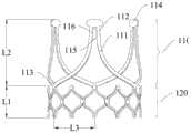
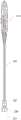
图1a为人工瓣膜的支架的示意图;Fig. 1 a is the schematic diagram of the support of artificial valve;
图1b为图1a所示人工瓣膜的支架的主视图;Fig. 1b is the front view of the bracket of the artificial valve shown in Fig. 1a;
图1c为图1a所示人工瓣膜的支架连接有瓣叶的示意图;Fig. 1c is a schematic diagram showing that the stent of the artificial valve shown in Fig. 1a is connected with leaflets;
图1d为图1a所示人工瓣膜的支架连接有瓣叶的示意图;Fig. 1d is a schematic diagram showing that the stent of the artificial valve shown in Fig. 1a is connected with leaflets;
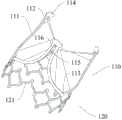
图1e为人工瓣膜的支架的示意图;Figure 1e is a schematic diagram of a stent of an artificial valve;
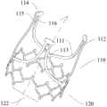
图1f为人工瓣膜的示意图;Figure 1f is a schematic diagram of an artificial valve;
图1g为图1f所示人工瓣膜的示意图;Fig. 1g is a schematic diagram of the artificial valve shown in Fig. 1f;
图1h为人工瓣膜的示意图;Figure 1h is a schematic diagram of an artificial valve;
图1i为图1h中人工瓣膜的爆炸图;Figure 1i is an exploded view of the artificial valve in Figure 1h;
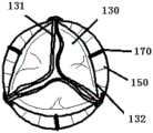
图1j为人工瓣膜中防周漏部的示意图;Fig. 1j is a schematic diagram of the anti-peripheral leakage part in the artificial valve;
图1k为人工瓣膜中防周漏部与内覆膜一体结构的示意图;Fig. 1k is a schematic diagram of the integrated structure of the anti-peripheral leakage part and the inner membrane in the artificial valve;
图2a为持瓣器的示意图;Figure 2a is a schematic diagram of the valve holder;
图2b为持瓣器的示意图;Figure 2b is a schematic diagram of the valve holder;
图2c为图2b中的A-A向剖视图;Figure 2c is a sectional view taken along the line A-A in Figure 2b;
图2d为持瓣器中控制手柄的爆炸图;Figure 2d is an exploded view of the control handle in the valve holder;
图2e为持瓣器中控制手柄的爆炸图(另一视角);Figure 2e is an exploded view (another perspective) of the control handle in the valve holder;
图2f为持瓣器中瓣膜卡扣的示意图(省略套管结构);Figure 2f is a schematic diagram of the valve buckle in the valve holder (the sleeve structure is omitted);
图2g为持瓣器开始装载人工瓣膜的示意图;Fig. 2g is a schematic diagram of the valve holder starting to load the artificial valve;
图2h为持瓣器完全装载人工瓣膜的示意图;Figure 2h is a schematic diagram of the valve holder fully loaded with an artificial valve;
图2i为持瓣器完全装载人工瓣膜且锁定件锁定的示意图;Fig. 2i is a schematic diagram of the valve holder fully loaded with an artificial valve and the locking member locked;
图2j为持瓣器将人工瓣膜置入原生瓣环的示意图;Fig. 2j is a schematic diagram of placing the artificial valve into the native valve annulus by the valve holder;
图2k为持瓣器将人工瓣膜置入原生瓣环,且缝合环完全张开的示意图;Fig. 2k is a schematic diagram of the valve holder inserting the artificial valve into the native valve annulus, and the suture ring is fully opened;
图2l为持瓣器完全释放人工瓣膜的示意图;Figure 21 is a schematic diagram of the valve holder fully releasing the artificial valve;
图2m为人工瓣膜植入人体后的示意图。Fig. 2m is a schematic diagram of the artificial valve implanted in a human body.
图中:110、支撑部;111、U形框;112、结合柱;113、连接端;114、连接耳;115、联络条;116、镂空窗;120、环形部;121、V形框条;122、可扩张区;130、瓣叶;131、游离缘;132、固定缘;140、覆膜;141、内覆膜;142、外覆膜;150、缝合环;151、缝合材料带;160、防周漏部;161、可膨胀材料带;170、穿线标志;In the figure: 110, supporting part; 111, U-shaped frame; 112, connecting column; 113, connecting end; 114, connecting ear; 115, contact bar; 116, hollow window; 120, ring part; 121, V-shaped frame bar ; 122, expandable area; 130, valve leaflet; 131, free edge; 132, fixed edge; 140, covering film; 141, inner covering film; 142, outer covering film; 150, sewing ring; 151, suture material belt; 160. Leakage prevention part; 161. Expandable material belt; 170. Threading mark;
210、控制手柄;211、壳体;212、移动座;213、档位调节机构;214、控制钮;215、卡槽;216、弹性卡舌;217、弹性条;218、导向结构;219、锁定件;220、套筒;221、避让槽;230、瓣膜卡扣;231、适配结构;240、传动件;241、内管;242、外管;250、限位槽。210, control handle; 211, housing; 212, moving seat; 213, gear adjustment mechanism; 214, control button; 215, card slot; 216, elastic tongue; 217, elastic bar; 218, guide structure; Locking part; 220, sleeve; 221, escape groove; 230, valve buckle; 231, adaptation structure; 240, transmission part; 241, inner tube; 242, outer tube;
具体实施方式Detailed ways
下面将结合本申请实施例中的附图,对本申请实施例中的技术方案进行清楚、完整地描述,显然,所描述的实施例仅仅是本申请一部分实施例,而不是全部的实施例。基于本申请中的实施例,本领域普通技术人员在没有做出创造性劳动前提下所获得的所有其他实施例,都属于本申请保护的范围。The following will clearly and completely describe the technical solutions in the embodiments of the application with reference to the drawings in the embodiments of the application. Apparently, the described embodiments are only some of the embodiments of the application, not all of them. Based on the embodiments in this application, all other embodiments obtained by persons of ordinary skill in the art without making creative efforts belong to the scope of protection of this application.
为了更好地描述和说明本申请的实施例,可参考一幅或多幅附图,但用于描述附图的附加细节或示例不应当被认为是对本申请的发明创造、目前所描述的实施例或优选方式中任何一者的范围的限制。In order to better describe and illustrate the embodiments of the application, reference may be made to one or more drawings, but additional details or examples used to describe the drawings should not be regarded as an invention of the application, the presently described implementation limitations on the scope of any of the examples or preferred modes.
需要说明的是,当组件被称为与另一个组件“连接”时,它可以直接与另一个组件连接或者也可以存在居中的组件。当一个组件被认为是“设置于”另一个组件,它可以是直接设置在另一个组件上或者可能同时存在居中组件。It should be noted that when a component is said to be "connected" to another component, it may be directly connected to the other component or intervening components may also exist. When a component is said to be "set on" another component, it may be set directly on the other component or there may be an intervening component at the same time.
除非另有定义,本文所使用的所有的技术和科学术语与属于本申请的技术领域的技术人员通常理解的含义相同。本文中在本申请的说明书中所使用的术语只是为了描述具体的实施例的目的,不是旨在于限制本申请。Unless otherwise defined, all technical and scientific terms used herein have the same meaning as commonly understood by one of ordinary skill in the technical field to which this application belongs. The terms used herein in the specification of the application are only for the purpose of describing specific embodiments, and are not intended to limit the application.
本申请提供了一种人工瓣膜,具有压缩状态和扩张状态,参见图1f、图1g、图1h、图1i所示,包括:The present application provides an artificial valve, which has a compressed state and an expanded state, as shown in Fig. 1f, Fig. 1g, Fig. 1h, and Fig. 1i, including:
支架,支架内部围成血流通道;The stent encloses a blood flow channel inside the stent;
多片瓣叶130,各瓣叶130具有与U形框111相连的固定缘132以及与其他瓣叶130相配合改变血流通道开放程度的游离缘131;A plurality of
覆膜140,包覆于支架径向的内侧和/或外侧;Covering
缝合环150,固定于支架的外周。The
覆膜140包覆于支架径向的内侧和/或外侧。The
植入人体后,缝合环150用于与瓣环缝合,以固定瓣膜位置。After being implanted in the human body, the
在一些实施例中,支架,采用形状记忆合金管材一体切割而成,比如镍钛合金等。该支架可应用于经导管瓣膜置换,还可应用外科瓣中,比如免缝合或通过少量缝合的方式与瓣环固定。例如:采用外科缝合的方式与瓣环固定,继承了外科人工瓣膜的优势,例如,移位风险极低、挡冠脉风险低、可剪除病变的原生瓣叶、适应症广、可以实现瓣中瓣的功能(也即后期瓣膜失效后,可以在瓣膜中置入新的瓣膜)。In some embodiments, the stent is integrally cut from a shape memory alloy tube, such as nickel-titanium alloy. The stent can be applied to transcatheter valve replacement, and can also be applied to surgical valves, such as being suture-free or fixed to the annulus with a small number of sutures. For example: Surgical suture is used to fix the valve annulus, which inherits the advantages of surgical artificial valves, such as extremely low risk of displacement, low risk of blocking coronary arteries, can cut off the diseased original valve leaflets, has wide indications, and can achieve valve function (that is, after the late valve failure, a new valve can be placed in the valve).
人工瓣膜的支架采用镍钛合金材料,径向上可压缩至16mm,降低瓣膜下降至瓣环的难度。在植入时,患者体表的切口长度控制在4~6cm即可满足支架放置的需求,远小于传统外科瓣膜置入所需的20cm的切口长度,减少了缝合次数,节约了阻断时间,减少对患者主动脉根部的损伤。The stent of the artificial valve is made of nickel-titanium alloy material, which can be compressed to 16mm in the radial direction, which reduces the difficulty of the valve descending to the annulus. During implantation, the length of the incision on the patient's body surface can be controlled at 4-6cm to meet the needs of stent placement, which is much smaller than the 20cm incision length required for traditional surgical valve placement, which reduces the number of sutures and saves the blocking time. Reduces damage to the patient's aortic root.
除此之外,小切口可选择肋间入路,避免了正中切开胸骨对患者造成的痛苦,此外对于窦管结合部直径较小的患者,降低了植入的难度。In addition, the intercostal approach can be selected for the small incision, which avoids the pain caused by the median sternotomy to the patient. In addition, for patients with a small diameter of the sinotubular junction, the difficulty of implantation is reduced.
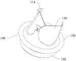
支架,具有压缩状态和展开状态下的膨胀状态。参见图1a、图1b所示,支架,处于膨胀状态,具有相对的流入侧和流出侧,包括:The stent has an expanded state in a compressed state and an expanded state. Referring to Fig. 1a and Fig. 1b, the stent, in an expanded state, has opposite inflow sides and outflow sides, including:
支撑部110,由多个U形框111围成且各U形框111的开口朝向流出侧(图1a中虚线为血液流动方向),相邻两U形框111的侧边彼此邻近形成结合柱112,相邻两U形框111的侧边交汇至结合柱112的顶端;The
环形部120,为在径向上可形变的网格结构,且整体上位于支撑部110的流入侧,环形部120与支撑部110之间的连接部位为多处,且分别与各U形框111中处在流入侧的底部(在本实施例中,为U形的转折部位,即:U形部的最低点处)相对应。The
环形部120在径向上为可形变的网格结构,网格结构是从整体上而言,并不严格要求在周向上的各部位均具有完整的网格。The
由于环形部120在径向上具有可形变的空间,使人工瓣膜支架在径向上可进行一定程度的压缩,在采用外科手术进行人工瓣膜植入的过程中,可将人工瓣膜支架进行压缩状态,相比现有的外科瓣膜置换术,由于瓣膜被极大程度的进行了压缩,使得手术的视野更加开阔。Since the
参见图1a、图1b、图2h所示,支架具有相对的装载状态和释放状态,其中:Referring to Fig. 1a, Fig. 1b, Fig. 2h, the support has a relative loaded state and a released state, wherein:
在装载状态下,支撑部110的流出侧径向向内聚拢,环形部120整体上朝向流入侧扩口,支架被压缩;In the loaded state, the outflow side of the
在释放状态下,支撑部110的流出侧径向向外扩张,支架整体上为直筒结构,此时支架处于膨胀状态,未被压缩。In the released state, the outflow side of the
图1a、图1b中,人工瓣膜的支架处于释放状态(膨胀状态),支架整体上为直筒结构,图2h中,人工瓣膜的支架处于装载状态,支撑部110的U形框111侧边相互靠拢,形成向内聚拢的结构,环形部120适应性的朝向流出侧扩口。In Fig. 1a and Fig. 1b, the stent of the artificial valve is in the released state (inflated state), and the stent is a straight cylindrical structure as a whole. In Fig. 2h, the stent of the artificial valve is in the loading state, and the sides of the
在一些实施例中,支架为一体结构,且采用可自膨释放的记忆材料。例如采用镍钛合金的管材切割,再经过热处理定型,得到支架。In some embodiments, the stent has a one-piece structure and adopts a self-expandable and releasable memory material. For example, a pipe made of nickel-titanium alloy is cut, and then heat-treated to obtain a stent.
支架具有可扩张结构,同时采用镍钛材质,可利用支架的径向支撑力进行锚定,不需要球囊扩张,减少手术操作的复杂程度。The stent has an expandable structure and is made of nickel-titanium material, which can be anchored by the radial support force of the stent without the need for balloon expansion, reducing the complexity of surgical operations.
参见图1a、图1b所示,U形框111为三个,各U形框111中处在流入侧的底部为连接端113,环形部120通过对应位置的网格结构顶点与各连接端113相固定。Referring to Fig. 1a and Fig. 1b, there are three
流入侧的底部也即U形框111底部的中间位置定义为连接端113,连接端113与环形部120的网格结构顶点固定连接。The bottom of the inflow side, that is, the middle position of the bottom of the
在一些实施例中,U形框111的框条强度大于环形部120的框条强度。In some embodiments, the frame strength of the
瓣膜的流出侧为瓣叶工作区,也即U形框111作为瓣叶130活动时最直接的支撑,U形框111的框条强度大于环形部120的框条强度,在瓣叶130开闭时,U形框111具有更高的强度不易发生形变,减少摆动,同时减小对环形部120的影响,增强支架的耐久性。The outflow side of the valve is the working area of the leaflet, that is, the
在植入时,环形部120的网格结构主要起锚定作用,锚定在人体心脏瓣膜的瓣环处。在保证人工心脏瓣膜径向支撑力的前提下,环形部120的框条强度小于U形框111的框条强度,可以使环形部120在受到外力压迫时,通过自身发生形变顺应外力,减小对支撑部110的U形框111的影响。When implanted, the grid structure of the
为了实现框条强度的差异,U形框111的框条可以相较于环形部120的框条更宽或更厚,考虑加工的便捷,优选的,U形框111的框条可以相较于环形部120的框条更宽。In order to realize the difference in frame strength, the frame bars of the
在其中一实施例中,参见图1a、图1b所示,结合柱112的顶端在支架周向上加宽构成用于与输送系统相适配的连接耳114。In one embodiment, as shown in FIG. 1 a and FIG. 1 b , the top end of the
连接耳114用于将人工瓣膜的支架与输送系统连接,使支架稳定安装在输送系统中。结合柱112顶端在支架周向上加宽形成T形结构,T形结构的横直部为连接耳114。连接耳114可以采用多种结构,除图1a、图1b中所示的大致呈矩形的结构外,也可以采用其他的形式,例如半圆形。The connecting
在其中一实施例中,参见图1a、图1b所示,相邻两U形框111的侧边之间设置有一个或多个联络条115,联络条115在所在的结合柱112部位围成一个或多个镂空窗116。In one of the embodiments, as shown in Fig. 1a and Fig. 1b, one or more contact strips 115 are arranged between the sides of two adjacent
联络条115在相邻两U形框111的侧边之间形成连接结构,一方面加强相邻两U形框111侧边之间的连接强度,另一方面也不过分干涉U形框111侧边的形变。The connecting
瓣叶130在缝制过程中,具有一包裹U形框111部分侧边的翻边,至少一个镂空窗116用于容纳瓣叶130的翻边。During the sewing process, the
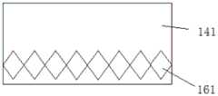
在其中一实施例中,参见图1b所示,沿支架轴向,环形部120的长度为L1,支撑部110的长度为L2,且L1小于L2。In one embodiment, as shown in FIG. 1b , along the axial direction of the stent, the length of the
支撑部110用于固定瓣叶130,至少具有与瓣叶130相适应的轴向长度,而环形部120用于在血管中定位以及承载防瓣周漏的结构,由于采用外科手术的方式,人工瓣膜缝合在瓣环上,环形部120容易满足定位的需要,不需要过长的轴向长度,同时,承载防瓣周漏结构也不需要过长的轴向长度,因此,在满足使用需求的前提下,尽可能的减少轴向长度,减少对植入部位组织的不良影响。The supporting
在其中一实施例中,参见图1b所示,L1:L2=1:1.5~1:3。In one embodiment, as shown in FIG. 1b, L1:L2=1:1.5˜1:3.
在其中一实施例中,参见图1a、图1b所示,环形部120在周向上的至少一部分为V形框条121。In one embodiment, as shown in FIG. 1 a and FIG. 1 b , at least a part of the
V形框条121在受到外力作用力,更容易发生形变,也V形夹角度数发生改变,在需要进行瓣中瓣植入时,V形框条121的存在,使环形部120受到径向外力作用时,在周向上更容易向外扩张,利于新瓣膜的植入。The V-shaped
环形部120在径向受力向外扩张时,通过V型框条顺应外力,减少对支撑部110的影响,也即减少对支撑部110上连接的瓣叶130形态的影响。When the
可采用自膨瓣和球扩瓣作为瓣中瓣植入,由于支架的V形框条121受到外力作用可扩张,因此植入自膨瓣后,可以将小切口瓣膜撑开且不回弹,保证了开口面积不受影响。Self-expanding valves and ball-expanding valves can be used as valve-in-valve implants. Since the V-shaped
在其中一实施例中,参见图1a、图1b所示,环形部120的网格结构为沿周向排布的单元格,单元格在轴向上仅为一圈。In one embodiment, as shown in FIG. 1 a and FIG. 1 b , the grid structure of the
环形部120在轴向上的尺寸较短,仅设置一圈单元格,减少单元格的密度,使环形部120在受到径向外力作用时,更容易发生形变,由于采用外科手术的方式植入瓣膜,瓣膜与瓣环之间存在缝合,环形部120易于形变不会对定位产生不利影响,而且在需要进行瓣中瓣植入时,更容易周向扩张,利于新瓣膜的植入。The size of the
在其中一实施例中,参见图1a、图1b所示,所有单元格的数量为9~24个,且为U形框111数量的整数倍。In one embodiment, as shown in FIG. 1a and FIG. 1b , the number of all cells is 9-24, which is an integer multiple of the number of
每个U形框在支架圆周向上横跨单元格的数量为3~6个。参见图1b所示,每个U形框在支架圆周向上横跨单元格的数量为5个。图1b中,L3为半个U形框在支架圆周向上的投影长度,恰好对应2.5个单元格,通过简单的换算,可得一个U形框在支架圆周向上的投影长度,恰好对应5个单元格,也即每个U形框在支架圆周向上横跨单元格的数量为5个。Each U-shaped frame spans 3 to 6 cells in the circumferential direction of the support. Referring to Fig. 1b, each U-shaped frame spans five cells in the circumferential direction of the support. In Figure 1b, L3 is the projected length of half a U-shaped frame on the circumference of the support, which corresponds to exactly 2.5 units. Through simple conversion, the projected length of a U-shaped frame on the circumference of the support can be obtained, which corresponds to exactly 5 units. grid, that is, the number of cells that each U-shaped frame spans across the circumference of the bracket is 5.
所有单元格沿周向均匀排布,或至少分为N组,N为U形框111数量,各组数量相同。所有单元格的数量为12个,每个单元格并不严格为完整的周向封闭的结构,可以在周向上开放。All the cells are uniformly arranged along the circumference, or at least divided into N groups, where N is the number of
在其中一实施例中,参见图1b所示,环形部120在展平状态下,各单元格具有相同的轴向高度。各单元格的轴向高度相同,即指各单元格自身在支架轴向上的尺寸相同,也包含各单元在支架轴向上的位置相同。环形部120的各单元格流出侧的顶点共面,且该面垂直于支架的轴向。In one embodiment, as shown in FIG. 1 b , when the
环形部120仅部分单元格与U形框111的连接端113连接,其余单元格不与U形框111连接,U形框111侧边与环形部120之间的形变相对独立。Only part of the cells of the
在其中一实施例中,参见图1a、1b所示,至少一个单元格为开放于环形部120的流入侧的形变释放格。In one embodiment, as shown in FIGS. 1 a and 1 b , at least one unit cell is a deformation releasing cell opened on the inflow side of the
V形框条121即为形变释放格,在受到径向外力的作用下,形变释放格优先发生形变,以顺应外力,其余周向封闭的单元格后续发生形变。The V-shaped
在其中一实施例中,参见图1a、1b所示,除形变释放格外,其余各单元格大致为菱形或六边形。单元格为菱形或六边形,相邻单元格之间通过单元格的顶点相连。In one embodiment, as shown in FIGS. 1 a and 1 b , except for the deformation release cell, the other cells are roughly rhombus or hexagon. The cells are diamond-shaped or hexagonal, and adjacent cells are connected by the vertices of the cells.
单元格的形状并非严格的几何形状,基于加工的需要存在局部的变形,但至少应满足支架径向收缩和扩展的需求。The shape of the cell is not a strict geometric shape, and there are local deformations based on the needs of processing, but at least it should meet the requirements of radial contraction and expansion of the scaffold.
在其中一实施例中,参见图1a所示,形变释放格的数量以及周向位置与结合柱112一一对应。形变释放格的数量与结合柱的数量相同,且形变释放格和结合柱在支架的轴向上对齐。In one embodiment, as shown in FIG. 1 a , the number and circumferential positions of the deformation release cells correspond to the
形变释放格与结合柱112的位置一一对应,在受到外力作用时,环形部120与支撑部110中发生周向扩张的部位在轴向上相互对齐,环形部120和支撑部110的形变相互之间牵制较少,也即环形部120周向扩张时,不会被支撑部110牵制,反之同理。The positions of the deformation release cells and the coupling posts 112 correspond one by one. When an external force is applied, the circumferentially expanded parts of the
在其中一实施例中,参见图1a所示,形变释放格为V形框条121,且V形的开口朝向环形部120的流入侧。In one embodiment, as shown in FIG. 1 a , the deformation releasing grid is a V-shaped
V形的开口朝向环形部120的流入侧,在受到径向外力作用时,V形的开口更容易扩张。The V-shaped opening faces the inflow side of the
在其中一实施例中,参见图1f所示,支架的外周围绕有环形的防周漏部160,防周漏部160处在缝合环150的流入侧。In one embodiment, as shown in FIG. 1 f , an annular
参见图1f所示,缝合环150沿支架周向延伸且具有波浪结构,相对处在流入侧的部位为波谷,相对处在流出侧的部位为波峰,波谷与防周漏部160相贴靠。As shown in FIG. 1f, the
瓣膜植入后,一方面依靠支架自身的可扩张结构进行锚定,另一方面缝合环150与瓣环之间进行缝合,保证瓣膜植入后的稳定性,同时,防周漏部160可起到封堵瓣环和缝合环150间隙的作用,防止血液经由间隙流动。After the valve is implanted, on the one hand, rely on the expandable structure of the stent itself for anchoring, and on the other hand, suture between the
在其中一实施例中,参见图1f所示,缝合环150处在U形框111的流入侧,且与U形框111之间留有间隔区。In one embodiment, as shown in FIG. 1 f , the
间隔区一方面便于覆膜140以及瓣叶130的缝制,另一方面也给予缝合环150一定的形变空间,即人工瓣膜压缩后进入持瓣器中时,缝合环150的形变不会给瓣叶130带来较大的形变压力。On the one hand, the spacer facilitates the sewing of the
在其中一实施例中,参见图1f、图1g、图1h、图1i所示,覆膜140包括外覆膜142,且包覆于支架径向的外侧,防周漏部160包括可膨胀材料带161以及外覆膜142的第一部分,且第一部分包裹可膨胀材料带161。In one of the embodiments, as shown in Fig. 1f, Fig. 1g, Fig. 1h, and Fig. 1i, the covering
在其中一实施例中,参见图1f、图1g、图1h、图1i所示,缝合环150包括缝合材料带151以及外覆膜142的第二部分,且第二部分包裹缝合材料带151。In one embodiment, as shown in FIGS. 1f , 1g , 1h , and 1i , the
外覆膜142除第一部分和第二部分外,还可以具有其他的部分。外覆膜142为一整体,其中第一部分包裹可膨胀材料带161,第二部分包裹缝合材料带151,减少外覆膜142的拼接,一方面便于加工,另一方面也减少材料泄露。The
缝合材料带151可以采用硅橡胶材质,具有适度的弹性,减小对瓣环的刚性挤压,同时便于缝合过程的进行,人工瓣膜通过3个缝合点缝制瓣环上,减少了瓣膜移位的风险,缝合环150与原生瓣环之间也能够很好的贴合,一定程度上,减少瓣周漏。The
在其中一实施例中,参见图1f、图1g、图1h、图1i所示,覆膜140包括内覆膜141,且包覆于支架径向的内侧,内覆膜141的流出侧对接至瓣叶130的固定缘132,内覆膜141和外覆膜142两者交汇连接于支架的流入侧。In one of the embodiments, as shown in Fig. 1f, Fig. 1g, Fig. 1h, and Fig. 1i, the covering
内覆膜141和外覆膜142将支架整体包裹,减少裸露部分。The
内覆膜141和外覆膜142两者为一体膜片,或为分体膜片。Both the
内覆膜和外覆膜采用不同材质或相同材质。The inner covering film and the outer covering film are made of different materials or the same material.
在其中一实施例中,内覆膜141采用PU材质,外覆膜采用PET材质(PET织物)。In one embodiment, the
分体膜片之间的拼缝位于支架的流入侧,或位于支架径向的外侧,或位于支架径向的内侧。The seam between the split diaphragms is located on the inflow side of the stent, or on the radially outer side of the stent, or on the radially inner side of the stent.
在其中一实施例中,参见图1f、图1g、图1h、图1i所示,可膨胀材料带161以及缝合材料带151各自独立的被外覆膜142完全包裹,或被夹持包裹在内覆膜141和外覆膜142之间。In one of the embodiments, as shown in FIG. 1f, FIG. 1g, FIG. 1h, and FIG. 1i, the
参见图1i所示,缝合材料带151沿支架周向延伸且具有波浪结构,内覆膜141和外覆膜142在包裹缝合材料带151时,不改变缝合材料带的波浪构型,因此,得到的缝合环150也具有与缝合材料带151一致的波浪结构,相对处在流入侧的部位为波谷,相对处在流出侧的部位为波峰,波谷与防周漏部160相贴靠。Referring to Fig. 1i, the
可膨胀材料带161可以采用PU发泡材料,PU发泡材料具有弹性好,不透水的特点,有利于与瓣环紧密贴合,减少瓣周漏。The
在其中一实施例中,参见图1f、图1g、图1h、图1i所示,可膨胀材料带161包括绕支架外围布置的基底以及固定于基底上的吸水膨胀材料。In one embodiment, as shown in Fig. 1f, Fig. 1g, Fig. 1h, and Fig. 1i, the
基底和吸水膨胀材料采用聚合物材料制成,例如,以下材料的一种或多种构成:聚酯、聚对苯二甲酸乙二酯(PET)、聚醚醚酮(PEEK)、聚丙烯(PP)、聚四氟乙烯(PTFE)、聚氨酯(PU)、超高分子量聚乙烯(UHMWPE)、硅酮、聚甲醛、聚苯砜、聚砜、聚偏二氟乙烯、聚酰胺。基底可采用PET等高分子材料,吸水膨胀材料可采用水凝胶等遇水膨胀的材料或多孔发泡材料。在其中一实施例中,参见图1f、图1g、图1h、图1i、图1j所示,吸水膨胀材料呈带状且在支架周向上连续分布,或为间隔布置的多个的块状;环形部120具有网格结构,块状的吸水膨胀材料分别处对应网格结构的镂空区。The substrate and water-swellable material are made of polymeric materials, for example, one or more of the following materials: polyester, polyethylene terephthalate (PET), polyetheretherketone (PEEK), polypropylene ( PP), polytetrafluoroethylene (PTFE), polyurethane (PU), ultra-high molecular weight polyethylene (UHMWPE), silicone, polyoxymethylene, polyphenylsulfone, polysulfone, polyvinylidene fluoride, polyamide. The substrate can use polymer materials such as PET, and the water-swellable material can use water-swellable materials such as hydrogel or porous foam materials. In one of the embodiments, as shown in Fig. 1f, Fig. 1g, Fig. 1h, Fig. 1i, and Fig. 1j, the water-absorbing swelling material is in the shape of a strip and is continuously distributed in the circumferential direction of the stent, or is in the shape of a plurality of blocks arranged at intervals; The
吸水膨胀材料为间隔布置的多个块状,块状的吸水膨胀材料相对于支架朝向支架径向外侧凸起。The water-absorbing swellable material is a plurality of blocks arranged at intervals, and the block-shaped water-absorbed swellable material protrudes toward the radially outer side of the stent relative to the stent.
在其中一实施例中,参见图1j所示,防周漏部160包括可膨胀材料带以及内覆膜141的一部分,可膨胀材料带161附着于内覆膜141上。In one embodiment, as shown in FIG. 1 j , the
在其中一实施例中,内覆膜141采用可膨胀材料,可膨胀材料带161与内覆膜141为一体结构。In one embodiment, the
在其中一实施例中,参见图1j所示,可膨胀材料带161连接于内覆膜141的流入侧,且为沿支架周向间隔布置的多个的块状,环形部具有网格结构,块状的吸水膨胀材料分别处对应网格结构的镂空区。In one of the embodiments, as shown in FIG. 1j, the
在其中一实施例中,参见图1f、图1g、图1h、图1i所示,缝合环150上带有穿线标志170,在支架周向上,穿线标志170与结合柱112错位布置。也即,在支架周向上,相邻两结合柱112中间位置设置穿线标志170。In one embodiment, as shown in Fig. 1f, Fig. 1g, Fig. 1h, and Fig. 1i, the
在其中一实施例中,参见图2h、图2i所示,图中虚线为血流方向,装载状态下,缝合环150呈沿支架周向延伸的波浪结构:In one of the embodiments, as shown in Fig. 2h and Fig. 2i, the dotted line in the figure is the direction of blood flow. In the loaded state, the
相对处在流入侧的部位为波谷;The part on the inflow side is the trough;
相对处在流出侧的部位为波峰。The part on the outflow side is the peak.
支架在装载状态下和释放状态下均具有波浪结构,区别在于波峰和波谷的高度差不同。The bracket has a wave structure both in the loaded state and the released state, the difference lies in the difference in height between the crests and troughs.
在其中一实施例中,参见图2h、图2i所示,缝合环150上带有穿线标志170,装载状态下,穿线标志170处在波谷位置。In one embodiment, as shown in FIG. 2h and FIG. 2i , there is a
本申请还提供了一种植入后可扩张的人工心脏瓣膜,人工心脏瓣膜具有植入状态和植入后扩张状态,其中,植入状态人工心脏瓣膜具有第一尺寸,植入后扩张状态人工瓣膜具有第二尺寸,第二尺寸大于第一尺寸;The present application also provides an artificial heart valve expandable after implantation. The artificial heart valve has an implanted state and an expanded state after implantation, wherein the artificial heart valve in the implanted state has a first size, and the artificial heart valve in the expanded state after implantation having a second size, the second size being greater than the first size;
人工心脏瓣膜具有相对的流入侧和流出侧,人工心脏瓣膜包括支架,参见图1a和1e所示,支架包括:The artificial heart valve has opposite inflow side and outflow side, and the artificial heart valve comprises a stent, see Fig. 1a and 1e shown, and stent comprises:
支撑部110,由多个U形框111围成且各U形框111的开口朝向流出侧,相邻两U形框111的侧边彼此邻近形成结合柱112,相邻两U形框111的侧边交汇至结合柱112的顶端;The
环形部120,为在径向上可形变的网格结构,且整体上位于支撑部110的流入侧,环形部120在周向上的至少一部分为可扩张区122,该可扩张区122的位置与结合柱112的流入侧在支架轴向上对齐。The
本申请提供的人工心脏瓣膜可以用于瓣中瓣手术,瓣中瓣是指将一个新的瓣膜部署在另一个失效的植入瓣膜中。为了在失效的植入瓣膜内放入新的瓣膜,有必要对失效的植入瓣膜进行进一步的扩张,使其扩张到一定程度,以便放置一个与失效瓣膜同等型号或者下一个尺寸的新瓣膜,以增加植入后瓣膜的有效开口面积。The artificial heart valve provided by the present application can be used in valve-in-valve surgery, which refers to the deployment of a new valve in another failed implanted valve. In order to place a new valve in the failed implanted valve, it is necessary to further dilate the failed implanted valve to a certain extent so that a new valve of the same type or the next size as the failed valve can be placed, To increase the effective opening area of the implanted valve.
在本发明中,支架的环形部为可形变网格结构,具有周向上的形变能力,加上通过在环形部设置可扩张区122,使得在瓣中瓣手术,能进行充分扩张,以满足瓣中瓣手术的需求。In the present invention, the annular part of the stent is a deformable grid structure, which has the ability to deform in the circumferential direction. In addition, by setting the
所述人工心脏瓣膜的植入状态是指人工心脏瓣膜植入人体后,正常工作的状态,所述人工心脏瓣膜的植入后扩张状态,是指需要进行瓣中瓣手术时,对该瓣膜进行扩张后的状态。The implantation state of the artificial heart valve refers to the normal working state after the artificial heart valve is implanted into the human body, and the expanded state of the artificial heart valve after implantation refers to the valve-in-valve operation. state after expansion.
植入状态人工心脏瓣膜具有第一尺寸,植入后扩张状态人工瓣膜具有第二尺寸,第二尺寸比第一尺寸大1~4mm。人工心脏瓣膜整体呈圆柱形结构,第一尺寸和第二尺寸均为圆柱形结构的直径,由于人工心脏瓣膜上还具有覆膜等柔性结构,在提及圆柱形结构的直径时不容易准确测量,也可以第一尺寸和第二尺寸定义为人工心脏瓣膜支架的直径。The artificial heart valve in the implanted state has a first size, and the artificial valve in the expanded state after implantation has a second size, and the second size is 1-4 mm larger than the first size. The artificial heart valve has a cylindrical structure as a whole, and the first dimension and the second dimension are both the diameter of the cylindrical structure. Since the artificial heart valve also has a flexible structure such as a membrane, it is not easy to accurately measure the diameter of the cylindrical structure. , may also be defined as the diameter of the artificial heart valve stent by the first dimension and the second dimension.
第二尺寸比第一尺寸大1~4mm,既可以实现瓣中瓣的植入需求,可扩张区122相对于环形部120的其他部位,在径向受力时,更容易发生形变,向外扩张,由于采用外科手术的方式植入瓣膜,瓣膜与瓣环之间存在缝合,环形部120易于形变不会对定位产生不利影响,而且在需要进行瓣中瓣植入时,更容易周向扩张,利于新瓣膜的植入。The second size is 1-4 mm larger than the first size, which can realize the implantation requirements of the valve in the valve. Compared with other parts of the
可扩张区122位于环形部的流入侧,可扩张区122的位置与结合柱112的流入侧对正,在受到外力作用时,环形部120与支撑部110中发生周向扩张的部位在轴向上相互对齐,环形部120和支撑部110的形变相互之间牵制较少,也即环形部120周向扩张时,不会被支撑部110牵制,反之同理。The
环形部120在径向受力向外扩张时,通过可扩张区122顺应外力,减少对支撑部110的影响,也即减少对支撑部110上连接的瓣叶130形态的影响。When the
在其中一实施例中,参见图1e所示,可扩张区122为在支架周向上可伸展的框条结构,且框条结构所围成的区域为开放区。In one embodiment, as shown in FIG. 1 e , the
可扩张区122采用周向可伸展的框条结构,在受到径向外力作用时,框条结构伸展使可扩张区122发生形变,开放区的设置允许更大的形变量。The
在其中一实施例中,参见图1e所示,框条结构为V形或W形。In one embodiment, as shown in FIG. 1 e , the frame structure is V-shaped or W-shaped.
V形的框条结构不需要球囊进行扩张,利用V形框条121结构本身的径向支撑力,与患者原生主动脉瓣环紧密贴合,增强了瓣膜稳定性,减少了瓣周漏,降低了手术操作的复杂度。The V-shaped frame structure does not require a balloon to expand, and uses the radial support force of the V-shaped
在其中一实施例中,参见图1e所示,可扩张区122的数量以及周向位置与结合柱112一一对应。可扩张区122的数量与结合柱112的数量相同,且可扩张区122和结合柱112在支架的轴向上对齐。In one embodiment, as shown in FIG. 1 e , the number and circumferential positions of the
可扩张区122与结合柱112的位置一一对应,在受到外力作用时,环形部120与支撑部110中发生周向扩张的部位在轴向上相互对齐,环形部120和支撑部110的形变相互之间牵制较少,也即环形部120周向扩张时,不会被支撑部110牵制,反之同理。The position of the
本申请还提供了一种人工瓣膜的加工方法,包括:The application also provides a method for processing an artificial valve, including:
S100、将各瓣叶与支架径向内侧覆膜的流出侧边缘连接,形成第一预制品;S100. Connect each valve leaflet to the outflow side edge of the radially inner coating of the stent to form a first preform;
S200、利用支架径向外侧覆膜形成第二预制品;S200. Forming a second preform by using a coating film on the radially outer side of the stent;
S300、将所述第一预制品和所述第二预制品分别连接至支架形成所述人工瓣膜。S300. Connect the first preform and the second preform to a bracket respectively to form the artificial valve.
在其中一实施例中,S100,利用支架径向内侧覆膜附着防周漏材料形成防周漏部,或利用支架径向内侧覆膜褶皱形成防周漏部。In one embodiment, in S100, the anti-peripheral leakage part is formed by adhering the anti-circumferential leakage material to the radially inner membrane of the stent, or forming the anti-circumferential leakage part by using the folds of the radially inner membrane of the stent.
在其中一实施例中,S200,利用支架径向外侧覆膜的第一部分包裹缝合材料,形成第二预制品。In one embodiment, S200, wrapping the suture material with the first part of the radially outer membrane of the stent to form a second preform.
在其中一实施例中,S200,利用支架径向外侧覆膜的第二部分包裹防周漏材料,形成第二预制品。In one of the embodiments, S200, using the second part of the radially outer covering film of the stent to wrap the anti-circumferential leakage material to form a second preform.
在其中一实施例中,S200,利用支架径向外侧覆膜的褶皱形成缝合部和/或防周漏部,形成第二预制品。In one embodiment, at S200 , the seam portion and/or the peripheral leakage prevention portion are formed by using the folds of the covering film on the radially outer side of the stent to form a second preform.
在其中一实施例中,人工瓣膜的加工方法,步骤S300包括:In one of the embodiments, the processing method of the artificial valve, step S300 includes:
S310、将第一预制品缝缀连接至支架,且在邻近结合柱112的顶端部位预留有第一非缝合区;S310, stitching and connecting the first preform to the bracket, and reserving a first non-sewing area near the top of the
S320、将第二预制品缝缀连接至支架,且在邻近结合柱112的顶端部位预留有第二非缝合区;S320, stitching and connecting the second preform to the bracket, and reserving a second non-sewing area near the top of the
S330、将第一非缝合区和第二非缝合区连同支架一并缝缀彼此固定。S330. Sewing the first non-sewing area and the second non-sewing area together with the support to fix each other.
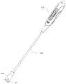
为了将人工瓣膜递送至体内,本申请还提供了一种持瓣器,参见图2a、图2b、图2c、图2f所示,持瓣器,包括:In order to deliver the artificial valve into the body, the present application also provides a valve holder, as shown in Figure 2a, Figure 2b, Figure 2c, and Figure 2f, the valve holder includes:
控制手柄210,具有相对的远端和近端;a
瓣膜卡扣230,自身的外周具有与人工瓣膜相应的适配结构231;The
套筒220,活动设置在瓣膜卡扣230的外周,套筒220可在包裹和暴露适配结构231这两种状态间切换;The
两传动件240,内外嵌套配合且远端分别连接瓣膜卡扣230和套筒220,两传动件240的近端连接至控制手柄210、且至少一者与控制手柄210之间活动配合以适应套筒220的状态切换。Two
控制手柄210的近端为靠近操作者的一端,远端为远离操作者的一端。The proximal end of the control handle 210 is the end close to the operator, and the distal end is the end far away from the operator.
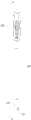
持瓣器将人工瓣膜收缩至小尺寸状态,并将其输送至目标位置,参见图2g、图2h所示,在手术进行前,将人工瓣膜与瓣膜卡扣230通过适配结构231相连接,通过操作控制手柄210,使套筒220从暴露适配结构231切换至包裹适配结构231,人工瓣膜在径向被压缩而减小尺寸,以适应小切口位置的置入。The valve holder shrinks the artificial valve to a small size and transports it to the target position, as shown in Fig. 2g and Fig. 2h. Before the operation, the artificial valve is connected with the
持瓣器中仅套筒220和瓣膜卡扣230与人工瓣膜位置靠近,且遮挡有限,控制手柄210远离人工瓣膜,不容易阻挡术者的视线,便于在输送瓣膜的过程中观察瓣膜的状态。In the valve holder, only the
压缩在套管中的人工瓣膜尺寸较小,更容易通过窦管交界,且在输送过程中部会影响术者视野。The prosthetic valve compressed in the sleeve is smaller in size, easier to pass through the sinotubular junction, and will affect the operator's field of view during delivery.
持瓣器的工作过程参见图2g~图2m所示,具体如下:The working process of the valve holder is shown in Figure 2g to Figure 2m, and the details are as follows:
参见图2g所示,套筒220暴露瓣膜卡扣230的适配结构231,人工瓣膜与瓣膜卡扣230的适配结构231相结合;Referring to Fig. 2g, the
参见图2h所示,通过控制手柄210操作套筒220包裹适配结构231,人工瓣膜处于压缩状态;As shown in FIG. 2h, the
参见图2i所示,通过控制手柄210锁定套筒220位置;Referring to Fig. 2i, the position of the
参见图2j所示,术者将缝线穿过原生瓣环,并将缝线穿过压缩状态的人工瓣膜的缝合环150,将压缩后的人工瓣膜沿缝线移动递送至原生瓣环;Referring to Fig. 2j, the operator passes the suture through the original valve annulus, and passes the suture through the
参见图2k所示,通过控制手柄210解除套筒220位置的锁定,并操作套筒220由包裹适配结构231的状态切换至暴露适配结构231的状态,人工瓣膜释放,并逐渐由装载状态切换至释放状态;Referring to Fig. 2k, by controlling the
参见图2l所示,人工瓣膜完全脱离瓣膜卡扣230,恢复至原始尺寸;As shown in Figure 2l, the artificial valve is completely detached from the
参见图2m所示,人工瓣膜完全释放后置于原生瓣环处,将原生瓣环与人工瓣膜的缝合环150进行缝合,撤离持瓣器。Referring to Fig. 2m, after the artificial valve is fully released, it is placed on the native valve annulus, the original valve annulus and the
为了避免影响术者的视野,套筒220可以采用透明材质。In order to avoid affecting the operator's field of vision, the
两传动件在轴向上可相对滑动,以实现套筒220包裹和暴露适配结构231两种状态的切换。其中一传动件相对控制手柄210固定,另一传动件可沿轴向移动,可沿轴向移动的传动件可以与套筒220联动,或者与瓣膜卡扣230联动。The two transmission parts can slide relative to each other in the axial direction, so as to realize the switch between the two states of the
在其中一实施例中,参见图2a、图2b、图2c所示,套筒220的远端为扩口结构,扩口结构的开口边缘设有沿周向间隔布置的多个避让槽221。In one embodiment, as shown in FIG. 2a , FIG. 2b , and FIG. 2c , the distal end of the
参见图2h所示,在人工瓣膜发生压缩时,避让槽221可以容纳缝合环150的褶皱,减少压缩后人工瓣膜的径向尺寸。Referring to Fig. 2h, when the artificial valve is compressed, the
在其中一实施例中,参见图2a、图2f所示,图2f中省略了套筒220结构,展示内部的瓣膜卡扣230结构,瓣膜卡扣230为柱状,适配结构231为设置在瓣膜卡扣230外周的防脱槽和/或防脱柱,避让槽221的周向分布位置与适配结构231相对应。In one of the embodiments, as shown in Fig. 2a and Fig. 2f, the structure of the
适配结构231为了将人工瓣膜稳定的保持在瓣膜卡扣230上,瓣膜卡扣230与人工瓣膜的适配结构231为互补的结构,例如,人工瓣膜上设置防脱耳,则瓣膜卡扣230上设置与防脱耳形状相应的防脱槽;人工瓣膜上设置防脱槽,则瓣膜卡扣230上设置与防脱槽形状相应的防脱柱。The
避让槽221的周向分布位置与适配结构231相对应,是基于人工瓣膜压缩后的状态考虑,使避让槽221更好的容纳人工瓣膜的褶皱部位。The circumferential distribution position of the
控制手柄210包括:Control handle 210 includes:
壳体211,壳体211内为安装室,两传动件中的一者固定至安装室内;
移动座212,滑动设置在安装室内,两传动件中的另一者固定至移动座212;The moving
档位调节机构213,配置在移动座212和安装室之间,将移动座212限制于至少两个档位;The
控制钮214,与移动座212相连、且至少一部分延伸至壳体211的外部。The
在其中一实施例中,参见图2d、图2e所示,控制手柄210包括:In one of the embodiments, as shown in Fig. 2d and Fig. 2e, the control handle 210 includes:
壳体211,壳体211内为安装室,其中一传动件固定至安装室内;
移动座212,滑动设置在安装室内,另一传动件固定至移动座212;The moving
档位调节机构213,配置在移动座212和安装室之间,将移动座212限制于至少两个档位;The
控制钮214,与移动座212相连、且至少一部分延伸至壳体211的外部。The
控制钮214与移动座212相连,通过拨动控制钮214可以操作移动座212移动,移动座212移动至档位调节机构213对应的档位处会被限制移动,除非通过控制钮214施加外力克服这种限制。The
档位调节机构213具有至少两个档位,至少两个档位分别对应下列位置:The
a)人工瓣膜完全压缩的位置;a) The fully compressed position of the prosthetic valve;
b)人工瓣膜完全释放的位置。b) The position where the prosthetic valve is fully released.
除此之外,还可以设置的档位对应人工瓣膜释放过程中不同状态的位置,例如,针对人工瓣膜中缝合环完全张开的状态设置相应的档位,人工瓣膜的缝合环保持在完全张开的状态时,利用缝线将缝合环和原生瓣环进行缝合,缝合完毕后,将人工瓣膜完全释放,撤回持瓣器。In addition, the stalls that can also be set correspond to the positions of different states during the release process of the artificial valve. For example, the corresponding stalls are set for the fully opened state of the sewing ring in the artificial valve. In the open state, the suture ring and the original valve ring are sutured. After the suture is completed, the artificial valve is completely released and the valve holder is withdrawn.
人工瓣膜的完全压缩并非指人工瓣膜可能的最大程度的压缩状态,而是指人工瓣膜在持瓣器中所需达到的最终压缩状态。The complete compression of the artificial valve does not refer to the maximum possible compression state of the artificial valve, but refers to the final compression state that the artificial valve needs to achieve in the valve holder.
通过档位调节机构213对移动座212进行限位,可以避免术者在操作过程中,由于误操作造成的瓣膜脱落或者移位,确保手术过程的安全。Limiting the position of the moving
档位调节结构包括:The gear adjustment structure includes:
沿壳体211轴向间隔排布的多个卡槽215,多个卡槽215设置于移动座212和壳体211内壁中的一者;A plurality of
弹性卡舌216,设置于移动座212和壳体211内壁中的另一者,弹性卡舌216在移动座212处在不同档位下与相应的卡槽215结合。The
通过弹性卡舌216与卡槽215的配合,将移动座212限定于不同的档位。卡槽215设置于移动座212上时,弹性卡舌216设置于壳体211内壁,或者卡槽215设置于壳体211内壁上时,卡槽215设置于壳体211内壁。Through the cooperation of the
卡槽的数量即为档位的数量,每个档位对应一个移动座的位置,可以根据需要设置卡槽的数量。The number of draw-in slots is the number of stalls, and each stall corresponds to the position of a moving seat, and the number of draw-in slots can be set as required.
在其中一实施例中,参见图2d、图2e所示,档位调节结构包括:In one of the embodiments, as shown in Fig. 2d and Fig. 2e, the gear adjustment structure includes:
沿壳体211轴向间隔排布的三个卡槽215,三个卡槽215设置于壳体211的内壁;Three
弹性卡舌216,设置于移动座212上,弹性卡舌216在移动座212处在不同档位下与相应的卡槽215结合。The
在其中一实施例中,参见图2d、图2e所示,移动座212并排固定有两根弹性条217,各弹性条217其中的一段彼此相背的外凸形成两个弹性卡舌216,卡槽215为两排,分别对应其中一弹性卡舌216。图2e中其中一排卡槽215被壳体211部分遮挡。In one of the embodiments, as shown in Fig. 2d and Fig. 2e, two
两排卡槽215的位置一一对应,每对弹性卡舌216对应的置入对应的卡槽215中。The positions of the two rows of
在其中一实施例中,参见图2d、图2e所示,壳体211的内壁设有引导移动座212的导向结构218。导向结构218为固定在壳体211内壁的滑槽。壳体211上还设有引导控制钮214移动的滑槽。In one embodiment, as shown in FIG. 2d and FIG. 2e , the inner wall of the
在其中一实施例中,参见图2d、图2e所示,两传动件均为管件,分别为与瓣膜卡扣230相连的内管241,以及与套筒220相连的外管242,外管242的近端固定于移动座212,内管的近端延伸越过移动座212并固定至壳体211。In one of the embodiments, as shown in Fig. 2d and Fig. 2e, the two transmission parts are pipe parts, respectively the
在操作控制手柄210时,内管241相对于控制手柄210保持静止状态,通过改变外管242的位置,实现套筒220在包裹和暴露瓣膜卡扣230的适配结构231这两种状态间切换。When the control handle 210 is operated, the
在其中一实施例中,参见图2d、图2e所示,壳体211上活动嵌装有锁定件219,锁定件219可在干涉和避让移动座212这两种状态间切换。In one embodiment, as shown in FIG. 2d and FIG. 2e , a locking
人工瓣膜处于完全压缩状态时,通过锁定件219干涉移动座212的运动,即将人工瓣膜稳定安装于持瓣器内,在移动过程中防止误操作,当需要将人工瓣膜从持瓣器上释放时,将锁定件219切换至避让移动座212移动的状态。When the artificial valve is in a fully compressed state, the movement of the moving
在其中一实施例中,参见图2d所示,移动座212的远端侧设有L形的限位槽250,该限位槽250包括沿壳体211轴向延伸的纵向段以及与纵向段垂直连通的横向段,其中纵向端的端部为开放口;In one of the embodiments, as shown in FIG. 2d, an L-shaped limiting
锁定件219在干涉和避让移动座212这两种状态下、分别处在横向段和纵向段。The locking
人工瓣膜从非压缩状态向完全压缩状态转换的过程中,锁定件219经由开放口进入纵向段内,人工瓣膜达到完全压缩状态时,锁定件219处于纵向段和横向段的交汇处,将锁定件219沿横向段拨动,使锁定件219远离纵向段,由于锁定件219与横向段在移动座212的运动方向上存在干涉,限制了移动座212的移动。During the conversion of the artificial valve from the non-compressed state to the fully compressed state, the locking
需要释放人工瓣膜时,将锁定件219沿横向段拨动,使锁定件219位于纵向段内,锁定件219可沿纵向段在移动座212运动方向上移动,解除对移动座212的运动限制。When the artificial valve needs to be released, the locking
以上所述实施例的各技术特征可以进行任意的组合,为使描述简洁,未对上述实施例中的各个技术特征所有可能的组合都进行描述,然而,只要这些技术特征的组合不存在矛盾,都应当认为是本说明书记载的范围。The technical features of the above-mentioned embodiments can be combined arbitrarily. To make the description concise, all possible combinations of the technical features in the above-mentioned embodiments are not described. However, as long as there is no contradiction in the combination of these technical features, should be considered as within the scope of this specification.
以上所述实施例仅表达了本申请的几种实施方式,其描述较为具体和详细,但并不能因此而理解为对发明专利范围的限制。应当指出的是,对于本领域的普通技术人员来说,在不脱离本申请构思的前提下,还可以做出若干变形和改进,这些都属于本申请的保护范围。因此,本申请专利的保护范围应以所附权利要求为准。The above-mentioned embodiments only represent several implementation modes of the present application, and the description thereof is relatively specific and detailed, but it should not be construed as limiting the scope of the patent for the invention. It should be noted that those skilled in the art can make several modifications and improvements without departing from the concept of the present application, and these all belong to the protection scope of the present application. Therefore, the scope of protection of the patent application should be based on the appended claims.
Claims (19)
Translated fromChineseApplications Claiming Priority (2)
| Application Number | Priority Date | Filing Date | Title |
|---|---|---|---|
| CN202111663819 | 2021-12-31 | ||
| CN2021116638192 | 2021-12-31 |
Publications (1)
| Publication Number | Publication Date |
|---|---|
| CN116370149Atrue CN116370149A (en) | 2023-07-04 |
Family
ID=86969967
Family Applications (4)
| Application Number | Title | Priority Date | Filing Date |
|---|---|---|---|
| CN202211701291.8APendingCN116370149A (en) | 2021-12-31 | 2022-12-28 | Stents for artificial valves |
| CN202211702656.9APendingCN116459040A (en) | 2021-12-31 | 2022-12-28 | Artificial valve |
| CN202280081974.XAPendingCN118338866A (en) | 2021-12-31 | 2022-12-28 | Prosthetic valve systems and methods of use |
| CN202223541909.7UActiveCN219896030U (en) | 2021-12-31 | 2022-12-28 | Valve holder for implanting a prosthetic valve |
Family Applications After (3)
| Application Number | Title | Priority Date | Filing Date |
|---|---|---|---|
| CN202211702656.9APendingCN116459040A (en) | 2021-12-31 | 2022-12-28 | Artificial valve |
| CN202280081974.XAPendingCN118338866A (en) | 2021-12-31 | 2022-12-28 | Prosthetic valve systems and methods of use |
| CN202223541909.7UActiveCN219896030U (en) | 2021-12-31 | 2022-12-28 | Valve holder for implanting a prosthetic valve |
Country Status (2)
| Country | Link |
|---|---|
| CN (4) | CN116370149A (en) |
| WO (1) | WO2023125684A1 (en) |
Citations (4)
| Publication number | Priority date | Publication date | Assignee | Title |
|---|---|---|---|---|
| CN102764169A (en)* | 2012-04-19 | 2012-11-07 | 杭州启明医疗器械有限公司 | Artificial cardiac valve and valve bracket for same |
| CN102905648A (en)* | 2010-05-12 | 2013-01-30 | 爱德华兹生命科学公司 | Low gradient prosthetic heart valve |
| CN105342725A (en)* | 2015-11-27 | 2016-02-24 | 金仕生物科技(常熟)有限公司 | Artificial biological heart valve stent and artificial biological heart valve |
| US20190321170A1 (en)* | 2018-04-18 | 2019-10-24 | St. Jude Medical, Cardiology Division, Inc. | Methods For Surgical Valve Expansion |
Family Cites Families (6)
| Publication number | Priority date | Publication date | Assignee | Title |
|---|---|---|---|---|
| US6936067B2 (en)* | 2001-05-17 | 2005-08-30 | St. Jude Medical Inc. | Prosthetic heart valve with slit stent |
| DK4233795T3 (en)* | 2010-10-05 | 2024-08-26 | Edwards Lifesciences Corp | Prosthetic heart valve |
| CN104114127B (en)* | 2011-12-09 | 2017-09-05 | 爱德华兹生命科学公司 | Prosthetic heart valve with improved commissural support |
| CA2892521C (en)* | 2012-12-31 | 2019-05-21 | Edwards Lifesciences Corporation | Surgical heart valves adapted for post-implant expansion |
| CN107920894B (en)* | 2015-07-02 | 2020-04-28 | 爱德华兹生命科学公司 | Integrated hybrid heart valve |
| CA2989437C (en)* | 2015-07-02 | 2023-08-08 | Edwards Lifesciences Corporation | Hybrid heart valves adapted for post-implant expansion |
- 2022
- 2022-12-28CNCN202211701291.8Apatent/CN116370149A/enactivePending
- 2022-12-28CNCN202211702656.9Apatent/CN116459040A/enactivePending
- 2022-12-28WOPCT/CN2022/142902patent/WO2023125684A1/ennot_activeCeased
- 2022-12-28CNCN202280081974.XApatent/CN118338866A/enactivePending
- 2022-12-28CNCN202223541909.7Upatent/CN219896030U/enactiveActive
Patent Citations (4)
| Publication number | Priority date | Publication date | Assignee | Title |
|---|---|---|---|---|
| CN102905648A (en)* | 2010-05-12 | 2013-01-30 | 爱德华兹生命科学公司 | Low gradient prosthetic heart valve |
| CN102764169A (en)* | 2012-04-19 | 2012-11-07 | 杭州启明医疗器械有限公司 | Artificial cardiac valve and valve bracket for same |
| CN105342725A (en)* | 2015-11-27 | 2016-02-24 | 金仕生物科技(常熟)有限公司 | Artificial biological heart valve stent and artificial biological heart valve |
| US20190321170A1 (en)* | 2018-04-18 | 2019-10-24 | St. Jude Medical, Cardiology Division, Inc. | Methods For Surgical Valve Expansion |
Also Published As
| Publication number | Publication date |
|---|---|
| CN116459040A (en) | 2023-07-21 |
| CN118338866A (en) | 2024-07-12 |
| WO2023125684A1 (en) | 2023-07-06 |
| CN219896030U (en) | 2023-10-27 |
Similar Documents
| Publication | Publication Date | Title |
|---|---|---|
| CN112754731B (en) | Interventional artificial heart valve and medical device | |
| EP2967869B1 (en) | Rapidly deployable surgical heart valves | |
| US9370418B2 (en) | Rapidly deployable surgical heart valves | |
| JP5647680B2 (en) | Integrated quick connect prosthetic heart valve and deployment system and method | |
| JP4912395B2 (en) | Rapid placement prosthetic heart valve | |
| US8349000B2 (en) | Minimally-invasive heart valves | |
| US6989027B2 (en) | Percutaneously delivered temporary valve assembly | |
| US20210259833A1 (en) | Prosthetic heart valve having commissure support element | |
| CA2556077C (en) | Transcatheter delivery of a replacement heart valve | |
| ES2880016T3 (en) | Quick Connect Prosthetic Heart Valve | |
| US20170014228A1 (en) | Expandable stent valve | |
| JP2011528256A (en) | Collapsible and re-expandable prosthetic heart valve cuff design and complementary technology application | |
| CN114245728A (en) | Device and system for docking a heart valve | |
| CN116370149A (en) | Stents for artificial valves | |
| CN118252669A (en) | Prosthetic valve, clamping device of prosthetic valve and packaging system | |
| JP2025534210A (en) | Devices and methods for delivering prosthetic heart valves using supranuclear support | |
| HK40071213A (en) | Devices and systems for docking a heart valve | |
| AU2001256985A1 (en) | Minimally-invasive heart valves and methods of use |
Legal Events
| Date | Code | Title | Description |
|---|---|---|---|
| PB01 | Publication | ||
| PB01 | Publication | ||
| SE01 | Entry into force of request for substantive examination | ||
| SE01 | Entry into force of request for substantive examination |