CN116370085A - A wire-driven minimally invasive surgical robot end tool with joint motion decoupling - Google Patents
A wire-driven minimally invasive surgical robot end tool with joint motion decouplingDownload PDFInfo
- Publication number
- CN116370085A CN116370085ACN202310253049.7ACN202310253049ACN116370085ACN 116370085 ACN116370085 ACN 116370085ACN 202310253049 ACN202310253049 ACN 202310253049ACN 116370085 ACN116370085 ACN 116370085A
- Authority
- CN
- China
- Prior art keywords
- guide wheel
- driving rope
- wire
- motor
- cylindrical boss
- Prior art date
- Legal status (The legal status is an assumption and is not a legal conclusion. Google has not performed a legal analysis and makes no representation as to the accuracy of the status listed.)
- Pending
Links
Images


Classifications
- A—HUMAN NECESSITIES
- A61—MEDICAL OR VETERINARY SCIENCE; HYGIENE
- A61B—DIAGNOSIS; SURGERY; IDENTIFICATION
- A61B34/00—Computer-aided surgery; Manipulators or robots specially adapted for use in surgery
- A61B34/30—Surgical robots
- A—HUMAN NECESSITIES
- A61—MEDICAL OR VETERINARY SCIENCE; HYGIENE
- A61B—DIAGNOSIS; SURGERY; IDENTIFICATION
- A61B34/00—Computer-aided surgery; Manipulators or robots specially adapted for use in surgery
- A61B34/70—Manipulators specially adapted for use in surgery
- A61B34/71—Manipulators operated by drive cable mechanisms
- A—HUMAN NECESSITIES
- A61—MEDICAL OR VETERINARY SCIENCE; HYGIENE
- A61B—DIAGNOSIS; SURGERY; IDENTIFICATION
- A61B34/00—Computer-aided surgery; Manipulators or robots specially adapted for use in surgery
- A61B34/70—Manipulators specially adapted for use in surgery
- A61B34/77—Manipulators with motion or force scaling
- H—ELECTRICITY
- H02—GENERATION; CONVERSION OR DISTRIBUTION OF ELECTRIC POWER
- H02K—DYNAMO-ELECTRIC MACHINES
- H02K7/00—Arrangements for handling mechanical energy structurally associated with dynamo-electric machines, e.g. structural association with mechanical driving motors or auxiliary dynamo-electric machines
- H02K7/10—Structural association with clutches, brakes, gears, pulleys or mechanical starters
- A—HUMAN NECESSITIES
- A61—MEDICAL OR VETERINARY SCIENCE; HYGIENE
- A61B—DIAGNOSIS; SURGERY; IDENTIFICATION
- A61B34/00—Computer-aided surgery; Manipulators or robots specially adapted for use in surgery
- A61B34/30—Surgical robots
- A61B2034/301—Surgical robots for introducing or steering flexible instruments inserted into the body, e.g. catheters or endoscopes
- A—HUMAN NECESSITIES
- A61—MEDICAL OR VETERINARY SCIENCE; HYGIENE
- A61B—DIAGNOSIS; SURGERY; IDENTIFICATION
- A61B34/00—Computer-aided surgery; Manipulators or robots specially adapted for use in surgery
- A61B34/30—Surgical robots
- A61B2034/305—Details of wrist mechanisms at distal ends of robotic arms
- A61B2034/306—Wrists with multiple vertebrae
- Y—GENERAL TAGGING OF NEW TECHNOLOGICAL DEVELOPMENTS; GENERAL TAGGING OF CROSS-SECTIONAL TECHNOLOGIES SPANNING OVER SEVERAL SECTIONS OF THE IPC; TECHNICAL SUBJECTS COVERED BY FORMER USPC CROSS-REFERENCE ART COLLECTIONS [XRACs] AND DIGESTS
- Y02—TECHNOLOGIES OR APPLICATIONS FOR MITIGATION OR ADAPTATION AGAINST CLIMATE CHANGE
- Y02A—TECHNOLOGIES FOR ADAPTATION TO CLIMATE CHANGE
- Y02A50/00—TECHNOLOGIES FOR ADAPTATION TO CLIMATE CHANGE in human health protection, e.g. against extreme weather
- Y02A50/30—Against vector-borne diseases, e.g. mosquito-borne, fly-borne, tick-borne or waterborne diseases whose impact is exacerbated by climate change
Landscapes
- Health & Medical Sciences (AREA)
- Engineering & Computer Science (AREA)
- Surgery (AREA)
- Life Sciences & Earth Sciences (AREA)
- Medical Informatics (AREA)
- Robotics (AREA)
- Biomedical Technology (AREA)
- Heart & Thoracic Surgery (AREA)
- Nuclear Medicine, Radiotherapy & Molecular Imaging (AREA)
- Molecular Biology (AREA)
- Animal Behavior & Ethology (AREA)
- General Health & Medical Sciences (AREA)
- Public Health (AREA)
- Veterinary Medicine (AREA)
- Power Engineering (AREA)
- Manipulator (AREA)
Abstract
Description
Translated fromChinese技术领域technical field
本发明涉及医疗器械技术领域,具体涉及一种关节运动解耦的线驱动微创手术机器人末端工具。The invention relates to the technical field of medical devices, in particular to a wire-driven minimally invasive surgical robot end tool with joint movement decoupling.
背景技术Background technique
与传统手术相比,微创手术具有创伤小、出血量少、术后疤痕小、恢复时间短、住院时间短,术后并发症少等优点,这使得微创手术在世界范围内广泛应用开来。微创外科手术机器人是指替代医生人手拿取手术工具来完成微创外科手术的机器人系统,其末端工具直径限制在8-12mm左右,世界各地的研究机构及企业已经为微创外科手术开发了诸多机器人系统。Compared with traditional surgery, minimally invasive surgery has the advantages of less trauma, less blood loss, less postoperative scar, shorter recovery time, shorter hospital stay, and fewer postoperative complications, which makes minimally invasive surgery widely used worldwide. Come. Minimally invasive surgical robot refers to the robot system that replaces the doctor's hands to take surgical tools to complete minimally invasive surgery. The diameter of the end tool is limited to about 8-12mm. Research institutions and companies around the world have developed for minimally invasive surgery. Many robotic systems.
现有技术中,专利号为US6936042的美国专利公开了一种用于微创外科手的驱动绳驱动四自由度手术工具,使用驱动绳驱动各自由度,但是其运动关节之间存在严重的耦合性,控制难度大。In the prior art, U.S. Patent No. US6936042 discloses a four-degree-of-freedom surgical tool driven by a drive cord for a minimally invasive surgical hand. The drive cord is used to drive each degree of freedom, but there is a serious coupling between its kinematic joints Sex, difficult to control.
发明内容Contents of the invention
本发明主要目的在于提供一种关节运动解耦的线驱动微创手术机器人末端工具,以解决现有技术存在的问题。The main purpose of the present invention is to provide a wire-driven minimally invasive surgical robot end tool with joint movement decoupling, so as to solve the problems existing in the prior art.
为解决上述技术问题,本发明采取了如下技术方案:In order to solve the problems of the technologies described above, the present invention adopts the following technical solutions:
一种关节运动解耦的线驱动微创手术机器人末端工具,包括:A wire-driven minimally invasive surgical robot end tool with joint movement decoupling, comprising:
滚转基座,所述滚转基座一端与驱动电机连接,另一端设置第一齿轮;A rolling base, one end of the rolling base is connected to the drive motor, and the other end is provided with a first gear;
偏航关节,所述偏航关节一端设有与第一齿轮相啮合的第二齿轮,另一端设有连接板;A yaw joint, one end of the yaw joint is provided with a second gear meshing with the first gear, and the other end is provided with a connecting plate;
连杆,所述连杆的两端分别通过轴销与所述第一齿轮和所述第二齿轮转动连接;a connecting rod, the two ends of the connecting rod are rotatably connected to the first gear and the second gear through pivot pins;
末端夹持工具,所述末端夹持工具包括第一夹持钳和第二夹持钳,所述第一夹持钳和第二夹持钳通过第三轴销对称的安装于所述连接板的两侧。An end clamping tool, the end clamping tool includes a first clamping pliers and a second clamping pliers, and the first clamping pliers and the second clamping pliers are symmetrically installed on the connecting plate through a third shaft pin on both sides.
进一步的,还包括第一驱动绳组、第二驱动绳组、第三驱动绳组和第四驱动绳组,所述第一驱动绳组由第二电机驱动并带动第一夹持钳围绕第三轴销做俯仰运动,所述第二驱动绳组由第三电机驱动并带动第二夹持钳围绕第三轴销做俯仰运动,所述第三驱动绳组由第四电机驱动并带动偏航关节围绕滚转基座做旋转运动,所述第四驱动绳组由第一电机驱动并带动末端工具整体做沿自身轴线的滚转运动。Further, it also includes a first drive rope set, a second drive rope set, a third drive rope set and a fourth drive rope set, the first drive rope set is driven by the second motor and drives the first clamping tongs around the first The triaxial pin performs pitching motion, the second driving rope group is driven by the third motor and drives the second clamping clamp to perform pitching motion around the third shaft pin, and the third driving rope group is driven by the fourth motor and drives the eccentric The navigation joint rotates around the rolling base, and the fourth drive rope set is driven by the first motor to drive the end tool as a whole to roll along its own axis.
进一步的,所述第一齿轮的两侧分别同轴设置第一圆柱凸台和第二圆柱凸台,所述第二齿轮的两侧分别同轴设置第三圆柱凸台和第四圆柱凸台,所述第一圆柱凸台、第二圆柱凸台、第三圆柱凸台和第四圆柱凸台的外侧均同轴安装有设置整圈丝槽的导向轮。Further, a first cylindrical boss and a second cylindrical boss are respectively coaxially arranged on both sides of the first gear, and a third cylindrical boss and a fourth cylindrical boss are respectively coaxially arranged on both sides of the second gear. , the outer sides of the first cylindrical boss, the second cylindrical boss, the third cylindrical boss and the fourth cylindrical boss are all coaxially installed with guide wheels provided with a full circle of thread grooves.
进一步的,所述导向轮包括第一导向轮、第二导向轮、第三导向轮、第四导向轮、第五导向轮、第六导向轮、第七导向轮和第八导向轮,所述第二导向轮和第一导向轮依次设置于所述第一圆柱凸台的外侧,所述第三导向轮和第四导向轮依次设置于所述第二圆柱凸台的外侧,所述第六导向轮和第五导向轮依次设置于所述第三圆柱凸台的外侧,所述第七导向轮和第八导向轮依次设置于所述第四圆柱凸台的外侧。Further, the guide wheels include a first guide wheel, a second guide wheel, a third guide wheel, a fourth guide wheel, a fifth guide wheel, a sixth guide wheel, a seventh guide wheel and an eighth guide wheel, the The second guide wheel and the first guide wheel are sequentially arranged on the outside of the first cylindrical boss, the third guide wheel and the fourth guide wheel are successively arranged on the outside of the second cylindrical boss, and the sixth The guide wheel and the fifth guide wheel are sequentially arranged on the outside of the third cylindrical boss, and the seventh guide wheel and the eighth guide wheel are arranged successively on the outside of the fourth cylindrical boss.
进一步的,所述第一驱动绳组包括:Further, the first drive rope set includes:
第一驱动绳,所述第一驱动绳的一端缠绕于第二电机的输出轴上,另一端依次绕过第一导向轮的丝槽、第五导向轮的丝槽和第二夹持钳的丝槽上侧并固定连接于第二固丝扣上;The first driving rope, one end of the first driving rope is wound on the output shaft of the second motor, and the other end goes around the silk groove of the first guide wheel, the silk groove of the fifth guide wheel and the second clamping pliers in turn. The upper side of the thread groove is fixedly connected to the second fixed thread buckle;
第二驱动绳,所述第二驱动绳的一端缠绕于第二电机的输出轴上,另一端依次绕过第四导向轮的丝槽、第八导向轮的丝槽和第二夹持钳的丝槽下侧并固定连接于第二固丝扣上;The second driving rope, one end of the second driving rope is wound on the output shaft of the second motor, and the other end goes around the silk groove of the fourth guide wheel, the silk groove of the eighth guide wheel and the second clamping tongs in turn. The lower side of the thread groove is fixedly connected to the second fixed thread buckle;
所述第一驱动绳和第二驱动绳在第二电机轴的输出轴上的缠绕方向相反,所述第二固丝扣固定设置于所述第二夹持钳上,所述第一驱动绳和第二驱动绳分别位于所述第二固丝扣相对的两端。The winding directions of the first driving rope and the second driving rope on the output shaft of the second motor shaft are opposite, the second fastening thread is fixedly arranged on the second clamping pliers, and the first driving rope and the second driving rope are respectively located at two opposite ends of the second fixed thread buckle.
进一步的,所述第二驱动绳组包括:Further, the second drive rope set includes:
第三驱动绳,所述第三驱动绳的一端缠绕于第三电机的输出轴上,另一端依次绕过第二导向轮的丝槽、第六导向轮的丝槽和第一夹持钳的丝槽上侧并固定连接于第一固丝扣上;The third driving rope, one end of the third driving rope is wound on the output shaft of the third motor, and the other end goes around the silk groove of the second guide wheel, the silk groove of the sixth guide wheel and the first clamping tongs successively. The upper side of the thread groove is fixedly connected to the first fixed thread button;
第四驱动绳,所述第四驱动绳的一端缠绕于第三电机的输出轴上,另一端依次绕过第三导向轮的丝槽、第七导向轮的丝槽和第一夹持钳的丝槽下侧并固定连接于第一固丝扣上;The fourth driving rope, one end of the fourth driving rope is wound on the output shaft of the third motor, and the other end is wound around the silk groove of the third guide wheel, the silk groove of the seventh guide wheel and the first clamping pliers in turn. The lower side of the thread groove is fixedly connected to the first fixed thread button;
所述第三驱动绳和第四驱动绳在第二电机轴的输出轴上的缠绕方向相反,所述第一固丝扣固定设置于所述第一夹持钳上,所述第三驱动绳和第四驱动绳分别位于所述第一固丝扣相对的两端。The winding directions of the third driving rope and the fourth driving rope on the output shaft of the second motor shaft are opposite, the first fastening thread is fixedly arranged on the first clamping pliers, and the third driving rope and the fourth driving rope are respectively located at opposite ends of the first fixed thread buckle.
进一步的,所述第三驱动绳组包括:Further, the third drive rope set includes:
第五驱动绳,所述第五驱动绳的一端缠绕于第一电机的输出轴上,另一端依次绕过第一圆柱凸台和第三圆柱凸台并固定连接于第三固丝扣上;A fifth drive rope, one end of the fifth drive rope is wound on the output shaft of the first motor, and the other end of the fifth drive rope is wound around the first cylindrical boss and the third cylindrical boss in turn and fixedly connected to the third fastening thread;
第六驱动绳,所述第六驱动绳的一端缠绕于第一电机的输出轴上,另一端依次绕过第二圆柱凸台和第四圆柱凸台并固定连接于第三固丝扣上;The sixth driving rope, one end of the sixth driving rope is wound on the output shaft of the first motor, and the other end sequentially goes around the second cylindrical boss and the fourth cylindrical boss and is fixedly connected to the third fastening thread;
所述第五驱动绳和第六驱动绳在第一电机轴的输出轴上的缠绕方向相反,所述第三固丝扣固定设置于所述第二齿轮的圆柱孔内,所述第五驱动绳和第六驱动绳分别位于所述第三固丝扣相对的两端。The winding directions of the fifth driving rope and the sixth driving rope on the output shaft of the first motor shaft are opposite, the third fastening thread is fixedly arranged in the cylindrical hole of the second gear, and the fifth driving rope The rope and the sixth driving rope are respectively located at opposite ends of the third fixed thread buckle.
进一步的,所述第三驱动绳组包括第七驱动绳和第八驱动绳,所述第七驱动绳和第八驱动绳的一端反向缠绕于所述滚转基座靠近第四电机的一端,所述第七驱动绳和第八驱动绳的另一端反向缠绕于所述第四电机轴的输出轴上。Further, the third driving rope set includes a seventh driving rope and an eighth driving rope, and one end of the seventh driving rope and the eighth driving rope is reversely wound on the end of the rolling base close to the fourth motor , the other ends of the seventh driving rope and the eighth driving rope are reversely wound on the output shaft of the fourth motor shaft.
进一步的,所述连杆的一端通过第一轴销与所述第一齿轮连接,所述连杆的另一端通过第二轴销与所述第二齿轮连接。Further, one end of the connecting rod is connected to the first gear through a first pivot pin, and the other end of the connecting rod is connected to the second gear through a second pivot pin.
进一步的,所述第一导向轮、第二导向轮、第三导向轮和第四导向轮均套设于所述第一轴销上,第五导向轮、第六导向轮、第七导向轮和第八导向轮均套设于所述第二轴销上。Further, the first guide wheel, the second guide wheel, the third guide wheel and the fourth guide wheel are all sleeved on the first shaft pin, and the fifth guide wheel, the sixth guide wheel, and the seventh guide wheel and the eighth guide wheel are sleeved on the second shaft pin.
与现有技术相比,本发明具有以下有益效果:Compared with the prior art, the present invention has the following beneficial effects:
偏航关节与滚转基座处采用齿轮啮合连接,基于行星齿轮运动原理,消除了各传动关节之间的运动耦合,保证可靠、高精度地进行驱动运动,减小了驱动控制复杂度;The yaw joint and the rolling base are connected by gear meshing. Based on the principle of planetary gear motion, the kinematic coupling between the transmission joints is eliminated, ensuring reliable and high-precision driving motion, and reducing the complexity of driving control;
采用驱动绳远程控制驱动,运动灵活,传动高效可靠;The drive is remotely controlled by the drive rope, with flexible movement and efficient and reliable transmission;
末端工具是具有四个自由的微型操作工具,能够灵活地进行位置和姿态变换,完成多种手术任务。The end tool is a micro-operating tool with four freedoms, which can flexibly change its position and posture to complete a variety of surgical tasks.
附图说明Description of drawings
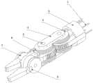
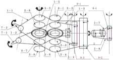
图1为本发明末端工具的整体结构示意图。Fig. 1 is a schematic diagram of the overall structure of the end tool of the present invention.
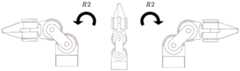
图2是图1所示的末端工具的俯仰运动动作图。FIG. 2 is an action diagram of a pitching motion of the end tool shown in FIG. 1 .
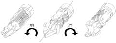
图3是图1所示的末端工具的偏航关节旋转动作图。Fig. 3 is a diagram showing a yaw joint rotation operation of the end tool shown in Fig. 1 .
图4是图1所示的末端工具的滚转运动动作图。FIG. 4 is an action diagram of the rolling movement of the end tool shown in FIG. 1 .
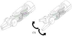
图5是图1所示的末端工具的末端夹持工具开合动作图。Fig. 5 is an opening and closing action diagram of the end holding tool of the end tool shown in Fig. 1 .
图6是本发明末端工具的传动原理图。Fig. 6 is a schematic diagram of the transmission principle of the end tool of the present invention.
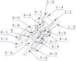
图7是本发明末端工具的俯仰运动相关结构示意图。Fig. 7 is a schematic diagram of the structure related to the pitching motion of the end tool of the present invention.
图8是图7所示的末端工具的结构分解示意图。FIG. 8 is an exploded schematic diagram of the structure of the end tool shown in FIG. 7 .
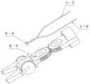
图9是本发明的末端工具的偏航运动相关结构示意图。Fig. 9 is a schematic diagram of the structure related to the yaw motion of the end tool of the present invention.
图10是图9所示的末端工具的结构分解示意图。FIG. 10 is an exploded schematic diagram of the structure of the end tool shown in FIG. 9 .
图11是图9所示的末端工具的结构侧视图。Fig. 11 is a side view of the structure of the tip tool shown in Fig. 9 .
其中,驱动绳1,第一驱动绳1-1,第二驱动绳1-2,第三驱动绳1-3,第四驱动绳组1-4,第五驱动绳1-5,第六驱动绳1-6,第七驱动绳1-7,第八驱动绳1-8;Among them, the
滚转基座2,第一圆柱凸台2-1,第二圆柱凸台2-2;Rolling
导向轮组3,第一导向轮3-1,第二导向轮3-2,第三导向轮3-3,第四导向轮3-4,第五导向轮3-5,第六导向轮3-6,第七导向轮3-7,第八导向轮3-8;
连杆4;connecting
轴销5,第一轴销5-1,第二轴销5-2,第三轴销5-3;
偏航关节6,第三圆柱凸台6-1,圆柱孔6-2,第四圆柱凸台6-3;Yaw joint 6, third cylindrical boss 6-1, cylindrical hole 6-2, fourth cylindrical boss 6-3;
末端夹持工具7,第一夹持钳7-1,第二夹持钳7-2;
固丝扣8,第一固丝扣8-1,第二固丝扣8-2,第三固丝扣8-3;
驱动电机9,第一电机9-1,第二电机9-2,第三电机9-3,第四电机9-4。Driving motor 9, first motor 9-1, second motor 9-2, third motor 9-3, fourth motor 9-4.
具体实施方式Detailed ways
以下通过附图和实施例对本发明的技术方案作进一步说明。The technical solutions of the present invention will be further described below through the accompanying drawings and embodiments.
结合图1至图11,本发明提供一种关节运动解耦的线驱动微创手术机器人末端工具,包括驱动绳1,滚转基座2,导向轮组3,连杆4,轴销5,偏航关节6,末端夹持工具7,固丝扣8和驱动电机9。1 to 11 , the present invention provides a wire-driven minimally invasive surgical robot terminal tool decoupling joint motion, including a driving
所述滚转基座2一端与驱动电机连接,另一端设置第一齿轮;所述偏航关节6一端设有与第一齿轮相啮合的第二齿轮,另一端设有连接板;所述连杆4的两端分别通过轴销与所述第一齿轮和所述第二齿轮转动连接;所述末端夹持工具7包括第一夹持钳7-1和第二夹持钳7-2,所述第一夹持钳7-1和第二夹持钳7-2通过第三轴销5-3对称的安装于所述连接板的两侧。工作过程中,偏航关节6与滚转基座2采用齿轮啮合连接,消除了各传动关节之间的运动耦合,保证可靠、高精度地进行驱动运动,减小了驱动控制复杂度。One end of the rolling
优选的,还包括第一驱动绳组、第二驱动绳组、第三驱动绳组和第四驱动绳组,驱动电机9包括第一电机9-1、第二电机9-2、第三电机9-3和第四电机9-4;所述第一驱动绳组由第二电机9-2驱动并带动第一夹持钳7-1围绕第三轴销5-3做俯仰运动,所述第二驱动绳组由第三电机9-3驱动并带动第二夹持钳7-2围绕第三轴销5-3做俯仰运动,所述第三驱动绳组由第四电机9-4驱动并带动偏航关节6围绕滚转基座2做旋转运动,所述第四驱动绳组由第一电机9-1驱动并带动末端工具整体做沿自身轴线的滚转运动。Preferably, it also includes a first drive rope set, a second drive rope set, a third drive rope set and a fourth drive rope set, and the drive motor 9 includes a first motor 9-1, a second motor 9-2, a third motor 9-3 and the fourth motor 9-4; the first driving rope group is driven by the second motor 9-2 and drives the first clamping pliers 7-1 to perform pitching motion around the third pin 5-3, the The second driving rope group is driven by the third motor 9-3 and drives the second clamping pliers 7-2 to perform pitching motion around the third shaft pin 5-3, and the third driving rope group is driven by the fourth motor 9-4 And drive the
即末端工具有4个自由度,分别是末端工具的俯仰自由度R1,末端工具的偏航自由度R2,末端工具的滚转自由度R3,末端工具的开合自由度C4;俯仰自由度R1提供末端工具的俯仰运动,偏航自由度R2提供末端工具的偏航运动,俯仰自由度R1轴线垂直于偏航自由度R2轴线;末端夹持工具7的滚转自由度R3轴线同时垂直于末端工具的俯仰自由度R1和偏航自由度R2轴线,提供末端工具的滚转运动;末端夹持工具7的开合自由度C4提供末端工具的打开与闭合。That is, the end tool has 4 degrees of freedom, namely the pitching degree of freedom R1 of the end tool, the yaw degree of freedom R2 of the end tool, the rolling degree of freedom R3 of the end tool, the opening and closing degree of freedom C4 of the end tool; the pitching degree of freedom R1 The pitch motion of the end tool is provided, and the yaw degree of freedom R2 provides the yaw motion of the end tool. The axis of the pitch degree of freedom R1 is perpendicular to the axis of the yaw degree of freedom R2; the axis of the roll degree of freedom R3 of the
优选的,所述第一齿轮的两侧分别同轴设置第一圆柱凸台2-1和第二圆柱凸台2-2,所述第二齿轮的两侧分别同轴设置第三圆柱凸台6-1和第四圆柱凸台6-3,所述第一圆柱凸台2-1、第二圆柱凸台2-2、第三圆柱凸台6-1和第四圆柱凸台6-3的外侧均同轴安装有设置整圈丝槽的导向轮。Preferably, a first cylindrical boss 2-1 and a second cylindrical boss 2-2 are coaxially arranged on both sides of the first gear, and a third cylindrical boss is arranged coaxially on both sides of the second gear 6-1 and the fourth cylindrical boss 6-3, the first cylindrical boss 2-1, the second cylindrical boss 2-2, the third cylindrical boss 6-1 and the fourth cylindrical boss 6-3 The outer sides of the guide wheels are coaxially equipped with a full circle of wire grooves.
本实施例中,所述导向轮包括第一导向轮3-1、第二导向轮3-2、第三导向轮3-3、第四导向轮3-4、第五导向轮3-5、第六导向轮3-6、第七导向轮3-7和第八导向轮3-8,所述第二导向轮3-2和第一导向轮3-1依次设置于所述第一圆柱凸台2-1的外侧,所述第三导向轮3-3和第四导向轮3-4依次设置于所述第二圆柱凸台2-2的外侧,所述第六导向轮3-6和第五导向轮3-5依次设置于所述第三圆柱凸台6-1的外侧,所述第七导向轮3-7和第八导向轮3-8依次设置于所述第四圆柱凸台6-3的外侧。In this embodiment, the guide wheels include a first guide wheel 3-1, a second guide wheel 3-2, a third guide wheel 3-3, a fourth guide wheel 3-4, a fifth guide wheel 3-5, The sixth guide wheel 3-6, the seventh guide wheel 3-7 and the eighth guide wheel 3-8, the second guide wheel 3-2 and the first guide wheel 3-1 are arranged on the first cylindrical convex The outer side of the platform 2-1, the third guide wheel 3-3 and the fourth guide wheel 3-4 are sequentially arranged on the outer side of the second cylindrical boss 2-2, the sixth guide wheel 3-6 and The fifth guide wheel 3-5 is sequentially arranged on the outside of the third cylindrical boss 6-1, and the seventh guide wheel 3-7 and the eighth guide wheel 3-8 are arranged sequentially on the fourth cylindrical boss 6-3 outside.
优选的,所述第一驱动绳组包括:Preferably, the first drive rope set includes:
第一驱动绳1-1,所述第一驱动绳1-1的一端缠绕于第二电机9-2的输出轴上,另一端依次绕过第一导向轮3-1的丝槽、第五导向轮3-5的丝槽和第二夹持钳7-2的丝槽上侧并固定连接于第二固丝扣8-2上;The first driving rope 1-1, one end of the first driving rope 1-1 is wound on the output shaft of the second motor 9-2, and the other end goes around the silk groove of the first guide wheel 3-1, the fifth The wire groove of the guide wheel 3-5 and the upper side of the wire groove of the second clamping pliers 7-2 are fixedly connected to the second fixed thread buckle 8-2;
第二驱动绳1-2,所述第二驱动绳1-2的一端缠绕于第二电机9-2的输出轴上,另一端依次绕过第四导向轮3-4的丝槽、第八导向轮3-8的丝槽和第二夹持钳7-2的丝槽下侧并固定连接于第二固丝扣8-2上;The second driving rope 1-2, one end of the second driving rope 1-2 is wound on the output shaft of the second motor 9-2, and the other end goes around the silk groove of the fourth guide wheel 3-4, the eighth The wire groove of the guide wheel 3-8 and the lower side of the wire groove of the second clamping pliers 7-2 are fixedly connected to the second fixed thread buckle 8-2;
所述第一驱动绳1-1和第二驱动绳1-2在第二电机9-2轴的输出轴上的缠绕方向相反,所述第二固丝扣8-2固定设置于所述第二夹持钳7-2上,所述第一驱动绳1-1和第二驱动绳1-2分别位于所述第二固丝扣8-2相对的两端。The winding directions of the first driving rope 1-1 and the second driving rope 1-2 on the output shaft of the second motor 9-2 are opposite, and the second fixed thread buckle 8-2 is fixedly arranged on the second motor 9-2. On the two clamping pliers 7-2, the first driving rope 1-1 and the second driving rope 1-2 are respectively located at opposite ends of the second fastening thread buckle 8-2.
优选的,所述第二驱动绳组包括:Preferably, the second drive rope set includes:
第三驱动绳1-3,所述第三驱动绳1-3的一端缠绕于第三电机9-3的输出轴上,另一端依次绕过第二导向轮3-2的丝槽、第六导向轮3-6的丝槽和第一夹持钳7-1的丝槽上侧并固定连接于第一固丝扣8-1上;The third driving rope 1-3, one end of the third driving rope 1-3 is wound on the output shaft of the third motor 9-3, and the other end goes around the silk groove of the second guide wheel 3-2, the sixth The wire groove of the guide wheel 3-6 and the upper side of the wire groove of the first clamping pliers 7-1 are fixedly connected to the first fixed thread buckle 8-1;
第四驱动绳1-4,所述第四驱动绳1-4的一端缠绕于第三电机9-3的输出轴上,另一端依次绕过第三导向轮3-3的丝槽、第七导向轮3-7的丝槽和第一夹持钳7-1的丝槽下侧并固定连接于第一固丝扣8-1上;The fourth driving rope 1-4, one end of the fourth driving rope 1-4 is wound on the output shaft of the third motor 9-3, and the other end goes around the silk groove of the third guide wheel 3-3 successively, the seventh The wire groove of the guide wheel 3-7 and the lower side of the wire groove of the first clamping pliers 7-1 are fixedly connected to the first fixed thread buckle 8-1;
所述第三驱动绳1-3和第四驱动绳1-4在第二电机9-2轴的输出轴上的缠绕方向相反,所述第一固丝扣8-1固定设置于所述第一夹持钳7-1上,所述第三驱动绳1-3和第四驱动绳1-4分别位于所述第一固丝扣8-1相对的两端。The winding directions of the third drive rope 1-3 and the fourth drive rope 1-4 on the output shaft of the second motor 9-2 are opposite, and the first fixed thread buckle 8-1 is fixedly arranged on the second motor 9-2. On a clamping pliers 7-1, the third driving rope 1-3 and the fourth driving rope 1-4 are respectively located at opposite ends of the first fastening thread 8-1.
优选的,所述第三驱动绳组包括:Preferably, the third drive rope set includes:
第五驱动绳1-5,所述第五驱动绳1-5的一端缠绕于第一电机9-1的输出轴上,另一端依次绕过第一圆柱凸台2-1和第三圆柱凸台6-1并固定连接于第三固丝扣8-3上;The fifth driving rope 1-5, one end of the fifth driving rope 1-5 is wound on the output shaft of the first motor 9-1, and the other end is wound around the first cylindrical boss 2-1 and the third cylindrical boss in turn. The platform 6-1 is fixedly connected to the third fastening thread 8-3;
第六驱动绳1-6,所述第六驱动绳1-6的一端缠绕于第一电机9-1的输出轴上,另一端依次绕过第二圆柱凸台2-2和第四圆柱凸台6-3并固定连接于第三固丝扣8-3上;The sixth driving rope 1-6, one end of the sixth driving rope 1-6 is wound on the output shaft of the first motor 9-1, and the other end is wound around the second cylindrical boss 2-2 and the fourth cylindrical boss in turn. The platform 6-3 is fixedly connected to the third fastening thread 8-3;
所述第五驱动绳1-5和第六驱动绳1-6在第一电机9-1轴的输出轴上的缠绕方向相反,所述第三固丝扣8-3固定设置于所述第二齿轮的圆柱孔6-2内,所述第五驱动绳1-5和第六驱动绳1-6分别位于所述第三固丝扣8-3相对的两端。The winding directions of the fifth driving rope 1-5 and the sixth driving rope 1-6 on the output shaft of the first motor 9-1 are opposite, and the third fastening thread 8-3 is fixedly arranged on the first motor 9-1. In the cylindrical hole 6-2 of the second gear, the fifth driving rope 1-5 and the sixth driving rope 1-6 are respectively located at opposite ends of the third fixed threaded buckle 8-3.
优选的,所述第三驱动绳组包括第七驱动绳1-7和第八驱动绳1-8,所述第七驱动绳1-7和第八驱动绳1-8的一端反向缠绕于所述滚转基座2靠近第四电机9-4的一端,所述第七驱动绳1-7和第八驱动绳1-8的另一端反向缠绕于所述第四电机9-4轴的输出轴上。Preferably, the third driving rope set includes a seventh driving rope 1-7 and an eighth driving rope 1-8, and one end of the seventh driving rope 1-7 and the eighth driving rope 1-8 is reversely wound on The rolling
本实施例中,所述连杆4的一端通过第一轴销5-1与所述第一齿轮连接,所述连杆4的另一端通过第二轴销5-2与所述第二齿轮连接。所述第一导向轮3-1、第二导向轮3-2、第三导向轮3-3和第四导向轮3-4均套设于所述第一轴销5-1上,第五导向轮3-5、第六导向轮3-6、第七导向轮3-7和第八导向轮3-8均套设于所述第二轴销5-2上。In this embodiment, one end of the connecting
如图7至8所示:本发明的线驱动微创手术机器人末端工具的俯仰运动和夹持动作由第一夹持钳7-1,第二夹持钳7-2,偏航关节6,第一驱动绳1-1,第二驱动绳1-2,第三驱动绳1-3,第四驱动绳1-4实现,偏航关节6通过连杆4与滚转基座2连接,使用齿轮啮合传动,滚转基座2上布置了第一轴销5-1,第一轴销5-1上安装了第一导向轮3-1,第二导向轮3-2,第三导向轮3-3,第四导向轮3-4作为驱动绳传动系统的驱动绳导向元件;偏航关节6上布置了第二轴销5-2,第二轴销5-2上转动地安装有第五导向轮3-5,第六导向轮3-6,第七导向轮3-7,第八导向轮3-8作为驱动绳传动系统的驱动绳导向元件。As shown in Figures 7 to 8: the pitching motion and clamping action of the end tool of the wire-driven minimally invasive surgery robot of the present invention is composed of the first clamping forceps 7-1, the second clamping forceps 7-2, the
如图6的所示,本发明的工作原理如下:As shown in Figure 6, the working principle of the present invention is as follows:
第一夹持钳7-1和第二夹持钳7-2在第一驱动绳1-1、第二驱动绳1-2、第三驱动绳1-3和第四驱动绳1-4的牵引下能够围绕第三轴销5-3做俯仰运动;即第二电机轴转动地带动第一驱动绳1-1和第二驱动绳1-2牵拉运动的时候能够带动第二夹持钳7-2围绕第三轴销5-3做俯仰运动,第三电机轴转动地带动第三驱动绳1-3和第四驱动绳1-4做牵拉运动的时候能够带动第一夹持钳7-1围绕第三轴销5-3做俯仰运动;The first clamping pliers 7-1 and the second clamping pliers 7-2 are on the first driving rope 1-1, the second driving rope 1-2, the third driving rope 1-3 and the fourth driving rope 1-4. Under traction, pitching motion can be performed around the third shaft pin 5-3; that is, the second motor shaft can drive the second clamping pliers when the first drive rope 1-1 and the second drive rope 1-2 are pulled and moved. 7-2 Do pitching motion around the third shaft pin 5-3, the third motor shaft rotates to drive the third driving rope 1-3 and the fourth driving rope 1-4 to drive the first clamping pliers when doing pulling motion 7-1 makes a pitching motion around the third pivot pin 5-3;
当第二电机轴和第三电机轴同向转动时,第一夹持钳7-1和第二夹持钳7-2围绕第三轴销5-3同向转动,继而带动末端夹持工具做俯仰运动,完成末端工具的俯仰自由度R1;当第二电机轴和第三电机轴反向转动时,第一夹持钳7-1和第二夹持钳7-2围绕第三轴销5-3反向转动,继而带动末端夹持工具做开合运动,完成末端工具的开合自由度C4;When the second motor shaft and the third motor shaft rotate in the same direction, the first clamping pliers 7-1 and the second clamping pliers 7-2 rotate in the same direction around the third shaft pin 5-3, and then drive the end clamping tool Perform pitching motion to complete the pitching degree of freedom R1 of the end tool; when the second motor shaft and the third motor shaft rotate in the opposite direction, the first clamping pliers 7-1 and the second clamping pliers 7-2 surround the third shaft pin 5-3 Reverse rotation, and then drive the end clamping tool to do the opening and closing movement, and complete the opening and closing freedom C4 of the end tool;
第一电机轴转动地带动第五驱动绳1-5和第六驱动绳1-6做牵拉运动时能够带动偏航关节6围绕滚转基座2做行星齿轮式的旋转运动,实现末端工具的偏航自由度R2;When the first motor shaft rotates to drive the fifth driving rope 1-5 and the sixth driving rope 1-6 to do pulling motion, it can drive the
第四电机轴转动时即可带动末端工具整体做轴线垂直于俯仰运动转动轴线和偏航运动转动轴线的滚转运动,完成末端工具的滚转自由度R3。When the fourth motor shaft rotates, it can drive the end tool as a whole to perform a rolling motion whose axis is perpendicular to the rotation axis of the pitch motion and the rotation axis of the yaw motion, thereby completing the rolling degree of freedom R3 of the end tool.
以上所述,仅是本发明较佳实施例而已,并非对本发明的技术范围作任何限制,故凡是依据本发明的技术实质对以上实施例所作的任何细微修改、等同变化与修饰,均仍属于本发明技术方案的范围。The above are only preferred embodiments of the present invention, and do not limit the technical scope of the present invention in any way, so any minor modifications, equivalent changes and modifications made to the above embodiments according to the technical essence of the present invention still belong to The scope of the technical solution of the present invention.
Claims (10)
Priority Applications (1)
| Application Number | Priority Date | Filing Date | Title |
|---|---|---|---|
| CN202310253049.7ACN116370085A (en) | 2023-03-14 | 2023-03-14 | A wire-driven minimally invasive surgical robot end tool with joint motion decoupling |
Applications Claiming Priority (1)
| Application Number | Priority Date | Filing Date | Title |
|---|---|---|---|
| CN202310253049.7ACN116370085A (en) | 2023-03-14 | 2023-03-14 | A wire-driven minimally invasive surgical robot end tool with joint motion decoupling |
Publications (1)
| Publication Number | Publication Date |
|---|---|
| CN116370085Atrue CN116370085A (en) | 2023-07-04 |
Family
ID=86972296
Family Applications (1)
| Application Number | Title | Priority Date | Filing Date |
|---|---|---|---|
| CN202310253049.7APendingCN116370085A (en) | 2023-03-14 | 2023-03-14 | A wire-driven minimally invasive surgical robot end tool with joint motion decoupling |
Country Status (1)
| Country | Link |
|---|---|
| CN (1) | CN116370085A (en) |
Cited By (1)
| Publication number | Priority date | Publication date | Assignee | Title |
|---|---|---|---|---|
| CN118177917A (en)* | 2024-03-22 | 2024-06-14 | 邦士医疗科技股份有限公司 | Multi-degree-of-freedom surgical forceps with replaceable forceps heads |
Citations (5)
| Publication number | Priority date | Publication date | Assignee | Title |
|---|---|---|---|---|
| CN101637402A (en)* | 2009-10-23 | 2010-02-03 | 天津大学 | Minimally invasive surgical wire driving and four-freedom surgical tool |
| CN206603817U (en)* | 2016-12-12 | 2017-11-03 | 哈工大机器人集团有限公司 | Knee joint micro-wound operation robot |
| CN112043389A (en)* | 2020-09-30 | 2020-12-08 | 深圳市精锋医疗科技有限公司 | Surgical instrument, slave operation device, and surgical robot |
| CN212996717U (en)* | 2020-09-30 | 2021-04-20 | 深圳市精锋医疗科技有限公司 | Surgical instrument, slave operation device, and surgical robot |
| CN115645057A (en)* | 2022-10-20 | 2023-01-31 | 上海工程技术大学 | Four-degree-of-freedom gripper for minimally invasive surgery |
- 2023
- 2023-03-14CNCN202310253049.7Apatent/CN116370085A/enactivePending
Patent Citations (5)
| Publication number | Priority date | Publication date | Assignee | Title |
|---|---|---|---|---|
| CN101637402A (en)* | 2009-10-23 | 2010-02-03 | 天津大学 | Minimally invasive surgical wire driving and four-freedom surgical tool |
| CN206603817U (en)* | 2016-12-12 | 2017-11-03 | 哈工大机器人集团有限公司 | Knee joint micro-wound operation robot |
| CN112043389A (en)* | 2020-09-30 | 2020-12-08 | 深圳市精锋医疗科技有限公司 | Surgical instrument, slave operation device, and surgical robot |
| CN212996717U (en)* | 2020-09-30 | 2021-04-20 | 深圳市精锋医疗科技有限公司 | Surgical instrument, slave operation device, and surgical robot |
| CN115645057A (en)* | 2022-10-20 | 2023-01-31 | 上海工程技术大学 | Four-degree-of-freedom gripper for minimally invasive surgery |
Cited By (2)
| Publication number | Priority date | Publication date | Assignee | Title |
|---|---|---|---|---|
| CN118177917A (en)* | 2024-03-22 | 2024-06-14 | 邦士医疗科技股份有限公司 | Multi-degree-of-freedom surgical forceps with replaceable forceps heads |
| CN118177917B (en)* | 2024-03-22 | 2025-01-28 | 邦士医疗科技股份有限公司 | Multi-degree-of-freedom surgical forceps with replaceable forceps heads |
Similar Documents
| Publication | Publication Date | Title |
|---|---|---|
| US11076922B2 (en) | Mechanical manipulator for surgical instruments | |
| CN104066399B (en) | differential component | |
| EP3556520B1 (en) | Remote-center-of-motion mechanism | |
| CN101889900B (en) | Master-slave integrated mechanical arm for assisting minimally invasive surgery | |
| US10220522B2 (en) | Gear train assemblies for robotic surgical systems | |
| WO2021184791A1 (en) | Serpentine surgical robot applied to minimally invasive surgery | |
| CN104799891A (en) | Instrument for robot-assisted micro-invasive surgery | |
| WO2017063472A1 (en) | Minimally invasive surgery instrument having self-rotating terminal and instrument terminal thereof | |
| CN107550541B (en) | A handheld flexible multi-joint surgical instrument for minimally invasive abdominal surgery | |
| US12402960B2 (en) | Mechanical manipulator for surgical instruments | |
| CN102525658B (en) | Manual three-degree-of-freedom micro manipulator for minimally invasive surgery | |
| CN104116547A (en) | Low-friction low-inertia surgical instrument for minimally invasive surgical robot | |
| CN104758012B (en) | Tail end instrument for single port laparoscopy minimally invasive surgery flexible robot with multiple freedom degrees | |
| WO2022249524A1 (en) | Arm device | |
| CN105455902A (en) | Wrist of robot and surgical robot | |
| CN212853621U (en) | Surgical instrument, slave operation device, and surgical robot | |
| CN113100949B (en) | Front end execution device for surgical robot | |
| CN116370085A (en) | A wire-driven minimally invasive surgical robot end tool with joint motion decoupling | |
| CN115633997A (en) | A minimally invasive surgical instrument capable of automatic opening, closing and rotation | |
| CN115645057A (en) | Four-degree-of-freedom gripper for minimally invasive surgery | |
| CN113208736A (en) | Instrument driving device, instrument tail end assembly, surgical instrument and surgical robot | |
| CN113662673A (en) | Mechanical arm, slave operation equipment and surgical robot | |
| CN108433811A (en) | A kind of integral layout structure of the single hole operating robot with rotation positioning joint | |
| CN113100948B (en) | Front end execution device for surgical robot | |
| WO2025139284A1 (en) | Rolling kinematic pair-fronted snake-shaped end-effector mechanism |
Legal Events
| Date | Code | Title | Description |
|---|---|---|---|
| PB01 | Publication | ||
| PB01 | Publication | ||
| SE01 | Entry into force of request for substantive examination | ||
| SE01 | Entry into force of request for substantive examination |