CN116360135A - Peep-proof structure and electronic display device - Google Patents
Peep-proof structure and electronic display deviceDownload PDFInfo
- Publication number
- CN116360135A CN116360135ACN202310591219.2ACN202310591219ACN116360135ACN 116360135 ACN116360135 ACN 116360135ACN 202310591219 ACN202310591219 ACN 202310591219ACN 116360135 ACN116360135 ACN 116360135A
- Authority
- CN
- China
- Prior art keywords
- peeping
- unit
- peep
- units
- proof
- Prior art date
- Legal status (The legal status is an assumption and is not a legal conclusion. Google has not performed a legal analysis and makes no representation as to the accuracy of the status listed.)
- Granted
Links
- 208000008918voyeurismDiseases0.000claimsdescription239
- 239000011248coating agentSubstances0.000claimsdescription27
- 238000000576coating methodMethods0.000claimsdescription27
- 230000005684electric fieldEffects0.000claimsdescription26
- 238000009792diffusion processMethods0.000claimsdescription15
- 239000010408filmSubstances0.000description36
- 230000000694effectsEffects0.000description14
- 229920000139polyethylene terephthalatePolymers0.000description5
- 239000005020polyethylene terephthalateSubstances0.000description5
- 239000000463materialSubstances0.000description4
- 239000002245particleSubstances0.000description4
- 230000009286beneficial effectEffects0.000description3
- 239000010410layerSubstances0.000description3
- 239000012788optical filmSubstances0.000description3
- 244000144985peepSpecies0.000description3
- 239000004417polycarbonateSubstances0.000description3
- 239000012790adhesive layerSubstances0.000description2
- 239000010405anode materialSubstances0.000description2
- 239000004020conductorSubstances0.000description2
- 238000010586diagramMethods0.000description2
- 239000006185dispersionSubstances0.000description2
- 239000006260foamSubstances0.000description2
- 239000003292glueSubstances0.000description2
- 230000003287optical effectEffects0.000description2
- 229920000515polycarbonatePolymers0.000description2
- 230000015572biosynthetic processEffects0.000description1
- 239000007772electrode materialSubstances0.000description1
- 239000011521glassSubstances0.000description1
- 238000009434installationMethods0.000description1
- 239000011159matrix materialSubstances0.000description1
- 238000000034methodMethods0.000description1
- 238000012986modificationMethods0.000description1
- 230000004048modificationEffects0.000description1
- 239000007773negative electrode materialSubstances0.000description1
- -1polyethylene terephthalatePolymers0.000description1
- 239000007774positive electrode materialSubstances0.000description1
- 230000002265preventionEffects0.000description1
- 239000000126substanceSubstances0.000description1
Images


Classifications
- G—PHYSICS
- G02—OPTICS
- G02F—OPTICAL DEVICES OR ARRANGEMENTS FOR THE CONTROL OF LIGHT BY MODIFICATION OF THE OPTICAL PROPERTIES OF THE MEDIA OF THE ELEMENTS INVOLVED THEREIN; NON-LINEAR OPTICS; FREQUENCY-CHANGING OF LIGHT; OPTICAL LOGIC ELEMENTS; OPTICAL ANALOGUE/DIGITAL CONVERTERS
- G02F1/00—Devices or arrangements for the control of the intensity, colour, phase, polarisation or direction of light arriving from an independent light source, e.g. switching, gating or modulating; Non-linear optics
- G02F1/01—Devices or arrangements for the control of the intensity, colour, phase, polarisation or direction of light arriving from an independent light source, e.g. switching, gating or modulating; Non-linear optics for the control of the intensity, phase, polarisation or colour
- G02F1/13—Devices or arrangements for the control of the intensity, colour, phase, polarisation or direction of light arriving from an independent light source, e.g. switching, gating or modulating; Non-linear optics for the control of the intensity, phase, polarisation or colour based on liquid crystals, e.g. single liquid crystal display cells
- G02F1/1323—Arrangements for providing a switchable viewing angle
- G—PHYSICS
- G02—OPTICS
- G02B—OPTICAL ELEMENTS, SYSTEMS OR APPARATUS
- G02B26/00—Optical devices or arrangements for the control of light using movable or deformable optical elements
- G02B26/001—Optical devices or arrangements for the control of light using movable or deformable optical elements based on interference in an adjustable optical cavity
- G—PHYSICS
- G02—OPTICS
- G02B—OPTICAL ELEMENTS, SYSTEMS OR APPARATUS
- G02B6/00—Light guides; Structural details of arrangements comprising light guides and other optical elements, e.g. couplings
- G02B6/0001—Light guides; Structural details of arrangements comprising light guides and other optical elements, e.g. couplings specially adapted for lighting devices or systems
- G02B6/0011—Light guides; Structural details of arrangements comprising light guides and other optical elements, e.g. couplings specially adapted for lighting devices or systems the light guides being planar or of plate-like form
- G02B6/0033—Means for improving the coupling-out of light from the light guide
- G02B6/005—Means for improving the coupling-out of light from the light guide provided by one optical element, or plurality thereof, placed on the light output side of the light guide
- G02B6/0051—Diffusing sheet or layer
- G—PHYSICS
- G09—EDUCATION; CRYPTOGRAPHY; DISPLAY; ADVERTISING; SEALS
- G09F—DISPLAYING; ADVERTISING; SIGNS; LABELS OR NAME-PLATES; SEALS
- G09F9/00—Indicating arrangements for variable information in which the information is built-up on a support by selection or combination of individual elements
- G09F9/30—Indicating arrangements for variable information in which the information is built-up on a support by selection or combination of individual elements in which the desired character or characters are formed by combining individual elements
Landscapes
- Physics & Mathematics (AREA)
- General Physics & Mathematics (AREA)
- Optics & Photonics (AREA)
- Spectroscopy & Molecular Physics (AREA)
- Nonlinear Science (AREA)
- Engineering & Computer Science (AREA)
- Theoretical Computer Science (AREA)
- Chemical & Material Sciences (AREA)
- Crystallography & Structural Chemistry (AREA)
- Devices For Indicating Variable Information By Combining Individual Elements (AREA)
Abstract
Description
Translated fromChinese技术领域technical field
本申请属于显示技术领域,更具体地说,是涉及一种防窥结构及电子显示设备。The present application belongs to the field of display technology, and more specifically relates to an anti-peeping structure and an electronic display device.
背景技术Background technique
随着可携带显示装备的普及,电子显示设备的防窥视技术也日益受到重视,人们希望在公共场合使用电子显示设备的时候可以保护个人的隐私。With the popularization of portable display equipment, the anti-peeping technology of electronic display equipment is also increasingly valued, and people hope that personal privacy can be protected when electronic display equipment is used in public places.
目前,带有防窥模式的电子显示设备,防窥结构一般设置在电子显示设备内,当需要防窥时,可以设置为防窥模式,但是当不需要防窥时却无法进行调控以将防窥模式灵活切换为非防窥模式,导致使用起来很不方便。At present, for electronic display devices with anti-peeping mode, the anti-peeping structure is generally set in the electronic display device. The peeping mode can be flexibly switched to non-peeping mode, which makes it very inconvenient to use.
发明内容Contents of the invention
本申请实施例的目的在于提供一种防窥结构及电子显示设备,以解决现有技术中存在的电子显示设备无法在防窥模式和非防窥模式之间灵活切换的技术问题。The purpose of the embodiments of the present application is to provide an anti-peeping structure and an electronic display device to solve the technical problem in the prior art that the electronic display device cannot flexibly switch between the anti-peeping mode and the non-peeping-proof mode.
为实现上述目的,本申请采用的技术方案是:提供一种防窥结构,包括壳体、多个防窥单元及驱动结构;所述壳体为具有空腔的透光结构,各所述防窥结构分别间隔设于所述壳体的空腔中;所述防窥单元具有相对设置的第一侧和第二侧,当所述第一侧朝向光源时,所述防窥单元处于防窥模式;当所述第二侧朝向光源时,所述防窥单元处于非防窥模式;所述驱动结构用于驱动各所述防窥单元在所述空腔中转动以使得各所述防窥单元在所述防窥模式和所述非防窥模式之间相互切换。In order to achieve the above purpose, the technical solution adopted by this application is: provide an anti-peeping structure, including a casing, a plurality of anti-peeping units and a driving structure; the casing is a light-transmitting structure with a cavity, and each of the anti-peeping The peeping structures are respectively arranged at intervals in the cavity of the housing; the anti-peeping unit has a first side and a second side oppositely arranged, and when the first side faces the light source, the peeping-proof unit is in the anti-peeping position mode; when the second side faces the light source, the anti-peeping unit is in a non-peeping-proof mode; the driving structure is used to drive each of the anti-peeping units to rotate in the cavity so that each of the anti-peeping The unit is mutually switchable between the peep-proof mode and the non-peep-proof mode.
在一种可能的设计中,所述驱动结构还用于驱动所述防窥单元旋转以使得所述防窥单元停留在不同的防窥角度位置。In a possible design, the driving structure is also used to drive the anti-peeping unit to rotate so that the anti-peeping unit stays at different anti-peeping angle positions.
在一种可能的设计中,所述防窥结构包括多个驱动结构,每个驱动结构用于驱动一个所述防窥单元旋转或者用于驱动多个连续分布的所述防窥单元旋转。In a possible design, the anti-peeping structure includes a plurality of driving structures, and each driving structure is used to drive one anti-peeping unit to rotate or to drive a plurality of continuously distributed anti-peeping units to rotate.
在一种可能的设计中,所述驱动结构包括多个电场单元,所述电场单元设于所述壳体上并在所述空腔中形成电场,所述电场单元作用在所述防窥单元上以驱动所述防窥单元旋转。In a possible design, the drive structure includes a plurality of electric field units, the electric field units are arranged on the housing and form an electric field in the cavity, and the electric field units act on the anti-peeping unit to drive the anti-peeping unit to rotate.
在一种可能的设计中,所述防窥单元上设有正极涂层和负极涂层,所述正极涂层和所述负极涂层分布设于所述第一侧和所述第二侧,且所述正极涂层和所述负极涂层分别对称设于所述防窥单元的旋转轴线的两侧。In a possible design, the anti-peeping unit is provided with a positive electrode coating and a negative electrode coating, and the positive electrode coating and the negative electrode coating are distributed on the first side and the second side, In addition, the positive electrode coating and the negative electrode coating are symmetrically arranged on both sides of the rotation axis of the anti-peeping unit.
在一种可能的设计中,所述驱动结构包括多个旋转驱动件,各所述旋转驱动件与各所述防窥单元连接并用于驱动各所述防窥单元旋转。In a possible design, the driving structure includes a plurality of rotating driving parts, each of which is connected to each of the anti-peeping units and used to drive each of the anti-peeping units to rotate.
在一种可能的设计中,所述空腔中设有多根依次间隔分布的轴杆,每个所述轴杆上分布有多个所述防窥单元,各所述防窥单元分别转动设于所述轴杆上。In a possible design, the cavity is provided with a plurality of shafts distributed in sequence at intervals, and each of the shafts is distributed with a plurality of the anti-peeping units, and each of the anti-peeping units is respectively rotated to on the shaft.
在一种可能的设计中,所述防窥单元包括防窥膜和扩散膜,所述扩散膜贴设于所述防窥膜的一侧,所述防窥膜将光线的可视角控制在预设范围内,所述扩散膜用于将射入其中的光线进行发散。In a possible design, the anti-peeping unit includes an anti-peeping film and a diffusion film, the diffusion film is attached to one side of the anti-peeping film, and the anti-peeping film controls the visible angle of light to a predetermined Within a certain range, the diffusion film is used to diverge the light incident therein.
本申请提供的防窥结构的有益效果在于:本申请实施例中提供的防窥结构,通过将防窥单元设于壳体内,并通过驱动结构来驱动防窥单元旋转,以使得防窥单元能够在防窥模式和非防窥模式之间灵活切换,方便用户根据实际需求进行使用。同时,通过将防窥结构分成多个防窥单元,使得防窥单元的长宽尺寸大大减少,从而便于防窥单元在有限厚度的空腔中进行翻边旋转,以满足防窥单元在防窥模式和非防窥模式之间灵活切换的要求,进而也使得防窥结构在能够灵活切换防窥模式和非防窥模式的前提下具有足够小的厚度。The beneficial effects of the anti-peeping structure provided by the present application are: the anti-peeping structure provided in the embodiment of the application, by setting the anti-peeping unit in the casing, and driving the anti-peeping unit to rotate through the driving structure, so that the anti-peeping unit can Flexible switching between anti-peep mode and non-peep-proof mode, convenient for users to use according to actual needs. At the same time, by dividing the anti-peeping structure into multiple anti-peeping units, the length and width of the anti-peeping unit are greatly reduced, so that the anti-peeping unit can be turned over in a cavity with a limited thickness to meet the needs of the anti-peeping unit. The requirement for flexible switching between the anti-peeping mode and the non-peepproof mode further makes the anti-peeping structure have a sufficiently small thickness on the premise of being able to flexibly switch between the anti-peeping mode and the non-peepproof mode.
另一方面,本申请还提供了一种电子显示设备,包括上述防窥结构。On the other hand, the present application also provides an electronic display device, including the above-mentioned anti-peeping structure.
在一种可能的设计中,所述电子显示设备还包括背光光源及显示模组,所述防窥结构设于所述背光光源与所述显示模组之间。In a possible design, the electronic display device further includes a backlight source and a display module, and the anti-peeping structure is arranged between the backlight source and the display module.
本申请提供的电子显示设备的有益效果在于:本申请实施例中提供的电子显示设备,通过上述防窥结构的设计,使得该电子显示设备能够在防窥模式和非防窥模式之间灵活切换,且在保证防窥功能的前提下实现超薄设计。The beneficial effect of the electronic display device provided by the present application is that: the electronic display device provided in the embodiment of the present application, through the design of the above-mentioned anti-peeping structure, enables the electronic display device to be flexibly switched between the anti-peeping mode and the non-peeping-proof mode , and realize the ultra-thin design under the premise of ensuring the anti-peeping function.
附图说明Description of drawings
为了更清楚地说明本申请实施例中的技术方案,下面将对实施例或现有技术描述中所需要使用的附图作简单地介绍,显而易见地,下面描述中的附图仅仅是本申请的一些实施例,对于本领域普通技术人员来讲,在不付出创造性劳动性的前提下,还可以根据这些附图获得其他的附图。In order to more clearly illustrate the technical solutions in the embodiments of the present application, the accompanying drawings that need to be used in the descriptions of the embodiments or the prior art will be briefly introduced below. Obviously, the accompanying drawings in the following description are only for the present application For some embodiments, those of ordinary skill in the art can also obtain other drawings based on these drawings without paying creative efforts.
图1为本申请实施例中提供的防窥结构的纵向剖视示意图;FIG. 1 is a schematic longitudinal sectional view of an anti-peeping structure provided in an embodiment of the present application;
图2为本申请实施例中提供的各防窥单元及各轴杆的局部分布示意图;Fig. 2 is a schematic diagram of the local distribution of each anti-peeping unit and each shaft provided in the embodiment of the present application;
图3为图1中防窥单元的结构示意图;Fig. 3 is a structural schematic diagram of the anti-peeping unit in Fig. 1;
图4为图3中防窥膜的结构示意图;Fig. 4 is a schematic structural view of the anti-peeping film in Fig. 3;
图5为本申请实施例中提供的电子显示设备的剖视示意图。FIG. 5 is a schematic cross-sectional view of an electronic display device provided in an embodiment of the present application.
其中,图中各附图标记:Wherein, each reference sign in the figure:
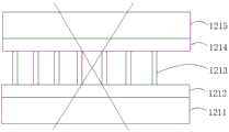
1、防窥结构;11、壳体;110、空腔;12、防窥单元;121、防窥膜;1211、PET层;1212、胶粘层;1213、细百叶窗膜纸;1214、PC层;1215、防炫硬涂层;122、扩散膜;1221、基材;1222、散色粒子;123、第一侧;124、第二侧;13、驱动结构;131、电场单元;132、正极涂层;133、负极涂层;14、轴杆;2、背光光源;21、反射膜;22、光源板;23、光学膜片;3、显示模组;4、外壳;5、泡棉胶。1. Anti-peeping structure; 11. Housing; 110. Cavity; 12. Anti-peeping unit; 121. Anti-peeping film; 1211. PET layer; 1212. Adhesive layer; ; 1215, anti-glare hard coating; 122, diffusion film; 1221, base material; 1222, scattering particles; 123, first side; 124, second side; 13, driving structure; Coating; 133. Negative electrode coating; 14. Shaft; 2. Backlight light source; 21. Reflective film; 22. Light source plate; 23. Optical diaphragm; 3. Display module; 4. Shell; 5. Foam glue .
具体实施方式Detailed ways
为了使本申请所要解决的技术问题、技术方案及有益效果更加清楚明白,以下结合附图及实施例,对本申请进行进一步详细说明。应当理解,此处所描述的具体实施例仅仅用以解释本申请,并不用于限定本申请。In order to make the technical problems, technical solutions and beneficial effects to be solved by the present application clearer, the present application will be further described in detail below in conjunction with the accompanying drawings and embodiments. It should be understood that the specific embodiments described here are only used to explain the present application, and are not intended to limit the present application.
需要说明的是,当元件被称为“固定于”或“设置于”另一个元件,它可以直接在另一个元件上或者间接在该另一个元件上。当一个元件被称为是“连接于”另一个元件,它可以是直接连接到另一个元件或间接连接至该另一个元件上。It should be noted that when an element is referred to as being “fixed” or “disposed on” another element, it may be directly on the other element or be indirectly on the other element. When an element is referred to as being "connected to" another element, it can be directly connected to the other element or indirectly connected to the other element.
需要理解的是,术语“长度”、“宽度”、“上”、“下”、“前”、“后”、“左”、“右”、“竖直”、“水平”、“顶”、“底”、“内”、“外”等指示的方位或位置关系为基于附图所示的方位或位置关系,仅是为了便于描述本申请和简化描述,而不是指示或暗示所指的装置或元件必须具有特定的方位、以特定的方位构造和操作,因此不能理解为对本申请的限制。It is to be understood that the terms "length", "width", "top", "bottom", "front", "rear", "left", "right", "vertical", "horizontal", "top" , "bottom", "inner", "outer" and other indicated orientations or positional relationships are based on the orientations or positional relationships shown in the drawings, and are only for the convenience of describing the application and simplifying the description, rather than indicating or implying No device or element must have a particular orientation, be constructed, and operate in a particular orientation, and thus should not be construed as limiting the application.
此外,术语“第一”、“第二”仅用于描述目的,而不能理解为指示或暗示相对重要性或者隐含指明所指示的技术特征的数量。由此,限定有“第一”、“第二”的特征可以明示或者隐含地包括一个或者更多个该特征。在本申请的描述中,“多个”的含义是两个或两个以上,除非另有明确具体的限定。In addition, the terms "first" and "second" are used for descriptive purposes only, and cannot be interpreted as indicating or implying relative importance or implicitly specifying the quantity of indicated technical features. Thus, a feature defined as "first" and "second" may explicitly or implicitly include one or more of these features. In the description of the present application, "plurality" means two or more, unless otherwise specifically defined.
请参阅图1,现对本申请实施例中提供的防窥结构1进行说明。该防窥结构1用于设置在电子显示设备内,以达到防窥效果。可以理解地,在本申请的其他实施例中,该防窥结构1也可以设置于电子显示设备的表面。其中,电子显示设备可以为显示器、手机、平板电脑等。Referring to FIG. 1 , the anti-peeping structure 1 provided in the embodiment of the present application will now be described. The anti-peeping structure 1 is used to be arranged in an electronic display device to achieve an anti-peeping effect. It can be understood that, in other embodiments of the present application, the anti-peeping structure 1 can also be arranged on the surface of the electronic display device. Wherein, the electronic display device may be a monitor, a mobile phone, a tablet computer, and the like.
请参阅图1及图2,防窥结构1包括壳体11、多个防窥单元12及驱动结构13;壳体11为透光结构,且壳体11具有空腔110,各防窥结构1分别间隔设于壳体11的空腔110中;防窥单元12具有相对设置的第一侧123和第二侧124,当第一侧123朝向光源时,防窥单元12处于防窥模式;当第二侧124朝向光源时,防窥单元12处于非防窥模式;驱动结构13用于驱动各防窥单元12在空腔110中转动以使得各防窥单元12在防窥模式和非防窥模式切换。1 and 2, the anti-peeping structure 1 includes a
其中,请参阅图2,防窥单元12的数量为多个,防窥单元12的数量随着电子显示设备的屏幕的增大而增多。实际上,当屏幕尺寸一定时,防窥单元12的数量越多,防窥单元12的长宽尺寸就越小,那么防窥单元12在有限的空腔110中就越能够灵活转动,以实现防窥模式与非防窥模式之间的切换。具体的,防窥单元12的具体数量及防窥单元12的具体长宽尺寸可以根据电子显示设备的实际屏幕尺寸以及电子显示设备内部能够容纳多厚的防窥结构1来定。Wherein, referring to FIG. 2 , there are multiple
对于防窥模式,以图5为例,背光光源2设于防窥结构1的下方,则当将防窥单元12的第一侧123转动至下方时,防窥单元12处于防窥模式,此时只有正对屏幕的用户能够观看屏幕,其他周围的人无法观看屏幕;当通过驱动结构13将防窥单元12的第二侧124转动至下方时,防窥单元12处于非防窥模式,此时只要在屏幕一定角度范围内的人员均能够观看屏幕。For the anti-peeping mode, taking Fig. 5 as an example, the
本实施例中的防窥结构1,通过将防窥单元12设于壳体11内,并通过驱动结构13来驱动防窥单元12旋转,以使得防窥单元12能够在防窥模式和非防窥模式之间灵活切换,方便用户根据实际需求进行使用。同时,通过将防窥结构1分成多个防窥单元12,使得防窥单元12的长宽尺寸大大减少,从而便于防窥单元12在有限厚度的空腔110中进行翻边旋转,以满足防窥单元12在防窥模式和非防窥模式之间灵活切换的要求,进而也使得防窥结构1在能够灵活切换防窥模式和非防窥模式的前提下具有足够小的厚度。In the anti-peeping structure 1 in this embodiment, the
在本实施例中,壳体11可以为玻璃结构,具有一定支撑强度,且能够透光。可以理解地,在本申请的其他实施例中,上述壳体11也可以采用其他透光材料制成,此处不做唯一限定。In this embodiment, the
在一个实施例中,请参阅图1,防窥结构1包括多个驱动结构13,驱动结构13的数量与防窥单元12的数量相同,每个驱动结构13用于驱动一个防窥单元12旋转,如此,使得各防窥单元12能够独立切换,例如可以将其中一部分防窥单元12切换成防窥模式,而将另一部分防窥单元12切换成非防窥模式,从而达到局部防窥效果。例如,可以将文件中较为隐私的部分设置为防窥模式,而将其他部分设置为非防窥模式,从而达到更加精准的防窥效果。可以理解地,在本申请的其他实施例中,驱动结构13的数量也可以设置为少于防窥单元12的数量,具体的,一个驱动结构13可以用于多个连续分布的防窥单元12旋转,例如可以通过一个驱动结构13驱动两个、三个或一排的防窥单元12同步旋转,如此,可以在达到局部防窥效果的同时,还能够节约驱动结构13的数量和设计成本。In one embodiment, referring to FIG. 1 , the anti-peeping structure 1 includes a plurality of driving
在一个实施例中,驱动结构13还用于驱动防窥单元12旋转以使得防窥单元12停留在不同的防窥角度位置。本申请中的防窥单元12不仅可以从防窥模式旋转180度至非防窥模式,也可以从非防窥模式旋转180度至防窥模式,同时,防窥单元12还可以停留在防窥模式与非防窥模式之间的任意角度位置,以达到不同的防窥角度的控制。In one embodiment, the driving
以图1为例,防窥单元12的第一侧123朝下设置时处于防窥模式,当将防窥单元12顺时针旋转20度时,防窥单元12的防窥角度为20度,也即是只有在相对屏幕倾斜20度的人才能看到屏幕,正对屏幕的人反而看不到屏幕。同样的,也可以将防窥单元12顺时针旋转40度、60度或80度,也可以将防窥单元12逆时针旋转20度、40度、60度或80度等,以达到不同的防窥角度。本实施例中,通过对防窥单元12的防窥角度进行控制,从而能够满足用户的不同防窥视角需求。Taking Fig. 1 as an example, when the
在一个实施例中,请参阅图1,驱动结构13包括多个电场单元131,电场单元131设于壳体11上并空腔110中形成电场,电场单元131作用在防窥单元12上以驱动防窥单元12旋转。本实施例中,通过电场单元131来分别驱动防窥单元12,电场单元131的占用实体空间小,利于将防窥结构1设计的更薄,便于将防窥结构1设计在电子显示设备的内部;同时,可以将电场单元131设计为多个,如此,可对个防窥单元12独立驱动,实现局部防窥的效果。In one embodiment, please refer to FIG. 1 , the driving
其中,电场单元131的数量设计为与防窥单元12的数量相同,每个防窥单元12对应用一个电场单元131来驱动。防窥单元12呈矩阵分布于壳体11的空腔110中,电场单元131设于壳体11中并与对应的防窥单元12相对设置,电场单元131产生平行于壳体11厚度方向上的电场,电场作用在防窥单元12上,并驱动防窥单元12旋转。Wherein, the number of
具体的,电场单元131可以通过分别形成于壳体11上下两侧的电路,并向壳体11的上下两侧施加电压,从而可以在壳体11上形成平行于壳体11厚度方向上的电场。Specifically, the
在一个实施例中,请参阅图1及图2,防窥单元12上设有正极涂层132和负极涂层133,正极涂层132和负极涂层133分布设于第一侧123和第二侧124,且正极涂层132和负极涂层133分别对称设于防窥单元12的旋转轴线的两侧。当电场单元131产生的电场作用在正极涂层132和负极涂层133上,分别对正极涂层132及负极涂层133形成相反方向的推动力,从而能够推动防窥单元12旋转;当对电场单元131施加不同的电压时,可以驱动防窥单元12沿着不同的方向旋转,以达到不同的防窥效果。此外,还可以通过施加不同强度的电压,使得防窥单元12旋转不同的角度,以达到不同的防窥角度。In one embodiment, please refer to FIG. 1 and FIG. 2 , the
具体的,正极涂层132可以是涂覆于防窥单元12表面的正极材料,负极单元可以是涂覆于防窥单元12表面的负极材料。其中,正极材料和负极材料均为透明的电极材料。Specifically, the
可以理解地,在本申请的其他实施例中,也可以通过在壳体11中形成磁场,并在防窥单元12上设置导体,通过磁场作用在导体上,以驱动防窥单元12旋转。Understandably, in other embodiments of the present application, it is also possible to form a magnetic field in the
此外,在本申请的其他实施例中,上述驱动结构13还可以包括多个旋转驱动件,各旋转驱动件与各防窥单元12连接并用于驱动各防窥单元12旋转。具体的,可以将多个防窥单元12用同一根转轴连接,然后通过旋转驱动件驱动该转轴旋转,从而带动各防窥单元12旋转。其中,旋转驱动件可以为电机或马达,此处不做唯一限定。In addition, in other embodiments of the present application, the above-mentioned
在一个实施例中,请参阅图1及图2,壳体11的空腔110中设有多根依次间隔分布的轴杆14,每个轴杆14上分布有多个防窥单元12,各防窥单元12分别转动设于轴杆14上。In one embodiment, please refer to FIG. 1 and FIG. 2 , a plurality of
具体的,请参阅图2,各轴杆14分别沿第一方向X依次等间隔设置,各轴杆14相互平行设置,各轴杆14均沿第二方向Y直线延伸,轴杆14沿第二方向Y上的相对两端分别固定于壳体11上,第一方向X与第二方向Y相互垂直。每根轴杆14上布满防窥单元12,各防窥单元12以轴杆14的中心线为旋转轴线转动套设于轴杆14上,当防窥单元12被电场驱动时,防窥单元12绕轴杆14旋转;当对应每个防窥单元12的电场不同时,各防窥单元12在同一根轴杆14上将会做不同的旋转方向和/或旋转角度,以达到不同的防窥效果。Specifically, please refer to FIG. 2 , each
总体而言,本实施例中通过设置多根轴杆14,且每根轴杆14用于承载一排防窥单元12,从而可以简化各防窥单元12的安装,简化整个防窥结构1。In general, in this embodiment, a plurality of
在一个实施例中,请参阅图3,防窥单元12包括防窥膜121及扩散膜122,扩散膜122贴设于防窥膜121的一侧,其中,防窥膜121具有防窥效果,防窥膜121将光线的可视角控制在预设范围内,光线经过防窥膜121之后,只能在特定角度才能看到。扩散膜122用于将射入其中的光线进行发散,经过扩散膜122之后的光线将会被折射、反射和散射出去,从而破坏防窥膜121的防窥效果。当将防窥单元12的扩散膜122朝向光源时,该防窥单元12处于防窥模式;当将防窥单元12的防窥膜121朝向光源时,该防窥单元12处于非防窥模式。In one embodiment, please refer to FIG. 3 , the
其中,防窥膜121即为普通的具有防窥效果的膜片,防窥膜121采用超微细百叶窗光学技术,使得屏幕显示出的资料专供使用者正面阅读,任何人在两侧旁观只能看到漆黑画面。具体的,在一个具体的实施例中,如图4所示,防窥膜121可以包括PET(Polyethyleneterephthalate:聚对苯二甲酸乙二醇酯)层1211、胶粘层1212、细百叶窗膜纸1213、PC(Polycarbonate:聚碳酸酯)层1214及防炫硬涂层1215,其中细百叶窗膜纸1213依次等间隔分布,当光线穿过防窥膜121时,如图4中的实线光线即为防窥视角。Among them, the
另外,请参阅图3,扩散膜122为以PET材料作为基材1221的扩散膜122,扩散膜122中加入了化学颗粒,作为散色粒子1222,光线会被散色粒子1222打散,从而解除防窥效果。In addition, please refer to FIG. 3 , the
可以理解地,在本申请的其他实施例中,上述防窥单元12也可以包括防窥膜121,且防窥膜121的其中一侧的表面形成有凹凸微结构,通过凹凸微结构对光线进行折射、反射及发散,从而破坏防窥膜121的防窥效果,进而使得防窥单元12具有防窥模式和非防窥模式。It can be understood that, in other embodiments of the present application, the above-mentioned
请参阅图5,本申请还提供了一种电子显示设备,包括上述防窥结构1。通过将上述防窥结构1应用于电子显示设备中,从而使得该电子显示设备具有防窥效果,且还能够灵活切换防窥模式和非防窥模式。Please refer to FIG. 5 , the present application also provides an electronic display device, including the above-mentioned anti-peeping structure 1 . By applying the above-mentioned anti-peeping structure 1 to an electronic display device, the electronic display device has an anti-peeping effect, and can flexibly switch between a peep-proof mode and a non-peep-proof mode.
在一个实施例中,请参阅图5,电子显示设备还包括背光光源2及显示模组3,防窥结构1设于背光光源2与显示模组3之间。本申请中,通过将防窥结构1嵌入电子显示设备的内部,从而可以避免防窥结构1被损坏,同时也达到防潮效果,另外也利于防窥结构1中与电子显示设备内部的电路结构形成电连接。可以理解地,在本申请的其他实施例中,上述防窥结构1也可以设于显示模组3的表面,此处不做唯一限定。In one embodiment, please refer to FIG. 5 , the electronic display device further includes a
具体的,请参阅图5,背光光源2包括反射膜21、光源板22、导光板及光学膜片23,反射膜21、光源板22、导光板及光学膜片23依次安装于外壳4上。防窥结构1设于光学膜片23上,显示模组3通过泡棉胶5粘贴于外壳4的前侧。Specifically, referring to FIG. 5 , the
以上所述仅为本申请的较佳实施例而已,并不用以限制本申请,凡在本申请的精神和原则之内所作的任何修改、等同替换和改进等,均应包含在本申请的保护范围之内。The above descriptions are only preferred embodiments of the application, and are not intended to limit the application. Any modifications, equivalent replacements and improvements made within the spirit and principles of the application should be included in the protection of the application. within range.
Claims (10)
Translated fromChinesePriority Applications (2)
| Application Number | Priority Date | Filing Date | Title |
|---|---|---|---|
| CN202310591219.2ACN116360135B (en) | 2023-05-24 | 2023-05-24 | Anti-peeping structure and electronic display device |
| US18/650,267US20240393578A1 (en) | 2023-05-24 | 2024-04-30 | Anti-peeping structure and electronic display device |
Applications Claiming Priority (1)
| Application Number | Priority Date | Filing Date | Title |
|---|---|---|---|
| CN202310591219.2ACN116360135B (en) | 2023-05-24 | 2023-05-24 | Anti-peeping structure and electronic display device |
Publications (2)
| Publication Number | Publication Date |
|---|---|
| CN116360135Atrue CN116360135A (en) | 2023-06-30 |
| CN116360135B CN116360135B (en) | 2023-08-18 |
Family
ID=86939893
Family Applications (1)
| Application Number | Title | Priority Date | Filing Date |
|---|---|---|---|
| CN202310591219.2AActiveCN116360135B (en) | 2023-05-24 | 2023-05-24 | Anti-peeping structure and electronic display device |
Country Status (2)
| Country | Link |
|---|---|
| US (1) | US20240393578A1 (en) |
| CN (1) | CN116360135B (en) |
Cited By (2)
| Publication number | Priority date | Publication date | Assignee | Title |
|---|---|---|---|---|
| CN120295038A (en)* | 2025-06-11 | 2025-07-11 | 惠科股份有限公司 | Anti-peeping component, display device and anti-peeping display method |
| CN120295038B (en)* | 2025-06-11 | 2025-10-14 | 惠科股份有限公司 | Anti-peeping component, display device and anti-peeping display method |
Families Citing this family (1)
| Publication number | Priority date | Publication date | Assignee | Title |
|---|---|---|---|---|
| WO2023122997A1 (en)* | 2021-12-28 | 2023-07-06 | 京东方科技集团股份有限公司 | Source driver, source driving circuit and driving method therefor, and display device |
Citations (10)
| Publication number | Priority date | Publication date | Assignee | Title |
|---|---|---|---|---|
| CN105549236A (en)* | 2016-02-19 | 2016-05-04 | 京东方科技集团股份有限公司 | Switchable peep-proof device, preparation method thereof and display device |
| CN106597727A (en)* | 2017-01-11 | 2017-04-26 | 北京大学 | Electronic control dimming film with adjustable angle scope of transmission light |
| CN107144990A (en)* | 2017-06-07 | 2017-09-08 | 昆山龙腾光电有限公司 | Controllable liquid crystal display device and driving method from various visual angles |
| TWI633332B (en)* | 2017-07-25 | 2018-08-21 | 宏碁股份有限公司 | Driving method of privacy apparatus, privacy apparatus and manufacturing method of privacy apparatus |
| WO2019136669A1 (en)* | 2018-01-11 | 2019-07-18 | 深圳市前海威斯明科技有限公司 | Peep-proof film, peep-proof display screen, and device for preparing peep-proof film |
| CN212658920U (en)* | 2020-08-06 | 2021-03-05 | 昆山龙腾光电股份有限公司 | Backlight module, liquid crystal display and display terminal |
| CN114442344A (en)* | 2021-12-31 | 2022-05-06 | 上海中航光电子有限公司 | A viewing angle switchable display module and vehicle |
| CN216927324U (en)* | 2022-03-25 | 2022-07-08 | 滁州惠科光电科技有限公司 | Backlight module and display device |
| CN115616820A (en)* | 2022-06-14 | 2023-01-17 | 荣耀终端有限公司 | Anti-peep display screen, electronic equipment and anti-peep method |
| CN115639700A (en)* | 2022-09-29 | 2023-01-24 | 上海天马微电子有限公司 | Light conversion element, backlight module and display device |
- 2023
- 2023-05-24CNCN202310591219.2Apatent/CN116360135B/enactiveActive
- 2024
- 2024-04-30USUS18/650,267patent/US20240393578A1/enactivePending
Patent Citations (10)
| Publication number | Priority date | Publication date | Assignee | Title |
|---|---|---|---|---|
| CN105549236A (en)* | 2016-02-19 | 2016-05-04 | 京东方科技集团股份有限公司 | Switchable peep-proof device, preparation method thereof and display device |
| CN106597727A (en)* | 2017-01-11 | 2017-04-26 | 北京大学 | Electronic control dimming film with adjustable angle scope of transmission light |
| CN107144990A (en)* | 2017-06-07 | 2017-09-08 | 昆山龙腾光电有限公司 | Controllable liquid crystal display device and driving method from various visual angles |
| TWI633332B (en)* | 2017-07-25 | 2018-08-21 | 宏碁股份有限公司 | Driving method of privacy apparatus, privacy apparatus and manufacturing method of privacy apparatus |
| WO2019136669A1 (en)* | 2018-01-11 | 2019-07-18 | 深圳市前海威斯明科技有限公司 | Peep-proof film, peep-proof display screen, and device for preparing peep-proof film |
| CN212658920U (en)* | 2020-08-06 | 2021-03-05 | 昆山龙腾光电股份有限公司 | Backlight module, liquid crystal display and display terminal |
| CN114442344A (en)* | 2021-12-31 | 2022-05-06 | 上海中航光电子有限公司 | A viewing angle switchable display module and vehicle |
| CN216927324U (en)* | 2022-03-25 | 2022-07-08 | 滁州惠科光电科技有限公司 | Backlight module and display device |
| CN115616820A (en)* | 2022-06-14 | 2023-01-17 | 荣耀终端有限公司 | Anti-peep display screen, electronic equipment and anti-peep method |
| CN115639700A (en)* | 2022-09-29 | 2023-01-24 | 上海天马微电子有限公司 | Light conversion element, backlight module and display device |
Cited By (2)
| Publication number | Priority date | Publication date | Assignee | Title |
|---|---|---|---|---|
| CN120295038A (en)* | 2025-06-11 | 2025-07-11 | 惠科股份有限公司 | Anti-peeping component, display device and anti-peeping display method |
| CN120295038B (en)* | 2025-06-11 | 2025-10-14 | 惠科股份有限公司 | Anti-peeping component, display device and anti-peeping display method |
Also Published As
| Publication number | Publication date |
|---|---|
| CN116360135B (en) | 2023-08-18 |
| US20240393578A1 (en) | 2024-11-28 |
Similar Documents
| Publication | Publication Date | Title |
|---|---|---|
| US10649248B1 (en) | Displays with adjustable privacy levels | |
| US10705358B2 (en) | Display apparatus with adjustable angles-of-view comprising backlight structures having an electrically adjustable lens array that adjusts backlight illumination | |
| US7452119B2 (en) | Lighting device, liquid crystal display device, and electronic apparatus | |
| TWI269914B (en) | Liquid crystal display device | |
| US7903083B2 (en) | Mixed-mode encapsulated electrophoretic display for electronic device | |
| CN101401497B (en) | A display module and method for fixing | |
| US11448908B1 (en) | Displays with adjustable angles of view | |
| CN116360135B (en) | Anti-peeping structure and electronic display device | |
| CN110189628A (en) | A backlight module and display device | |
| CN108710222A (en) | A kind of peep-proof structure and preparation method thereof, display panel assembly | |
| TW200521863A (en) | Electrode structure including transparent electrode structure, and applications thereof | |
| TWI591534B (en) | Display device and display system | |
| US10054734B2 (en) | Liquid crystal display with backlight | |
| US12307992B2 (en) | Display panel and display terminal | |
| JP2004354645A (en) | Liquid crystal display panel and liquid crystal display device using the same | |
| CN105867015A (en) | display device | |
| JP2007226019A (en) | Display device and electronic watch | |
| CN118865828A (en) | Self-luminous display device with switchable wide and narrow viewing angles and driving method | |
| CN112005163A (en) | Screen privacy device with angled polymer dispersed liquid crystal channels | |
| JP2001117720A (en) | Touch panel and liquid crystal display device using the same | |
| JP3368810B2 (en) | Input/Output Devices | |
| US9140927B2 (en) | Display with liquid crystal shutters for minimizing display borders | |
| JP4211255B2 (en) | Electrophoretic display device and electronic apparatus | |
| WO2007094390A1 (en) | Display and view angle controller used for same | |
| CN116469990B (en) | Display device and display apparatus |
Legal Events
| Date | Code | Title | Description |
|---|---|---|---|
| PB01 | Publication | ||
| PB01 | Publication | ||
| SE01 | Entry into force of request for substantive examination | ||
| SE01 | Entry into force of request for substantive examination | ||
| GR01 | Patent grant | ||
| GR01 | Patent grant |