CN116357552A - Constant pressure compressed gas energy storage method, system and related equipment - Google Patents
Constant pressure compressed gas energy storage method, system and related equipmentDownload PDFInfo
- Publication number
- CN116357552A CN116357552ACN202310386007.0ACN202310386007ACN116357552ACN 116357552 ACN116357552 ACN 116357552ACN 202310386007 ACN202310386007 ACN 202310386007ACN 116357552 ACN116357552 ACN 116357552A
- Authority
- CN
- China
- Prior art keywords
- pipe body
- energy storage
- passage
- salt
- power generation
- Prior art date
- Legal status (The legal status is an assumption and is not a legal conclusion. Google has not performed a legal analysis and makes no representation as to the accuracy of the status listed.)
- Pending
Links
- 238000004146energy storageMethods0.000titleclaimsabstractdescription115
- 238000000034methodMethods0.000titleclaimsabstractdescription31
- 150000003839saltsChemical class0.000claimsabstractdescription172
- 238000010248power generationMethods0.000claimsabstractdescription71
- 239000007788liquidSubstances0.000claimsabstractdescription62
- 238000002347injectionMethods0.000claimsabstractdescription58
- 239000007924injectionSubstances0.000claimsabstractdescription58
- 238000005338heat storageMethods0.000claimsdescription74
- 239000011232storage materialSubstances0.000claimsdescription17
- 238000004590computer programMethods0.000claimsdescription16
- 230000004044responseEffects0.000claimsdescription15
- 229910010293ceramic materialInorganic materials0.000claimsdescription5
- HPALAKNZSZLMCH-UHFFFAOYSA-Msodium;chloride;hydrateChemical compoundO.[Na+].[Cl-]HPALAKNZSZLMCH-UHFFFAOYSA-M0.000abstractdescription73
- 239000012267brineSubstances0.000abstractdescription44
- 239000013049sedimentSubstances0.000abstractdescription40
- XLYOFNOQVPJJNP-UHFFFAOYSA-NwaterSubstancesOXLYOFNOQVPJJNP-UHFFFAOYSA-N0.000abstractdescription16
- 239000012535impuritySubstances0.000abstractdescription11
- 239000011435rockSubstances0.000abstractdescription11
- 238000005260corrosionMethods0.000abstractdescription6
- 230000007797corrosionEffects0.000abstractdescription6
- 235000019994cavaNutrition0.000abstractdescription5
- 230000006835compressionEffects0.000abstractdescription3
- 238000007906compressionMethods0.000abstractdescription3
- 230000029087digestionEffects0.000abstract1
- 239000000243solutionSubstances0.000description21
- 230000005611electricityEffects0.000description10
- 230000015572biosynthetic processEffects0.000description7
- 238000010586diagramMethods0.000description7
- 238000005755formation reactionMethods0.000description7
- 238000009825accumulationMethods0.000description5
- 238000004891communicationMethods0.000description5
- 238000005516engineering processMethods0.000description4
- 239000011800void materialSubstances0.000description4
- 239000013505freshwaterSubstances0.000description3
- 230000008569processEffects0.000description3
- 238000004064recyclingMethods0.000description3
- 230000009471actionEffects0.000description2
- 230000008901benefitEffects0.000description2
- 230000010365information processingEffects0.000description2
- 239000000463materialSubstances0.000description2
- 238000005065miningMethods0.000description2
- 239000000203mixtureSubstances0.000description2
- 230000004048modificationEffects0.000description2
- 238000012986modificationMethods0.000description2
- 230000037361pathwayEffects0.000description2
- 230000009286beneficial effectEffects0.000description1
- 229910052799carbonInorganic materials0.000description1
- 239000000919ceramicSubstances0.000description1
- 230000008859changeEffects0.000description1
- 238000010276constructionMethods0.000description1
- 238000005553drillingMethods0.000description1
- 230000006870functionEffects0.000description1
- 230000017525heat dissipationEffects0.000description1
- 238000009434installationMethods0.000description1
- 238000009413insulationMethods0.000description1
- 239000012782phase change materialSubstances0.000description1
- 238000007789sealingMethods0.000description1
- 239000002699waste materialSubstances0.000description1
Images


Classifications
- F—MECHANICAL ENGINEERING; LIGHTING; HEATING; WEAPONS; BLASTING
- F04—POSITIVE - DISPLACEMENT MACHINES FOR LIQUIDS; PUMPS FOR LIQUIDS OR ELASTIC FLUIDS
- F04B—POSITIVE-DISPLACEMENT MACHINES FOR LIQUIDS; PUMPS
- F04B41/00—Pumping installations or systems specially adapted for elastic fluids
- F04B41/02—Pumping installations or systems specially adapted for elastic fluids having reservoirs
- E—FIXED CONSTRUCTIONS
- E21—EARTH OR ROCK DRILLING; MINING
- E21B—EARTH OR ROCK DRILLING; OBTAINING OIL, GAS, WATER, SOLUBLE OR MELTABLE MATERIALS OR A SLURRY OF MINERALS FROM WELLS
- E21B43/00—Methods or apparatus for obtaining oil, gas, water, soluble or meltable materials or a slurry of minerals from wells
- E21B43/28—Dissolving minerals other than hydrocarbons, e.g. by an alkaline or acid leaching agent
- E—FIXED CONSTRUCTIONS
- E21—EARTH OR ROCK DRILLING; MINING
- E21F—SAFETY DEVICES, TRANSPORT, FILLING-UP, RESCUE, VENTILATION, OR DRAINING IN OR OF MINES OR TUNNELS
- E21F17/00—Methods or devices for use in mines or tunnels, not covered elsewhere
- E21F17/16—Modification of mine passages or chambers for storage purposes, especially for liquids or gases
- F—MECHANICAL ENGINEERING; LIGHTING; HEATING; WEAPONS; BLASTING
- F01—MACHINES OR ENGINES IN GENERAL; ENGINE PLANTS IN GENERAL; STEAM ENGINES
- F01K—STEAM ENGINE PLANTS; STEAM ACCUMULATORS; ENGINE PLANTS NOT OTHERWISE PROVIDED FOR; ENGINES USING SPECIAL WORKING FLUIDS OR CYCLES
- F01K13/00—General layout or general methods of operation of complete plants
- F01K13/02—Controlling, e.g. stopping or starting
- F—MECHANICAL ENGINEERING; LIGHTING; HEATING; WEAPONS; BLASTING
- F01—MACHINES OR ENGINES IN GENERAL; ENGINE PLANTS IN GENERAL; STEAM ENGINES
- F01K—STEAM ENGINE PLANTS; STEAM ACCUMULATORS; ENGINE PLANTS NOT OTHERWISE PROVIDED FOR; ENGINES USING SPECIAL WORKING FLUIDS OR CYCLES
- F01K25/00—Plants or engines characterised by use of special working fluids, not otherwise provided for; Plants operating in closed cycles and not otherwise provided for
- F01K25/08—Plants or engines characterised by use of special working fluids, not otherwise provided for; Plants operating in closed cycles and not otherwise provided for using special vapours
- F—MECHANICAL ENGINEERING; LIGHTING; HEATING; WEAPONS; BLASTING
- F04—POSITIVE - DISPLACEMENT MACHINES FOR LIQUIDS; PUMPS FOR LIQUIDS OR ELASTIC FLUIDS
- F04B—POSITIVE-DISPLACEMENT MACHINES FOR LIQUIDS; PUMPS
- F04B35/00—Piston pumps specially adapted for elastic fluids and characterised by the driving means to their working members, or by combination with, or adaptation to, specific driving engines or motors, not otherwise provided for
- F04B35/04—Piston pumps specially adapted for elastic fluids and characterised by the driving means to their working members, or by combination with, or adaptation to, specific driving engines or motors, not otherwise provided for the means being electric
- F—MECHANICAL ENGINEERING; LIGHTING; HEATING; WEAPONS; BLASTING
- F04—POSITIVE - DISPLACEMENT MACHINES FOR LIQUIDS; PUMPS FOR LIQUIDS OR ELASTIC FLUIDS
- F04B—POSITIVE-DISPLACEMENT MACHINES FOR LIQUIDS; PUMPS
- F04B49/00—Control, e.g. of pump delivery, or pump pressure of, or safety measures for, machines, pumps, or pumping installations, not otherwise provided for, or of interest apart from, groups F04B1/00 - F04B47/00
- F04B49/22—Control, e.g. of pump delivery, or pump pressure of, or safety measures for, machines, pumps, or pumping installations, not otherwise provided for, or of interest apart from, groups F04B1/00 - F04B47/00 by means of valves
- Y—GENERAL TAGGING OF NEW TECHNOLOGICAL DEVELOPMENTS; GENERAL TAGGING OF CROSS-SECTIONAL TECHNOLOGIES SPANNING OVER SEVERAL SECTIONS OF THE IPC; TECHNICAL SUBJECTS COVERED BY FORMER USPC CROSS-REFERENCE ART COLLECTIONS [XRACs] AND DIGESTS
- Y02—TECHNOLOGIES OR APPLICATIONS FOR MITIGATION OR ADAPTATION AGAINST CLIMATE CHANGE
- Y02E—REDUCTION OF GREENHOUSE GAS [GHG] EMISSIONS, RELATED TO ENERGY GENERATION, TRANSMISSION OR DISTRIBUTION
- Y02E60/00—Enabling technologies; Technologies with a potential or indirect contribution to GHG emissions mitigation
- Y02E60/16—Mechanical energy storage, e.g. flywheels or pressurised fluids
Landscapes
- Engineering & Computer Science (AREA)
- Mechanical Engineering (AREA)
- General Engineering & Computer Science (AREA)
- Mining & Mineral Resources (AREA)
- Life Sciences & Earth Sciences (AREA)
- Geology (AREA)
- Geochemistry & Mineralogy (AREA)
- General Life Sciences & Earth Sciences (AREA)
- Chemical & Material Sciences (AREA)
- Combustion & Propulsion (AREA)
- Physics & Mathematics (AREA)
- Environmental & Geological Engineering (AREA)
- Fluid Mechanics (AREA)
- Filling Or Discharging Of Gas Storage Vessels (AREA)
Abstract
Description
Translated fromChinese技术领域technical field
本申请实施例涉及空气储能技术领域,尤其涉及一种恒压式压气储能方法、系统和相关设备。The embodiments of the present application relate to the technical field of air energy storage, and in particular to a constant-pressure compressed air energy storage method, system and related equipment.
背景技术Background technique
为了应对全球气候变化,以可再生能源为主体的绿色、低碳、清洁能源体系建设是世界各国源的能源战略选择。根据2021年中国政府工作报告,到2030年非化石能源占一次能源的比例要达到25%左右、风电太阳能发电总装机容量达到12亿千瓦以上。然而,可再生能源的间歇性、波动性和随机性为电力系统的供需平衡带来了巨大的挑战。因此,借助储能技术是解决电力系统电力平衡最有效的手段。压缩空气储能技术因具有规模大、灵活性强等特点,被认为是最具有发展前景的技术手段。In order to cope with global climate change, the construction of a green, low-carbon and clean energy system based on renewable energy is the energy strategic choice of all countries in the world. According to the 2021 Chinese Government Work Report, by 2030, the proportion of non-fossil energy in primary energy should reach about 25%, and the total installed capacity of wind power and solar power should reach more than 1.2 billion kilowatts. However, the intermittence, volatility and randomness of renewable energy have brought great challenges to the balance of supply and demand in the power system. Therefore, using energy storage technology is the most effective means to solve the power balance of the power system. Compressed air energy storage technology is considered to be the most promising technology because of its large scale and strong flexibility.
地下盐矿因其规模大,密封性和稳定性好,非常适合地下压缩空气储能。而我国的层状盐岩地层通常含有较多的杂质,在水溶开采之后,不溶物堆积在洞穴底部,占据了大量的盐穴体积,严重制约储库的使用价值。特别是在某些高杂质盐岩地层,沉渣高度过高直接导致腔体报废。此外,在盐穴压缩空气储能的过程中,盐穴内部的压力变化,不仅会影响电能的输出效率,同样会增加洞穴的体积收缩。此外,盐穴内部必须留有一定的垫底气以保证一定的洞穴内压,但引起部分能源的浪费。Due to its large scale, good sealing and stability, underground salt mines are very suitable for underground compressed air energy storage. However, the layered salt rock formations in my country usually contain more impurities. After water-soluble mining, insoluble matter accumulates at the bottom of caves, occupying a large amount of salt cavern volume, which seriously restricts the use value of the storage. Especially in some high-impurity salt rock formations, the high sediment height directly leads to the failure of the cavity. In addition, during the process of compressing air energy storage in salt caverns, pressure changes inside salt caverns will not only affect the output efficiency of electric energy, but also increase the volume shrinkage of caverns. In addition, there must be a certain amount of bottom gas inside the salt cave to ensure a certain internal pressure of the cave, but this causes a waste of energy.
综上,高杂质盐矿经过水溶开采之后形成的不溶物会堆积到盐穴的底部,占用大量的盐穴体积;沉渣空隙被卤水充填减少了盐穴的可用空间;沉渣中的卤水无法排出导致采卤量大大减少;在盐穴压气储能运行过程中,盐穴内部空气压力的变化导致电能的输出效率降低,同时盐穴压气储能的低压运行,会导致腔体体积的大量收缩。To sum up, the insoluble matter formed after water-soluble mining of high-impurity salt mines will accumulate at the bottom of the salt cavern, occupying a large amount of salt cavern volume; the brine filling of the sediment voids reduces the available space of the salt cavern; the brine in the sediment cannot be discharged, resulting in The amount of brine produced is greatly reduced; during the operation of compressed gas storage in salt caverns, changes in the air pressure inside salt caverns lead to a decrease in the output efficiency of electric energy, and at the same time, the low-pressure operation of compressed gas storage in salt caverns will lead to a large shrinkage of the cavity volume.
发明内容Contents of the invention
本发明旨在至少解决现有技术或相关技术中存在的技术问题之一。The present invention aims to solve at least one of the technical problems existing in the prior art or related art.
为此,本发明的第一方面提供了一种恒压式压气储能系统。To this end, the first aspect of the present invention provides a constant pressure compressed air energy storage system.
本发明的第二方面提供了一种恒压式压气储能方法。The second aspect of the present invention provides a constant pressure compressed air energy storage method.
本发明的第三方面提供了一种计算机可读存储介质。A third aspect of the present invention provides a computer readable storage medium.
本发明的第四方面提供了一种控制装置。A fourth aspect of the present invention provides a control device.
有鉴于此,根据本申请实施例的第一方面提出了一种恒压式压气储能系统,包括:In view of this, according to the first aspect of the embodiment of the present application, a constant pressure compressed air energy storage system is proposed, including:
盐穴;salt cave;
第一管体和第二管体,所述第一管体和所述第二管体连通至所述盐穴,所述第一管体和所述第二管体间隔设置;a first pipe body and a second pipe body, the first pipe body and the second pipe body communicate with the salt cavern, and the first pipe body and the second pipe body are arranged at intervals;
注气组件和发电组件,所述注气组件和所述发电组件连通于所述第一管体;a gas injection component and a power generation component, the gas injection component and the power generation component communicate with the first pipe body;
储液池,所述第二管体连通至所述储液池。A liquid storage tank, the second pipe communicates with the liquid storage tank.
在一种可行的实施方式中,所述注气组件包括:In a feasible implementation manner, the gas injection component includes:
电动机和连接于所述电动机的空气压缩机,所述空气压缩机的输出端连通至所述第一管体。An electric motor and an air compressor connected to the electric motor, the output end of the air compressor communicates with the first pipe body.
在一种可行的实施方式中,所述注气组件还包括:In a feasible implementation manner, the gas injection assembly further includes:
第一控制阀,所述第一控制阀设置在所述空气压缩机和所述第一管体之间。A first control valve, the first control valve is arranged between the air compressor and the first pipe body.
在一种可行的实施方式中,所述发电组件包括:In a feasible implementation manner, the power generation component includes:
发电机和膨胀机,所述发电机连接于所述膨胀机,所述膨胀机的输入端连接于所述第一管体。A generator and an expander, the generator is connected to the expander, and the input end of the expander is connected to the first pipe body.
在一种可行的实施方式中,所述发电组件还包括:In a feasible implementation manner, the power generation assembly further includes:
第二控制阀,所述第二控制阀设置在所述膨胀机和所述第一管体之间。A second control valve, the second control valve is arranged between the expander and the first pipe body.
在一种可行的实施方式中,恒压式压气储能系统还包括:In a feasible implementation manner, the constant pressure compressed air energy storage system further includes:
电网,所述电网连接于所述注气组件和所述发电组件。A power grid, the power grid is connected to the gas injection component and the power generation component.
在一种可行的实施方式中,恒压式压气储能系统还包括:In a feasible implementation manner, the constant pressure compressed air energy storage system further includes:
第三控制阀,所述第三控制阀设置在所述第二管体和所述储液池之间。A third control valve, the third control valve is arranged between the second pipe body and the liquid storage tank.
在一种可行的实施方式中,恒压式压气储能系统还包括:In a feasible implementation manner, the constant pressure compressed air energy storage system further includes:
蓄热模块,所述第一管体连接于所述蓄热模块,而后再连通至所述盐穴。A heat storage module, the first pipe body is connected to the heat storage module, and then connected to the salt cavern.
在一种可行的实施方式中,所述蓄热模块包括:In a feasible implementation manner, the heat storage module includes:
壳体,所述壳体由绝热陶瓷材料制成;a housing made of a thermally insulating ceramic material;
蓄热材料,所述蓄热材料填充在所述壳体内;heat storage material, the heat storage material is filled in the housing;
蓄热管,所述第一管体连接于所述蓄热管而后在连通于所述盐穴。The heat storage pipe, the first pipe body is connected to the heat storage pipe and then communicated with the salt cavern.
根据本申请实施例的第二方面提出了一种恒压式压气储能方法,应用于如上述任意技术方案所述的恒压式压气储能系统,所述恒压式压气储能方法包括:According to the second aspect of the embodiments of the present application, a constant pressure compressed gas energy storage method is proposed, which is applied to the constant pressure compressed gas energy storage system described in any of the above technical solutions, and the constant pressure compressed gas energy storage method includes:
响应于储能指令,断开所述发电组件与所述第一管体之间的通路,开启所述注气组件与所述第一管体之间的通路,开启储液池与所述第二管体之间的通路;In response to the energy storage instruction, disconnect the passage between the power generation component and the first pipe body, open the passage between the gas injection assembly and the first pipe body, and open the liquid storage tank and the first pipe body. The passage between the two tubes;
响应于释能指令,断开所述注气组件与所述第一管体之间的通路,开启所述发电组件与所述第一管体之间的通路,开启储液池与所述第二管体之间的通路。In response to the energy release instruction, disconnect the passage between the gas injection assembly and the first pipe body, open the passage between the power generation assembly and the first pipe body, and open the liquid storage tank and the first pipe body. The passage between the two tubes.
在一种可行的实施方式中,所述响应于储能指令,断开所述发电组件与所述第一管体之间的通路,开启所述注气组件与所述第一管体之间的通路,开启储液池与所述第二管体之间的通路的步骤包括:In a feasible implementation manner, in response to the energy storage command, disconnecting the passage between the power generation component and the first pipe body, and opening the passage between the gas injection component and the first pipe body The step of opening the passage between the liquid reservoir and the second pipe body includes:
响应于储能指令,断开所述发电组件与所述第一管体之间的通路,开启所述注气组件与所述第一管体之间的通路,使得第一管体连通于蓄热模块,以使蓄热模块与气体换热,换热之后的气体供给到所述盐穴,开启储液池与所述第二管体之间的通路。In response to the energy storage instruction, disconnect the passage between the power generation component and the first pipe body, open the passage between the gas injection assembly and the first pipe body, so that the first pipe body communicates with the storage battery The heat module is used to exchange heat between the heat storage module and the gas, and the gas after heat exchange is supplied to the salt cavern, and the passage between the liquid storage tank and the second pipe body is opened.
在一种可行的实施方式中,所述响应于释能指令,断开所述注气组件与所述第一管体之间的通路,开启所述发电组件与所述第一管体之间的通路,开启储液池与所述第二管体之间的通路的步骤包括:In a feasible implementation manner, in response to the energy release instruction, disconnect the passage between the gas injection component and the first pipe body, and open the passage between the power generation component and the first pipe body. The step of opening the passage between the liquid reservoir and the second pipe body includes:
断开所述注气组件与所述第一管体之间的通路,开启所述发电组件与所述第一管体之间的通路,以使蓄热模块与气体换热,换热之后的气体供给到发电组件,开启储液池与所述第二管体之间的通路。Disconnect the passage between the gas injection assembly and the first pipe body, open the passage between the power generation assembly and the first pipe body, so that the heat storage module exchanges heat with the gas, and after the heat exchange The gas is supplied to the power generation component, and the passage between the liquid storage tank and the second pipe body is opened.
根据本申请实施例的第三方面提出了一种计算机可读存储介质,According to a third aspect of the embodiments of the present application, a computer-readable storage medium is provided,
所述计算机可读存储介质存储有计算机程序,实现如上述技术方案所述的恒压式压气储能方法。The computer-readable storage medium stores a computer program to realize the constant-pressure compressed air energy storage method described in the above technical solution.
根据本申请实施例的第四方面提出了一种控制装置,包括:According to a fourth aspect of the embodiments of the present application, a control device is proposed, including:
存储器,存储有计算机程序;a memory storing a computer program;
处理器,执行所述计算机程序;a processor, executing said computer program;
其中,所述处理器在执行所述计算机程序时,实现如上述技术方案所述的恒压式压气储能方法。Wherein, when the processor executes the computer program, it realizes the constant-pressure compressed air energy storage method as described in the above technical solution.
相比现有技术,本发明至少包括以下有益效果:本申请实施例提供的恒压式压气储能系统包括了盐穴、第一管体、第二管体、注气组件、发电组件和储液池,在使用过程中,第二管体可以用于注排卤水,在恒压式压气储能系统处于储能阶段,断开第一管体与发电组件之间的通路,开启注气组件与第一管体之间的通路,开启储液池与第二管体之间的通路,注气组件可以利用富余电能产生高压空气,高压空气通过第一管体供给到盐穴之中,存到盐穴和沉渣空隙中。盐穴和沉渣空隙的卤水经过第二管体至地面储液池,当卤水被完全排出至地面时,地下盐穴中充满高压空气,断开注气组件和发电组件与第一管体之间的通路,同时断开储液池与第二管体之间的通路,完成储能阶段。在初期释能阶段,断开注气组件与第一管体之间的通路,开启发电组件与第一管体之间的通路,开启储液池与第二管体之间的通路,盐穴的净空间和沉渣空间的空气从第一管体排入发电组件发电。同时储液池的清水沿着第二管体进入地下盐穴,继续溶解盐穴的水平段,即可以防止后期压气储能运行过程中水平段发生堵塞,又保证了洞穴内部处于恒压状态。当地下盐穴充满卤水时,即完成初期释能阶段。至此,完成了一个完整的初期储能和释能阶段。经过初期的储能和释能阶段,清水溶解盐层后逐渐变成饱和卤水。在后续的中后期释能阶段,断开注气组件与第一管体之间的通路,开启发电组件与第一管体之间的通路,开启储液池与第二管体之间的通路。盐穴净空间和盐穴沉渣空间的高压空气从第一管体排入发电组件发电。同时储液池的饱和卤水沿着第二管体进入地下盐穴,以保证洞穴内部处于恒压状态。当地下盐穴充满饱和卤水时,即完成释能阶段,至此,完成了一个完整的中后期储能和释能阶段。此阶段,经过第二管体注入排出的水均为饱和卤水,恒压式压气储能系统中的卤水实现了循环利用。基于此通过本申请实施例提供的恒压式压气储能系统,可以利用高杂质盐岩地层的沉渣空隙进行压缩空气储能,通过注入空气排出了沉渣空间的卤水,增加了盐穴的有效体积。在盐穴压缩空气储能的初期,注入清水,可以提高采盐量,后期注入饱和卤水,可以避免盐穴进一步溶蚀,同时储液池的卤水循环利用,解决了卤水的消纳问题。在释放能量阶段,通过向盐穴注入饱和卤水,使盐穴内部保持恒定内压,即提高电能的输出效率,又可以减少洞穴的体积收缩。洞穴底部的沉渣堆积对洞穴壁起到一定支撑作用,可以很大程度上抑制了洞穴的体积收缩。释能阶段完成后,盐穴内部充满卤水,同样抑制洞穴的体积收缩,有利于洞穴的稳定。Compared with the prior art, the present invention at least includes the following beneficial effects: the constant pressure compressed gas energy storage system provided by the embodiment of the application includes a salt cavern, a first pipe body, a second pipe body, a gas injection component, a power generation component and a storage Liquid pool, during use, the second pipe body can be used to inject and drain brine. When the constant pressure compressed air energy storage system is in the energy storage stage, disconnect the passage between the first pipe body and the power generation component, and open the gas injection component The passage between the first pipe body and the passage between the liquid storage tank and the second pipe body is opened, the gas injection component can use the surplus electric energy to generate high-pressure air, and the high-pressure air is supplied to the salt cavern through the first pipe body, storing into salt caverns and sediment voids. The brine in the salt cavern and sediment void passes through the second pipe body to the ground liquid storage tank. When the brine is completely discharged to the ground, the underground salt cavern is filled with high-pressure air, and the gas injection component and power generation component are disconnected from the first pipe body. At the same time, the passage between the liquid storage tank and the second pipe body is disconnected to complete the energy storage stage. In the initial stage of energy release, the passage between the gas injection component and the first pipe body is disconnected, the passage between the power generation assembly and the first pipe body is opened, the passage between the liquid storage tank and the second pipe body is opened, and the salt cavern The air in the net space and the sediment space is discharged from the first pipe body into the power generation component to generate electricity. At the same time, the clear water of the liquid storage tank enters the underground salt cavern along the second pipe body, and continues to dissolve the horizontal section of the salt cavern, which can prevent the horizontal section from being blocked during the later operation of compressed air energy storage, and ensure that the cavern is in a constant pressure state. When the underground salt cavern is filled with brine, the initial energy release stage is completed. So far, a complete initial energy storage and energy release stage has been completed. After the initial stage of energy storage and energy release, the clear water gradually becomes saturated brine after dissolving the salt layer. In the subsequent mid-to-late stage of energy release, disconnect the passage between the gas injection component and the first pipe body, open the passage between the power generation component and the first pipe body, and open the passage between the liquid storage tank and the second pipe body . The high-pressure air in the net space of the salt cavern and the sediment space of the salt cavern is discharged from the first pipe body into the power generation component to generate electricity. At the same time, the saturated brine in the liquid storage tank enters the underground salt cave along the second pipe body to ensure that the cave is in a constant pressure state. When the underground salt cavern is filled with saturated brine, the energy release stage is completed. So far, a complete mid-late energy storage and energy release stage has been completed. At this stage, the water injected and discharged through the second pipe body is saturated brine, and the brine in the constant-pressure compressed air energy storage system has realized recycling. Based on this, the constant-pressure compressed air energy storage system provided by the embodiment of the present application can use the sediment voids in the high-impurity salt rock formation for compressed air energy storage, and the brine in the sediment space is discharged by injecting air, increasing the effective volume of the salt cavern . In the initial stage of compressed air energy storage in salt caverns, injecting clean water can increase the amount of salt produced, and injecting saturated brine in the later stage can avoid further corrosion of salt caverns. At the same time, the brine in the liquid storage tank is recycled to solve the problem of brine consumption. In the stage of releasing energy, by injecting saturated brine into the salt cavern, the interior pressure of the salt cavern is kept constant, which not only improves the output efficiency of electric energy, but also reduces the volume shrinkage of the cavern. The sediment accumulation at the bottom of the cave plays a certain role in supporting the cave wall, which can largely restrain the volume shrinkage of the cave. After the energy release stage is completed, the interior of the salt cave is filled with brine, which also inhibits the volume shrinkage of the cave and is conducive to the stability of the cave.
附图说明Description of drawings
通过阅读下文优选实施方式的详细描述,各种其他的优点和益处对于本领域普通技术人员将变得清楚明了。附图仅用于示出优选实施方式的目的,而并不认为是对本申请的限制。而且在整个附图中,用相同的参考符号表示相同的部件。Various other advantages and benefits will become apparent to those of ordinary skill in the art upon reading the following detailed description of the preferred embodiment. The drawings are only for the purpose of illustrating the preferred embodiments and are not to be considered as limiting the application. Also throughout the drawings, the same reference numerals are used to designate the same parts.
在附图中:In the attached picture:
图1为本申请提供的一种实施例的恒压式压气储能系统的示意性结构图;Fig. 1 is a schematic structural diagram of a constant-pressure compressed air energy storage system according to an embodiment provided by the present application;
图2为本申请提供的一种实施例的恒压式压气储能方法的示意性步骤流程图;Fig. 2 is a schematic flow chart of the steps of the constant-pressure compressed air energy storage method according to an embodiment of the present application;
图3为本申请提供的一种实施例的计算机可读存储介质的结构框图;FIG. 3 is a structural block diagram of a computer-readable storage medium according to an embodiment of the present application;
图4为本申请提供的一种实施例的控制装置的结构框图。Fig. 4 is a structural block diagram of a control device according to an embodiment of the present application.
其中,图1中附图标记与部件名称之间的对应关系为:Wherein, the corresponding relationship between reference numerals and component names in Fig. 1 is:
1第一管体、2第二管体、3地表、4非盐岩层、5盐岩层、6盐穴净空间、7盐穴沉渣空间、8水平段、9电网、10电动机、11发电机、12空气压缩机、13膨胀机、14储液池、15壳体、16蓄热材料、17蓄热管、18第一控制阀、19第二控制阀、20第三控制阀。1 first pipe body, 2 second pipe body, 3 surface, 4 non-salt rock layer, 5 salt rock layer, 6 salt cavern clear space, 7 salt cavern sediment space, 8 horizontal section, 9 power grid, 10 motor, 11 generator, 12 air compressor, 13 expander, 14 liquid storage tank, 15 shell, 16 heat storage material, 17 heat storage tube, 18 first control valve, 19 second control valve, 20 third control valve.
具体实施方式Detailed ways
为了更好的理解上述技术方案,下面通过附图以及具体实施例对本申请实施例的技术方案做详细的说明,应当理解本申请实施例以及实施例中的具体特征是对本申请实施例技术方案的详细的说明,而不是对本申请技术方案的限定,在不冲突的情况下,本申请实施例以及实施例中的技术特征可以相互组合。In order to better understand the above technical solutions, the technical solutions of the embodiments of the present application will be described in detail below through the accompanying drawings and specific examples. It should be understood that the embodiments of the present application and the specific features in the embodiments are the technical solutions of the embodiments of the present application. A detailed description, rather than a limitation to the technical solutions of the present application, the embodiments of the present application and the technical features in the embodiments can be combined with each other under the condition of no conflict.
如图1所示,根据本申请实施例的第一方面提出了一种恒压式压气储能系统,包括:盐穴;第一管体1和第二管体2,第一管体1和第二管体2连通至盐穴,第一管体1和第二管体2间隔设置;注气组件和发电组件,注气组件和发电组件连通于第一管体1;储液池14,第二管体2连通至储液池14。As shown in Fig. 1, according to the first aspect of the embodiment of the present application, a constant-pressure compressed air energy storage system is proposed, including: a salt cavern; a first pipe body 1 and a second pipe body 2, and the first pipe body 1 and the second pipe body The second pipe body 2 is connected to the salt cavern, the first pipe body 1 and the second pipe body 2 are arranged at intervals; the gas injection component and the power generation component are connected to the first pipe body 1; the
本申请实施例提供的恒压式压气储能系统包括了盐穴、第一管体1、第二管体2、注气组件、发电组件和储液池14,在使用过程中,第二管体2可以用于注排卤水,在恒压式压气储能系统处于储能阶段,可以断开第一管体1与发电组件之间的通路,开启注气组件与第一管体1之间的通路,开启储液池14与第二管体2之间的通路,注气组件可以利用富余电能产生高压空气,高压空气通过第一管体1供给到盐穴之中,存到盐穴和沉渣空隙中。盐穴和沉渣空隙的卤水经过第二管体2至地面储液池14,当卤水被完全排出至地面时,地下盐穴中充满高压空气,断开注气组件和发电组件与第一管体1之间的通路,同时断开储液池14与第二管体2之间的通路,完成储能阶段。在初期释能阶段,断开注气组件与第一管体1之间的通路,开启发电组件与第一管体1之间的通路,开启储液池14与第二管体2之间的通路,盐穴的净空间和沉渣空间的空气从第一管体1排入发电组件发电。同时储液池14的清水沿着第二管体2进入地下盐穴,继续溶解盐穴的水平段,即可以防止后期压气储能运行过程中水平段发生堵塞,又保证了洞穴内部处于恒压状态。当地下盐穴充满卤水时,即完成初期释能阶段。至此,完成了一个完整的初期储能和释能阶段。经过初期的储能和释能阶段,清水溶解盐层后逐渐变成饱和卤水。在后续的中后期释能阶段,断开注气组件与第一管体1之间的通路,开启发电组件与第一管体1之间的通路,开启储液池14与第二管体2之间的通路。盐穴净空间6和盐穴沉渣空间7的空气从第一管体1排入发电组件发电。同时储液池14的饱和卤水沿着第二管体2进入地下盐穴,以保证洞穴内部处于恒压状态。当地下盐穴充满饱和卤水时,即完成释能阶段,至此,完成了一个完整的中后期储能和释能阶段。此阶段,经过第一管体1注入排出的水均为饱和卤水,恒压式压气储能系统中的卤水实现了循环利用。基于此通过本申请实施例提供的恒压式压气储能系统,可以利用高杂质盐岩地层的沉渣空隙进行压缩空气储能,通过注入空气排出了盐穴沉渣空间7的卤水,增加了盐穴的有效体积。在盐穴压缩空气储能的初期,注入清水,可以提高采盐量,后期注入饱和卤水,可以避免盐穴进一步溶蚀,同时储液池14的卤水循环利用,解决了卤水的消纳问题。在释放能量阶段,通过向盐穴注入饱和卤水,使盐穴内部保持恒定内压,即提高电能的输出效率,又可以减少洞穴的体积收缩。洞穴底部的沉渣堆积对洞穴壁起到一定支撑作用,可以很大程度上抑制了洞穴的体积收缩。释能阶段完成后,盐穴内部充满卤水,同样抑制洞穴的体积收缩,有利于洞穴的稳定。The constant-pressure compressed gas energy storage system provided in the embodiment of this application includes a salt cavern, a first pipe body 1, a second pipe body 2, a gas injection component, a power generation component, and a
可以理解的是,如图1所示,盐穴可以包括位于顶部的盐层顶板、位于底部的盐层底板以及设置在盐层顶板和盐层底板之间的盐穴净空间6、高杂质盐层、盐穴沉渣空间7和水平段。It can be understood that, as shown in Figure 1, the salt cavern may include a salt roof at the top, a salt floor at the bottom, and a salt cavern net space 6 between the salt roof and the salt floor, high impurity salt layer, salt cavern sediment space 7 and horizontal section.
如图1所示,在一种可行的实施方式中,注气组件包括:电动机10和连接于电动机10的空气压缩机12,空气压缩机12的输出端连通至第一管体1。As shown in FIG. 1 , in a feasible implementation, the gas injection assembly includes: a
在该技术方案中,进一步提供了注气组件的结构组成,注气组件可以包括电动机10和空气压缩机12,在使用过程中,电动机10可以利用富余的电能驱动空气压缩机12,空气压缩机12对空气进行压缩之后即可通过第一管体1供给到盐穴之内。In this technical solution, the structural composition of the gas injection assembly is further provided. The gas injection assembly can include a
如图1所示,在一种可行的实施方式中,注气组件还包括:第一控制阀18,第一控制阀18设置在空气压缩机12和第一管体1之间。As shown in FIG. 1 , in a feasible implementation manner, the air injection assembly further includes: a
在该技术方案中,注气组件还可以包括第一控制阀18,通过第一控制阀18的设置,便于控制空气压缩机12与第一管体1之间的连通或断开。In this technical solution, the air injection assembly may further include a
如图1所示,在一种可行的实施方式中,发电组件包括:发电机11和膨胀机13,发电机11连接于膨胀机13,膨胀机13的输入端连接于第一管体1。As shown in FIG. 1 , in a feasible implementation, the power generation assembly includes: a
在该技术方案中,进一步提供了发电组件的结构组成,发电组件可以包括发电机11和膨胀机13,在释能阶段压缩空气通过第一管体1供给到膨胀机13,而后再进入到电动机10,即可进行发电。In this technical solution, the structural composition of the power generation assembly is further provided. The power generation assembly may include a
如图1所示,在一种可行的实施方式中,发电组件还包括:第二控制阀19,第二控制阀19设置在膨胀机13和第一管体1之间。As shown in FIG. 1 , in a feasible implementation manner, the power generation assembly further includes: a
在该技术方案中,发电组件还可以包括第二控制阀19,通过第二控制阀19的设置便于控制发电组件与第一管体1之间的连通或关闭。In this technical solution, the power generation component may further include a
在一种可行的实施方式中,恒压式压气储能系统还包括:电网9,电网9连接于注气组件和发电组件。In a feasible implementation manner, the constant-pressure compressed gas energy storage system further includes: a power grid 9 connected to the gas injection component and the power generation component.
在该技术方案中,恒压式压气储能系统还包括电网9,通过电网9的设置可以将富余的电能供给到注气组件,也可以接受经由发电组件产生的电能。In this technical solution, the constant pressure compressed air energy storage system also includes a power grid 9, through which the surplus electric energy can be supplied to the gas injection component, and the electric energy generated by the power generation component can also be accepted.
如图1所示,在一种可行的实施方式中,恒压式压气储能系统还包括:第三控制阀20,第三控制阀20设置在第二管体2和储液池14之间。As shown in FIG. 1 , in a feasible implementation manner, the constant pressure compressed air energy storage system further includes: a
在该技术方案中,恒压式压气储能系统还可以包括第三控制阀20,通过第三控制阀20的设置,便于控制储液池14与第二管体2之间的连通或关闭。In this technical solution, the constant-pressure compressed air energy storage system may further include a
在一种可行的实施方式中,恒压式压气储能系统还包括:蓄热模块,第一管体1连接于蓄热模块,而后再连通至盐穴。In a feasible implementation manner, the constant-pressure compressed air energy storage system further includes: a heat storage module, the first pipe body 1 is connected to the heat storage module, and then connected to the salt cavern.
在该技术方案中,恒压式压气储能系统还包括:蓄热模块,通过蓄热模块的设置,在储能阶段压缩机产生的高温高压气体可以通过蓄热模块之后再供给到盐穴之内,蓄热模块可以与高温高压气体进行换热,蓄热模块对热能进行存储,而后高压低温的气体再供给到盐穴内;在释能阶段,高压低温气体经由盐穴输出,与蓄热模块进行换热,转换为高温高压气体后输入到发电组件进行发电,基于此可以对热能进行存储和利用,可以提高发电效率。In this technical solution, the constant-pressure compressed air energy storage system also includes: a heat storage module, through the setting of the heat storage module, the high-temperature and high-pressure gas generated by the compressor in the energy storage stage can pass through the heat storage module and then be supplied to the salt cavern Inside, the heat storage module can exchange heat with high-temperature and high-pressure gas, and the heat storage module stores heat energy, and then the high-pressure and low-temperature gas is supplied to the salt cavern; in the energy release stage, the high-pressure and low-temperature gas is output through the salt cavern, and the heat storage module Perform heat exchange, convert it into high-temperature and high-pressure gas, and then input it to the power generation component for power generation. Based on this, heat energy can be stored and utilized, and power generation efficiency can be improved.
如图1所示,在一种可行的实施方式中,蓄热模块包括:壳体15,壳体15由绝热陶瓷材料制成;蓄热材料16,蓄热材料16填充在壳体15内;蓄热管17,第一管体1连接于蓄热管17而后在连通于盐穴。As shown in FIG. 1 , in a feasible implementation manner, the heat storage module includes: a
在该技术方案中,进一步提供了蓄热模块的设置,蓄热模块包括了壳体15、蓄热材料16和蓄热管17,基于此在使用过程中,在储能阶段压缩机产生的高温高压气体可以通过蓄热模块之后再供给到盐穴之内,蓄热模块可以与高温高压气体通过蓄热管17进行供给,蓄热管17与蓄热材料16进行换热,蓄热模块对热能进行存储,而后高压低温的气体再供给到盐穴内;在释能阶段,高压低温气体经由盐穴输出,高压低温气体通过蓄热管17进行供给,与蓄热材料16进行换热,转换为高温高压气体后输入到发电组件进行发电,基于此可以对热能进行存储和利用,可以提高发电效率。In this technical solution, the arrangement of the heat storage module is further provided. The heat storage module includes a
可以理解的是,壳体15由绝热陶瓷材料制成能够降低热能散热的概率,蓄热材料16可以为相变材料。It can be understood that the
如图2所示,根据本申请实施例的第二方面提出了一种恒压式压气储能方法,应用于如上述任意技术方案的恒压式压气储能系统,恒压式压气储能方法包括:As shown in Figure 2, according to the second aspect of the embodiment of the present application, a constant pressure compressed gas energy storage method is proposed, which is applied to a constant pressure compressed gas energy storage system such as any of the above technical solutions, and the constant pressure compressed gas energy storage method include:
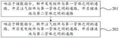
步骤201:响应于储能指令,断开发电组件与第一管体之间的通路,开启注气组件与第一管体之间的通路,开启储液池与第二管体之间的通路。储能阶段,断开发电组件与第一管体之间的通路,开启注气组件与第一管体之间的通路,开启储液池与第二管体之间的通路注气组件可以利用富余电能产生高压空气,高压空气通过第一管体供给到盐穴之中,存到盐穴和沉渣空隙中。盐穴和沉渣空隙的卤水经过第二管体至地面储液池,当卤水被完全排出至地面时,地下盐穴中充满高压空气,断开注气组件和发电组件与第一管体之间的通路,同时断开储液池与第二管体之间的通路,完成储能阶段。可以理解的是,完成储能指令之后应当断开注气组件和发电组件与第一管体之间的通路,同时断开储液池与第二管体之间的通路。Step 201: In response to the energy storage command, disconnect the passage between the power generation component and the first pipe body, open the passage between the gas injection assembly and the first pipe body, and open the passage between the liquid storage tank and the second pipe body . In the energy storage stage, the passage between the power generation component and the first pipe body is disconnected, the passage between the gas injection assembly and the first pipe body is opened, and the passage between the liquid storage tank and the second pipe body is opened. The gas injection assembly can use The excess electric energy generates high-pressure air, which is supplied to the salt cavern through the first pipe body, and stored in the salt cavern and sediment voids. The brine in the salt cavern and sediment void passes through the second pipe body to the ground liquid storage tank. When the brine is completely discharged to the ground, the underground salt cavern is filled with high-pressure air, and the gas injection component and power generation component are disconnected from the first pipe body. At the same time, the passage between the liquid storage tank and the second pipe body is disconnected to complete the energy storage stage. It can be understood that after the energy storage command is completed, the passage between the gas injection component and the power generation component and the first pipe body should be disconnected, and the passage between the liquid storage tank and the second pipe body should be disconnected at the same time.
步骤203:响应于释能指令,断开注气组件与第一管体之间的通路,开启发电组件与第一管体之间的通路,开启储液池与第二管体之间的通路,基于此净空间和盐穴沉渣空间的空气从第一管体排入发电组件发电。Step 203: In response to the energy release command, disconnect the passage between the gas injection component and the first pipe body, open the passage between the power generation component and the first pipe body, and open the passage between the liquid storage tank and the second pipe body , based on this net space and the air in the salt cavern sediment space is discharged from the first pipe body into the power generation component to generate electricity.
通过本申请实施例提供的恒压式压气储能方法可以利用高杂质盐岩地层的沉渣空隙进行压缩空气储能,通过注入空气排出了沉渣空间的卤水,增加了盐穴的有效体积。在盐穴压缩空气储能的初期,注入清水,可以提高采盐量,后期注入饱和卤水,可以避免盐穴进一步溶蚀,同时储液池14的卤水循环利用,解决了卤水的消纳问题。在释放能量阶段,通过向盐穴注入饱和卤水,使盐穴内部保持恒定内压,即提高电能的输出效率,又可以减少洞穴的体积收缩。洞穴底部的沉渣堆积对洞穴壁起到一定支撑作用,可以很大程度上抑制了洞穴的体积收缩。释能阶段完成后,盐穴内部充满卤水,同样抑制洞穴的体积收缩,有利于洞穴的稳定。The constant-pressure compressed air energy storage method provided by the embodiment of the present application can use the sediment voids of high-impurity salt rock formations for compressed air energy storage, and the brine in the sediment space is discharged by injecting air, increasing the effective volume of the salt cavern. In the early stage of compressed air energy storage in salt caverns, injecting clean water can increase the amount of salt produced, and injecting saturated brine later can prevent further corrosion of salt caverns. At the same time, the brine in the
可以理解的是,储能和释能阶段可以进一步划分为初期储能和释能阶段和中后期储能和释能阶段,二者对于注气组件、发电组件和储液池14的导通控制方式一致,在初期释能阶段,断开注气组件与第一管体1之间的通路,开启发电组件与第一管体1之间的通路,开启储液池14与第二管体2之间的通路,盐穴的净空间和沉渣空间的空气从第一管体1排入发电组件发电。同时储液池14的清水沿着第二管体2进入地下盐穴,继续溶解盐穴的水平段,即可以防止后期压气储能运行过程中水平段发生堵塞,又保证了洞穴内部处于恒压状态。当地下盐穴充满卤水时,即完成初期释能阶段。至此,完成了一个完整的初期储能和释能阶段。经过初期的储能和释能阶段,清水溶解盐层后逐渐变成饱和卤水。在后续的中后期释能阶段,断开注气组件与第一管体1之间的通路,开启发电组件与第一管体1之间的通路,开启储液池14与第二管体2之间的通路。盐穴净空间6和盐穴沉渣空间7的空气从第一管体1排入发电组件发电。同时储液池14的饱和卤水沿着第二管体2进入地下盐穴,以保证洞穴内部处于恒压状态。当地下盐穴充满饱和卤水时,即完成释能阶段,至此,完成了一个完整的中后期储能和释能阶段。此阶段,经过第一管体1注入排出的水均为饱和卤水,恒压式压气储能系统中的卤水实现了循环利用。It can be understood that the energy storage and energy release stage can be further divided into the initial energy storage and energy release stage and the middle and late energy storage and energy release stage. In the same way, in the initial stage of energy release, the passage between the gas injection component and the first pipe body 1 is disconnected, the passage between the power generation assembly and the first pipe body 1 is opened, and the
在一种可行的实施方式中,响应于储能指令,断开发电组件与第一管体1之间的通路,开启注气组件与第一管体1之间的通路,开启储液池14与第二管体2之间的通路的步骤包括:In a feasible implementation, in response to the energy storage instruction, the passage between the power generation component and the first pipe body 1 is disconnected, the passage between the gas injection assembly and the first pipe body 1 is opened, and the
响应于储能指令,断开发电组件与第一管体1之间的通路,开启注气组件与第一管体1之间的通路,使得第一管体1连通于蓄热模块,以使蓄热模块与气体换热,换热之后的气体供给到盐穴,开启储液池14与第二管体2之间的通路。In response to the energy storage instruction, the passage between the power generation component and the first pipe body 1 is disconnected, and the passage between the gas injection assembly and the first pipe body 1 is opened, so that the first pipe body 1 communicates with the heat storage module, so that The heat storage module exchanges heat with the gas, and the gas after heat exchange is supplied to the salt cavern, and the passage between the
在一种可行的实施方式中,响应于释能指令,断开注气组件与第一管体1之间的通路,开启发电组件与第一管体1之间的通路,开启储液池14与第二管体2之间的通路的步骤包括:In a feasible implementation, in response to the energy release instruction, the passage between the gas injection assembly and the first pipe body 1 is disconnected, the passage between the power generation assembly and the first pipe body 1 is opened, and the
断开注气组件与第一管体1之间的通路,开启发电组件与第一管体1之间的通路,以使蓄热模块与气体换热,换热之后的气体供给到发电组件,开启储液池14与第二管体2之间的通路。Disconnect the passage between the gas injection assembly and the first pipe body 1, open the passage between the power generation assembly and the first pipe body 1, so that the heat storage module exchanges heat with the gas, and the gas after heat exchange is supplied to the power generation assembly, The passage between the
在储能阶段压缩机产生的高温高压气体可以通过蓄热模块之后再供给到盐穴之内,蓄热模块可以与高温高压气体通过蓄热管17进行供给,蓄热管17与蓄热材料16进行换热,蓄热模块对热能进行存储,而后高压低温的气体再供给到盐穴内;在释能阶段,高压低温气体经由盐穴输出,高压低温气体通过蓄热管17进行供给,与蓄热材料16进行换热,转换为高温高压气体后输入到发电组件进行发电,基于此可以对热能进行存储和利用,可以提高发电效率。In the energy storage stage, the high-temperature and high-pressure gas generated by the compressor can pass through the heat storage module and then be supplied into the salt cavern. Heat, the heat storage module stores heat energy, and then the high-pressure and low-temperature gas is supplied to the salt cave; in the energy release stage, the high-pressure and low-temperature gas is output through the salt cave, and the high-pressure and low-temperature gas is supplied through the heat storage tube 17, and the
如图1所示,在一些示例中,本申请实施例提供的恒压式压气储能方法可以包括:As shown in Figure 1, in some examples, the constant-pressure pressurized gas energy storage method provided by the embodiment of the present application may include:
在已完成水溶造腔的盐穴附近200m,开凿一口新井作为第一管体1,通过定向钻井技术与初始盐穴连通。A new well is dug 200m near the salt cavern that has completed water-solution cavity creation as the first pipe body 1, and is connected to the initial salt cavern by directional drilling technology.
在第一管体1距地表3大约50m处,在非盐岩层4中开挖地下蓄热硐室用于设置蓄热模块。蓄热模块的壳体15由绝热陶瓷、蓄热材料16(高温熔融盐)和蓄热管17组成。壳体15表面采用绝热陶瓷材料避免蓄热系统的热量散失,蓄热硐室内部充满高温熔融盐可以储存大量热量,空气经过蓄热管17完成蓄热和放热。At a place where the first pipe body 1 is about 50m away from the ground surface 3, an underground heat storage chamber is excavated in the
在初期储能阶段,打开第一控制阀18和第三阀门,关闭第二阀门。利用电网9中的富余电能,带动电动机10和空气压缩机12运行,产生的高压高温空气进入蓄热系统的蓄热管17,高温高压空气的热量被储存在蓄热材料16(高温熔融盐)中,蓄热系统排出的高压低温空气依次进入蓄热系统的蓄热管17,盐穴净空间6、盐穴沉渣空间7中。盐穴内的卤水在高压空气的作用下,通过第二管体2排出至地面储液池14。当卤水被完全排出至地面时,地下盐穴中充满高压空气,关闭所有阀门,完成储能阶段。In the initial energy storage stage, the
初期释能阶段,打开第二阀门和第三阀门,关闭第一控制阀18。盐穴净空间6和盐穴沉渣空间7的高压空气从第一管体1进入蓄热系统的蓄热管17,高压空气被蓄热材料16(高温熔融盐)加热形成高温高压空气,经第一管体1进入膨胀机13,带动发电机11发电。同时储液池14的淡水沿着注第二管体2进入地下盐穴,继续溶解水平段8,注入淡水即可以防止后期压缩空气储能运行过程中水平段发生堵塞,又保证了洞穴内部处于恒压状态。当地下盐穴充满卤水时,即完成释能阶段。至此,完成了一个完整的初期储能和释能阶段。经过初期的储能和释能阶段,淡水溶解盐层后逐渐变成饱和卤水。In the initial stage of energy release, the second valve and the third valve are opened, and the
中后期储能阶段,打开第一控制阀18和第三控制阀20,关闭第二控制阀19。利用电网9中的富余电能,带动电动机10和空气压缩机12运行,产生的高压高温空气进入蓄热系统的蓄热管17,高温高压空气的热量被储存在蓄热材料16(高温熔融盐)中,蓄热系统排出的高压低温空气依次进入盐穴净空间6、盐穴沉渣空间7中。盐穴内部的饱和卤水在空气压力的作用下,经过注排水管排出至地面蓄水池。当饱和卤水被完全排出至地面时,地下盐穴中充满高压空气,关闭所有阀门,完成储能阶段。In the middle and late stages of energy storage, the
中后期释能阶段,打开第二控制阀19和第三控制阀20,关闭第一控制阀18。盐穴净空间6和盐穴沉渣空间7的高压空气从第一管体1进入蓄热系统的蓄热管17,高压空气被蓄热材料16(高温熔融盐)加热形成高温高压空气,经第一管体1进入膨胀机13,带动发电机11发电。同时蓄水池的饱和卤水沿着第二管体2进入地下盐穴,以保证洞穴内部处于恒压状态。当地下盐穴充满饱和卤水时,即完成释能阶段。至此,完成了一个完整的中后期储能和释能阶段。此阶段,经过注排水管注入排出的水均为饱和卤水。高杂质盐矿的恒压式压缩空气储能系统中的卤水实现了循环利用。In the middle and late stages of energy release, the
在该技术方案中,利用蓄热材料16用于储存压缩空气过程产生的压缩热,整个系统的储能效率可以提高至70%以上。同时利用盐穴沉渣空间7进行压缩空气储能,可以大大提高盐穴的可用体积,实现电网9的“削峰填谷”,提高可再生能源的利用率。In this technical solution, the
如图3所示,根据本申请实施例的第三方面提出了一种计算机可读存储介质301,计算机可读存储介质301存储有计算机程序302,实现如上述技术方案的恒压式压气储能方法。As shown in Figure 3, according to the third aspect of the embodiment of the present application, a computer-readable storage medium 301 is proposed, and the computer-readable storage medium 301 stores a computer program 302 to realize the constant-pressure compressed air energy storage as in the above-mentioned technical solution method.
通过本申请实施例提供的计算机可读存储介质301可以利用高杂质盐岩地层的沉渣空隙进行压缩空气储能,通过注入空气排出了沉渣空间的卤水,增加了盐穴的有效体积。在盐穴压缩空气储能的初期,注入清水,可以提高采盐量,后期注入饱和卤水,可以避免盐穴进一步溶蚀,同时储液池的卤水循环利用,解决了卤水的消纳问题。在释放能量阶段,通过向盐穴注入饱和卤水,使盐穴内部保持恒定内压,即提高电能的输出效率,又可以减少洞穴的体积收缩。洞穴底部的沉渣堆积对洞穴壁起到一定支撑作用,可以很大程度上抑制了洞穴的体积收缩。释能阶段完成后,盐穴内部充满卤水,同样抑制洞穴的体积收缩,有利于洞穴的稳定。The computer-readable storage medium 301 provided by the embodiment of the present application can use the sediment voids of high-impurity salt rock formations for compressed air energy storage, and the brine in the sediment space is discharged by injecting air, increasing the effective volume of the salt cavern. In the initial stage of compressed air energy storage in salt caverns, injecting clean water can increase the amount of salt produced, and injecting saturated brine in the later stage can avoid further corrosion of salt caverns. At the same time, the brine in the liquid storage tank is recycled to solve the problem of brine consumption. In the stage of releasing energy, by injecting saturated brine into the salt cavern, the interior pressure of the salt cavern is kept constant, which not only improves the output efficiency of electric energy, but also reduces the volume shrinkage of the cavern. The sediment accumulation at the bottom of the cave plays a certain role in supporting the cave wall, which can largely restrain the volume shrinkage of the cave. After the energy release stage is completed, the interior of the salt cave is filled with brine, which also inhibits the volume shrinkage of the cave and is conducive to the stability of the cave.
基于这样的理解,本申请的技术方案可以以软件产品的形式体现出来,该软件产品可以存储在一个非易失性存储介质(可以是CD-ROM,U盘,移动硬盘等)中,包括若干指令用以使得一台计算机设备(可以是个人计算机,服务器,或者网络设备等)执行本申请各个实施场景所述的方法。Based on this understanding, the technical solution of the present application can be embodied in the form of software products, which can be stored in a non-volatile storage medium (which can be CD-ROM, U disk, mobile hard disk, etc.), including several The instructions are used to make a computer device (which may be a personal computer, a server, or a network device, etc.) execute the methods described in various implementation scenarios of the present application.
如图4所示,根据本申请实施例的第四方面提出了一种控制装置,包括:存储器401,存储有计算机程序;处理器402,执行计算机程序;其中,处理器402在执行计算机程序时,实现如上述技术方案的恒压式压气储能方法。As shown in FIG. 4 , according to the fourth aspect of the embodiment of the present application, a control device is proposed, including: a memory 401 storing a computer program; a processor 402 executing the computer program; wherein, when the processor 402 executes the computer program , realizing the constant-pressure compressed air energy storage method as in the above technical solution.
通过本申请实施例提供的控制装置可以利用高杂质盐岩地层的沉渣空隙进行压缩空气储能,通过注入空气排出了沉渣空间的卤水,增加了盐穴的有效体积。在盐穴压缩空气储能的初期,注入清水,可以提高采盐量,后期注入饱和卤水,可以避免盐穴进一步溶蚀,同时储液池的卤水循环利用,解决了卤水的消纳问题。在释放能量阶段,通过向盐穴注入饱和卤水,使盐穴内部保持恒定内压,即提高电能的输出效率,又可以减少洞穴的体积收缩。洞穴底部的沉渣堆积对洞穴壁起到一定支撑作用,可以很大程度上抑制了洞穴的体积收缩。释能阶段完成后,盐穴内部充满卤水,同样抑制洞穴的体积收缩,有利于洞穴的稳定。The control device provided by the embodiment of the present application can use the sediment space of the high-impurity salt rock formation for compressed air energy storage, and the brine in the sediment space is discharged by injecting air, increasing the effective volume of the salt cavern. In the initial stage of compressed air energy storage in salt caverns, injecting clean water can increase the amount of salt produced, and injecting saturated brine in the later stage can avoid further corrosion of salt caverns. At the same time, the brine in the liquid storage tank is recycled to solve the problem of brine consumption. In the stage of releasing energy, by injecting saturated brine into the salt cavern, the interior pressure of the salt cavern is kept constant, which not only improves the output efficiency of electric energy, but also reduces the volume shrinkage of the cavern. The sediment accumulation at the bottom of the cave plays a certain role in supporting the cave wall, which can largely restrain the volume shrinkage of the cave. After the energy release stage is completed, the interior of the salt cave is filled with brine, which also inhibits the volume shrinkage of the cave and is conducive to the stability of the cave.
在一些示例中,该控制装置还可以包括用户接口、网络接口、摄像头、射频(RadioFrequency,RF)电路,传感器、音频电路、WI-FI模块等等。用户接口可以包括显示屏(Display)、输入单元比如键盘(Keyboard)等,可选用户接口还可以包括USB接口、读卡器接口等。网络接口可选的可以包括标准的有线接口、无线接口(如WI-FI接口)等。In some examples, the control device may further include a user interface, a network interface, a camera, a radio frequency (Radio Frequency, RF) circuit, a sensor, an audio circuit, a WI-FI module, and the like. The user interface may include a display screen (Display), an input unit such as a keyboard (Keyboard), and the like, and optional user interfaces may also include a USB interface, a card reader interface, and the like. Optionally, the network interface may include a standard wired interface, a wireless interface (such as a WI-FI interface), and the like.
在示例性实施例中,控制装置还可以包括:输入输出接口和显示设备,其中,各个功能单元之间可以通过总线完成相互间的通信。该存储器存储有计算机程序,处理器,用于执行存储器上所存放的程序,执行上述实施例中的方法。In an exemplary embodiment, the control device may further include: an input and output interface and a display device, wherein the communication between each functional unit may be completed through a bus. The memory stores computer programs, and the processor is used to execute the programs stored in the memory and execute the methods in the above-mentioned embodiments.
上述存储介质中还可以包括操作系统、网络通信模块。操作系统是管理上述方法的实体设备硬件和软件资源的程序,支持信息处理程序以及其它软件和/或程序的运行。网络通信模块用于实现存储介质内部各组件之间的通信,以及与信息处理实体设备中其它硬件和软件之间通信。The above storage medium may also include an operating system and a network communication module. The operating system is a program that manages the hardware and software resources of the physical device of the above method, and supports the operation of information processing programs and other software and/or programs. The network communication module is used to realize the communication between various components inside the storage medium, and communicate with other hardware and software in the information processing entity device.
通过以上的实施方式的描述,本领域的技术人员可以清楚地了解到本申请可以借助软件加必要的通用硬件平台的方式来实现,也可以通过硬件实现。Through the above description of the embodiments, those skilled in the art can clearly understand that the present application can be realized by means of software plus a necessary general-purpose hardware platform, or by hardware.
本申请是参照根据本申请实施例的方法、设备(系统)、和计算机程序产品的流程图和/或方框图来描述。应理解可由计算机程序指令实现流程图和/或方框图中的每一流程和/或方框、以及流程图和/或方框图中的流程和/或方框的结合。可提供这些计算机程序指令到通用计算机、专用计算机、嵌入式计算机或者其他可编程数据处理设备的处理器以产生一个机器,使得通过计算机或其他可编程数据处理设备的处理器执行的指令产生用于实现在流程图一个流程或多个流程和/或方框图一个方框或多个方框中指定的功能的装置。The present application is described with reference to flowcharts and/or block diagrams of methods, apparatus (systems), and computer program products according to embodiments of the present application. It should be understood that each procedure and/or block in the flowchart and/or block diagram, and a combination of procedures and/or blocks in the flowchart and/or block diagram can be realized by computer program instructions. These computer program instructions may be provided to a processor of a general purpose computer, special purpose computer, embedded computer, or other programmable data processing device to produce a machine such that the instructions executed by the processor of the computer or other programmable data processing device produce a machine for A device for realizing the functions specified in one or more procedures of a flowchart and/or one or more blocks of a block diagram.
在本发明中,术语“第一”、“第二”、“第三”仅用于描述的目的,而不能理解为指示或暗示相对重要性;术语“多个”则指两个或两个以上,除非另有明确的限定。术语“安装”、“相连”、“连接”、“固定”等术语均应做广义理解,例如,“连接”可以是固定连接,也可以是可拆卸连接,或一体地连接;“相连”可以是直接相连,也可以通过中间媒介间接相连。对于本领域的普通技术人员而言,可以根据具体情况理解上述术语在本发明中的具体含义。In the present invention, the terms "first", "second", and "third" are only used for descriptive purposes, and cannot be understood as indicating or implying relative importance; the term "plurality" refers to two or two above, unless expressly defined otherwise. The terms "installation", "connection", "connection", "fixed" and other terms should be interpreted in a broad sense, for example, "connection" can be fixed connection, detachable connection, or integral connection; "connection" can be directly or indirectly through an intermediary. Those of ordinary skill in the art can understand the specific meanings of the above terms in the present invention according to specific situations.
本发明的描述中,需要理解的是,术语“上”、“下”、“左”、“右”、“前”、“后”等指示的方位或位置关系为基于附图所示的方位或位置关系,仅是为了便于描述本发明和简化描述,而不是指示或暗示所指的装置或单元必须具有特定的方向、以特定的方位构造和操作,因此,不能理解为对本发明的限制。In the description of the present invention, it should be understood that the orientation or positional relationship indicated by the terms "upper", "lower", "left", "right", "front", "rear" etc. is based on the orientation shown in the drawings Or positional relationship is only for the convenience of describing the present invention and simplifying the description, but does not indicate or imply that the referred device or unit must have a specific direction, be constructed and operated in a specific orientation, and therefore, should not be construed as a limitation of the present invention.
在本说明书的描述中,术语“一个实施例”、“一些实施例”、“具体实施例”等的描述意指结合该实施例或示例描述的具体特征、结构、材料或特点包含于本发明的至少一个实施例或示例中。在本说明书中,对上述术语的示意性表述不一定指的是相同的实施例或实例。而且,描述的具体特征、结构、材料或特点可以在任何的一个或多个实施例或示例中以合适的方式结合。In the description of this specification, descriptions of the terms "one embodiment", "some embodiments", "specific embodiments" and the like mean that specific features, structures, materials or characteristics described in conjunction with the embodiment or example are included in the present invention In at least one embodiment or example of . In this specification, schematic representations of the above terms do not necessarily refer to the same embodiment or example. Furthermore, the specific features, structures, materials or characteristics described may be combined in any suitable manner in any one or more embodiments or examples.
以上仅为本发明的优选实施例而已,并不用于限制本发明,对于本领域的技术人员来说,本发明可以有各种更改和变化。凡在本发明的精神和原则之内,所作的任何修改、等同替换、改进等,均应包含在本发明的保护范围之内。The above are only preferred embodiments of the present invention, and are not intended to limit the present invention. For those skilled in the art, the present invention may have various modifications and changes. Any modifications, equivalent replacements, improvements, etc. made within the spirit and principles of the present invention shall be included within the protection scope of the present invention.
Claims (10)
Translated fromChinesePriority Applications (1)
| Application Number | Priority Date | Filing Date | Title |
|---|---|---|---|
| CN202310386007.0ACN116357552A (en) | 2023-04-12 | 2023-04-12 | Constant pressure compressed gas energy storage method, system and related equipment |
Applications Claiming Priority (1)
| Application Number | Priority Date | Filing Date | Title |
|---|---|---|---|
| CN202310386007.0ACN116357552A (en) | 2023-04-12 | 2023-04-12 | Constant pressure compressed gas energy storage method, system and related equipment |
Publications (1)
| Publication Number | Publication Date |
|---|---|
| CN116357552Atrue CN116357552A (en) | 2023-06-30 |
Family
ID=86938586
Family Applications (1)
| Application Number | Title | Priority Date | Filing Date |
|---|---|---|---|
| CN202310386007.0APendingCN116357552A (en) | 2023-04-12 | 2023-04-12 | Constant pressure compressed gas energy storage method, system and related equipment |
Country Status (1)
| Country | Link |
|---|---|
| CN (1) | CN116357552A (en) |
Cited By (1)
| Publication number | Priority date | Publication date | Assignee | Title |
|---|---|---|---|---|
| CN119412154A (en)* | 2024-11-18 | 2025-02-11 | 中国科学院武汉岩土力学研究所 | A salt cave brine circulation fissure repair system and repair method |
Citations (7)
| Publication number | Priority date | Publication date | Assignee | Title |
|---|---|---|---|---|
| CN108561293A (en)* | 2018-03-29 | 2018-09-21 | 华北电力大学 | A kind of method and system improving LAES system effectivenesies and response speed |
| CN109973362A (en)* | 2019-03-29 | 2019-07-05 | 西安交通大学 | Composite compressed air energy storage system and method based on double-well structure thermal salt well |
| CN110259662A (en)* | 2019-05-21 | 2019-09-20 | 西安交通大学 | Additional mechanical supercharging reheat-type compressed-air energy-storage system and method based on the hot salt well of twin-well structure |
| CN110749223A (en)* | 2019-10-17 | 2020-02-04 | 国网安徽省电力有限公司 | Access shared compressed air energy storage and heat storage system |
| CN113982892A (en)* | 2021-10-26 | 2022-01-28 | 中国科学院工程热物理研究所 | High-temperature heat accumulating type compressed air energy storage system |
| CN114017116A (en)* | 2021-09-28 | 2022-02-08 | 宁波大学 | A coupling system of atmospheric pressure gas energy storage and salt mining and heat mining |
| CN115434675A (en)* | 2022-09-09 | 2022-12-06 | 中国科学院武汉岩土力学研究所 | No bottom gas injection and production device and operation method of sediment void type gas storage |
- 2023
- 2023-04-12CNCN202310386007.0Apatent/CN116357552A/enactivePending
Patent Citations (7)
| Publication number | Priority date | Publication date | Assignee | Title |
|---|---|---|---|---|
| CN108561293A (en)* | 2018-03-29 | 2018-09-21 | 华北电力大学 | A kind of method and system improving LAES system effectivenesies and response speed |
| CN109973362A (en)* | 2019-03-29 | 2019-07-05 | 西安交通大学 | Composite compressed air energy storage system and method based on double-well structure thermal salt well |
| CN110259662A (en)* | 2019-05-21 | 2019-09-20 | 西安交通大学 | Additional mechanical supercharging reheat-type compressed-air energy-storage system and method based on the hot salt well of twin-well structure |
| CN110749223A (en)* | 2019-10-17 | 2020-02-04 | 国网安徽省电力有限公司 | Access shared compressed air energy storage and heat storage system |
| CN114017116A (en)* | 2021-09-28 | 2022-02-08 | 宁波大学 | A coupling system of atmospheric pressure gas energy storage and salt mining and heat mining |
| CN113982892A (en)* | 2021-10-26 | 2022-01-28 | 中国科学院工程热物理研究所 | High-temperature heat accumulating type compressed air energy storage system |
| CN115434675A (en)* | 2022-09-09 | 2022-12-06 | 中国科学院武汉岩土力学研究所 | No bottom gas injection and production device and operation method of sediment void type gas storage |
Cited By (2)
| Publication number | Priority date | Publication date | Assignee | Title |
|---|---|---|---|---|
| CN119412154A (en)* | 2024-11-18 | 2025-02-11 | 中国科学院武汉岩土力学研究所 | A salt cave brine circulation fissure repair system and repair method |
| CN119412154B (en)* | 2024-11-18 | 2025-09-12 | 中国科学院武汉岩土力学研究所 | A salt cave brine circulation crack repair system and repair method |
Similar Documents
| Publication | Publication Date | Title |
|---|---|---|
| King et al. | Overview of current compressed air energy storage projects and analysis of the potential underground storage capacity in India and the UK | |
| Succar et al. | Compressed air energy storage: theory, resources, and applications for wind power | |
| US7663255B2 (en) | Compressed-air-storing electricity generating system and electricity generating method using the same | |
| US10767936B2 (en) | Trans-seasonal cold-storage heat-storage system | |
| US20210024290A1 (en) | System and method for compressed air energy storage | |
| CN106499612A (en) | Compressed air double-energy storage system without external heat source | |
| CN108895017A (en) | Multistage constant voltage compressed air energy memory | |
| CN109973362B (en) | Combined type compressed air energy storage system and method based on double-well structure hot salt well | |
| CN108953121A (en) | From back pressure constant pressure compressed-air energy-storage system and method | |
| CN103353060A (en) | Constant-temperature gas storage system applied to compressed air energy storage power generation system | |
| CN116357552A (en) | Constant pressure compressed gas energy storage method, system and related equipment | |
| CN116816648A (en) | Compressed air combined storage co-heating system, power system and compressed air energy storage method | |
| CN116608091B (en) | Onshore wind turbine generator set and energy storage system | |
| CN111219186B (en) | Method for storing compressed gas energy by utilizing deep aquifer | |
| CN114635842A (en) | Piston type constant-pressure compressed air energy storage system and using method thereof | |
| CN115234329A (en) | A closed-cycle compression energy storage power generation system and its operation method | |
| Saaly et al. | Thermal imbalance due to application of geothermal energy piles and mitigation strategies for sustainable development in cold regions: a review | |
| CN118842193A (en) | Liquid carbon dioxide energy storage system | |
| CN114658504A (en) | A multi-stage compressed air energy storage and heat pump power storage coupled energy storage system | |
| Qin et al. | A variable pressure water-sealed compressed air energy storage (CAES) tunnel excavated in the seabed: Concept and airtightness evaluation | |
| CN111878168B (en) | Method and system for storing natural gas and supplying heat by using abandoned mine | |
| US20240060602A1 (en) | Systems and methods for heat management for cased wellbore compressed air storage | |
| CN213362907U (en) | Geothermal resource compensation type recharge system | |
| Jiang et al. | Simulation study of a novel approach to couple compressed CO2 energy storage with compression heat storage in aquifers | |
| CN212104046U (en) | A large-diameter artificially excavated hollow pile for cold storage and heat exchange |
Legal Events
| Date | Code | Title | Description |
|---|---|---|---|
| PB01 | Publication | ||
| PB01 | Publication | ||
| SE01 | Entry into force of request for substantive examination | ||
| SE01 | Entry into force of request for substantive examination |