CN116350394A - Seal, seal assembly, control assembly, and valve clip delivery device - Google Patents
Seal, seal assembly, control assembly, and valve clip delivery deviceDownload PDFInfo
- Publication number
- CN116350394A CN116350394ACN202111633714.2ACN202111633714ACN116350394ACN 116350394 ACN116350394 ACN 116350394ACN 202111633714 ACN202111633714 ACN 202111633714ACN 116350394 ACN116350394 ACN 116350394A
- Authority
- CN
- China
- Prior art keywords
- control
- sealing ring
- control rod
- valve
- lock
- Prior art date
- Legal status (The legal status is an assumption and is not a legal conclusion. Google has not performed a legal analysis and makes no representation as to the accuracy of the status listed.)
- Pending
Links
Images


Classifications
- A—HUMAN NECESSITIES
- A61—MEDICAL OR VETERINARY SCIENCE; HYGIENE
- A61F—FILTERS IMPLANTABLE INTO BLOOD VESSELS; PROSTHESES; DEVICES PROVIDING PATENCY TO, OR PREVENTING COLLAPSING OF, TUBULAR STRUCTURES OF THE BODY, e.g. STENTS; ORTHOPAEDIC, NURSING OR CONTRACEPTIVE DEVICES; FOMENTATION; TREATMENT OR PROTECTION OF EYES OR EARS; BANDAGES, DRESSINGS OR ABSORBENT PADS; FIRST-AID KITS
- A61F2/00—Filters implantable into blood vessels; Prostheses, i.e. artificial substitutes or replacements for parts of the body; Appliances for connecting them with the body; Devices providing patency to, or preventing collapsing of, tubular structures of the body, e.g. stents
- A61F2/02—Prostheses implantable into the body
- A61F2/24—Heart valves ; Vascular valves, e.g. venous valves; Heart implants, e.g. passive devices for improving the function of the native valve or the heart muscle; Transmyocardial revascularisation [TMR] devices; Valves implantable in the body
- A61F2/2442—Annuloplasty rings or inserts for correcting the valve shape; Implants for improving the function of a native heart valve
- A61F2/2466—Delivery devices therefor
- A—HUMAN NECESSITIES
- A61—MEDICAL OR VETERINARY SCIENCE; HYGIENE
- A61F—FILTERS IMPLANTABLE INTO BLOOD VESSELS; PROSTHESES; DEVICES PROVIDING PATENCY TO, OR PREVENTING COLLAPSING OF, TUBULAR STRUCTURES OF THE BODY, e.g. STENTS; ORTHOPAEDIC, NURSING OR CONTRACEPTIVE DEVICES; FOMENTATION; TREATMENT OR PROTECTION OF EYES OR EARS; BANDAGES, DRESSINGS OR ABSORBENT PADS; FIRST-AID KITS
- A61F2/00—Filters implantable into blood vessels; Prostheses, i.e. artificial substitutes or replacements for parts of the body; Appliances for connecting them with the body; Devices providing patency to, or preventing collapsing of, tubular structures of the body, e.g. stents
- A61F2/02—Prostheses implantable into the body
- A61F2/24—Heart valves ; Vascular valves, e.g. venous valves; Heart implants, e.g. passive devices for improving the function of the native valve or the heart muscle; Transmyocardial revascularisation [TMR] devices; Valves implantable in the body
- A61F2/2427—Devices for manipulating or deploying heart valves during implantation
- A61F2/2436—Deployment by retracting a sheath
- A—HUMAN NECESSITIES
- A61—MEDICAL OR VETERINARY SCIENCE; HYGIENE
- A61F—FILTERS IMPLANTABLE INTO BLOOD VESSELS; PROSTHESES; DEVICES PROVIDING PATENCY TO, OR PREVENTING COLLAPSING OF, TUBULAR STRUCTURES OF THE BODY, e.g. STENTS; ORTHOPAEDIC, NURSING OR CONTRACEPTIVE DEVICES; FOMENTATION; TREATMENT OR PROTECTION OF EYES OR EARS; BANDAGES, DRESSINGS OR ABSORBENT PADS; FIRST-AID KITS
- A61F2/00—Filters implantable into blood vessels; Prostheses, i.e. artificial substitutes or replacements for parts of the body; Appliances for connecting them with the body; Devices providing patency to, or preventing collapsing of, tubular structures of the body, e.g. stents
- A61F2/02—Prostheses implantable into the body
- A61F2/24—Heart valves ; Vascular valves, e.g. venous valves; Heart implants, e.g. passive devices for improving the function of the native valve or the heart muscle; Transmyocardial revascularisation [TMR] devices; Valves implantable in the body
- A61F2/2427—Devices for manipulating or deploying heart valves during implantation
- A61F2/2439—Expansion controlled by filaments
- A—HUMAN NECESSITIES
- A61—MEDICAL OR VETERINARY SCIENCE; HYGIENE
- A61F—FILTERS IMPLANTABLE INTO BLOOD VESSELS; PROSTHESES; DEVICES PROVIDING PATENCY TO, OR PREVENTING COLLAPSING OF, TUBULAR STRUCTURES OF THE BODY, e.g. STENTS; ORTHOPAEDIC, NURSING OR CONTRACEPTIVE DEVICES; FOMENTATION; TREATMENT OR PROTECTION OF EYES OR EARS; BANDAGES, DRESSINGS OR ABSORBENT PADS; FIRST-AID KITS
- A61F2/00—Filters implantable into blood vessels; Prostheses, i.e. artificial substitutes or replacements for parts of the body; Appliances for connecting them with the body; Devices providing patency to, or preventing collapsing of, tubular structures of the body, e.g. stents
- A61F2/02—Prostheses implantable into the body
- A61F2/24—Heart valves ; Vascular valves, e.g. venous valves; Heart implants, e.g. passive devices for improving the function of the native valve or the heart muscle; Transmyocardial revascularisation [TMR] devices; Valves implantable in the body
- A61F2/2442—Annuloplasty rings or inserts for correcting the valve shape; Implants for improving the function of a native heart valve
- A61F2/246—Devices for obstructing a leak through a native valve in a closed condition
- A—HUMAN NECESSITIES
- A61—MEDICAL OR VETERINARY SCIENCE; HYGIENE
- A61F—FILTERS IMPLANTABLE INTO BLOOD VESSELS; PROSTHESES; DEVICES PROVIDING PATENCY TO, OR PREVENTING COLLAPSING OF, TUBULAR STRUCTURES OF THE BODY, e.g. STENTS; ORTHOPAEDIC, NURSING OR CONTRACEPTIVE DEVICES; FOMENTATION; TREATMENT OR PROTECTION OF EYES OR EARS; BANDAGES, DRESSINGS OR ABSORBENT PADS; FIRST-AID KITS
- A61F2210/00—Particular material properties of prostheses classified in groups A61F2/00 - A61F2/26 or A61F2/82 or A61F9/00 or A61F11/00 or subgroups thereof
- A61F2210/0014—Particular material properties of prostheses classified in groups A61F2/00 - A61F2/26 or A61F2/82 or A61F9/00 or A61F11/00 or subgroups thereof using shape memory or superelastic materials, e.g. nitinol
- Y—GENERAL TAGGING OF NEW TECHNOLOGICAL DEVELOPMENTS; GENERAL TAGGING OF CROSS-SECTIONAL TECHNOLOGIES SPANNING OVER SEVERAL SECTIONS OF THE IPC; TECHNICAL SUBJECTS COVERED BY FORMER USPC CROSS-REFERENCE ART COLLECTIONS [XRACs] AND DIGESTS
- Y02—TECHNOLOGIES OR APPLICATIONS FOR MITIGATION OR ADAPTATION AGAINST CLIMATE CHANGE
- Y02E—REDUCTION OF GREENHOUSE GAS [GHG] EMISSIONS, RELATED TO ENERGY GENERATION, TRANSMISSION OR DISTRIBUTION
- Y02E30/00—Energy generation of nuclear origin
- Y02E30/30—Nuclear fission reactors
Landscapes
- Health & Medical Sciences (AREA)
- Cardiology (AREA)
- Oral & Maxillofacial Surgery (AREA)
- Transplantation (AREA)
- Engineering & Computer Science (AREA)
- Biomedical Technology (AREA)
- Heart & Thoracic Surgery (AREA)
- Vascular Medicine (AREA)
- Life Sciences & Earth Sciences (AREA)
- Animal Behavior & Ethology (AREA)
- General Health & Medical Sciences (AREA)
- Public Health (AREA)
- Veterinary Medicine (AREA)
- Surgical Instruments (AREA)
Abstract
Translated fromChinese
Description
Translated fromChinese技术领域technical field
本申请涉及医疗器械技术领域,特别涉及一种密封件、密封组件、控制组件及瓣膜夹输送装置。The present application relates to the technical field of medical devices, in particular to a seal, a seal assembly, a control assembly and a valve clip delivery device.
背景技术Background technique
二尖瓣是位于心脏左心房与左心室之间的单向阀,正常健康的二尖瓣可以控制血液从左心房流到左心室,同时避免血液从左心室流到左心房。二尖瓣包括一对瓣叶,称为前叶及后叶。正常情况下,心脏左心室收缩时,前叶和后叶的边缘完全对合,避免血液从左心室流到左心房。当二尖瓣的瓣叶或腱索、瓣环等发生病变时,如腱索部分断裂,二尖瓣的前叶和后叶对合不良,那么当心脏左心室收缩时,二尖瓣不能完全关闭,导致血液从左心室反流至左心房,从而引起一系列的病理生理改变,称为“二尖瓣反流”。The mitral valve is a one-way valve between the heart's left atrium and left ventricle. A normal, healthy mitral valve controls blood flow from the left atrium to the left ventricle while preventing blood from flowing from the left ventricle to the left atrium. The mitral valve consists of a pair of leaflets called the anterior and posterior leaflets. Under normal circumstances, when the left ventricle of the heart contracts, the edges of the anterior and posterior lobes are completely joined to prevent blood from flowing from the left ventricle to the left atrium. When the mitral valve leaflets or chordae, valve ring, etc. have lesions, such as partial rupture of the chordae and poor alignment of the anterior and posterior leaflets of the mitral valve, then when the left ventricle of the heart contracts, the mitral valve cannot fully Closed, causing blood to flow back from the left ventricle to the left atrium, causing a series of pathophysiological changes called "mitral regurgitation".
二尖瓣的缘对缘修复是治疗二尖瓣反流的有效方法,具体是将二尖瓣的前叶和后叶不能正常对合的边缘通过缝合或夹合等方式固定在一起,从而缩小瓣叶间隙,使得二尖瓣瓣口形成双孔化结构,以减小二尖瓣瓣口的总面积,减少或者消除反流量。传统二尖瓣缘对缘修复术是在开刀直视条件下操作,通常需要开胸和建立血液体外循环,因此风险较高。随着技术的进步,已经发展出各种微创手术及介入手术,这类手术只需在患者身体上切开较小的操作窗口,由此利用输送装置将瓣膜夹递送至发生病变的二尖瓣,瓣膜夹将两片瓣叶的部分边缘夹持固定在一起,二尖瓣瓣口形成双孔化结构,从而减小反流。The edge-to-edge repair of the mitral valve is an effective method for the treatment of mitral regurgitation. Specifically, the edges of the anterior leaflet and the posterior leaflet of the mitral valve that cannot be normally aligned are fixed together by suturing or clipping, thereby reducing the size of the mitral valve. The valve leaflet gap makes the mitral valve orifice form a double-hole structure, so as to reduce the total area of the mitral valve orifice and reduce or eliminate the regurgitation flow. Traditional mitral valve edge-to-edge repair is performed under direct vision, and usually requires thoracotomy and establishment of extracorporeal circulation, so the risk is relatively high. With the advancement of technology, various minimally invasive and interventional procedures have been developed, which only need to cut a small operating window on the patient's body, and then use the delivery device to deliver the valve clip to the diseased mitral The valve clip clamps and fixes part of the edges of the two leaflets together, and the mitral valve orifice forms a double-hole structure, thereby reducing regurgitation.
瓣膜夹输送装置中尤其是手柄上存在多种形式的轴孔配合类元件,如螺杆与螺帽、可移动杆与套筒等,为了避免气体进入装置及防止血液外漏,需要对轴孔类元件的配合处进行密封。常规的密封圈,当需要取下密封圈时,通常需要使用镊子、钳子等辅助工具进行夹取,手术操作较为繁琐且不方便,延长了手术时间。In the valve clip delivery device, especially on the handle, there are various forms of shaft-hole matching components, such as screws and nuts, movable rods and sleeves, etc. In order to prevent gas from entering the device and prevent blood leakage, it is necessary to align the shaft holes. The joints of the components are sealed. When the conventional sealing ring needs to be removed, it is usually necessary to use auxiliary tools such as tweezers and pliers to clamp it. The operation is cumbersome and inconvenient, which prolongs the operation time.
发明内容Contents of the invention
本申请的目的在于提供一种密封件、密封组件、控制组件及瓣膜夹输送装置,以解决常规密封圈所导致的手术操作繁琐、耗时较长的问题。The purpose of the present application is to provide a sealing member, a sealing assembly, a control assembly and a valve clip delivery device to solve the problems of cumbersome and time-consuming surgical operations caused by conventional sealing rings.
为了实现上述目的,本申请实施方式采用如下技术方案:In order to achieve the above purpose, the implementation mode of this application adopts the following technical solutions:
第一方面,本申请提供一种密封件,包括密封圈及连接于所述密封圈的操作结构,所述操作结构包括操作部。所述操作部供操作者手持操作,以使所述密封圈脱离与所述密封圈配合的部件。In a first aspect, the present application provides a sealing element, including a sealing ring and an operating structure connected to the sealing ring, and the operating structure includes an operating part. The operating part is used by an operator to hold and operate, so as to separate the sealing ring from the parts that cooperate with the sealing ring.
第二方面,本申请提供一种密封组件,包括配合件及如上所述的密封件,所述密封圈过盈配合在所述配合件上;通过手持操作所述操作部,能够使所述密封件脱离所述配合件。In the second aspect, the present application provides a sealing assembly, including a fitting and the above-mentioned sealing element, the sealing ring is interference-fitted on the fitting; the sealing can be made by operating the operating part by hand. part disengages from the fitting.
第三方面,本申请提供一种控制组件,包括控制杆、控制丝及如上所述的密封件,所述控制丝的部分绕设于所述控制杆上,所述密封圈过盈配合在所述控制杆上并压紧所述控制丝在所述控制杆上绕设的部分;通过手持操作所述操作部,能够使所述密封件脱离所述控制杆。In a third aspect, the present application provides a control assembly, including a control rod, a control wire, and the above-mentioned seal, a part of the control wire is wound on the control rod, and the sealing ring is interference fit on the on the control rod and press the part where the control wire is wound on the control rod; the seal can be detached from the control rod by operating the operation part by hand.
第四方面,本申请提供一种瓣膜夹输送装置,用于输送及控制瓣膜夹,所述瓣膜夹包括至少两个相对开合的夹持元件以及至少两个抓持元件,所述瓣膜夹输送装置包括手柄,所述手柄包括壳体、夹控组件以及至少两个如上所述的控制组件。所述夹控组件设于所述壳体上,用于控制所述至少两个夹持元件打开或闭合。所述控制组件的控制杆可活动穿设于所述壳体上,所述控制丝还活动连接对应的抓持元件。所述控制组件用于控制对应的抓持元件相对靠近或远离对应的夹持元件。In a fourth aspect, the present application provides a valve clip delivery device for delivering and controlling a valve clip. The valve clip includes at least two relatively open and closed clamping elements and at least two gripping elements. The valve clip delivers The device includes a handle including a housing, a grip assembly, and at least two control assemblies as described above. The clamping control assembly is arranged on the housing, and is used for controlling the opening or closing of the at least two clamping elements. The control rod of the control assembly can be movably passed through the housing, and the control wire is also movably connected to the corresponding gripping element. The control assembly is used for controlling the corresponding gripping element to be relatively close to or away from the corresponding clamping element.
本申请提供的密封件、密封组件、控制组件及瓣膜夹输送装置,在密封圈的基础上增设连接密封圈的操作结构,且操作结构包括供操作者手持操作的操作部,当操作者需取下密封件时,无需借助其他辅助工具,而可以直接手持操作所述操作部,快捷地将密封件从与其配合的部件(例如控制杆)上移除,这样一来,有利于简化手术操作步骤、节省操作时间及降低操作难度。The sealing member, sealing assembly, control assembly and valve clip delivery device provided by the application add an operating structure connecting the sealing ring on the basis of the sealing ring, and the operating structure includes an operating part for the operator to hold and operate. When the operator needs to take When lowering the seal, the operation part can be directly operated by hand without using other auxiliary tools, and the seal can be quickly removed from the matching parts (such as the control rod), which is conducive to simplifying the operation steps , Save operation time and reduce operation difficulty.
附图说明Description of drawings
图1为本申请中一实施方式提供的瓣膜夹合系统的立体组装示意图;Fig. 1 is a three-dimensional assembly schematic diagram of a valve clamping system provided in an embodiment of the present application;
图2a为本申请中一实施方式提供的瓣膜夹的立体组装示意图;Fig. 2a is a three-dimensional assembly diagram of a valve clip provided in an embodiment of the present application;
图2b为本申请中一实施方式提供的瓣膜夹的自锁机构的示意图;Fig. 2b is a schematic diagram of the self-locking mechanism of the valve clip provided in an embodiment of the present application;
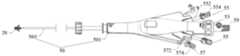
图3a为本申请中一实施方式提供的瓣膜夹与瓣膜输送装置的立体组装示意图;Fig. 3a is a three-dimensional assembly schematic diagram of a valve clip and a valve delivery device provided in an embodiment of the present application;
图3b为本申请中一实施方式提供的瓣膜输送装置的手柄的立体组装示意图;Fig. 3b is a three-dimensional assembly diagram of the handle of the valve delivery device provided in an embodiment of the present application;
图3c为本申请中一实施方式提供的瓣膜输送装置的手柄的立体分解示意图;Fig. 3c is a three-dimensional exploded schematic view of the handle of the valve delivery device provided in an embodiment of the present application;
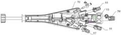
图3d为本申请中瓣膜输送装置的手柄去除上壳的立体示意图;Fig. 3d is a three-dimensional schematic diagram of removing the upper shell from the handle of the valve delivery device in the present application;
图3e为瓣膜输送装置在图3d基础上去除固定件、锁控固定件、密封件、与锁控密封件的立体示意图;Fig. 3e is a three-dimensional schematic diagram of removing the fixing part, the locking and controlling fixing part, the sealing part, and the locking and controlling sealing part of the valve delivery device on the basis of Fig. 3d;
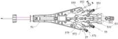
图3f为瓣膜输送装置在图3e基础上进一步去除下壳的立体示意图;Fig. 3f is a schematic perspective view of the valve delivery device further removing the lower shell on the basis of Fig. 3e;
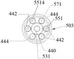
图4为本申请中一实施方式提供的瓣膜输送装置的导管的剖面示意图;Fig. 4 is a schematic cross-sectional view of a catheter of a valve delivery device provided in an embodiment of the present application;
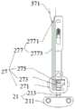
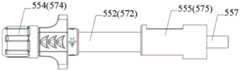
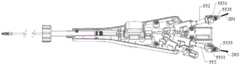
图5a为本申请中一实施方式提供的瓣膜输送装置的控制组件(锁控保险组件)的立体组装示意图;Fig. 5a is a three-dimensional assembly diagram of the control component (locking safety component) of the valve delivery device provided by an embodiment of the present application;
图5b为图5a所示的控制组件(锁控保险组件)沿轴向的剖面示意图;Fig. 5b is a schematic sectional view along the axial direction of the control assembly (lock control safety assembly) shown in Fig. 5a;
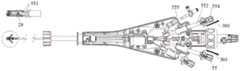
图5c为图5a所示的控制组件(锁控保险组件)的立体分解示意图;Fig. 5c is a three-dimensional exploded schematic view of the control assembly (locking safety assembly) shown in Fig. 5a;
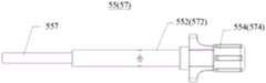
图6a为图5a所示的控制组件中控制杆的主视图;Figure 6a is a front view of the control rod in the control assembly shown in Figure 5a;
图6b为图6a所示的控制杆沿轴向的剖面示意图;Fig. 6b is a schematic cross-sectional view of the control rod shown in Fig. 6a along the axial direction;
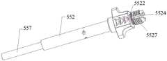
图6c为图6a所示的控制杆的另一视角的示意图;Fig. 6c is a schematic diagram of another viewing angle of the control rod shown in Fig. 6a;
图7a为控制组件中控制杆、管件、阻尼密封圈的立体组装示意图;Fig. 7a is a three-dimensional assembly diagram of a control rod, a pipe fitting, and a damping sealing ring in the control assembly;
图7b为控制组件中控制杆、密封件、管件、阻尼密封圈的立体组装示意图;Fig. 7b is a three-dimensional assembly schematic diagram of the control rod, the seal, the pipe fitting, and the damping sealing ring in the control assembly;
图7c为图7b所示的结构沿轴向的剖面示意图;Fig. 7c is a schematic cross-sectional view of the structure shown in Fig. 7b along the axial direction;
图7d为图7c的部分区域放大示意图;Fig. 7d is an enlarged schematic diagram of a part of Fig. 7c;
图8a、图8b、图8c、图8d为本申请一实施方式提供的密封件(锁控密封件)的不同视角的示意图;Fig. 8a, Fig. 8b, Fig. 8c, Fig. 8d are schematic diagrams of different viewing angles of the seal (lock control seal) provided by an embodiment of the present application;
图9a、图9b、图9c为本申请一实施方式提供的密封件的不同视角的示意图;Figure 9a, Figure 9b, and Figure 9c are schematic diagrams of different viewing angles of the seal provided by an embodiment of the present application;
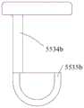
图10为本申请一实施方式提供的密封件的示意图;Fig. 10 is a schematic diagram of a seal provided in an embodiment of the present application;
图11为本申请一实施方式提供的密封件的示意图;Fig. 11 is a schematic diagram of a seal provided in an embodiment of the present application;
图12a为本申请一实施方式提供的控制组件(锁控保险组件)的部分结构示意图;Fig. 12a is a partial structural schematic diagram of a control component (lock control safety component) provided by an embodiment of the present application;
图12b为图12a所示的控制组件(锁控保险组件)的部分结构的分解示意图;Fig. 12b is an exploded schematic diagram of a partial structure of the control assembly (lock control safety assembly) shown in Fig. 12a;
图12c为控制组件(锁控保险组件)中的套筒(锁控套筒)的立体示意图;Fig. 12c is a three-dimensional schematic diagram of the sleeve (locking sleeve) in the control assembly (locking safety assembly);
图13a为控制组件中的管件与阻尼密封圈组装于一起的轴向剖面图;Figure 13a is an axial sectional view of the assembly of the pipe fittings and the damping sealing ring in the control assembly;
图13b为控制组件中的管件的主视图;Figure 13b is a front view of the pipe fittings in the control assembly;
图13c为图13b所示的管件的轴向剖面图;Figure 13c is an axial sectional view of the pipe fitting shown in Figure 13b;
图13d为控制组件中的阻尼密封圈的示意图;Figure 13d is a schematic diagram of the damping sealing ring in the control assembly;
图14为瓣膜夹输送装置的两控制组件使瓣膜夹的两个抓持元件相对靠拢的操作示意图;Figure 14 is a schematic diagram of the operation of the two control components of the valve clip delivery device to make the two grasping elements of the valve clip relatively close;
图15为瓣膜夹输送装置的两控制组件分别控制一抓持元件展开、另一抓持元件保持贴靠瓣膜夹的轴体的操作示意图。Fig. 15 is a schematic diagram of the operation of two control components of the valve clip delivery device respectively controlling the deployment of one gripping element and keeping the other gripping element against the shaft of the valve clip.
图16为移除瓣膜夹输送装置的控制组件中的固定件后的示意图;Fig. 16 is a schematic diagram after removing the fixing part in the control assembly of the valve clip delivery device;
图17为移除瓣膜夹输送装置的控制组件中的密封件后的示意图。Figure 17 is a schematic illustration of the valve clip delivery device with the seal removed from the control assembly.
具体实施方式Detailed ways
为了使本申请的目的、技术方案和优点更加清楚,下面将结合附图对本申请作进一步地详细描述。In order to make the purpose, technical solution and advantages of the application clearer, the application will be further described in detail below in conjunction with the accompanying drawings.
应当理解的是,可以在本申请中使用的诸如“包括”以及“可以包括”之类的表述表示所公开的功能、操作或构成要素的存在性,并且并不限制一个或多个附加功能、操作和构成要素。在本公开中,诸如“包括”和/或“具有”之类的术语可解释为表示特定特性、数目、操作、构成要素、组件或它们的组合,但是不可解释为将一个或多个其它特性、数目、操作、构成要素、组件或它们的组合的存在性或添加可能性排除在外。It should be understood that expressions such as "comprising" and "may include" that may be used in this application indicate the existence of disclosed functions, operations or constituent elements, and do not limit one or more additional functions, operation and components. In the present disclosure, terms such as "comprising" and/or "having" may be interpreted as indicating specific characteristics, numbers, operations, constituent elements, components, or combinations thereof, but shall not be interpreted as representing one or more other characteristics. , number, operation, constituent elements, components or the existence or possibility of addition of their combinations are excluded.
此外,在本申请中,表述“和/或”包括关联列出的词语中的任意和所有组合。例如,表述“A和/或B”可以包括A,可以包括B,或者可以包括A和B这二者。In addition, in this application, the expression "and/or" includes any and all combinations of the associated listed words. For example, the expression "A and/or B" may include A, may include B, or may include both A and B.
在本申请中,包含诸如“第一”和“第二”等的序数在内的表述可以修饰各要素。然而,这种要素不被上述表述限制。例如,上述表述并不限制要素的顺序和/或重要性。上述表述仅用于将一个要素与其它要素进行区分。类似地,在不脱离本公开的范围的情况下,第一要素可以被称为第二要素,类似地,第二要素也可以被称为第一要素。In the present application, expressions including ordinal numbers such as "first" and "second" may modify each element. However, such elements are not limited by the above expressions. For example, the above expressions do not limit the order and/or importance of elements. The above expressions are only used to distinguish one element from other elements. Similarly, a first element could be termed a second element, and, similarly, a second element could be termed a first element, without departing from the scope of the present disclosure.
当组件被称作“连接”或“接入”其他组件时,应当理解的是:该组件不仅直接连接到或接入到其他组件,而且在该组件和其它组件之间还可以存在另一组件。另一方面,当组件被称作“直接连接”或“直接接入”其他组件的情况下,应该理解它们之间不存在组件。When a component is referred to as being "connected" or "connected to" another component, it should be understood that the component is not only directly connected or connected to the other component, but there may also be another component between the component and the other component . On the other hand, when components are referred to as being "directly connected" or "directly connected to" other components, it should be understood that there is no component therebetween.
在介入医疗器械技术领域,一般将靠近操作者的方位定义为近端,远离操作者的方位定义为远端。将柱体、管体等一类物体的旋转中心轴的方向定义为轴向。径向是指垂直于或者大致垂直于轴向且沿柱体、管体的半径或直径延伸的方向。周向为围绕柱体、管体等一类物体的轴线的方向(垂直于轴线,同时垂直于半径)。In the field of interventional medical device technology, the orientation close to the operator is generally defined as the proximal end, and the orientation far away from the operator is defined as the distal end. The direction of the central axis of rotation of objects such as cylinders and tubes is defined as the axial direction. The radial direction refers to a direction perpendicular or approximately perpendicular to the axial direction and extending along the radius or diameter of the column or tube. The circumferential direction is the direction around the axis of objects such as cylinders and tubes (perpendicular to the axis and perpendicular to the radius).
请参阅图1,本申请一实施方式提供的瓣膜夹合系统100,用于对心脏瓣膜(图未示,可以是二尖瓣或三尖瓣)进行缘对缘修复。瓣膜夹合系统100包括瓣膜夹20、瓣膜夹输送装置50以及可调弯鞘60。瓣膜夹20可拆卸地连接于瓣膜夹输送装置50的远端,用于夹合瓣膜的至少两片瓣叶,以对瓣膜实施缘对缘修复。瓣膜夹输送装置50用于输送及控制瓣膜夹20。可调弯鞘60包括调弯手柄62及连接调弯手柄62并受调弯手柄62控制而发生相应弯曲的鞘管64。瓣膜夹输送装置50中的导管503(如图3a所示)活动穿设于鞘管64内,从而导管503的远端可以顺应鞘管64远端的弯曲而发生相应的弯曲,以顺应弯曲的介入路径。Please refer to FIG. 1 , a
请参阅图2a,瓣膜夹20包括基座21、可转动连接基座21的两驱动臂23及两个夹持元件25。两个驱动臂23与两个夹持元件25一一对应,每个夹持元件25与对应的一个驱动臂23转动连接,两个夹持元件25的第一端通过销轴(未标示)相互转动连接,两个夹持元件25的第二端均为自由端。基座21与瓣膜夹输送装置50的远端可拆卸连接。基座21、两个驱动臂23及两个夹持元件25组成连杆机构。基座21沿轴向运动能够使两个驱动臂23驱动两个夹持元件25呈辐射状展开或闭合,从而实现对瓣膜的夹持。Referring to FIG. 2 a , the
请结合参阅图2b,瓣膜夹20还包括自锁机构27,用于使瓣膜夹20在解锁状态及自锁状态之间进行切换。基座21包括座体211及凸设于座体211的轴体213。座体211的两侧分别与一夹持元件25转动连接。自锁机构27包括框体271、锁片273及弹压片275。框体271套设于轴体213外且框体271相对于两个夹持元件25第一端的轴向位置固定,锁片273与弹压片275收容于框体271内。锁片273套设于轴体213外,弹压片275设于框体271与锁片273之间,弹压片275用于偏压锁片273,使锁片273倾斜,锁片273上设有供轴体213穿过的通孔,当锁片273倾斜时,通孔抵持轴体213的部分侧壁,从而使轴体213不能沿轴向运动及沿周向旋转。Please refer to FIG. 2 b together, the
瓣膜夹20具有解锁状态及自锁状态,瓣膜夹20能够在解锁状态与自锁状态之间进行切换。当弹压片275偏压锁片273时,锁片273的通孔侧壁抵持基座21的轴体213,轴体213不能相对于锁片273做轴向运动,瓣膜夹20处于自锁状态。当锁片273受到外力作用而克服弹压片275的偏压时,锁片273回正,从而锁片273上供轴体213穿过的通孔不再抵持基座21的轴体213,轴体213能够相对于锁片273做轴向运动,瓣膜夹20即由自锁状态切换至解锁状态,此时瓣膜夹输送装置40控制轴体213轴向运动能够驱动两个夹持元件25呈辐射状展开或闭合。The
自锁机构27还包括连接件277,连接件277连接于锁片273与瓣膜输送装置50之间,用于在瓣膜输送装置50的驱动下带动锁片273克服弹压片275的偏压,使得瓣膜夹20由自锁状态切换至解锁状态。本实施方式中,连接件277大致呈U形,连接件277包括对折段2771及由对折段2771的两侧分别延伸出的两连接段2773。对折段2771与瓣膜输送装置50连接,连接段2773与锁片273连接。可以理解,连接件277不限定为U型,连接件277连接锁片273与瓣膜输送装置50即可。The self-locking
瓣膜夹20还包括两个抓持元件28,两个抓持元件28与两个夹持元件25一一对应,用于与夹持元件25配合夹持瓣叶。每个抓持元件28的一端相应靠近一夹持元件25的第一端,每个抓持元件28的另一端活动连接瓣膜夹输送装置50。抓持元件28具有弹性变形能力,在不受外力的作用下,两个抓持元件28呈辐射状展开。使用时,当瓣叶被定位在抓持元件28与夹持元件25之间后,瓣膜夹输送装置50控制夹持元件25闭合,抓持元件28配合夹持元件25起到捕获瓣叶、定位瓣叶的作用。抓持元件28上还可以设有倒刺,用于将瓣叶压入夹持元件25的内表面,提高对瓣叶的锚定及保持作用。The
可以理解,在其他实施例中,夹持元件25的数量可以为两个以上,驱动臂23的数量可以为两个以上,保证瓣膜夹20能够实现夹持或松开瓣叶,以及自锁或解锁即可。It can be understood that, in other embodiments, the number of clamping
请参阅图3a,瓣膜夹输送装置50还包括与导管503连接的手柄501。手柄501用于方便操作者握持及控制瓣膜夹20。导管503的近端固定连接于手柄501的远端,导管503的远端延伸至瓣膜夹20。Please refer to FIG. 3 a , the valve
请结合参阅图3b、图3c及图3d,手柄501包括壳体51、夹控组件53、两个控制组件55及锁控保险组件57。夹控组件53、两个控制组件55及锁控保险组件57均设于壳体51上。夹控组件53用于控制两个夹持元件25在瓣膜夹20处于解锁状态时相对打开或闭合。一控制组件55对应控制一抓持元件28。两个控制组件55分别位于壳体51及导管503(例如导管503的中轴线)的相对两侧,用于控制相应侧的抓持元件28并方便区分。锁控保险组件57用于控制瓣膜夹20于解锁状态及自锁状态之间进行切换。Please refer to FIG. 3 b , FIG. 3 c and FIG. 3 d in conjunction, the
可以理解,本申请不限定抓持元件28的数量、控制组件55的数量,在其他实施例中,抓持元件28的数量可以为两个以上,控制组件55的数量可以为两个以上,每个控制组件55对应控制一个抓持元件28。It can be understood that the present application does not limit the number of
请参阅图3e及图3f,夹控组件53包括芯轴531及传动件532。芯轴531的远端与瓣膜夹20的轴体213(如图2a所示)的近端可拆卸连接。本实施方式中,芯轴531的远端与轴体213的近端螺纹连接。芯轴531的近端活动穿过导管503并与传动件532连接。传动件532可在壳体51内沿轴向滑动,以带动芯轴531轴向运动,从而驱动两夹持元件25相对打开或闭合。请参阅图4,导管503内还设置中心腔440,芯轴531活动穿设于中心腔440内。Please refer to FIG. 3e and FIG. 3f , the clamping
本申请的一些实施方式中,控制组件55及锁控保险组件57的结构大致相同,为节省篇幅,以下以控制组件55为例作较为详细地描述。In some embodiments of the present application, the structures of the
请结合参阅图3f、图5a、图5b与图5c,每一控制组件55均包括控制丝551、控制杆552、密封件553及固定件554。控制杆552活动穿设于壳体51内。控制杆552具有沿轴向延伸的内腔5521(如图6a所示)。控制丝551活动穿过内腔5521,控制丝551的近端部分绕设于控制杆552的近端上。控制丝551对应连接控制杆552及抓持元件28。控制丝551的位于控制杆552及抓持元件28之间的部分活动穿设于导管503内。密封件553可拆卸地配合在控制杆552上并压紧控制丝551在控制杆552上绕设的部分,从而固定控制丝551的近端部分。Please refer to FIG. 3 f , FIG. 5 a , FIG. 5 b and FIG. 5 c in conjunction, each
请再次参阅图2a,每一控制丝551均呈U形,包括对折段5513及自对折段5513的两侧分别延伸出的两连接段5514。请再次参阅图4,导管503内设置四个第一分腔442,一连接段5514的近端对应活动穿过一第一分腔442并绕设至相应的控制杆552上,对折段5513活动地连接抓持元件28。Please refer to FIG. 2 a again, each
控制丝551采用U形方式,按照一腔一股丝的方式布置,能够防止控制丝551的两股连接段5514相互缠绕,从而在撤出控制丝551时更为顺畅、轻松,避免出现扯线、断线的风险,提高安全性。The
控制杆552的行程应不小于2πR×θ/360,其中,所述R为抓持元件28的长度,所述θ为第一角度与第二角度之间的差值的绝对值,所述第一角度为抓持元件28在相对靠拢时,抓持元件28与瓣膜夹20的中轴线(轴体213的中轴线)之间的角度,所述第二角度为抓持元件28在呈辐射状展开后,抓持元件28与瓣膜夹20的中轴线之间的最大角度。在抓持元件28在相对靠拢(或称被释放前)时,抓持元件28与瓣膜夹20的中轴线之间的第一角度可以为0度;在抓持元件28在呈辐射状展开后(或称被释放后),抓持元件28与瓣膜夹20的中轴线之间的第二角度,可以小于90度,等于90度或大于90度。The stroke of the
考虑到控制丝551在第一分腔442内的损耗,控制杆552的有效推进行程优选设置为2×(2πR×θ/360)。例如,抓持元件28自相对靠拢运动至相对展开后,抓持元件28与控制丝551连接的一端对应划过的周长为13mm,则控制杆552的有效行程优选25±2mm,一方面在收紧抓持元件28时,不会将控制丝551拉断或损坏,另一方面在释放抓持元件28时,控制丝551不会堆叠的太多。Considering the loss of the
请参阅图6a、图6b及图6c,控制杆552的近端设有周向卡槽5522,用于安装密封件553及绕设控制丝551。控制丝551穿过内腔5521后绕设在周向卡槽5522上。控制杆552还设有与内腔5521连通的容置槽5524,用于容置至少部分密封件553。容置槽5524贯通控制杆552的近端面及控制杆552近端的周向外壁。控制杆552近端的周向外壁上设有外螺纹5527,用于与固定件554可拆卸连接。本实施方式中,容置槽5524始于周向卡槽5522的近端、沿轴向延伸至控制杆552的近端面。控制杆552的材质包括但不限定为三元共聚物ABS与聚苯乙烯(po lystyrene,PS),三元共聚物ABS为丙烯腈(A)、丁二烯(B)、苯乙烯(S)三种单体的共聚物。控制杆552可以为模具注塑成型,保证其内腔光滑,以及内径尺寸的一致性。Referring to FIG. 6 a , FIG. 6 b and FIG. 6 c , the proximal end of the
请结合参阅图5b、图7a、图7b、图7c、图7d及图8a,密封件553包括密封圈5531及连接于密封圈5531的操作结构5533,密封圈5531部分收容于周向卡槽5522内并与周向卡槽5522过盈配合,密封圈5531压紧控制丝551在周向卡槽5522内的绕设部分。控制丝551可被压紧在密封圈5531朝向轴线的内壁与周向卡槽5522的底壁之间,或者,控制丝551也可被压紧在密封圈5531的端面与周向卡槽5522的槽壁之间。本申请的一些实施方式中,密封圈5531的径向截面的形状为矩形,以增大密封圈5531与控制丝551的接触面积,从而保证对控制丝551实施可靠、足够的压紧。在其他实施方式中,密封圈5531的径向截面的形状可以为圆形或其他形状,本申请对此不作限定。密封件553的材质包括但不限定为硅胶或橡胶。Please refer to Fig. 5b, Fig. 7a, Fig. 7b, Fig. 7c, Fig. 7d and Fig. 8a, the sealing
具体的,固定件554上设有轴向孔5541,控制杆552至少部分可穿设于轴向孔5541内并与固定件554可拆卸连接。固定件554连接控制杆552时,固定件554挤压密封圈5531,且操作结构5533亦被收容于轴向孔5541内。本实施方式中,控制杆552上设有外螺纹5527,轴向孔5541的孔壁上设有内螺纹5543,外螺纹5527与内螺纹5543适配螺接。Specifically, the fixing
控制丝551的两个连接段5514(如图2a所示)远离对折段5513的自由端经由容置槽5524穿出并绕在控制杆552的周向卡槽5522(如图7d所示)内,固定件554挤压密封圈5531并旋紧在控制杆552上,以对控制丝551的连接段5514远离对折段5513的自由端进行挤压固定。The free ends of the two connecting
操作结构5533包括固接部5534与操作部5535。固接部5534的第一端与密封圈5531固定连接。固接部5534的第二端与操作部5535固定连接。固接部5534可被容置于容置槽5524内,避免固定件554内的内螺纹与控制杆552上的外螺纹5527螺接时,固接部5534受到螺纹的绞扭而损伤,保证操作部5535与密封圈5531之间的连接可靠性,操作者手持操作部5535经固接部5534向密封圈5531施加向近端的轴向力,能够分离密封圈5531与控制杆552。The
请结合参阅图8a至图8d,本实施方式中,固接部5534的第一端与密封圈5531的靠近密封圈5531的轴线的内壁固定连接,以增大固接部5534与密封圈5531的连接面积,提高连接可靠性。固接部5534沿密封圈5531的轴向延伸。固接部5534的任意部位均位于密封圈5531的外壁的内侧(从径向方向看,靠近密封圈5531中轴线的一侧为内,远离密封圈5531中轴线的一侧为外),进一步地,优选固接部5534的任意部位均位于密封圈5531的内壁的内侧或固接部5534的任意部位的最外侧点平齐于密封圈5531的内壁,以使得固接部5534的任意部位相对远离密封圈5531的外壁,这样设置的好处是,固接部5534能够避开固定件554内的内螺纹与控制杆552上的外螺纹5527,从而避免内外螺纹螺接时绞扭、损伤固接部5534,保证固接部5534的完整性以及保证操作部5535与密封圈5531之间的连接可靠,操作者手持操作部5535经固接部5534向密封圈5531施加向近端的轴向力,能够分离密封圈5531与控制杆552。Please refer to FIGS. 8a to 8d in conjunction. In this embodiment, the first end of the fixed
本实施方式中,固接部5534的数量为两个,两个固接部5534位于密封圈5531的同一直径上。在其他实施方式中,固接部5534也可以固定于密封圈5531的近端面上,且固接部5534的任意部位均位于密封圈5531的外壁的内侧。In this embodiment, there are two affixed
操作部5535的近端至少部分露出控制杆552的近端。操作部5535供操作者手持操作,以使密封圈5531脱离与之配合的控制杆552。所述手持操作包括但不限于握持、拉拽、捏持中的至少一种。操作部5535优选为具有一定厚度的片状实体,以方便操作者握持施力。The proximal end of the
一方面,操作者需取下密封件553时,无需像现有技术那样使用镊子、钳子等辅助工具夹持密封圈5531,而可以直接手持操作部5535向近端拉拽,快捷地将密封圈5531及整个密封件553从控制杆552上移除,这样一来,显著简化了手术操作步骤、节省了操作时间及降低了操作难度。On the one hand, when the operator needs to remove the sealing
另一方面,将控制丝551组装于控制杆552上时,控制丝551的近端部分从控制杆552的内腔5521穿出至容置槽5524外,将控制丝551的近端部分缠绕在控制杆552上的周向卡槽5522中,再将密封件553的密封圈5531套设在周向卡槽5522上,通过密封圈5531预压紧控制丝551,再将固定件554与控制杆552螺接,固定件554可以在轴向和/或径向上将密封圈5531压紧,以将控制丝551牢靠地固定在控制杆552上,实现密封圈5531对控制丝551的绕设部分的固定,方便组装。On the other hand, when the
本实施方式中,控制丝551选用具有弹性及形状记忆性能的镍钛材质,以降低断丝的风险。在操作者取下密封圈5531时,镍钛材质的控制丝551脱离了密封圈5531的束缚,即自动弹开回直,方便操作者撤出控制丝551,以解脱瓣膜夹20。可以理解,本申请对控制丝551的材质不作限定,例如,控制丝551还可以采用超高分子聚乙烯缝合线、不锈钢丝、高分子聚合物线中的一种。In this embodiment, the
在固定件554旋紧的情况下,通过向近端后拉控制杆552,控制丝551便可以提拉抓持元件28,使得抓持元件28与夹持元件25之间形成瓣叶容纳空间。通过向远端推送控制杆552,控制丝551放松,抓持元件28在自身弹性作用下,抓持元件28与控制丝551连接的一端向夹持元件25贴靠,从而抓捕到瓣叶;在固定件554卸除的情况下,通过手持操作部5535直接取下密封圈5531及密封件553,控制丝551脱离密封圈5531的束缚而自动弹开回直,抽拉控制丝551其中一连接段5514的自由端,便可将控制丝551移除体外,以不妨碍后续瓣膜夹20的解脱。When the fixing
在其他实施方式中,可以省略周向卡槽5522,而将控制丝551的近端部分直接绕设在控制杆552的杆体上;在其他实施方式中,也可以省略容置槽5524,同时设置固接部5534固定于密封圈5531的近端面上,且固接部5534的任意部位均位于密封圈5531的外壁的内侧。In other embodiments, the
本申请对操作结构的结构不作限定,如图9a与图9b所示,操作部5535a可为具有镂空的弧状体;在其他一些实施方式中,操作部5535a可为具有镂空的环状体。在一些实施方式中,如图10所示,固接部5534b的数量可以为一个,操作部5535b仍可为实体片状结构。在一些实施方式中,如图11所示,操作结构5533c包括至少一个封闭线圈,封闭线圈活动串接地穿过密封圈5531c并与密封圈5531c套接;操作部5535c位于封闭线圈远离密封圈5531c的端部。The present application does not limit the structure of the operating structure. As shown in FIG. 9a and FIG. 9b, the operating
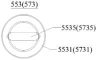
请参阅图12a、图12b、图12c及图3e,控制组件55还包括套筒555,套筒555固定收容于壳体51内。套筒555固定于壳体51内的固定方式可选择卡合、粘接、螺接等,在此不作限定。控制杆552可活动穿设于套筒555内。控制杆552的外壁上设有第一导向部5528,套筒555的内壁设有第二导向部5552,第一导向部5528与第二导向部5552用于对控制杆552相对壳体51的轴向运动进行导向,提高控制杆552相对壳体51的轴向运动的顺畅性。Please refer to FIG. 12 a , FIG. 12 b , FIG. 12 c and FIG. 3 e , the
本实施方式中,第一导向部5528为导向凸块,第二导向部5552为设于套筒555的内壁的导向凹槽,套筒555的近端还设有与导向凹槽连通的限位槽5554,限位槽5554沿套筒555的周向延伸并具限位台阶5557,限位槽5554大致为弧形槽。控制杆552的导向凸块抵接限位槽5554的底面时,控制杆552不能相对套筒555向远端移动。限位槽5554的起始端面与第二导向部5552的一壁面平齐,限位台阶5557位于限位槽5554的终止端面5559与第二导向部5552的另一壁面之间。限位台阶5557用于将第一导向部5528限制于限位槽5554内,防止第一导向部5528脱离限位槽5554。第一导向部5528收容于限位槽5554内并与限位台阶559相抵持时,控制丝551呈拉直状态,控制丝551提拉抓持元件28。In this embodiment, the
可以理解,第一导向部5528与第二导向部5552中的其中一个为沿控制杆552的轴向延伸的导向凹槽,另一个为导向凸块,所述导向凸块滑动穿设于所述导向凹槽内。可以理解,套筒555可以省略,控制杆552能够相对壳体51进行轴向运动即可。It can be understood that one of the
请结合参阅图5b、图5c、图13a、图13b及图13c,控制组件55还包括管件557与阻尼密封圈558。管件557固定于壳体51上。管件557具有轴向延伸的管腔5571。控制杆552的内腔5521可滑动地套设于管件557上。控制丝551活动穿过管件557的管腔5571及控制杆552的内腔5521。阻尼密封圈558大致为O型密封圈,阻尼密封圈558套设在管件557上。阻尼密封圈558被夹设于管件557的外壁与控制杆552的内腔5521之间,且阻尼密封圈558与控制杆552的内腔5521过盈配合。管件557的外壁上环设有周向凹槽5573,阻尼密封圈558至少部分收容于周向凹槽5573内,阻尼密封圈558的内径小于周向凹槽5573的内径。本实施方式中,阻尼密封圈558的材质包括但不限定硅胶或橡胶。管件557的外壁上设置有两组周向凹槽5573,阻尼密封圈558的数量为两个。每个阻尼密封圈558安装在对应的一个周向凹槽5573内。Please refer to FIG. 5 b , FIG. 5 c , FIG. 13 a , FIG. 13 b and FIG. 13 c together, the
阻尼密封圈558与控制杆552的内腔5521的内壁过盈配合,控制杆552的内腔5521的内壁挤压阻尼密封圈558从而在二者之间产生摩擦阻力,通过过盈量的控制可设置该摩擦阻力等于抓持元件28收紧至预定位置时对控制丝551所产生的最大力值。操作者沿轴向前推或者后拉控制杆552时,操作者所施加的外力大于所述内腔5521的内壁与阻尼密封圈558之间的摩擦阻力。而一旦操作者停止施力,由于摩擦阻力大于除收紧位置时任意位置的抓持元件28对控制丝551产生的力,所以抓持元件28可在任意位置驻停,即保持任意张开角度。阻尼密封圈558还能够提供过载保护,假若控制杆552通过控制丝551将抓持元件28收得过紧,那么松手后,在阻尼密封圈558的作用下,控制丝551会带动控制杆552自动向施力大的抓持元件28的一侧移动,直至摩擦阻力与预定收紧位置的抓持元件28对控制丝551施加的力达到平衡,从而不会因抓持元件28收得过紧而损伤瓣膜夹20。The damping
通过操作控制杆552可实现控制抓持元件28运动,以配合夹持元件25捕捉或松开瓣叶。两个控制组件55可同时被操控,例如,可同步操作两个控制组件55的控制杆552由近端向远端运动,两个控制丝551呈松弛状态,抓持元件28在自身弹性作用下,抓持元件28与控制丝551连接的一端向夹持元件25贴靠,方便配合夹持元件25抓捕到瓣叶。又如,请参阅图14,同步操作两个控制组件55的控制杆552由远端向近端(例如图14中箭头301与箭头303所指方向)运动,使每个控制丝551提拉对应的抓持元件28向瓣膜夹20的中轴线靠拢,从而使抓持元件28与相应的夹持元件25之间形成容纳瓣叶的容纳空间(图未示),瓣叶可进入该容纳空间内。也可单独控制单边的抓持元件28去抓捕处于动态的前叶或后叶,抓捕单边瓣叶成功并调整角度后,再控制另一个抓持元件28抓捕另一边的处于动态的后叶或前叶,从而能够降低抓捕瓣叶的难度、提高抓捕效率及手术的成功率,例如,请参阅图15,一个控制组件55的控制杆552由近端向远端(例如图15中箭头305所指方向)运动,另一个控制组件55的控制杆552由远端向近端(例如图15中箭头307所指方向)运动。The movement of the
请参阅图16与图17,释放瓣膜夹20前需撤出控制丝551时,将固定件554旋松卸下,此时密封件553的操作部5535露出,操作者用手捏住操作部5535向近端拉拽(如图16所示的箭头201与箭头203所指方向),将密封圈5531及整个密封件553移除;缠绕在控制杆552上的控制丝551失去密封圈5531的束缚立即弹出,即解除了密封圈5531对控制丝551的固定。可见,通过在密封件553上设置易于手持操作的操作部5533,操作者可以快速取下密封圈5531,解除对控制丝551的固定,显著提高了操作便捷度。如图17所示,将控制丝551的一端由近端向远端后拉(如箭头207所指方向),即可撤出控制丝551。Please refer to Figure 16 and Figure 17, when the
密封件553不限定应用于控制组件55中,密封件553也可以与其他部件配合连接。本申请还提供一种密封组件,密封组件包括配合件及密封件553,密封件553包括密封圈5531及连接于密封圈5531的操作结构5533,操作结构5533包括操作部5535;操作部5535供操作者手持操作。密封圈5531过盈配合在配合件上;通过手持操作操作部5535,能够使密封件553快捷脱离配合件。The
请结合参阅图3f、图5a、图5b及图5c,锁控保险组件57包括锁控丝571、锁控杆572及锁控密封件573。锁控杆572活动穿设于壳体51上,锁控丝571活动连接自锁结构27及锁控密封件573。锁控丝572的结构与控制丝551大致相同,锁控丝572呈U形,锁控丝572包括对折段及自对折段的两侧分别延伸出的两连接段。请参阅图4,导管503内设置两个第二分腔444,锁控丝572的一个连接段的近端对应活动穿过一第二分腔444并连接至锁控杆572的近端。锁控丝572的对折段自连接件277的对折段2771穿过,实现锁控丝571活动地连接自锁机构27。Please refer to FIG. 3 f , FIG. 5 a , FIG. 5 b and FIG. 5 c together, the lock
结合图8a至图8d,锁控密封件573包括锁控密封圈5731及连接于锁控密封圈5731的锁控操作结构5733。锁控操作结构5733包括锁控操作部5735。锁控丝571的近端部分绕设于锁控杆572上。锁控密封圈5731过盈配合在锁控杆572上并压紧锁控丝571的绕设部分。通过手持操作锁控操作部5735,能够使锁控密封件573快捷脱离锁控杆572。锁控丝571连接锁控杆572及自锁机构27(如图2a与图2b所示)。锁控丝571的位于锁控杆572及自锁机构27之间的部分活动穿设于导管503内。锁控杆572带动锁控丝571相对壳体51由远端向近端方向的运动使得瓣膜夹20由所述自锁状态切换至所述解锁状态。Referring to FIG. 8a to FIG. 8d , the
锁控保险组件57还可以包括锁控固定件574。锁控固定件574上设有轴向孔5741,锁控固定件574至少部分可穿设于轴向孔5741内并与锁控固定件574可拆卸连接。锁控固定件574连接锁控杆572时,锁控固定件574挤压锁控密封圈5731,且锁控操作结构5733亦被收容于轴向孔5741内。The lock
瓣膜夹合系统100中的锁控保险组件57能够确保瓣膜夹20在自锁状态下输送到位,只有通过锁控保险组件57控制瓣膜夹20切换至解锁状态后,才能打开瓣膜夹20的夹持元件25以夹持瓣叶,从而能够避免瓣膜夹20在输送过程中被意外打开,有助于瓣膜缘对缘修复术的顺利进行,保障手术的安全性。此外,瓣膜夹20只有在打开、关闭以夹持住瓣叶之后,解脱瓣膜夹20的动作才能执行,因此锁控保险组件57的设置实际上也降低了瓣膜夹20意外解脱的风险。The locking
请结合参阅图12a、图12b与图12c,锁控保险组件57还可以包括锁控套筒575,锁控杆572的外壁上设有第一导向部5728,锁控套筒575的内壁设有第二导向部5752,第一导向部5728与第二导向部5752用于对锁控杆572相对壳体51的轴向运动进行导向,提高锁控杆572相对壳体51的轴向运动的顺畅性。第一导向部5728与第二导向部5752可滑动连接。Please refer to Fig. 12a, Fig. 12b and Fig. 12c in conjunction, the lock
对于锁控丝571的材质、锁控杆572的具体结构、锁控密封件573的具体结构、锁控套筒575的具体结构、锁控固定件574的具体结构、以及锁控保险组件57各元件之间的相互配合关系,可以参考上述控制组件55的描述,在此不作赘述。For the material of the
在锁控固定件574旋紧的情况下,通过向近端后拉锁控杆572,锁控丝571便可以提拉锁片273向水平状回正,从而解除对轴体213的锁定。相应的,通过向远端推送锁控杆572,锁控丝571放松,锁片273在弹压片275的作用下倾斜,使得瓣膜夹20处于自锁状态;在锁控固定件574卸除、锁控密封件573移除的情况下,抽拉锁控丝571,便可将锁控丝571撤出体外,以不妨碍后续瓣膜夹20的解脱。When the
通过操作锁控杆572来驱动锁控丝571可实现瓣膜夹20于自锁状态和解锁状态之间进行切换。瓣膜夹20由解锁状态切换至自锁状态所需的操作为:旋转锁控杆572使锁控杆572的第一导向部5728,使第一导向部5728在锁控套筒575的限位槽5754内运动以逐渐远离限位槽5754的终止端面5759,第一导向部5728脱离限位槽5754并进入锁控套筒575的第二导向部5752,驱动锁控杆572向远端运动,锁控丝571呈松弛状态,自锁机构27自锁,瓣膜夹20切换至自锁状态。The
当瓣膜夹20需从自锁状态切换至解锁状态时,驱动锁控杆572向近端运动,锁控丝571呈拉直状态并提拉自锁机构27,使自锁机构27与瓣膜夹20解锁。之后,旋转锁控杆572,使锁控杆572的第一导向部5728进入锁控套筒575的限位槽5754并朝向限位槽5754的终止端面5759所在方向运动,直至锁控杆572的第一导向部5728与锁控套筒575的限位台阶5757相抵持,锁控杆572一直提拉锁控丝571使瓣膜夹20保持解锁状态,允许瓣膜夹20打开或闭合。When the
请再次参阅图3a、图3b、图3c及图3d,瓣膜夹输送装置501还包括与芯轴531连接的解脱控制组件59,用于在瓣膜夹20夹持固定二尖瓣的前叶与后叶,完成双孔治疗后,使得瓣膜夹20与芯轴531解脱。Please refer to Fig. 3a, Fig. 3b, Fig. 3c and Fig. 3d again, the valve
以下对瓣膜夹合系统100的工作过程作简单描述:The following is a brief description of the working process of the valve clamping system 100:
瓣膜夹20通过瓣膜输送装置50以经导管的方式输送至患者的二尖瓣附近。The
初始状态下,锁控杆572处于前推的状态使得瓣膜夹20保持自锁状态,两控制杆552均被向近端后拉并限位,使得两个抓持元件28处于相对靠拢状态。操作者通过调弯手柄62调整鞘管64的弯曲程度,穿设在鞘管64内的导管503顺应鞘管64,输送瓣膜夹20到达患者的二尖瓣附近的预定位点。In the initial state, the
驱动锁控杆572向近端移动,瓣膜夹20由自锁状态切换至解锁状态,即通过锁控保险组件57解除瓣膜夹20的自锁。将锁控杆572的第一导向部收容于锁控套筒575的限位槽5754内并与限位台阶5757相抵持,使瓣膜夹20保持解锁状态。Drive the locking
然后,通过夹控组件53控制瓣膜夹20的夹持元件25张开。Then, the clamping
再通过控制组件55控制抓持元件28将瓣叶捕获在夹持元件25与抓持元件28之间,可以先向远端前推一控制杆552,捕获一瓣叶;再向远端前推另一控制杆552,捕获另一瓣叶。Then control the grasping
接着,通过夹控组件53控制两个夹持元件25闭合,将二尖瓣的前叶和后叶夹合在一起,使得两个夹持元件25闭合,以夹合瓣叶。Next, the two clamping
一旦二尖瓣的瓣叶被缘对缘地对合在一起,将锁控固定件574卸下,移除锁控密封件573,将锁控丝571撤出体外;再将固定件554卸下,移除固定件554,移除密封件553,并将控制丝551撤出体外。Once the valve leaflets of the mitral valve are joined together edge-to-edge, the
最后,将瓣膜夹输送装置50撤出体外,使瓣膜夹20保留在瓣膜处,实现二尖瓣的“缘对缘修复”。Finally, the valve
可以理解的是,本申请的瓣膜夹合系统100也可以以经导管的方式对三尖瓣实施缘对缘修复。It can be understood that the
以上,仅是本申请的较佳实施方式而已,并非对本申请作任何形式上的限制。虽然本申请已以较佳实施方式揭露如上,然而并非用以限定本申请。任何熟悉本领域的技术人员,在不脱离本申请技术方案范围情况下,都可利用上述揭示的方法和技术内容对本申请技术方案做出许多可能的变动和修饰,或修改为等同变化的等效实施方式。因此,凡是未脱离本申请技术方案的内容,依据本申请的技术实质对以上实施方式所做的任何简单修改、等同变化及修饰,均仍属于本申请技术方案保护的范围内。The above are only preferred implementation modes of the present application, and do not limit the present application in any form. Although the present application has disclosed the above with preferred implementation modes, it is not intended to limit the present application. Any person familiar with the art, without departing from the scope of the technical solution of the application, can use the methods and technical content disclosed above to make many possible changes and modifications to the technical solution of the application, or modify the equivalent of equivalent changes implementation. Therefore, any simple modifications, equivalent changes and modifications made to the above implementation methods based on the technical essence of the present application that do not deviate from the content of the technical solution of the present application still fall within the protection scope of the technical solution of the present application.
Claims (20)
Translated fromChinesePriority Applications (2)
| Application Number | Priority Date | Filing Date | Title |
|---|---|---|---|
| CN202111633714.2ACN116350394A (en) | 2021-12-28 | 2021-12-28 | Seal, seal assembly, control assembly, and valve clip delivery device |
| PCT/CN2022/136374WO2023124786A1 (en) | 2021-12-28 | 2022-12-02 | Sealing member, sealing assembly, control assembly and valve clip delivery device |
Applications Claiming Priority (1)
| Application Number | Priority Date | Filing Date | Title |
|---|---|---|---|
| CN202111633714.2ACN116350394A (en) | 2021-12-28 | 2021-12-28 | Seal, seal assembly, control assembly, and valve clip delivery device |
Publications (1)
| Publication Number | Publication Date |
|---|---|
| CN116350394Atrue CN116350394A (en) | 2023-06-30 |
Family
ID=86926187
Family Applications (1)
| Application Number | Title | Priority Date | Filing Date |
|---|---|---|---|
| CN202111633714.2APendingCN116350394A (en) | 2021-12-28 | 2021-12-28 | Seal, seal assembly, control assembly, and valve clip delivery device |
Country Status (2)
| Country | Link |
|---|---|
| CN (1) | CN116350394A (en) |
| WO (1) | WO2023124786A1 (en) |
Citations (5)
| Publication number | Priority date | Publication date | Assignee | Title |
|---|---|---|---|---|
| CN205434007U (en)* | 2015-12-31 | 2016-08-10 | 江苏常美医疗器械有限公司 | Take bone cement filled ware of O type circle |
| CN108464945A (en)* | 2018-05-03 | 2018-08-31 | 杭州糖吉医疗科技有限公司 | Jejunum casing release system and its application method built in a kind of duodenum |
| CN110916852A (en)* | 2019-12-12 | 2020-03-27 | 上海纽脉医疗科技有限公司 | Outer tube moving mechanism and valve conveying device |
| CN111200995A (en)* | 2017-09-07 | 2020-05-26 | 爱德华兹生命科学公司 | Prosthetic spacer device for heart valves |
| US20210315565A1 (en)* | 2018-12-26 | 2021-10-14 | Hangzhou Valgen Medtech Co., Ltd. | Locking device with locking feedback function and heart valve repair system |
Family Cites Families (7)
| Publication number | Priority date | Publication date | Assignee | Title |
|---|---|---|---|---|
| US4244478A (en)* | 1979-06-27 | 1981-01-13 | Mpl, Inc. | Closure assembly for unit dose vial |
| EP2393531B1 (en)* | 2009-02-06 | 2021-03-31 | Becton, Dickinson and Company | Pen needle to facilitate manipulation by users having physical or visual impairment |
| CN105114086A (en)* | 2015-08-28 | 2015-12-02 | 重庆市腾瀚工贸有限公司 | Hob mounting structure of shield tunneling machine |
| JP7543391B2 (en)* | 2019-07-15 | 2024-09-02 | エバルブ,インコーポレイティド | Method of Actuating Individual Proximal Elements |
| CN112274297B (en)* | 2019-07-24 | 2025-08-01 | 上海形状记忆合金材料有限公司 | Transcatheter heart valve clamping system |
| CN111789699B (en)* | 2019-11-19 | 2024-12-20 | 杭州德晋医疗科技有限公司 | Independently controlled valve clamping system |
| JP2023514193A (en)* | 2020-02-11 | 2023-04-05 | エンボディ,インコーポレイテッド | Surgical cannula with removable pressure seal |
- 2021
- 2021-12-28CNCN202111633714.2Apatent/CN116350394A/enactivePending
- 2022
- 2022-12-02WOPCT/CN2022/136374patent/WO2023124786A1/ennot_activeCeased
Patent Citations (5)
| Publication number | Priority date | Publication date | Assignee | Title |
|---|---|---|---|---|
| CN205434007U (en)* | 2015-12-31 | 2016-08-10 | 江苏常美医疗器械有限公司 | Take bone cement filled ware of O type circle |
| CN111200995A (en)* | 2017-09-07 | 2020-05-26 | 爱德华兹生命科学公司 | Prosthetic spacer device for heart valves |
| CN108464945A (en)* | 2018-05-03 | 2018-08-31 | 杭州糖吉医疗科技有限公司 | Jejunum casing release system and its application method built in a kind of duodenum |
| US20210315565A1 (en)* | 2018-12-26 | 2021-10-14 | Hangzhou Valgen Medtech Co., Ltd. | Locking device with locking feedback function and heart valve repair system |
| CN110916852A (en)* | 2019-12-12 | 2020-03-27 | 上海纽脉医疗科技有限公司 | Outer tube moving mechanism and valve conveying device |
Also Published As
| Publication number | Publication date |
|---|---|
| WO2023124786A1 (en) | 2023-07-06 |
Similar Documents
| Publication | Publication Date | Title |
|---|---|---|
| US20220142781A1 (en) | Valve clamping system capable of being independently controlled | |
| WO2022121527A1 (en) | Valve clip delivery device | |
| CN111920549A (en) | Clip body of mitral valve clamping device, mitral valve clamping device and repair equipment | |
| CN114617673A (en) | Valve clip delivery device | |
| CN114431917B (en) | Hemostatic clamp | |
| CN114680966B (en) | Medical locking device with controllable traction force | |
| US12083014B2 (en) | Fixing device for clamping tissue | |
| CN114176839B (en) | Valve clamp and valve repair system | |
| CN115429488B (en) | Valve clamping system | |
| CN115281895A (en) | Valve clip control handle, delivery device and valve repair system | |
| WO2023173967A1 (en) | Valve repair system and coupling instrument thereof | |
| CN215778919U (en) | Valve clip delivery device | |
| CN215273015U (en) | Clamping self-locking assembly of tissue fixing device | |
| CN114681143A (en) | An adaptive valve clamping device and valve clamping system | |
| CN114569288B (en) | Valve clamp and valve repair system | |
| CN115281894A (en) | Valve clip control handle, delivery device and valve repair system | |
| CN115281892A (en) | Valve clip control handle, delivery device and valve repair system | |
| CN116350394A (en) | Seal, seal assembly, control assembly, and valve clip delivery device | |
| CN212346606U (en) | Pulling force driving type locking device | |
| CN219147693U (en) | Implant delivery system | |
| CN114948339A (en) | Convenient valve clip delivery device | |
| CN214805716U (en) | A delivery device for tethered artificial valve | |
| CN214595939U (en) | Hemostatic clamp | |
| CN211243518U (en) | Intervention type remote suture locking device | |
| CN113116426B (en) | Direct-drive suture knot locking device |
Legal Events
| Date | Code | Title | Description |
|---|---|---|---|
| PB01 | Publication | ||
| PB01 | Publication | ||
| SE01 | Entry into force of request for substantive examination | ||
| SE01 | Entry into force of request for substantive examination |