CN116350393A - Valve clamp and valve clamp system - Google Patents
Valve clamp and valve clamp systemDownload PDFInfo
- Publication number
- CN116350393A CN116350393ACN202111627769.2ACN202111627769ACN116350393ACN 116350393 ACN116350393 ACN 116350393ACN 202111627769 ACN202111627769 ACN 202111627769ACN 116350393 ACN116350393 ACN 116350393A
- Authority
- CN
- China
- Prior art keywords
- valve
- fixed base
- clamp
- clip
- control
- Prior art date
- Legal status (The legal status is an assumption and is not a legal conclusion. Google has not performed a legal analysis and makes no representation as to the accuracy of the status listed.)
- Pending
Links
Images


Classifications
- A—HUMAN NECESSITIES
- A61—MEDICAL OR VETERINARY SCIENCE; HYGIENE
- A61F—FILTERS IMPLANTABLE INTO BLOOD VESSELS; PROSTHESES; DEVICES PROVIDING PATENCY TO, OR PREVENTING COLLAPSING OF, TUBULAR STRUCTURES OF THE BODY, e.g. STENTS; ORTHOPAEDIC, NURSING OR CONTRACEPTIVE DEVICES; FOMENTATION; TREATMENT OR PROTECTION OF EYES OR EARS; BANDAGES, DRESSINGS OR ABSORBENT PADS; FIRST-AID KITS
- A61F2/00—Filters implantable into blood vessels; Prostheses, i.e. artificial substitutes or replacements for parts of the body; Appliances for connecting them with the body; Devices providing patency to, or preventing collapsing of, tubular structures of the body, e.g. stents
- A61F2/02—Prostheses implantable into the body
- A61F2/24—Heart valves ; Vascular valves, e.g. venous valves; Heart implants, e.g. passive devices for improving the function of the native valve or the heart muscle; Transmyocardial revascularisation [TMR] devices; Valves implantable in the body
- A61F2/2442—Annuloplasty rings or inserts for correcting the valve shape; Implants for improving the function of a native heart valve
- A61F2/2466—Delivery devices therefor
- A—HUMAN NECESSITIES
- A61—MEDICAL OR VETERINARY SCIENCE; HYGIENE
- A61F—FILTERS IMPLANTABLE INTO BLOOD VESSELS; PROSTHESES; DEVICES PROVIDING PATENCY TO, OR PREVENTING COLLAPSING OF, TUBULAR STRUCTURES OF THE BODY, e.g. STENTS; ORTHOPAEDIC, NURSING OR CONTRACEPTIVE DEVICES; FOMENTATION; TREATMENT OR PROTECTION OF EYES OR EARS; BANDAGES, DRESSINGS OR ABSORBENT PADS; FIRST-AID KITS
- A61F2/00—Filters implantable into blood vessels; Prostheses, i.e. artificial substitutes or replacements for parts of the body; Appliances for connecting them with the body; Devices providing patency to, or preventing collapsing of, tubular structures of the body, e.g. stents
- A61F2/02—Prostheses implantable into the body
- A61F2/24—Heart valves ; Vascular valves, e.g. venous valves; Heart implants, e.g. passive devices for improving the function of the native valve or the heart muscle; Transmyocardial revascularisation [TMR] devices; Valves implantable in the body
- A61F2/2442—Annuloplasty rings or inserts for correcting the valve shape; Implants for improving the function of a native heart valve
- A61F2/246—Devices for obstructing a leak through a native valve in a closed condition
- A—HUMAN NECESSITIES
- A61—MEDICAL OR VETERINARY SCIENCE; HYGIENE
- A61F—FILTERS IMPLANTABLE INTO BLOOD VESSELS; PROSTHESES; DEVICES PROVIDING PATENCY TO, OR PREVENTING COLLAPSING OF, TUBULAR STRUCTURES OF THE BODY, e.g. STENTS; ORTHOPAEDIC, NURSING OR CONTRACEPTIVE DEVICES; FOMENTATION; TREATMENT OR PROTECTION OF EYES OR EARS; BANDAGES, DRESSINGS OR ABSORBENT PADS; FIRST-AID KITS
- A61F2/00—Filters implantable into blood vessels; Prostheses, i.e. artificial substitutes or replacements for parts of the body; Appliances for connecting them with the body; Devices providing patency to, or preventing collapsing of, tubular structures of the body, e.g. stents
- A61F2/02—Prostheses implantable into the body
- A61F2/24—Heart valves ; Vascular valves, e.g. venous valves; Heart implants, e.g. passive devices for improving the function of the native valve or the heart muscle; Transmyocardial revascularisation [TMR] devices; Valves implantable in the body
- A61F2/2442—Annuloplasty rings or inserts for correcting the valve shape; Implants for improving the function of a native heart valve
- A61F2/2463—Implants forming part of the valve leaflets
- Y—GENERAL TAGGING OF NEW TECHNOLOGICAL DEVELOPMENTS; GENERAL TAGGING OF CROSS-SECTIONAL TECHNOLOGIES SPANNING OVER SEVERAL SECTIONS OF THE IPC; TECHNICAL SUBJECTS COVERED BY FORMER USPC CROSS-REFERENCE ART COLLECTIONS [XRACs] AND DIGESTS
- Y02—TECHNOLOGIES OR APPLICATIONS FOR MITIGATION OR ADAPTATION AGAINST CLIMATE CHANGE
- Y02E—REDUCTION OF GREENHOUSE GAS [GHG] EMISSIONS, RELATED TO ENERGY GENERATION, TRANSMISSION OR DISTRIBUTION
- Y02E30/00—Energy generation of nuclear origin
- Y02E30/30—Nuclear fission reactors
Landscapes
- Health & Medical Sciences (AREA)
- Cardiology (AREA)
- Oral & Maxillofacial Surgery (AREA)
- Transplantation (AREA)
- Engineering & Computer Science (AREA)
- Biomedical Technology (AREA)
- Heart & Thoracic Surgery (AREA)
- Vascular Medicine (AREA)
- Life Sciences & Earth Sciences (AREA)
- Animal Behavior & Ethology (AREA)
- General Health & Medical Sciences (AREA)
- Public Health (AREA)
- Veterinary Medicine (AREA)
- Prostheses (AREA)
- Surgical Instruments (AREA)
Abstract
Description
Translated fromChinese技术领域technical field
本发明涉及医疗器械技术领域,尤其涉及一种瓣膜夹合器及瓣膜夹合系统。The invention relates to the technical field of medical devices, in particular to a valve clipping device and a valve clipping system.
背景技术Background technique
二尖瓣关闭不全是当今最常见的瓣膜病变之一,主要原因有二尖瓣环扩张、腱索功能不全、二尖瓣粘液变性、瓣叶脱垂、风湿性心瓣膜病、缺血性病变等。二尖瓣直视成形术及人工瓣膜置换术是治疗二尖瓣关闭不全的最有效方法,但是由于手术需要体外循环技术支持,给人体带来的创伤比较大,对高龄患者和有较多合并症患者,有相当高的并发症和死亡率。因此,近年各国的医务人员和科研人员进行了经导管二尖瓣修复技术的探索,主要的介入治疗方式有瓣环成形术、负压抽吸缝合技术及二尖瓣钳夹术等,其中以二尖瓣钳夹术疗效最为可靠。二尖瓣钳夹通过房间隔穿刺将一个可植入的夹子送至二尖瓣附近,将前后瓣叶的游离缘进行钳夹固定,使瓣叶在收缩末期对合良好,减少返流。Mitral valve insufficiency is one of the most common valvular diseases today, the main reasons are mitral valve ring dilatation, chordal insufficiency, mitral valve mucus degeneration, valve leaflet prolapse, rheumatic heart valve disease, ischemic disease wait. Direct mitral valvuloplasty and artificial valve replacement are the most effective methods for the treatment of mitral valve insufficiency, but because the operation requires extracorporeal circulation technical support, the trauma to the human body is relatively large, and there are many complications for elderly patients. disease patients, there are quite high morbidity and mortality. Therefore, in recent years, medical personnel and scientific researchers from various countries have carried out the exploration of transcatheter mitral valve repair technology. The efficacy of mitral valve clamping is the most reliable. The mitral valve clamp sends an implantable clip to the vicinity of the mitral valve through atrial septal puncture, and clamps and fixes the free edges of the front and rear valve leaflets, so that the valve leaflets fit well at the end of systole and reduce regurgitation.
传统瓣膜夹合器多为经股静脉穿刺,从上腔静脉穿过房间隔进入左心房,从左心房往下送至二尖瓣附近。由于此路径比较长且迂曲,通常需要多向可调弯的输送装置来配合使用,同时对房间隔穿刺位置要求较高,操作比较复杂,耗时较久,对医生的操作技巧要求较高。Traditional valve clamps are mostly punctured through the femoral vein, from the superior vena cava through the atrial septum into the left atrium, and sent down from the left atrium to the vicinity of the mitral valve. Because this path is relatively long and tortuous, it usually requires a multi-directional adjustable delivery device to cooperate with it. At the same time, it requires a higher position for atrial septal puncture, the operation is more complicated, time-consuming, and requires higher operating skills of doctors.
发明内容Contents of the invention
本发明实施例提供了一种瓣膜夹合器及瓣膜夹合系统,用于解决传统瓣膜夹合器多为经股静脉穿刺,路径比较长且迂曲,操作比较复杂,耗时较久,对医生的操作技巧要求较高的问题。The embodiment of the present invention provides a valve clamp and a valve clamping system, which are used to solve the problem that traditional valve clamps mostly puncture through the femoral vein, the path is relatively long and tortuous, the operation is relatively complicated, and it takes a long time. Questions that require high operational skills.
为此,根据本申请的一个方面,提供了一种瓣膜夹合器,包括:For this reason, according to one aspect of the present application, a valve clamp is provided, comprising:
固定基座;fixed base;
至少一对钳臂,至少一对钳臂的近端与固定基座连接,至少一对钳臂能够相对于固定基座开合;At least one pair of tong arms, the proximal ends of at least one pair of tong arms are connected to the fixed base, at least one pair of tong arms can be opened and closed relative to the fixed base;
与钳臂数量相同的夹片,每一夹片位于固定基座与每一钳臂之间;以及as many clips as there are arms, each clip positioned between the fixed base and each arm; and
驱动组件,包括与固定基座连接的驱动轴,驱动轴沿自身的轴向移动以带动钳臂相对于固定基座开合,驱动轴的近端用于可拆卸地连接输送装置,输送装置用于输送瓣膜夹合器并控制驱动轴沿自身的轴向移动,以及控制夹片相对于固定基座开合,以使每一夹片与其对应的钳臂配合以夹持瓣膜。The drive assembly includes a drive shaft connected to the fixed base. The drive shaft moves along its own axial direction to drive the forceps arm to open and close relative to the fixed base. The proximal end of the drive shaft is used to detachably connect to the delivery device, which is used for the delivery device. The device is used to deliver the valve clamp and control the drive shaft to move along its own axial direction, and control the opening and closing of the clips relative to the fixed base, so that each clip cooperates with its corresponding forceps arm to clamp the valve.
可选地,瓣膜夹合器还包括阻塞体,阻塞体包括连接部和弹性球囊,弹性球囊的近端通过连接部连接于固定基座的远端,弹性球囊的远端悬空。Optionally, the valve clamp further includes a blocking body, the blocking body includes a connecting portion and an elastic balloon, the proximal end of the elastic balloon is connected to the distal end of the fixing base through the connecting portion, and the distal end of the elastic balloon is suspended.
可选地,阻塞体具有超声可探测性。Optionally, the obstructing body is ultrasonically detectable.
可选地,瓣膜夹合器还包括导线件,导线件设置于固定基座的远端,导线件上设置有过线孔,输送装置中的控制线活动穿设于过线孔内并连接于夹片的远端,控制线用于控制夹片相对于固定基座开合。Optionally, the valve clamp also includes a wire guide, which is arranged at the far end of the fixed base, and a wire passing hole is provided on the wire guide, and the control wire in the delivery device is movably threaded in the wire passing hole and connected to the At the far end of the clip, the control wire is used to control the opening and closing of the clip relative to the fixed base.
可选地,导线件位于固定基座的中心轴线上,导线件包括与固定基座连接的支撑杆和设置于支撑杆的远端的至少一个穿线环,每一穿线环上均设置一过线孔。Optionally, the wire guide is located on the central axis of the fixed base, the wire guide includes a support rod connected to the fixed base and at least one threading ring arranged at the far end of the support rod, and a wire passing ring is arranged on each threading ring. hole.
可选地,钳臂包括连接臂以及连接于连接臂远离固定基座的一端的夹持臂,连接臂远离夹持臂的一端铰接于固定基座,每一夹持臂与其对应的夹片之间形成瓣叶容纳空间;驱动组件还包括锁座以及与钳臂数量相同的连杆,锁座活动套设于驱动轴上并连接于夹片的远端,每一钳臂与锁座之间设置一连杆,各连杆的两端分别连接于锁座和与其对应的钳臂的连接臂与夹持臂之间。Optionally, the clamp arm includes a connecting arm and a clamping arm connected to the end of the connecting arm away from the fixed base, the end of the connecting arm away from the clamping arm is hinged to the fixed base, and the connection between each clamping arm and its corresponding clip The valve leaf accommodation space is formed between them; the driving assembly also includes a lock base and connecting rods with the same number as the clamp arms. The lock base is movably sleeved on the drive shaft and connected to the distal end of the clip. Between each clamp arm and the lock base A connecting rod is provided, and the two ends of each connecting rod are respectively connected between the lock base and the corresponding connecting arm and clamping arm of the clamp arm.
根据本申请的另一个方面,提供了一种瓣膜夹合系统,包括:According to another aspect of the present application, a valve clipping system is provided, comprising:
上述的瓣膜夹合器;以及the above-mentioned valve clip; and
输送装置,输送装置的远端可拆卸地连接瓣膜夹合器,输送装置用于输送瓣膜夹合器并控制驱动轴沿自身的轴向移动,以及控制夹片相对于固定基座开合,以使每一夹片与其对应的钳臂配合以夹持瓣膜。The delivery device, the distal end of the delivery device is detachably connected to the valve clamp, and the delivery device is used to deliver the valve clamp and control the axial movement of the drive shaft along itself, and control the opening and closing of the clip relative to the fixed base, so as to Each clip cooperates with its corresponding forceps arm to grip the valve.
可选地,输送装置包括:Optionally, the delivery device includes:
输送鞘管;delivery sheath;
操控手柄,设置于输送鞘管的近端;The control handle is arranged at the proximal end of the delivery sheath;
控制杆,活动穿设于输送鞘管的内部,控制杆的远端可拆卸地连接于驱动轴,控制杆的近端连接于操控手柄;以及A control rod is movably threaded inside the delivery sheath, the distal end of the control rod is detachably connected to the drive shaft, and the proximal end of the control rod is connected to the control handle; and
至少一根控制线,活动穿设于输送鞘管的内部,控制线穿设于夹片的远端,控制线的两末端连接于操控手柄。At least one control line is movably threaded inside the delivery sheath, the control line is threaded at the far end of the clip, and the two ends of the control line are connected to the control handle.
可选地,输送装置还包括两个导线器,两导线器设置于输送鞘管的远端并关于输送鞘管的中心轴线对称,导线器包括穿线圈和连接于穿线圈与输送鞘管的远端之间的连接杆,每一穿线圈上均设置有一穿线孔。Optionally, the delivery device further includes two wire guides, the two guide wires are arranged at the distal end of the delivery sheath and are symmetrical with respect to the central axis of the delivery sheath, and the guide wire includes a threading coil and a distal end connected to the threading coil and the delivery sheath. Connecting rods between the ends, each threading coil is provided with a threading hole.
可选地,控制线的数量与夹片的数量相同,每一控制线与两导线器上的穿线孔和一夹片的远端穿设连接。Optionally, the number of control lines is the same as that of the clips, and each control line is connected to the threading holes on the two guides and the distal end of a clip.
本申请提供的瓣膜夹合器及瓣膜夹合系统的有益效果在于:与现有技术相比,本申请瓣膜夹合器通过将至少一对钳臂的近端与固定基座连接,与钳臂数量相同的夹片位于固定基座与各钳臂之间,通过驱动组件驱动固定基座带动钳臂的近端运动,以带动钳臂相对于固定基座开合,配合输送装置控制夹片相对于固定基座开合,以使每一夹片与其对应的钳臂配合以夹持瓣膜,使用该瓣膜夹合器可以经心尖从左心室送至二尖瓣附近,手术入口距离瓣膜很近,输送路径短且直,输送装置无需调弯,易于调整和控制,耗时较短,手术操作较容易,对医生的操作技巧要求不高。The beneficial effects of the valve clamp and the valve clamp system provided by the application are: compared with the prior art, the valve clamp of the present application connects the proximal ends of at least one pair of forceps arms to the fixed base, and connects with the forceps arms The clips with the same number are located between the fixed base and each clamp arm, and the drive assembly drives the fixed base to drive the proximal movement of the clamp arm, so as to drive the clamp arm to open and close relative to the fixed base, and cooperate with the conveying device to control the relative movement of the clips Open and close on the fixed base so that each clip cooperates with its corresponding forceps arm to clamp the valve. The valve clip can be sent from the left ventricle to the mitral valve through the apex of the heart. The surgical entrance is very close to the valve. The conveying path is short and straight, and the conveying device does not need to be adjusted, so it is easy to adjust and control, takes less time, and the operation is easier, and the doctor's operating skills are not highly required.
附图说明Description of drawings
为了更清楚地说明本发明实施例或现有技术中的技术方案,下面将对实施例或现有技术描述中所需要使用的附图作简单地介绍,显而易见地,下面描述中的附图仅仅是本发明的一些实施例,对于本领域普通技术人员来讲,在不付出创造性劳动的前提下,还可以根据这些附图获得其他的附图。In order to more clearly illustrate the technical solutions in the embodiments of the present invention or the prior art, the following will briefly introduce the drawings that need to be used in the description of the embodiments or the prior art. Obviously, the accompanying drawings in the following description are only These are some embodiments of the present invention. Those skilled in the art can also obtain other drawings based on these drawings without creative work.
其中:in:
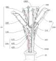
图1是本发明一实施例示出的瓣膜夹合器的结构示意图;Fig. 1 is a schematic structural view of a valve clamp shown in an embodiment of the present invention;
图2是图1示出的瓣膜夹合器的钳臂和夹片均相对于固定基座收拢的侧视示意图;Fig. 2 is a schematic side view of the valve clamp shown in Fig. 1, with both the clamp arms and the clips folded relative to the fixed base;
图3是图1示出的瓣膜夹合器的钳臂相对于固定基座展开,夹片相对于固定基座收拢后的侧视示意图;Fig. 3 is a schematic side view of the clamp arm of the valve clamp shown in Fig. 1 unfolded relative to the fixed base, and the clips folded relative to the fixed base;
图4是图1示出的瓣膜夹合器的钳臂和夹片均相对于固定基座展开的侧视示意图;Fig. 4 is a schematic side view of the valve clamp shown in Fig. 1 where both the forceps arms and the clips are deployed relative to the fixed base;
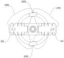
图5是图1示出的瓣膜夹合器的部分结构俯视示意图;Fig. 5 is a schematic top view of a partial structure of the valve clamp shown in Fig. 1;
图6是本发明一实施例示出的瓣膜夹合器通过输送装置经心尖插入心脏的示意图;Fig. 6 is a schematic diagram showing a valve clamp inserted into the heart through the delivery device through the apex according to an embodiment of the present invention;
图7是本发明一实施例示出的瓣膜夹合器在输送装置的操控下夹合二尖瓣的瓣叶的示意图;Fig. 7 is a schematic diagram of a valve clamper clamping the leaflets of the mitral valve under the control of the delivery device according to an embodiment of the present invention;
图8是本发明一实施例示出的瓣膜夹合器在输送装置的操控下与输送装置分离的示意图;Fig. 8 is a schematic diagram showing that the valve clamp is separated from the delivery device under the control of the delivery device according to an embodiment of the present invention;
图9是本发明一实施例示出的另一种瓣膜夹合器的结构示意图;Fig. 9 is a schematic structural view of another valve clamp shown in an embodiment of the present invention;
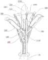
图10是本发明一实施例示出的又一种瓣膜夹合器的结构示意图;Fig. 10 is a schematic structural view of another valve clamp shown in an embodiment of the present invention;
图11是图10的部分结构俯视示意图;Fig. 11 is a schematic top view of part of the structure of Fig. 10;
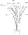
图12是本发明一实施例示出的再一种瓣膜夹合器的结构示意图;Fig. 12 is a schematic structural view of another valve clamp shown in an embodiment of the present invention;
图13是本发明一实施例示出的瓣膜夹合系统的结构示意图;Fig. 13 is a schematic structural view of a valve clamping system shown in an embodiment of the present invention;
图14是本发明一实施例示出的瓣膜夹合系统的瓣膜夹合器与输送装置分离后的结构示意图;Fig. 14 is a schematic structural view of the valve clamping device of the valve clamping system after being separated from the delivery device according to an embodiment of the present invention;
图15是本发明一实施例示出的瓣膜夹合系统中输送装置的另一导线器与夹片和控制线的连接示意图;Fig. 15 is a schematic diagram showing the connection of another guide wire of the delivery device in the valve clamping system, the clip and the control wire according to an embodiment of the present invention;
图16是图15示出的输送装置的导线器与夹片和控制线的俯视示意图。Fig. 16 is a schematic top view of the wire guide, clips and control wires of the delivery device shown in Fig. 15 .
主要元件符号说明:Description of main component symbols:
LV、左心室;LA、左心房;MV、二尖瓣;LV, left ventricle; LA, left atrium; MV, mitral valve;
10、瓣膜夹合器;10. Valve clamp;
20、输送装置;20. Conveying device;
100、固定基座;100, fixed base;
200、钳臂;210、连接臂;220、夹持臂;200, clamp arm; 210, connecting arm; 220, clamping arm;
300、夹片;300, clip;
400、驱动组件;410、驱动轴;420、锁座;430、连杆;440、套管;400, drive assembly; 410, drive shaft; 420, lock seat; 430, connecting rod; 440, bushing;
500、阻塞体;510、连接部;520、弹性球囊;500, blocking body; 510, connecting portion; 520, elastic balloon;
600、导线件;610、支撑杆;620、穿线环;600, wire fitting; 610, support rod; 620, threading ring;
700、输送鞘管;700. Delivery sheath;
800、操控手柄;800. Control handle;
900、控制杆;910、空心管;920、插杆;900, control rod; 910, hollow tube; 920, plunger;
1000、控制线;1000. Control line;
2000、导线器;2100、连接杆;2200、穿线圈。2000, wire guide; 2100, connecting rod; 2200, threading coil.
具体实施方式Detailed ways
为了便于理解本发明,下面将参照相关附图对本发明进行更全面的描述。附图中给出了本发明的较佳的实施例。但是,本发明可以通过许多其他不同的形式来实现,并不限于本文所描述的实施例。相反地,提供这些实施例的目的是使对本发明的公开内容的理解更加透彻全面。In order to facilitate the understanding of the present invention, the present invention will be described more fully below with reference to the associated drawings. Preferred embodiments of the invention are shown in the accompanying drawings. However, the present invention can be embodied in many other different forms and is not limited to the embodiments described herein. On the contrary, these embodiments are provided to make the understanding of the disclosure of the present invention more thorough and comprehensive.
需要说明的是,当元件被称为“固定于”或“设置于”另一个元件,它可以直接在另一个元件上或者间接在该另一个元件上。当一个元件被称为是“连接于”另一个元件,它可以是直接连接到另一个元件或间接连接至该另一个元件上。It should be noted that when an element is referred to as being “fixed” or “disposed on” another element, it may be directly on the other element or be indirectly on the other element. When an element is referred to as being "connected to" another element, it can be directly connected to the other element or indirectly connected to the other element.
此外,术语“第一”、“第二”仅用于描述目的,而不能理解为指示或暗示相对重要性或者隐含指明所指示的技术特征的数量。由此,限定有“第一”、“第二”的特征可以明示或者隐含地包括一个或者更多个该特征。在本申请的描述中,“多个”的含义是两个或两个以上,除非另有明确具体的限定。In addition, the terms "first" and "second" are used for descriptive purposes only, and cannot be interpreted as indicating or implying relative importance or implicitly specifying the quantity of indicated technical features. Thus, a feature defined as "first" and "second" may explicitly or implicitly include one or more of these features. In the description of the present application, "plurality" means two or more, unless otherwise specifically defined.
除非另有定义,本文所使用的所有的技术和科学术语与属于本发明的技术领域的技术人员通常理解的含义相同。本文中在本发明的说明书中所使用的术语只是为了描述具体的实施例的目的,不是旨在于限制本发明。本文所使用的术语“及/或”包括一个或多个相关的所列项目的任意的和所有的组合。Unless otherwise defined, all technical and scientific terms used herein have the same meaning as commonly understood by one of ordinary skill in the technical field of the invention. The terms used herein in the description of the present invention are for the purpose of describing specific embodiments only, and are not intended to limit the present invention. As used herein, the term "and/or" includes any and all combinations of one or more of the associated listed items.
需要说明的是,在介入式医疗器械中,将靠近手术操作者的一端称为“近端”,将远离手术操作者的一端称为“远端”,并依据此原理定义医疗器械中的任一部件的“近端”和“远端”。此外,本文中所述的“前”是指远离操作者的方向,“后”是指指向操作者的方向。It should be noted that in interventional medical devices, the end close to the operator is called "proximal end", and the end far away from the operator is called "distal end", and any medical device is defined according to this principle. The "near end" and "distal end" of a component. In addition, "front" referred to herein refers to a direction away from the operator, and "rear" refers to a direction toward the operator.
正如背景技术中所记载的,传统瓣膜夹合器多为经股静脉穿刺,从上腔静脉穿过房间隔进入左心房,从左心房往下送至二尖瓣附近。由于此路径比较长且迂曲,通常需要多向可调弯的输送装置来配合使用,同时对房间隔穿刺位置要求较高,操作比较复杂,耗时较久,对医生的操作技巧要求较高。As described in the Background Art, traditional valve clamps are mostly punctured through the femoral vein, from the superior vena cava through the interatrial septum into the left atrium, and sent down from the left atrium to near the mitral valve. Because this path is relatively long and tortuous, it usually requires a multi-directional adjustable delivery device to cooperate with it. At the same time, it requires a higher position for atrial septal puncture, the operation is more complicated, time-consuming, and requires higher operating skills of doctors.
为了解决上述问题,根据本申请的一个方面,本申请的实施例提供了一种瓣膜夹合器,如图1-图4所示,该瓣膜夹合器10包括固定基座100、钳臂200、与钳臂200数量相同的夹片300以及驱动组件400。至少一对钳臂200的近端与固定基座100连接,至少一对钳臂200能够相对于固定基座100开合;每一夹片300位于固定基座100与每一钳臂200之间;驱动组件400包括与固定基座 100连接的驱动轴410,驱动轴410沿自身的轴向移动以带动钳臂200相对于固定基座100开合,驱动轴410的近端用于可拆卸地连接输送装置20,输送装置 20用于输送瓣膜夹合器10并控制驱动轴410沿自身的轴向移动,以及控制夹片 300相对于固定基座100开合,以使每一夹片300与其对应的钳臂200配合以夹持瓣膜。In order to solve the above problems, according to one aspect of the present application, an embodiment of the present application provides a valve clamp, as shown in FIGS. , the number of
在本发明实施例中,瓣膜夹合器10通过将至少一对钳臂200的近端与固定基座100连接,与钳臂200数量相同的夹片300位于固定基座100与各钳臂200之间,通过驱动组件400驱动固定基座100带动钳臂200的近端运动,以带动钳臂200相对于固定基座100开合,配合输送装置20控制夹片300相对于固定基座100开合,以使每一夹片300与其对应的钳臂200配合以夹持瓣膜,使用该瓣膜夹合器10可以经心尖从左心室送至二尖瓣附近,手术入口距离瓣膜很近,输送路径短且直,输送装置20无需调弯,易于调整和控制,耗时较短,手术操作较容易,对医生的操作技巧要求不高。In the embodiment of the present invention, the
此外,可以理解的是,由于该瓣膜夹合器10可以由胸部小切口和心尖穿刺口从左心室送至二尖瓣附近,因此无需数字减影血管造影(Digital subtraction angiography)配合使用,减少对医生和患者的危害。In addition, it can be understood that since the
本实施例中,钳臂200与夹片300的数量均为两个,其中,两个夹片300 均由具有形状记忆功能的材料制成,优选超弹性的镍钛合金。可以理解的是,两夹片300的自然状态为相对于固定基座100展开,通过输送装置20控制夹片 300的远端(即自由端)相对于固定基座100收拢以便于输送,而在解除对夹片 300的远端的控制后,夹片300的自由端被释放,夹片300由于自身弹性记忆性能回弹并恢复自然状态,以将瓣叶压向与其对应的钳臂200,实现对瓣叶的夹持。两个钳臂200与两个夹片300一一对应以构成两个夹钳,且两个夹钳关于固定基座100轴对称设置。通过输送装置20将瓣膜夹合器10输送至患者的二尖瓣处,两个夹钳可分别夹持二尖瓣的前叶和后叶以减小瓣叶间隙,并作为植入物留在患者的体内,以减轻或治疗患者的“二尖瓣反流”。In this embodiment, there are two
该瓣膜夹合器10至少具有三种形态,分别为钳臂200和夹片300均完全收拢的第一形态、钳臂200完全展开且夹片300完全收拢的第二形态以及钳臂200 和夹片300均完全展开的第三形态。如图2所示,第一形态为瓣膜夹合器10被输送时的形态;如图3所示,第二形态为钳臂200被驱动组件400驱动而展开的状态(即钳臂200与夹片300组成的夹钳打开的状态),此状态下通过调整瓣膜夹合器10,使收拢的夹片300穿过前叶和后叶之间的间隙并位于瓣叶上方适当位置以将二尖瓣的前叶和后叶分别置于两夹钳中;如图4所示,第三状态为输送装置20解除对夹片300远端的控制后,夹片300由于自身弹性记忆性能展开,以将瓣叶压向与其对应的钳臂200,实现对瓣叶的夹持(即钳臂200与夹片300组成的夹钳闭合的状态)。The
使用该瓣膜夹合器10治疗二尖瓣关闭不全时,如图6-图8所示,将瓣膜夹合器10设置在输送装置20的远端并使其处于上述的第一状态,经胸部小切口和心尖穿刺口从左心室LV送至二尖瓣MV附近,通过输送装置20控制驱动组件 400带动钳臂200展开以形成上述的第二状态,调整瓣膜夹合器10的位置使二尖瓣MV的前叶和后叶分别置于两夹钳中,通过输送装置20解除对夹片300的控制使夹片300自由展开以形成上述的第三状态,使得瓣膜夹合器10的两个夹钳分别夹持二尖瓣MV的前叶和后叶以减小瓣叶间隙,然后控制输送装置20使其远端与瓣膜夹合器10分离,撤出输送装置20,将瓣膜夹合器10作为植入物留在患者的体内,以减轻或治疗患者的“二尖瓣反流”。When using the
在一种实施例中,如图9所示,瓣膜夹合器10还包括阻塞体500,阻塞体 500包括连接部510和弹性球囊520,弹性球囊520的近端通过连接部510连接于固定基座100的远端,弹性球囊520的远端悬空。In one embodiment, as shown in FIG. 9 , the
通过在固定基座100的远端设置阻塞体500,在手术过程中,阻塞体500放置在二尖瓣的前后叶间起定位作用,使瓣膜夹合器10始终定位在二尖瓣的中间位置。当瓣膜夹合器10闭合后,弹性球囊520填充于被夹持的二尖瓣的前叶和后叶之间,且抵顶于钳臂200,因此还具有以下优点:(1)弹性球囊520对于搏动的瓣叶具有缓冲作用,从而实现瓣膜夹合器10对瓣叶的牵拉程度可调节,以避免损伤瓣叶;(2)弹性球囊520可以跟随瓣叶的搏动而被挤压变形,产生的弹力将瓣叶靠近弹性球囊520的部分向远离固定基座100的方向推动,使得二尖瓣的前叶和后叶之间的夹合角度小于钳臂200之间的张开角度,能够减少瓣膜夹合器10对瓣叶的牵拉,使得瓣膜夹合器10对瓣叶的牵拉程度始终保持在合理范围内;(3)弹性球囊520可以缓冲血流对瓣膜夹合器10内部的直接冲刷,避免瓣膜夹合器10受到血液的连续冲刷而脱落,还可以避免血液在瓣膜夹合器的夹持部之间的死角处淤积形成血栓。By setting the blocking
在一些具体的实施例中,阻塞体500具有超声可探测性。In some specific embodiments, the obstructing
通过将阻塞体500设置为具有超声可探测性,使瓣膜夹合器10在超声下易被识别并准确定位。By setting the blocking
具体来说,阻塞体500可采用或植入超声下可探测的材料制成。Specifically, the blocking
在一种实施例中,如图10-图12所示,瓣膜夹合器10还包括导线件600,导线件600设置于固定基座100的远端,导线件600上设置有过线孔,输送装置20中的控制线1000活动穿设于过线孔内并连接于夹片300的远端,控制线 1000用于控制夹片300相对于固定基座100开合。In one embodiment, as shown in FIG. 10-FIG. 12, the
通过在固定基座100的远端设置导线件600,导线件600配合输送装置20 中的控制线1000以对夹片300更好地进行控制。By disposing the
在一种具体的实施例中,如图10-图12所示,导线件600位于固定基座100 的中心轴线上,导线件600包括与固定基座100连接的支撑杆610和设置于支撑杆610的远端的至少一个穿线环620,每一穿线环620上均设置一过线孔。In a specific embodiment, as shown in FIGS. 10-12 , the
将导线件600设置于固定基座100的中心轴线上,在通过穿设于过线孔内的控制线1000拉动夹片300的活动端时,作用在夹片300上的拉力的合力通过导线件600作用于输送装置20的中心轴线上,使得该合力对瓣膜夹合器10产生的力矩为零,从而避免输送装置20的输送鞘管700弯曲导致瓣膜夹合器10 发生摆动移位,方便手术操作,有利于缩短手术时间、提高手术效率。The
此外,由此设计,当支撑杆610的远端设置一个穿线环620时,如图10- 图11所示,可以只需要一根穿设于过线孔的控制线1000与所有的夹片300自由端穿设连接便可实现所有夹片300的同时拉起和放下。In addition, with this design, when a
需要说明的是,在现实情况下,为在手术中操作更加灵活便捷,适用不同的使用需求,控制线1000的数量通常与夹片300的数量相同,各控制线1000 与各夹片300的活动端一一对应穿设连接,由此可实现夹片300同时被拉起和放下或独立拉起和放下,当支撑杆610的远端连接一个穿线环620时,所有的控制线1000均穿设在一个过线孔内,线与线之间的摩擦容易导致控制线1000 缠绕或卡顿;当支撑杆610的远端连接与控制线1000数量相同的穿线环620时,每根控制线1000可以单独穿设在相应的过线孔内,这样可以避免线与线摩擦导致控制线1000卡顿和缠绕。It should be noted that, in reality, in order to make operation more flexible and convenient during surgery, and to adapt to different usage requirements, the number of
在一些具体的实施例中,如图1-图12所示,钳臂200包括连接臂210以及连接于连接臂210远离固定基座100的一端的夹持臂220,连接臂210远离夹持臂220的一端铰接于固定基座100,每一夹持臂220与其对应的夹片300之间形成瓣叶容纳空间;驱动组件400还包括锁座420以及与钳臂200数量相同的连杆430,锁座420活动套设于驱动轴410上并连接于夹片300的远端,每一钳臂 200与锁座420之间设置一连杆430,各连杆430的两端分别连接于锁座420和与其对应的钳臂200的连接臂210与夹持臂220之间。In some specific embodiments, as shown in FIGS. 1-12 , the
为保证植入后的安全性,固定基座100、钳臂200、锁座420、连杆430和驱动轴410可由不锈钢、钴合金、钴铬合金或钛合金等生物相容性金属材料制成。In order to ensure the safety after implantation, the fixed
根据本申请的另一个方面,本申请的实施例还提供了一种瓣膜夹合系统,如图13所示,该瓣膜夹合系统包括上述的瓣膜夹合器10以及输送装置20。输送装置20的远端可拆卸地连接瓣膜夹合器10,输送装置20用于输送瓣膜夹合器10并控制驱动轴410沿自身的轴向移动,以及控制夹片300相对于固定基座 100开合,以使每一夹片300与其对应的钳臂200配合以夹持瓣膜。According to another aspect of the present application, the embodiment of the present application also provides a valve clamping system, as shown in FIG. 13 , the valve clamping system includes the above-mentioned
由于采用了上述的瓣膜夹合器10,该瓣膜夹合系统相应地也具备上述瓣膜夹合器10所带来的有点和好处,在此不再赘述。Due to the use of the
在一种实施例中,如图13-图14所示,该输送装置20包括输送鞘管700、控制手柄、控制杆900以及至少一根控制线1000,操控手柄800设置于输送鞘管700的近端;控制杆900活动穿设于输送鞘管700的内部,控制杆900的远端可拆卸地连接于驱动轴410,控制杆900的近端连接于操控手柄800;至少一根控制线1000活动穿设于输送鞘管700的内部,控制线1000穿设于夹片300 的远端,控制线1000的两末端连接于操控手柄800。In one embodiment, as shown in FIGS. 13-14 , the
具体来说,控制杆900包括活动穿设于输送鞘管700内的空心管910和活动穿设于所述空心管910内的插杆920,插杆920的远端设置有螺纹槽,相应地,驱动组件400还包括与锁座420的近端固定连接的套管440,驱动轴410活动穿设于套管440内,驱动轴410的远端与固定基座100固接,通过推拉驱动轴410 使其相对于套管440沿轴向运动以使钳臂200相对于固定基座100展开和收拢。套管440的近端及空心管910的远端分别形成有可配合卡接的限位槽及限位凸缘,套管440与空心管910对合后限位槽与限位凸缘沿空心管910的轴向相卡持,利用操控手柄800前推插杆920,使插杆920的远端伸入套管440内,可使套管440与空心管910沿插杆920的径向被锁定,转动插杆920,使插杆920的前端与驱动轴410螺接,从而实现控制杆900与驱动轴410的连接固定,通过操控手柄800推拉插杆920可控制钳臂200的开合,通过操控手柄800转动空心管910可调整瓣膜夹合器10转动;当瓣膜夹合器10夹持二尖瓣的前叶和后叶后,利用操控手柄800转动插杆920使其与驱动轴410解除螺接,然后通过操控手柄800回拉插杆920,使插杆920的远端从套管440内撤出,可使限位槽与限位凸缘沿空心管910的径向分离以解除空心管910与套管440的连接,从而实现控制杆900与驱动轴410的分离。Specifically, the
其中,控制线1000选自镍钛丝、不锈钢丝或高强度的高分子线。Wherein, the
在一种具体的实施例中,如图1-图5和图9、图15-图16所示,输送装置 20还包括两个导线器2000,两导线器2000设置于输送鞘管700的远端并关于输送鞘管700的中心轴线对称,导线器2000包括穿线圈2200和连接于穿线圈 2200与输送鞘管700的远端之间的连接杆2100,每一穿线圈2200上均设置有一穿线孔。In a specific embodiment, as shown in FIGS. 1-5 and 9 , and 15-16 , the
将两导线器2000关于输送鞘管700的中心轴线对称设置,在通过控制线 1000控制夹片300相对于固定基座100收拢时,作用在夹片300上的拉力的合力通过两导线器2000作用于输送鞘管700的中心轴线上,使得该合力对瓣膜夹合器10产生的力矩为零,从而避免输送鞘管700弯曲导致瓣膜夹合器10发生摆动移位,方便手术操作,有利于缩短手术时间、提高手术效率。The two
在一种更加具体的实施例中,如图1-图5和图9、图15-图16所示,控制线1000的数量与夹片300的数量相同,每一控制线1000与两导线器2000上的穿线孔和一夹片300的远端穿设连接。In a more specific embodiment, as shown in Fig. 1-Fig. 5 and Fig. 9, Fig. 15-Fig. The threading hole on the 2000 is threaded and connected with the far end of a
将控制线1000的数量设置为与夹片300的数量相同,各控制线1000与各夹片300的活动端一一对应穿设连接,由此可实现夹片300同时被拉起和放下或独立拉起和放下。The number of
以一根控制线1000和与该控制线1000对应连接的夹片300为例阐述控制线1000、导线器2000与夹片300之间的连接方式,控制线1000的一端与操控手柄800连接,控制线1000的活动端经输送鞘管700内部穿设至输送鞘管700 的远端,然后依次穿过一导线器2000上的穿线孔、夹片300活动端的通孔和另一导线器2000上的穿线孔后经输送鞘管700内部穿设至输送鞘管700的远端并于操控手柄800连接。Take a
具体来说,如图1-图5和图9所示,每一个导线器2000中的穿线圈2200 的数量可以是一个。当然,如图15-图16所示,每一个导线器2000中的穿线圈 2200的数量也可以是与夹片300数量相同的多个,如此,可以使得每根控制线 1000的一端单独穿设在导线器2000相应的穿线圈2200中,这样可以避免线与线摩擦,导致控制线1000卡顿和缠绕。Specifically, as shown in FIGS. 1-5 and 9 , the number of
进一步地,输送鞘管700的内部沿轴向设置有多个相互隔离的孔腔,以使每根控制线1000独立穿设于一孔腔内,从而避免线与线之间的摩擦导致缠绕和卡顿。Further, the interior of the
综上,实施本实施例提供的瓣膜夹合器及瓣膜夹合系统,至少具有以下有益技术效果:To sum up, implementing the valve clamp and valve clamping system provided by this embodiment has at least the following beneficial technical effects:
该瓣膜夹合器通过将至少一对钳臂的近端与固定基座连接,与钳臂数量相同的夹片位于固定基座与各钳臂之间,通过驱动组件驱动固定基座带动钳臂的近端运动,以带动钳臂相对于固定基座开合,配合输送装置控制夹片相对于固定基座开合,以使每一夹片与其对应的钳臂配合以夹持瓣膜,使用该瓣膜夹合器可以经心尖从左心室送至二尖瓣附近,手术入口距离瓣膜很近,输送路径短且直,输送装置无需调弯,易于调整和控制,耗时较短,手术操作较容易,对医生的操作技巧要求不高。The valve clamp connects the proximal ends of at least one pair of forceps arms to the fixed base, the clips with the same number as the forceps arms are located between the fixed base and each forceps arm, and the drive assembly drives the fixed base to drive the forceps arms The proximal movement to drive the forceps arm to open and close relative to the fixed base, and cooperate with the delivery device to control the opening and closing of the clips relative to the fixed base, so that each clip cooperates with its corresponding forceps arm to clamp the valve. The valve clamp can be sent from the left ventricle to the vicinity of the mitral valve through the apex of the heart, the surgical entrance is very close to the valve, the delivery path is short and straight, the delivery device does not need to be bent, easy to adjust and control, takes less time, and the operation is easier , The doctor's operating skills are not required.
以上实施例的各技术特征可以进行任意的组合,为使描述简洁,未对上述实施例中的各个技术特征所有可能的组合都进行描述,然而,只要这些技术特征的组合不存在矛盾,都应当认为是本说明书记载的范围。The technical features of the above embodiments can be combined arbitrarily. For the sake of concise description, all possible combinations of the technical features in the above embodiments are not described. However, as long as there is no contradiction in the combination of these technical features, they should be It is considered to be within the range described in this specification.
以上实施例仅表达了本发明的几种实施方式,其描述较为具体和详细,但并不能因此而理解为对申请范围的限制。应当指出的是,对于本领域的普通技术人员来说,在不脱离本发明构思的前提下,还可以做出若干变形和改进,这些都属于本发明的保护范围。因此,本发明的保护范围应以所附权利要求为准。The above examples only express several implementations of the present invention, and the description thereof is relatively specific and detailed, but should not be construed as limiting the scope of application. It should be noted that those skilled in the art can make several modifications and improvements without departing from the concept of the present invention, and these all belong to the protection scope of the present invention. Therefore, the protection scope of the present invention should be determined by the appended claims.
Claims (10)
Translated fromChinesePriority Applications (2)
| Application Number | Priority Date | Filing Date | Title |
|---|---|---|---|
| CN202111627769.2ACN116350393A (en) | 2021-12-28 | 2021-12-28 | Valve clamp and valve clamp system |
| PCT/CN2022/140425WO2023125162A1 (en) | 2021-12-28 | 2022-12-20 | Valve clip and valve clip system |
Applications Claiming Priority (1)
| Application Number | Priority Date | Filing Date | Title |
|---|---|---|---|
| CN202111627769.2ACN116350393A (en) | 2021-12-28 | 2021-12-28 | Valve clamp and valve clamp system |
Publications (1)
| Publication Number | Publication Date |
|---|---|
| CN116350393Atrue CN116350393A (en) | 2023-06-30 |
Family
ID=86929130
Family Applications (1)
| Application Number | Title | Priority Date | Filing Date |
|---|---|---|---|
| CN202111627769.2APendingCN116350393A (en) | 2021-12-28 | 2021-12-28 | Valve clamp and valve clamp system |
Country Status (2)
| Country | Link |
|---|---|
| CN (1) | CN116350393A (en) |
| WO (1) | WO2023125162A1 (en) |
Families Citing this family (4)
| Publication number | Priority date | Publication date | Assignee | Title |
|---|---|---|---|---|
| CN116919663B (en)* | 2023-09-18 | 2024-01-05 | 上海汇禾医疗器械有限公司 | Valve clamping piece device and use method |
| CN116942373B (en)* | 2023-09-18 | 2023-12-12 | 上海汇禾医疗器械有限公司 | Synchronous control handle device and use method thereof |
| CN118986421B (en)* | 2024-08-12 | 2025-08-01 | 宁夏医科大学总医院 | Colorectal polyp biopsy mechanism capable of being controlled accurately |
| CN119235509B (en)* | 2024-10-16 | 2025-08-12 | 苏州金翼医疗科技有限公司 | Double-wing structure clamp for inhibiting mitral regurgitation and conveying equipment thereof |
Citations (5)
| Publication number | Priority date | Publication date | Assignee | Title |
|---|---|---|---|---|
| CN111789699A (en)* | 2019-11-19 | 2020-10-20 | 杭州德晋医疗科技有限公司 | Independently controllable valve clamping system |
| WO2021008461A1 (en)* | 2019-07-12 | 2021-01-21 | 杭州德晋医疗科技有限公司 | Easily operable valve clamping device and valve clamping system |
| CN213722143U (en)* | 2020-08-14 | 2021-07-20 | 先健科技(深圳)有限公司 | Tissue closure device |
| CN215130900U (en)* | 2021-01-15 | 2021-12-14 | 杭州德晋医疗科技有限公司 | Self-adaptive valve clamping device and valve clamping system |
| CN217611577U (en)* | 2021-12-28 | 2022-10-21 | 瀚芯医疗科技(深圳)有限公司 | Valve clamping device and valve clamping system |
Family Cites Families (4)
| Publication number | Priority date | Publication date | Assignee | Title |
|---|---|---|---|---|
| US9572666B2 (en)* | 2014-03-17 | 2017-02-21 | Evalve, Inc. | Mitral valve fixation device removal devices and methods |
| CN112274297B (en)* | 2019-07-24 | 2025-08-01 | 上海形状记忆合金材料有限公司 | Transcatheter heart valve clamping system |
| CN111772874B (en)* | 2019-08-06 | 2024-11-05 | 上海捍宇医疗科技股份有限公司 | A valve clamp and a clamping system thereof |
| CN215130898U (en)* | 2021-01-15 | 2021-12-14 | 杭州德晋医疗科技有限公司 | Valve clamping device and valve clamping system with full fitting |
- 2021
- 2021-12-28CNCN202111627769.2Apatent/CN116350393A/enactivePending
- 2022
- 2022-12-20WOPCT/CN2022/140425patent/WO2023125162A1/ennot_activeCeased
Patent Citations (5)
| Publication number | Priority date | Publication date | Assignee | Title |
|---|---|---|---|---|
| WO2021008461A1 (en)* | 2019-07-12 | 2021-01-21 | 杭州德晋医疗科技有限公司 | Easily operable valve clamping device and valve clamping system |
| CN111789699A (en)* | 2019-11-19 | 2020-10-20 | 杭州德晋医疗科技有限公司 | Independently controllable valve clamping system |
| CN213722143U (en)* | 2020-08-14 | 2021-07-20 | 先健科技(深圳)有限公司 | Tissue closure device |
| CN215130900U (en)* | 2021-01-15 | 2021-12-14 | 杭州德晋医疗科技有限公司 | Self-adaptive valve clamping device and valve clamping system |
| CN217611577U (en)* | 2021-12-28 | 2022-10-21 | 瀚芯医疗科技(深圳)有限公司 | Valve clamping device and valve clamping system |
Also Published As
| Publication number | Publication date |
|---|---|
| WO2023125162A1 (en) | 2023-07-06 |
Similar Documents
| Publication | Publication Date | Title |
|---|---|---|
| CN212490263U (en) | Valve clamping device with adjustable supporting force and valve clamping system | |
| US20220142780A1 (en) | Adjustable valve clip and valve clamping system | |
| CN116350393A (en) | Valve clamp and valve clamp system | |
| CN110495972B (en) | Valve clip and valve clip system | |
| CN112386368B (en) | Adjustable valve clamp and valve clamping system | |
| CN110996851B (en) | Heart valve implant and heart valve implant system | |
| CN111772875B (en) | Compressible valve clamp and clamping system thereof | |
| CN217611577U (en) | Valve clamping device and valve clamping system | |
| JP5518735B2 (en) | Heart valve downsizing apparatus and method | |
| CN109953779A (en) | Clamping device and system for securing tissue | |
| WO2019114448A1 (en) | Artificial chordae tendineae fixing assembly capable of adjusting multiple times and intervention method thereof | |
| US12083014B2 (en) | Fixing device for clamping tissue | |
| CN115486972A (en) | A Displacement System Avoiding Outflow Tract Obstruction | |
| CN212346819U (en) | Multidimensional fixed heart valve prosthesis | |
| CN115429492B (en) | Valve clamping device and valve clamping system | |
| CN109350307A (en) | A transcatheter artificial valve replacement system | |
| CN113208778A (en) | Anchoring device | |
| CN113413240A (en) | Multidimensional fixed heart valve prosthesis | |
| WO2024067686A1 (en) | Mitral valve clamping device and mitral valve clamping system | |
| CN113317910A (en) | Mitral annuloplasty system and method of operation thereof | |
| CN114376766B (en) | Adjustable and removable valve clamping device | |
| CN209186798U (en) | Adjustable suture lock knot device | |
| JP2023515809A (en) | Transcatheter valve leads and valve elements | |
| WO2022083027A1 (en) | Adjustable and removable valve clamping device | |
| CN114073602A (en) | Valve clamping device with adjustable supporting force and valve clamping system |
Legal Events
| Date | Code | Title | Description |
|---|---|---|---|
| PB01 | Publication | ||
| PB01 | Publication | ||
| SE01 | Entry into force of request for substantive examination | ||
| SE01 | Entry into force of request for substantive examination |