CN116350313A - Atherosclerosis excision device - Google Patents
Atherosclerosis excision deviceDownload PDFInfo
- Publication number
- CN116350313A CN116350313ACN202310095372.6ACN202310095372ACN116350313ACN 116350313 ACN116350313 ACN 116350313ACN 202310095372 ACN202310095372 ACN 202310095372ACN 116350313 ACN116350313 ACN 116350313A
- Authority
- CN
- China
- Prior art keywords
- cutting
- optical fiber
- tube
- catheter
- drive
- Prior art date
- Legal status (The legal status is an assumption and is not a legal conclusion. Google has not performed a legal analysis and makes no representation as to the accuracy of the status listed.)
- Pending
Links
Images


Classifications
- A—HUMAN NECESSITIES
- A61—MEDICAL OR VETERINARY SCIENCE; HYGIENE
- A61B—DIAGNOSIS; SURGERY; IDENTIFICATION
- A61B17/00—Surgical instruments, devices or methods
- A61B17/32—Surgical cutting instruments
- A61B17/3205—Excision instruments
- A61B17/3207—Atherectomy devices working by cutting or abrading; Similar devices specially adapted for non-vascular obstructions
- A61B17/320758—Atherectomy devices working by cutting or abrading; Similar devices specially adapted for non-vascular obstructions with a rotating cutting instrument, e.g. motor driven
- A—HUMAN NECESSITIES
- A61—MEDICAL OR VETERINARY SCIENCE; HYGIENE
- A61B—DIAGNOSIS; SURGERY; IDENTIFICATION
- A61B90/00—Instruments, implements or accessories specially adapted for surgery or diagnosis and not covered by any of the groups A61B1/00 - A61B50/00, e.g. for luxation treatment or for protecting wound edges
- A61B90/36—Image-producing devices or illumination devices not otherwise provided for
- A61B90/37—Surgical systems with images on a monitor during operation
- A—HUMAN NECESSITIES
- A61—MEDICAL OR VETERINARY SCIENCE; HYGIENE
- A61B—DIAGNOSIS; SURGERY; IDENTIFICATION
- A61B17/00—Surgical instruments, devices or methods
- A61B17/32—Surgical cutting instruments
- A61B2017/320052—Guides for cutting instruments
- A—HUMAN NECESSITIES
- A61—MEDICAL OR VETERINARY SCIENCE; HYGIENE
- A61B—DIAGNOSIS; SURGERY; IDENTIFICATION
- A61B17/00—Surgical instruments, devices or methods
- A61B17/32—Surgical cutting instruments
- A61B2017/320064—Surgical cutting instruments with tissue or sample retaining means
- A—HUMAN NECESSITIES
- A61—MEDICAL OR VETERINARY SCIENCE; HYGIENE
- A61B—DIAGNOSIS; SURGERY; IDENTIFICATION
- A61B17/00—Surgical instruments, devices or methods
- A61B17/32—Surgical cutting instruments
- A61B17/3205—Excision instruments
- A61B17/3207—Atherectomy devices working by cutting or abrading; Similar devices specially adapted for non-vascular obstructions
- A61B2017/320741—Atherectomy devices working by cutting or abrading; Similar devices specially adapted for non-vascular obstructions for stripping the intima or the internal plaque from a blood vessel, e.g. for endarterectomy
- A—HUMAN NECESSITIES
- A61—MEDICAL OR VETERINARY SCIENCE; HYGIENE
- A61B—DIAGNOSIS; SURGERY; IDENTIFICATION
- A61B90/00—Instruments, implements or accessories specially adapted for surgery or diagnosis and not covered by any of the groups A61B1/00 - A61B50/00, e.g. for luxation treatment or for protecting wound edges
- A61B90/36—Image-producing devices or illumination devices not otherwise provided for
- A61B90/37—Surgical systems with images on a monitor during operation
- A61B2090/373—Surgical systems with images on a monitor during operation using light, e.g. by using optical scanners
- A61B2090/3735—Optical coherence tomography [OCT]
- Y—GENERAL TAGGING OF NEW TECHNOLOGICAL DEVELOPMENTS; GENERAL TAGGING OF CROSS-SECTIONAL TECHNOLOGIES SPANNING OVER SEVERAL SECTIONS OF THE IPC; TECHNICAL SUBJECTS COVERED BY FORMER USPC CROSS-REFERENCE ART COLLECTIONS [XRACs] AND DIGESTS
- Y02—TECHNOLOGIES OR APPLICATIONS FOR MITIGATION OR ADAPTATION AGAINST CLIMATE CHANGE
- Y02W—CLIMATE CHANGE MITIGATION TECHNOLOGIES RELATED TO WASTEWATER TREATMENT OR WASTE MANAGEMENT
- Y02W30/00—Technologies for solid waste management
- Y02W30/50—Reuse, recycling or recovery technologies
- Y02W30/62—Plastics recycling; Rubber recycling
Landscapes
- Health & Medical Sciences (AREA)
- Life Sciences & Earth Sciences (AREA)
- Surgery (AREA)
- Nuclear Medicine, Radiotherapy & Molecular Imaging (AREA)
- Medical Informatics (AREA)
- Veterinary Medicine (AREA)
- Biomedical Technology (AREA)
- Heart & Thoracic Surgery (AREA)
- Engineering & Computer Science (AREA)
- Molecular Biology (AREA)
- Animal Behavior & Ethology (AREA)
- General Health & Medical Sciences (AREA)
- Public Health (AREA)
- Vascular Medicine (AREA)
- Gynecology & Obstetrics (AREA)
- Radiology & Medical Imaging (AREA)
- Oral & Maxillofacial Surgery (AREA)
- Pathology (AREA)
- Surgical Instruments (AREA)
Abstract
Translated fromChinese
Description
Translated fromChinese技术领域technical field
本发明涉及医疗器械领域,具体而言,涉及一种动脉粥样硬化切除装置。The invention relates to the field of medical devices, in particular to an atherosclerosis resection device.
背景技术Background technique
脂质沉积在动脉的血管内膜通常会引发动脉粥样硬化,从而引起全身的系统性以及进展性疾病。目前,针对粥样斑块的去除,除了药物治疗外,还可通过血管影像的引导,使用旋切与旋磨装置,将动脉粥样硬化斑块从血管壁上切下或磨碎,通过导管排出体外。Lipid deposition in the intima of arteries often leads to atherosclerosis, which can lead to systemic and progressive disease throughout the body. At present, in addition to drug treatment, for the removal of atherosclerotic plaques, guided by vascular images, rotary cutting and rotational atherectomy devices can be used to cut or grind atherosclerotic plaques from the blood vessel wall, and pass through the catheter excreted.
然而现有的治疗方式无法直观、准确且清晰地显现出病变血管,因此无法在实时可视的条件下有效地处理动脉硬化斑块,不仅如此,还容易对血管的正常部位造成损伤。However, the existing treatment methods cannot intuitively, accurately and clearly display the diseased blood vessels, so they cannot effectively deal with the atherosclerotic plaques under real-time visualization conditions, not only that, but also easily cause damage to the normal parts of the blood vessels.
发明内容Contents of the invention
本发明提供了一种动脉粥样硬化切除装置,其能够在实时可视的条件下进行动脉斑块旋切手术,降低旋切对正常部位损伤的风险。The present invention provides an atherosclerosis resection device, which can perform rotary atherosclerosis surgery under real-time and visible conditions, and reduce the risk of damage to normal parts caused by rotary atherectomy.
本发明的实施例可以这样实现:Embodiments of the present invention can be realized like this:
第一方面,本发明提供一种动脉粥样硬化切除装置,包括导管、切割件以及光纤;In a first aspect, the present invention provides an atherosclerosis resection device, including a catheter, a cutting element, and an optical fiber;
所述导管与所述切割件连接,用于带动所述切割件轴向旋转以进行切割;The conduit is connected to the cutting element, and is used to drive the cutting element to rotate axially for cutting;
所述光纤设置于所述导管并与所述切割件连接,所述光纤用于所述切割件旋转的过程中发射以及接收光信号。The optical fiber is arranged on the guide tube and connected to the cutting part, and the optical fiber is used for transmitting and receiving light signals during the rotation of the cutting part.
在可选的实施方式中,所述导管内设置有第一驱动管和第二驱动管,所述第一驱动管可活动地套设在所述第二驱动管外,所述光纤设置于所述第一驱动管,所述第二驱动管与所述切割件连接,用于带动所述切割件轴向旋转。In an optional embodiment, a first driving tube and a second driving tube are arranged inside the catheter, the first driving tube is movably sleeved outside the second driving tube, and the optical fiber is arranged on the The first driving tube is connected with the cutting part, and the second driving tube is used to drive the cutting part to rotate axially.
在可选的实施方式中,所述第二驱动管设置有第一通道,所述切割件开设有第二通道,所述第二通道贯穿所述切割件的两端,所述第二通道与所述第一通道连通,并共同用于穿设导丝。In an optional embodiment, the second drive tube is provided with a first channel, and the cutting member is provided with a second channel, and the second channel runs through both ends of the cutting member, and the second channel and The first channel communicates and is jointly used for threading a guide wire.
在可选的实施方式中,所述动脉粥样硬化切除装置还包括收集管,所述收集管与所述切割件远离所述导管的一端连接,所述收集管用于收集所述切割件切割的斑块。In an optional embodiment, the atherosclerosis resection device further includes a collection tube, the collection tube is connected to the end of the cutting member away from the catheter, and the collection tube is used to collect the plaque.
在可选的实施方式中,所述切割件开设有凹槽,所述凹槽与所述收集管相对设置,所述凹槽用于容置所述斑块。In an optional embodiment, the cutting member is provided with a groove, the groove is disposed opposite to the collecting tube, and the groove is used for accommodating the plaque.
在可选的实施方式中,所述动脉粥样硬化切除装置还包括复位件,所述复位件的一端与所述收集管连接,另一端与所述导管连接,所述复位件相对所述导管呈外凸弧形状。In an optional embodiment, the atherosclerosis removal device further includes a reset member, one end of the reset member is connected to the collecting tube, and the other end is connected to the catheter, and the reset member is opposite to the guide tube. It is in the shape of a convex arc.
在可选的实施方式中,所述收集管与所述切割件铰接,所述导管设置有第三通道,所述第三通道内设置有连接线,所述复位件与所述连接线连接,所述连接线用于拉动所述复位件,以使所述复位件产生形变并带动所述收集管与所述切割件呈夹角设置。In an optional embodiment, the collecting tube is hinged to the cutting member, the conduit is provided with a third channel, a connecting line is provided in the third channel, and the reset member is connected to the connecting line, The connecting wire is used to pull the reset member, so that the reset member is deformed and drives the collection pipe to form an included angle with the cutting member.
在可选的实施方式中,所述切割件的外壁设置有切割部,所述切割部沿所述切割件的轴线方向延伸或呈螺旋延伸。In an optional embodiment, the outer wall of the cutting member is provided with a cutting portion, and the cutting portion extends along the axis of the cutting member or extends in a spiral.
在可选的实施方式中,所述切割件开设有相互连通的第一腔室和第二腔室,所述第一腔室用于供所述光纤伸入,所述第二腔室用于容置透镜以及棱镜,所述切割件的外壁开设有出光窗口,所述出光窗口与所述第二腔室连通,所述棱镜与所述出光窗口对应设置;所述光纤的端部与所述透镜间隔设置。In an optional embodiment, the cutting member is provided with a first chamber and a second chamber communicated with each other, the first chamber is used for inserting the optical fiber, and the second chamber is used for Accommodating a lens and a prism, the outer wall of the cutting member is provided with a light exit window, the light exit window communicates with the second chamber, the prism is arranged correspondingly to the light exit window; the end of the optical fiber is connected to the Lens spacing settings.
在可选的实施方式中,所述动脉粥样硬化切除装置还包括相互连接的连接器以及驱动处理器,所述第一驱动管和所述第二驱动管均与所述连接器连接,所述连接器用于带动所述第一驱动管和所述第二驱动管转动,所述光纤通过所述连接器与所述驱动处理器连接,所述驱动处理器用于为所述连接器提供驱动力并用于处理所述光信号。In an optional embodiment, the atherosclerosis resection device further includes an interconnected connector and a drive processor, the first drive tube and the second drive tube are both connected to the connector, so The connector is used to drive the first driving tube and the second driving tube to rotate, the optical fiber is connected to the driving processor through the connector, and the driving processor is used to provide driving force for the connector And for processing the optical signal.
本发明实施例提供的动脉粥样硬化切除装置的有益效果包括:切割件在导管的带动下进行旋切,可对血管内的斑块进行有效切割;而光纤在旋转的过程中发射近红外光,并收集由血管壁反射或散射的光信号,以此完成血管内光学相干层析成像,成像清晰准确,因此实现了在实时可视的条件下进行动脉斑块旋切手术,提高了旋切手术的操控性,显著降低了切割件的旋切动作对正常部位损伤的风险。The beneficial effects of the atherosclerosis resection device provided by the embodiment of the present invention include: the cutting part is driven by the catheter to perform rotary cutting, which can effectively cut the plaque in the blood vessel; and the optical fiber emits near-infrared light during the rotation process , and collect the light signal reflected or scattered by the blood vessel wall to complete intravascular optical coherence tomography. The maneuverability of the operation significantly reduces the risk of damage to normal parts caused by the rotary cutting action of the cutting piece.
附图说明Description of drawings
为了更清楚地说明本发明实施例的技术方案,下面将对实施例中所需要使用的附图作简单地介绍,应当理解,以下附图仅示出了本发明的某些实施例,因此不应被看作是对范围的限定,对于本领域普通技术人员来讲,在不付出创造性劳动的前提下,还可以根据这些附图获得其他相关的附图。In order to illustrate the technical solutions of the embodiments of the present invention more clearly, the accompanying drawings used in the embodiments will be briefly introduced below. It should be understood that the following drawings only show some embodiments of the present invention, and thus It should be regarded as a limitation on the scope, and those skilled in the art can also obtain other related drawings based on these drawings without creative work.
图1为本发明实施例提供的动脉粥样硬化切除装置结构示意图之一;Figure 1 is one of the structural schematic diagrams of the atherosclerosis resection device provided by the embodiment of the present invention;
图2为本发明实施例提供的动脉粥样硬化切除装置结构示意图之二;Fig. 2 is the second structural schematic diagram of the atherosclerosis resection device provided by the embodiment of the present invention;
图3为本发明实施例提供的第一驱动管和第二驱动管截面示意图;3 is a schematic cross-sectional view of a first drive tube and a second drive tube provided by an embodiment of the present invention;
图4为本发明实施例提供的切割件剖视图;Fig. 4 is the sectional view of the cutting piece provided by the embodiment of the present invention;
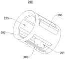
图5为本发明实施例提供的切割件第一实施例示意图;Fig. 5 is a schematic diagram of the first embodiment of the cutting member provided by the embodiment of the present invention;
图6为本发明实施例提供的切割件第二实施例示意图。Fig. 6 is a schematic diagram of a second embodiment of a cutting member provided by an embodiment of the present invention.
图标:10-动脉粥样硬化切除装置;100-导管;110-第一驱动管;120-第二驱动管;121-第一通道;130-第三通道;200-切割件;210-第二通道;220-凹槽;230-第一腔室;240-第二腔室;250-透镜;260-棱镜;270-出光窗口;280-切割部;290-切刀;291-收集孔;292-刃口部;300-光纤;400-收集管;500-复位件;600-连接器;610-接头;700-驱动处理器。Icons: 10 - atherectomy device; 100 - catheter; 110 - first driving tube; 120 - second driving tube; 121 - first channel; 130 - third channel; 200 - cutting piece; 210 - second Channel; 220-groove; 230-first chamber; 240-second chamber; 250-lens; 260-prism; 270-light window; 280-cutting part; - cutting edge; 300 - optical fiber; 400 - collection tube; 500 - reset piece; 600 - connector; 610 - connector; 700 - drive processor.
具体实施方式Detailed ways
为使本发明实施例的目的、技术方案和优点更加清楚,下面将结合本发明实施例中的附图,对本发明实施例中的技术方案进行清楚、完整地描述,显然,所描述的实施例是本发明一部分实施例,而不是全部的实施例。通常在此处附图中描述和示出的本发明实施例的组件可以以各种不同的配置来布置和设计。In order to make the purpose, technical solutions and advantages of the embodiments of the present invention clearer, the technical solutions in the embodiments of the present invention will be clearly and completely described below in conjunction with the drawings in the embodiments of the present invention. Obviously, the described embodiments It is a part of embodiments of the present invention, but not all embodiments. The components of the embodiments of the invention generally described and illustrated in the figures herein may be arranged and designed in a variety of different configurations.
因此,以下对在附图中提供的本发明的实施例的详细描述并非旨在限制要求保护的本发明的范围,而是仅仅表示本发明的选定实施例。基于本发明中的实施例,本领域普通技术人员在没有作出创造性劳动前提下所获得的所有其他实施例,都属于本发明保护的范围。Accordingly, the following detailed description of the embodiments of the invention provided in the accompanying drawings is not intended to limit the scope of the claimed invention, but merely represents selected embodiments of the invention. Based on the embodiments of the present invention, all other embodiments obtained by persons of ordinary skill in the art without creative efforts fall within the protection scope of the present invention.
应注意到:相似的标号和字母在下面的附图中表示类似项,因此,一旦某一项在一个附图中被定义,则在随后的附图中不需要对其进行进一步定义和解释。It should be noted that like numerals and letters denote similar items in the following figures, therefore, once an item is defined in one figure, it does not require further definition and explanation in subsequent figures.
在本发明的描述中,需要说明的是,若出现术语“上”、“下”、“内”、“外”等指示的方位或位置关系为基于附图所示的方位或位置关系,或者是该发明产品使用时惯常摆放的方位或位置关系,仅是为了便于描述本发明和简化描述,而不是指示或暗示所指的装置或元件必须具有特定的方位、以特定的方位构造和操作,因此不能理解为对本发明的限制。In the description of the present invention, it should be noted that if the orientation or positional relationship indicated by the terms "upper", "lower", "inner" and "outer" appear, it is based on the orientation or positional relationship shown in the drawings, or It is the orientation or positional relationship that the invention product is usually placed in use, and it is only for the convenience of describing the present invention and simplifying the description, rather than indicating or implying that the referred device or element must have a specific orientation, be constructed and operated in a specific orientation , and therefore cannot be construed as a limitation of the present invention.
此外,若出现术语“第一”、“第二”等仅用于区分描述,而不能理解为指示或暗示相对重要性。In addition, terms such as "first" and "second" are used only for distinguishing descriptions, and should not be understood as indicating or implying relative importance.
需要说明的是,在不冲突的情况下,本发明的实施例中的特征可以相互结合。It should be noted that, in the case of no conflict, the features in the embodiments of the present invention may be combined with each other.
动脉粥样硬化主要是由于脂质沉积在动脉的血管内膜而发生的多种病变,是全身系统性、进展性疾病。当形成的粥样斑块影响正常血流时就会产生所支配区域组织的缺血症状。而且,所形成的粥样斑块可能破裂,引起血栓,造成整条血管的完全或不完全闭塞,导致的临床表现也随着器官的不同而不同,如心脏缺血主要表现为心绞痛或心肌梗死,脑血管则表现为脑供血不足、脑梗死甚至脑溢血,下肢动脉表现为剧烈疼痛或间歇性跛行。治疗该类疾病最主要的方法是恢复被斑块或血栓阻断的血流,既能够减轻甚至消除症状,又能够改善远期预后。Atherosclerosis is mainly a variety of lesions that occur due to lipid deposition in the intima of arteries. It is a systemic and progressive disease throughout the body. Ischemia of the innervated area occurs when atheromatous plaques form that interfere with normal blood flow. Moreover, the formed atherosclerotic plaque may rupture, causing thrombus, resulting in complete or incomplete occlusion of the entire blood vessel, resulting in different clinical manifestations with different organs, such as cardiac ischemia mainly manifested as angina pectoris or myocardial infarction Cerebral vessels manifest as cerebral insufficiency, cerebral infarction or even cerebral hemorrhage, and arteries of the lower extremities manifest as severe pain or intermittent claudication. The most important way to treat such diseases is to restore the blood flow blocked by plaque or thrombus, which can not only reduce or even eliminate symptoms, but also improve the long-term prognosis.
目前,针对粥样斑块的去除,除了药物治疗外,还可通过血管影像的引导,使用旋切与旋磨装置,将动脉硬化斑块从血管壁上切下或磨碎,通过导管排出体外。At present, for the removal of atherosclerotic plaque, in addition to drug treatment, it is also possible to use rotary cutting and rotary atherectomy devices to cut or grind atherosclerotic plaque from the blood vessel wall under the guidance of vascular images, and then pass it out of the body through a catheter .
然而现有的治疗方式无法直观、准确且清晰地显现出病变血管,因此无法在实时可视的条件下有效地处理动脉硬化斑块,不仅如此,还容易对血管的正常部位造成损伤。However, the existing treatment methods cannot intuitively, accurately and clearly display the diseased blood vessels, so they cannot effectively deal with the atherosclerotic plaques under real-time visualization conditions, not only that, but also easily cause damage to the normal parts of the blood vessels.
因此,基于以上问题,本发明提供了一种动脉粥样硬化切除装置,用于在实时可视的条件下进行动脉斑块旋切手术,能降低旋切对正常部位损伤的风险。Therefore, based on the above problems, the present invention provides an atherosclerosis resection device, which is used to perform rotary atherosclerosis surgery under real-time visualization conditions, which can reduce the risk of damage to normal parts caused by rotary atherectomy.
请参阅图1至图4,本发明提供的动脉粥样硬化切除装置10包括导管100、切割件200、光纤300、收集管400、复位件500、连接器600以及驱动处理器700,其中,驱动处理器700、连接器600、导管100、切割件200以及收集管400依次连接,复位件500的两端分别与导管100以及收集管400连接;光纤300设置于导管100内,并依次与驱动处理器700、连接器600、导管100以及切割件200连接,连接器600为中继装置,由驱动处理器700为其提供斑块旋切术所需的能量,并对光纤300接受的光信号进行处理;导管100、切割件200以及收集管400用于伸入血管中以进行斑块去除手术和实时监控,以此实时可视的条件下进行动脉斑块旋切手术,从而显著降低旋切对正常部位损伤的风险。1 to 4, the
具体地,连接器600的端部设置有与第一驱动管110和第二驱动管120匹配的接头610,第一驱动管110和第二驱动管120均与连接器600上的接头610连接,以通过接头610同时或分别带动第一驱动管110和第二驱动管120转动,光纤300通过连接器600与驱动处理器700连接,由驱动处理器700为连接器600提供驱动力并用于处理光信号。Specifically, the end of the
进一步地,导管100用于带动切割件200轴向旋转以进行切割,光纤300设置于导管100并与切割件200连接,光纤300用于切割件200旋转的过程中发射以及接收光信号。Further, the
在本实施例中,切割件200在导管100的带动下进行旋切,可对血管内的斑块进行有效切割;而光纤300在旋转的过程中发射近红外光,并收集由血管壁反射或散射的光信号,以此完成血管内光学相干层析成像,成像清晰准确,因此实现了在实时可视的条件下进行动脉斑块旋切手术,提高了旋切手术的操控性,显著降低了切割件200的旋切动作对正常部位损伤的风险。In this embodiment, the
需要说明的是,导管壁是由高分子材料构成,且呈中空编织管状结构。It should be noted that the catheter wall is made of polymer material and has a hollow braided tubular structure.
进一步地,导管100包括第一驱动管110和第二驱动管120,第一驱动管110可活动地套设在第二驱动管120外,导管100还包括外壳(图未示),外壳可活动地套设在第一驱动管110外,外壳可对第一驱动管110和第二驱动管120起到保护作用。光纤300设置于第一驱动管110,第二驱动管120与切割件200连接,用于带动切割件200轴向旋转。Further, the
在本实施例中,在正常情况下光纤300呈松散状缠绕在第一驱动管110上。在连接器600带动切割件200转动的情况下,连接器600同时带动第二驱动管120相对第一驱动管110伸出,以使得光纤300呈拉伸状并贴近第一驱动管110的内壁;而在连接器600未带动切割件200转动的情况下,使得切割件200在第二驱动管120的带动下相对第一驱动管110回撤,以使光纤300收缩并贴近第一驱动管110的外壁;以此可以避免第一驱动管110和第二驱动管120以同向或以反向旋转的情况下与光纤300摩擦导致光纤300损伤,此外,相对现有的切割导管100,通过以上设置使得导管100占用体积更小。In this embodiment, under normal conditions, the
需要说明的是,第一驱动管110和第二驱动管120可以是中空的扭矩传输结构的弹簧管。It should be noted that the
进一步地,第二驱动管120的内部设置有第一通道121,切割件200开设有第二通道210,第二通道210贯穿切割件200的两端,第二通道210与第一通道121连通,并共同用于穿设导丝(图未示)。Further, the inside of the
需要说明的是,通常将导丝依次穿过第一通道121和第二通道210,并将导丝远离切割件200的一端提前设置到待进行旋切手术的血管内,以此通过导丝为导管100及切割件200在血管内的运动进行导向,使其精准地运动至待进行旋切手术部位。It should be noted that, usually, the guide wire is passed through the
进一步地,收集管400与切割件200远离导管100的一端连接,收集管400用于收集切割件200切割的斑块,切割件200开设有凹槽220,凹槽220与收集管400相对设置,凹槽220用于容置切割形成的斑块。Further, the collecting
在本实施例中,收集管400在与凹槽220相对的一端设置有入口(图未示),在切割件200进行旋切后脱落的斑块可先通过凹槽220进行收集,再将凹槽220内的斑块导入至收集管400内,以此通过收集管400将斑块排出体外。In this embodiment, the
具体地,凹槽220的底壁呈弧形凹陷状,凹槽220的开口所形成的刃口可起到一定切削作用,而具有弧形平滑凹陷状底壁的凹槽220可将切削下来的斑块导入收集管400内。Specifically, the bottom wall of the
进一步地,复位件500的一端与收集管400连接,另一端与导管100连接,复位件500相对导管100呈外凸弧形状。Further, one end of the
在本实施例中,复位件500采用热处理定型以使复位件500具有形变回复能力,即使复位件500循环往复地发生形变也能恢复原样。因此通过设置呈外凸弧形板状的复位件500,可代替使用球囊,从而避免球囊破裂的风险,降低手术风险。另外,与传统的球囊相比,复位件500所占体积远小于球囊,有利于经过狭窄的血管,并可有效增加导管100、切割件200或收集管400的利用空间。In this embodiment, the
可选地,复位件500可采用具有弹性功能的簧片。Optionally, the resetting
进一步地,收集管400与切割件200铰接,导管100设置有第三通道130,第三通道130内设置有连接线(图未示),复位件500与连接线连接,连接线用于拉动复位件500,以使复位件500产生形变并带动收集管400与切割件200呈夹角设置。Further, the collecting
在本实施例中,第三通道130设置于第一驱动管110和导管100的外壳之间,也可设置于导管100的外壳的内壁,其导管100的外壳由高分子材料制成。In this embodiment, the
在本实施例中,收集管400与切割件200可转动地连接,通过连接线拉动复位件500以产生形变,从而带动收集管400和切割件200相对转动,以此达到调节切割件200旋切方向的目的。而在连接线对复位件500的拉力作用撤销后,复位件500通过弹性回复力形变至原始状态。另外,通过连接线带动收集管400与切割件200呈夹角设置,以方便将凹槽220内的斑块导入到收集管400内。In this embodiment, the collecting
需要说明的是,连接线与连接器600连接,并通过连接器600为连接线提供拉力。It should be noted that the connecting wire is connected to the
进一步地,切割件200开设有相互连通的第一腔室230和第二腔室240,第一腔室230用于供光纤300伸入,第二腔室240用于容置透镜250以及棱镜260,切割件200的外壁开设有出光窗口270,出光窗口270与第二腔室240连通,棱镜260与出光窗口270对应设置。Further, the cutting
在本实施例中,光纤300传输的光依次通过透镜250以及棱镜260,其中,透镜250起到汇聚作用,棱镜260起到反射作用,以此使得光束从出光窗口270窗口发射和接收,从而完成相干光成像。In this embodiment, the light transmitted by the
具体地,光纤300的端部与透镜250间隔设置,且间隔可以是0mm~2mm,以此提高光纤300传输的光的汇聚作用。Specifically, the end of the
可选地,透镜250可以是格林透镜,棱镜260可以是直角棱镜。Optionally, the
需要说明的是,第二驱动管120可伸入切割件200的第一腔室230内并与第一腔室230焊接,光纤300从第一驱动管110的端部穿出,并伸入第一腔室230内。第一驱动管110可相对第二驱动管120轴向移动,以实现调节出光窗口270的视角。It should be noted that the
请参阅图5和图6,切割件200靠近收集管400的端部设置有呈筒状的切刀290,切刀290的外壁设置有切割部280,切割部280沿切割件200的轴线方向延伸或呈螺旋延伸,凹槽220设置于切刀290的内部。Referring to FIGS. 5 and 6 , the end of the cutting
在本实施例中,切割部280的数量可以为多个,多个切割部280均匀地设置在切割件200的周向外壁上。In this embodiment, there may be multiple cutting
需要说明的是,如图5所示,切割部280可以沿切割件200的轴线方向延伸,在此实施例中,切刀290在切割部280处还开设有与切割部280对应的收集孔291,收集孔291与凹槽220连通,以便于切割部280切割斑块后使得斑块通过收集孔291容置于凹槽220内;另外,在切刀的端部还设置有刃口部292,刃口部292即为凹槽220的开口所形成的刃口,以加强切刀290的切割效果。It should be noted that, as shown in FIG. 5 , the cutting
如图6所示,切割部280还可以呈螺旋延伸,换言之,通过设置不同形状的切割部280,可增加切割件200切削面积,从而增大切削效率,大大降低手术时间,以减轻病人痛苦,当然,还可根据实际不同的需求对切割部280进行相应的调整,以此提高切割件200的适应性。As shown in Figure 6, the cutting
另外还需要说明的是,图所示的仅为切割部280的结构示意,并非为切割件200的实际结构。In addition, it should be noted that what is shown in the figure is only a schematic structure of the cutting
具体地,动脉粥样硬化切除装置10的工作过程包括:首先将导丝穿设于动脉粥样硬化切除装置10,并将导丝提前导入血管内,以使动脉粥样硬化切除装置10在导丝的导向作用下进入到血管的手术部位;连接器600在驱动处理器700的驱动下带动第一驱动管110和/或第二驱动管120转动,由第二驱动管120带动切割件200转动,以通过切割件200上的切割部280进行切割,切割下的斑块可通过切割件200前端的凹槽220进行初步容置,再由凹槽220将容置的斑块导入至收集管内,以此实现将斑块带离出血管;在切割件200旋转的过程中光纤300通过出光窗口270发射近红外光,并收集由血管壁反射或散射的光信号,将光信号传输至驱动处理器进行处理,以此得到实时且清晰的血管内光学相干层析成像;在此过程中,还可通过连接器600以及驱动处理器700的控制下拉动与复位件500连接的连接线,从而使得复位件500产生弹性形变,以此可改变切割件200的切割方向,从而有利于切除斑块。Specifically, the working process of the atherosclerosis resection device 10 includes: firstly, the guide wire is passed through the atherosclerosis resection device 10, and the guide wire is introduced into the blood vessel in advance, so that the atherosclerosis resection device 10 Under the guidance of the wire, it enters the surgical site of the blood vessel; the connector 600 drives the first drive tube 110 and/or the second drive tube 120 to rotate under the drive of the drive processor 700, and the second drive tube 120 drives the cutting member 200 to rotate , so as to cut through the cutting part 280 on the cutting part 200, the cut plaque can be initially accommodated through the groove 220 at the front end of the cutting part 200, and then the accommodated plaque is introduced into the collection tube through the groove 220, In this way, the plaque is taken out of the blood vessel; during the rotation of the cutting member 200, the optical fiber 300 emits near-infrared light through the light exit window 270, collects the light signal reflected or scattered by the blood vessel wall, and transmits the light signal to the drive processor process to obtain real-time and clear intravascular optical coherence tomography; during this process, the connection line connected to the reset member 500 can also be pulled under the control of the connector 600 and the drive processor 700, so that the reset The elastic deformation of the member 500 can change the cutting direction of the cutting member 200, thereby facilitating the removal of the plaque.
综上所述,本发明实施例提供了一种动脉粥样硬化切除装置10,切割件200在导管100的带动下进行旋切,可对血管内的斑块进行有效切割;而光纤300在旋转的过程中发射近红外光,并收集由血管壁反射或散射的光信号,以此完成血管内光学相干层析成像,成像清晰准确,因此实现了在实时可视的条件下进行动脉斑块旋切手术,提高了旋切手术的操控性,显著降低了切割件200的旋切动作对正常部位损伤的风险。To sum up, the embodiment of the present invention provides an
以上所述,仅为本发明的具体实施方式,但本发明的保护范围并不局限于此,任何熟悉本技术领域的技术人员在本发明揭露的技术范围内,可轻易想到的变化或替换,都应涵盖在本发明的保护范围之内。因此,本发明的保护范围应以所述权利要求的保护范围为准。The above is only a specific embodiment of the present invention, but the scope of protection of the present invention is not limited thereto. Anyone skilled in the art can easily think of changes or substitutions within the technical scope disclosed in the present invention. All should be covered within the protection scope of the present invention. Therefore, the protection scope of the present invention should be determined by the protection scope of the claims.
Claims (10)
Priority Applications (1)
| Application Number | Priority Date | Filing Date | Title |
|---|---|---|---|
| CN202310095372.6ACN116350313A (en) | 2023-02-07 | 2023-02-07 | Atherosclerosis excision device |
Applications Claiming Priority (1)
| Application Number | Priority Date | Filing Date | Title |
|---|---|---|---|
| CN202310095372.6ACN116350313A (en) | 2023-02-07 | 2023-02-07 | Atherosclerosis excision device |
Publications (1)
| Publication Number | Publication Date |
|---|---|
| CN116350313Atrue CN116350313A (en) | 2023-06-30 |
Family
ID=86930923
Family Applications (1)
| Application Number | Title | Priority Date | Filing Date |
|---|---|---|---|
| CN202310095372.6APendingCN116350313A (en) | 2023-02-07 | 2023-02-07 | Atherosclerosis excision device |
Country Status (1)
| Country | Link |
|---|---|
| CN (1) | CN116350313A (en) |
Cited By (2)
| Publication number | Priority date | Publication date | Assignee | Title |
|---|---|---|---|---|
| CN116746987A (en)* | 2023-08-10 | 2023-09-15 | 乐普(北京)医疗器械股份有限公司 | Cutting and collecting catheter and intravascular calcified plaque removing device |
| CN119214747A (en)* | 2024-10-23 | 2024-12-31 | 南京鼓楼医院 | Atherosclerosis excision device |
Citations (5)
| Publication number | Priority date | Publication date | Assignee | Title |
|---|---|---|---|---|
| US5759185A (en)* | 1994-10-24 | 1998-06-02 | Smith & Nephew, Inc. | Surgical instrument |
| CN102159144A (en)* | 2008-02-25 | 2011-08-17 | 福克斯霍洛技术股份有限公司 | Methods and devices for cutting tissue |
| US20150208922A1 (en)* | 2010-07-01 | 2015-07-30 | Avinger,Inc | Balloon atherectomy catheters with imaging |
| US20150272615A1 (en)* | 2011-03-28 | 2015-10-01 | Avinger, Inc. | Occlusion-crossing devices |
| CN106413592A (en)* | 2014-02-06 | 2017-02-15 | 尼普洛株式会社 | catheter |
- 2023
- 2023-02-07CNCN202310095372.6Apatent/CN116350313A/enactivePending
Patent Citations (5)
| Publication number | Priority date | Publication date | Assignee | Title |
|---|---|---|---|---|
| US5759185A (en)* | 1994-10-24 | 1998-06-02 | Smith & Nephew, Inc. | Surgical instrument |
| CN102159144A (en)* | 2008-02-25 | 2011-08-17 | 福克斯霍洛技术股份有限公司 | Methods and devices for cutting tissue |
| US20150208922A1 (en)* | 2010-07-01 | 2015-07-30 | Avinger,Inc | Balloon atherectomy catheters with imaging |
| US20150272615A1 (en)* | 2011-03-28 | 2015-10-01 | Avinger, Inc. | Occlusion-crossing devices |
| CN106413592A (en)* | 2014-02-06 | 2017-02-15 | 尼普洛株式会社 | catheter |
Cited By (3)
| Publication number | Priority date | Publication date | Assignee | Title |
|---|---|---|---|---|
| CN116746987A (en)* | 2023-08-10 | 2023-09-15 | 乐普(北京)医疗器械股份有限公司 | Cutting and collecting catheter and intravascular calcified plaque removing device |
| CN116746987B (en)* | 2023-08-10 | 2023-11-14 | 乐普(北京)医疗器械股份有限公司 | Cutting and collecting catheter and intravascular calcified plaque removing device |
| CN119214747A (en)* | 2024-10-23 | 2024-12-31 | 南京鼓楼医院 | Atherosclerosis excision device |
Similar Documents
| Publication | Publication Date | Title |
|---|---|---|
| JP7627243B2 (en) | Method for controlling the operation of an imaging system and system for acquiring images - Patents.com | |
| CN116350313A (en) | Atherosclerosis excision device | |
| US5573531A (en) | Fluid core laser angioscope | |
| CA2803992C (en) | Atherectomy catheters with longitudinally displaceable drive shafts | |
| JP6539669B2 (en) | Atherectomy catheter and crossing obstruction device | |
| US11406412B2 (en) | Atherectomy catheters with imaging | |
| JP4271844B2 (en) | Intracavity imaging system and method | |
| US20210085158A1 (en) | Endoscope, endoscope system, insertion portion of endoscope, and calculus collecting method | |
| US20100081873A1 (en) | Systems and methods for optical viewing and therapeutic intervention in blood vessels | |
| US20190298321A1 (en) | Fully integrated endoscope with biopsy capabilitites and methods of use | |
| JP5688160B2 (en) | Flexible weight loss catheter with imaging and methods of use and manufacture thereof | |
| US12226117B2 (en) | Atherectomy apparatus with imaging | |
| US20100121141A1 (en) | Endoscopic cutting and debriding device mounted on a flexible and maneuverable tube employing a fluid-driven turbine | |
| JP2004097286A (en) | Catheter | |
| CN220757447U (en) | Adjustable bending instrument for interventional operation | |
| CN113017780B (en) | Catheter system integrating ultrasonic imaging and rotational atherectomy of plaque in cavity | |
| AU2022350279A1 (en) | Visual ureteroscope | |
| CN113197555A (en) | Multi-direction OCT image acquisition catheter | |
| US12310657B2 (en) | Equipment for crushing urinary stone | |
| KR102534218B1 (en) | Tissue separation and collection device for endoscope and endoscopic image diagnosis device thereof | |
| JP2019209175A (en) | Recovery system for collecting one or plural calculus | |
| JP2015217216A (en) | catheter | |
| JP5784972B2 (en) | Exterior tube, laser transmission path, laser treatment instrument | |
| CN119791787A (en) | Intravascular resection device | |
| US20120116205A1 (en) | Imaging guidewire |
Legal Events
| Date | Code | Title | Description |
|---|---|---|---|
| PB01 | Publication | ||
| PB01 | Publication | ||
| SE01 | Entry into force of request for substantive examination | ||
| SE01 | Entry into force of request for substantive examination |