CN116342839A - Control method of self-guiding soft endoscope based on spatial perception - Google Patents
Control method of self-guiding soft endoscope based on spatial perceptionDownload PDFInfo
- Publication number
- CN116342839A CN116342839ACN202310202621.7ACN202310202621ACN116342839ACN 116342839 ACN116342839 ACN 116342839ACN 202310202621 ACN202310202621 ACN 202310202621ACN 116342839 ACN116342839 ACN 116342839A
- Authority
- CN
- China
- Prior art keywords
- path
- depth
- point
- depth map
- endoscope
- Prior art date
- Legal status (The legal status is an assumption and is not a legal conclusion. Google has not performed a legal analysis and makes no representation as to the accuracy of the status listed.)
- Granted
Links
Images


Classifications
- G—PHYSICS
- G06—COMPUTING OR CALCULATING; COUNTING
- G06T—IMAGE DATA PROCESSING OR GENERATION, IN GENERAL
- G06T19/00—Manipulating 3D models or images for computer graphics
- G06T19/003—Navigation within 3D models or images
- G—PHYSICS
- G06—COMPUTING OR CALCULATING; COUNTING
- G06F—ELECTRIC DIGITAL DATA PROCESSING
- G06F30/00—Computer-aided design [CAD]
- G06F30/10—Geometric CAD
- G—PHYSICS
- G06—COMPUTING OR CALCULATING; COUNTING
- G06T—IMAGE DATA PROCESSING OR GENERATION, IN GENERAL
- G06T17/00—Three dimensional [3D] modelling, e.g. data description of 3D objects
- G—PHYSICS
- G06—COMPUTING OR CALCULATING; COUNTING
- G06F—ELECTRIC DIGITAL DATA PROCESSING
- G06F2111/00—Details relating to CAD techniques
- G06F2111/04—Constraint-based CAD
- Y—GENERAL TAGGING OF NEW TECHNOLOGICAL DEVELOPMENTS; GENERAL TAGGING OF CROSS-SECTIONAL TECHNOLOGIES SPANNING OVER SEVERAL SECTIONS OF THE IPC; TECHNICAL SUBJECTS COVERED BY FORMER USPC CROSS-REFERENCE ART COLLECTIONS [XRACs] AND DIGESTS
- Y02—TECHNOLOGIES OR APPLICATIONS FOR MITIGATION OR ADAPTATION AGAINST CLIMATE CHANGE
- Y02T—CLIMATE CHANGE MITIGATION TECHNOLOGIES RELATED TO TRANSPORTATION
- Y02T10/00—Road transport of goods or passengers
- Y02T10/10—Internal combustion engine [ICE] based vehicles
- Y02T10/40—Engine management systems
Landscapes
- Engineering & Computer Science (AREA)
- Physics & Mathematics (AREA)
- General Physics & Mathematics (AREA)
- Theoretical Computer Science (AREA)
- Software Systems (AREA)
- Geometry (AREA)
- Computer Graphics (AREA)
- Computer Hardware Design (AREA)
- General Engineering & Computer Science (AREA)
- Pure & Applied Mathematics (AREA)
- Evolutionary Computation (AREA)
- Mathematical Optimization (AREA)
- Mathematical Analysis (AREA)
- Computational Mathematics (AREA)
- Radar, Positioning & Navigation (AREA)
- Remote Sensing (AREA)
- Image Analysis (AREA)
- Endoscopes (AREA)
Abstract
Description
Translated fromChinese技术领域Technical Field
本发明属于医疗电子设备的控制方法领域,具体说是基于空间感知的可自主导向软式内镜控制方法。The present invention belongs to the field of control methods for medical electronic equipment, and in particular to a control method for an autonomously steerable flexible endoscope based on space perception.
背景技术Background Art
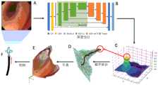
机器人运动和器械控制是机器人内镜检查、内镜控制模拟以及内镜培训的基本问题。根据经验,自主内镜检查的主要挑战是空间感知受限导致的机动性受限。在器官腔体或模型腔体中的弯曲段(如图1中B),由于近端组织对远处区域的遮挡,导致了操作的困难。因此,用于自主内镜导航策略应该感知管腔形状如何延展,以及决策内镜应该在何时何处以什么速度转向和输送。Robotic motion and instrument control are fundamental issues in robotic endoscopy, endoscope control simulation, and endoscopy training. Based on experience, the main challenge of autonomous endoscopy is limited mobility due to limited spatial perception. Curved segments in organ cavities or model cavities (such as B in Figure 1) are difficult to operate due to the obstruction of distant areas by proximal tissues. Therefore, the navigation strategy for autonomous endoscopy should perceive how the lumen shape extends and decide when, where, and at what speed the endoscope should turn and transport.
内镜工作的腔内环境具有封闭的特点,其中内镜是唯一的光源(见图1)。基于这些认识,一类导航的方案是通过寻找视觉特征,如暗区通常被认为是指示行进方向的腔道中心。然而,因为检测暗区或管腔中心的方法只能在内镜图像上提供平面目标,无论组织状态如何,这类方法都只能指示机器人内镜转向而无法对输送进行更多调整。在这种情况下,内镜可能被过度转向到如图1中的②的位置,从而可能接触到组织。内镜与组织的接触可能导致输送不够平滑,从而产生较大的输送力。The intracavitary environment in which the endoscope works is characterized by being closed, in which the endoscope is the only light source (see Figure 1). Based on these understandings, one type of navigation scheme is to find visual features, such as dark areas, which are usually considered to be the center of the lumen indicating the direction of travel. However, because the method of detecting dark areas or the center of the lumen can only provide a planar target on the endoscopic image, regardless of the state of the tissue, this type of method can only instruct the robotic endoscope to turn and cannot make more adjustments to the delivery. In this case, the endoscope may be over-turned to the
为了解决这个问题,一些研究人员通过从人体解剖结构的几何轮廓信息来设计导航方法,其中一个很好的例子是利用结肠的皱褶(见图1-A)。这些方法获得了对具有规则轮廓的部分区域的空间感知。但是当轮廓不可见时,如内镜太接近组织而无法检测轮廓(图1中④)时,或受到剧烈组织运动的影响时,基于解剖结构的方法将失效。因此,这种方法不够稳健,需要大量的额外处理,这可能会降低自主内镜的稳定性和实用性。此外,与解剖结构的密切关系使得此类方法不太普遍适用于其他具有较少可识别轮廓特征的官腔类器官(参见图1中D)。To solve this problem, some researchers have designed navigation methods by deriving geometric contour information from human anatomical structures. A good example is the use of the folds of the colon (see Figure 1-A). These methods gain spatial perception of partial areas with regular contours. However, when the contour is not visible, such as when the endoscope is too close to the tissue to detect the contour (④ in Figure 1), or when affected by violent tissue movement, the anatomical structure-based method will fail. Therefore, this method is not robust enough and requires a lot of additional processing, which may reduce the stability and practicality of autonomous endoscopy. In addition, the close relationship with the anatomical structure makes such methods less generally applicable to other luminal organoids with fewer recognizable contour features (see Figure 1D).
上述利用视觉特征或解剖几何轮廓信息的方法可用于确定内镜转向方向,但由于缺乏三维空间感知,它们无法获得足够的机动性。这可能会导致输送不够顺畅,产生较大的输送力,甚至失去导航。The above-mentioned methods using visual features or anatomical geometric contour information can be used to determine the steering direction of the endoscope, but they cannot obtain sufficient maneuverability due to the lack of three-dimensional spatial perception. This may result in less than smooth delivery, greater delivery force, or even loss of navigation.
发明内容Summary of the invention
本发明提出基于空间感知的可自主导向软式内镜控制方法,包括获取单目内镜图像进行三维空间感知,得到环境空间深度图;对环境空间深度图进行处理,提取导向路径并优化;计算导向路径的几何信息,实现自适应导向控制。The present invention proposes an autonomously steerable flexible endoscope control method based on spatial perception, comprising acquiring a monocular endoscope image for three-dimensional spatial perception to obtain an environmental space depth map; processing the environmental space depth map to extract and optimize a guidance path; and calculating geometric information of the guidance path to achieve adaptive guidance control.
本发明为实现上述目的所采用的技术方案是:基于空间感知的可自主导向软式内镜控制方法,包括以下步骤:The technical solution adopted by the present invention to achieve the above-mentioned purpose is: a method for controlling an autonomously steerable flexible endoscope based on space perception, comprising the following steps:
S1、获取单目内镜图像进行三维空间感知,得到环境空间深度图;S1, obtain a monocular endoscopic image to perform three-dimensional space perception and obtain an environmental space depth map;
S2、对环境空间深度图进行处理,提取导向路径并优化;S2, processing the environment space depth map, extracting and optimizing the guidance path;
S3、计算导向路径的几何信息,实现自适应导向控制。S3. Calculate the geometric information of the guidance path to achieve adaptive guidance control.
所述获取单目内镜图像进行三维空间感知,得到环境空间深度图,采用端到端有监督的深度学习方法,包括以下步骤:The method of acquiring a monocular endoscopic image for three-dimensional space perception and obtaining an environmental space depth map adopts an end-to-end supervised deep learning method, including the following steps:
所述端到端有监督的深度学习方法以单目内镜图像为输入,输出结果为同分辨率的逐像素深度图;The end-to-end supervised deep learning method takes a monocular endoscopic image as input and outputs a pixel-by-pixel depth map of the same resolution;
训练时以合成单目内镜图像为输入,输出的深度图与合成真值深度图对比计算复合损失函数;训练时采用的训练数据,通过以下步骤得到:During training, the synthetic monocular endoscopic image is used as input, and the output depth map is compared with the synthetic true value depth map to calculate the composite loss function; the training data used during training is obtained through the following steps:
获取环境空间的三维模型;Obtain a three-dimensional model of the environment space;
在环境空间中添加纹理,设置虚拟路径;Add textures in the environment space and set virtual paths;
让虚拟相机沿虚拟路径运动;Let the virtual camera move along the virtual path;
通过脚本导出彩色图像和对应的深度数据。Export color images and corresponding depth data through scripts.
所述提取导向路径,包括以下步骤:The extracting guide path comprises the following steps:
选择离散系数和深度范围,将深度图体素化形成二值化的三维深度场网格;Selecting a discrete coefficient and a depth range, voxelizing the depth map to form a binarized three-dimensional depth field grid;
用数字拓扑方法对二值化的三维深度场网格进行迭代缩减,得到离散导向路径。The binarized 3D depth field grid is iteratively reduced using digital topology methods to obtain discrete guided paths.
所述提取导向路径,包括以下步骤:The extracting guide path comprises the following steps:
首先,基于深度转换函数对深度图D进行校正:对于深度图D上的点((i,j)T,d),选择离散化分辨率参数S,则深度转换函数为:First, the depth map D is corrected based on the depth conversion function: for a point ((i, j)T , d) on the depth map D, a discretization resolution parameter S is selected, and the depth conversion function is:

得到

然后,根据数字拓扑的定义,对内点集


在内点集


通过迭代缩减过程构建导向路径
所述通过迭代缩减过程构建导向路径
1)创建空的已删除集


2)在拓扑域
3)记当前邻域方向为dir,创建空的可删除集
4)对每个拓扑域

5)对每个可删除集


6)如果已删除集

所述优化,包括以下步骤:The optimization comprises the following steps:
将离散导向路径转换到深度图上表达,对深度应用校正函数进行处理;Convert the discrete guidance path to a depth map and apply a correction function to the depth.
将校正后的离散点进行逆投影映射,得到空间中的离散中心点;Perform inverse projection mapping on the corrected discrete points to obtain discrete center points in space;
对离散中心点进行平滑、拟合与重采样,获得优化的导向路径。Discrete center points are smoothed, fitted, and resampled to obtain an optimized guidance path.
所述优化,包括以下步骤:The optimization comprises the following steps:
对于每个离散导向路径上的点

得到(i,j,d1)T∈L是深度图域D的点,构成深度图上的导向路径LD,其中d1是经过转换的深度;We get (i, j, d1 )T ∈ L as a point in the depth map domain D, which constitutes a guided pathLD on the depth map, where d1 is the transformed depth;
通过深度校正函数以减少非线性影响:Use a depth correction function to reduce nonlinear effects:

其中,α是校正因子,通常取1.5,d2是经过校正的深度;Where α is the correction factor, usually 1.5, and d2 is the corrected depth;
然后,根据标准针孔相机模型,将深度图上的导向路径LD转换到相机空间


其中,
最后,使用B样条拟合导向路径
所述计算导向路径的几何信息,实现自适应导向控制,包括以下步骤:The step of calculating the geometric information of the guiding path and implementing adaptive guiding control comprises the following steps:
提取优化导向路径的微分几何信息,包括计算曲率和切向量;所述曲率表示导向路径弯曲程度,与内镜调弯速度关联;所述切向量表示导向路径延伸方向,与内镜调弯方向和输送速度关联;Extracting differential geometric information of the optimized guide path, including calculating curvature and tangent vector; the curvature represents the curvature of the guide path and is associated with the bending speed of the endoscope; the tangent vector represents the extension direction of the guide path and is associated with the bending direction of the endoscope and the conveying speed;
从导向路径l的微分几何信息中构建增益矩阵;所述增益矩阵采用导向路径前后端平均切向的内积作为指标参数,自适应选择常规参数或条件参数:当路径弯曲程度小于阈值时,采用常规参数;否则,采用条件参数,通过速度适配律调节内镜弯曲速度和前进速度;A gain matrix is constructed from the differential geometry information of the guide path l; the gain matrix uses the inner product of the average tangent of the front and rear ends of the guide path as an index parameter, and adaptively selects conventional parameters or conditional parameters: when the path curvature is less than a threshold, conventional parameters are used; otherwise, conditional parameters are used to adjust the curvature speed and forward speed of the endoscope through the speed adaptation law;
通过增益矩阵和运动学雅可比把目标误差映射到驱动量,并通过约束参数实现自主控制。The target error is mapped to the actuation quantity through the gain matrix and kinematic Jacobian, and autonomous control is achieved through constraint parameters.
所述计算导向路径的几何信息,实现自适应导向控制,包括以下步骤:The step of calculating the geometric information of the guiding path and implementing adaptive guiding control comprises the following steps:
1)平滑导向路径l转换至Frenet坐标系下的参数化方程l=l(s),其中s是弧长变量;1) The smooth guide path l is transformed into the parameterized equation l=l(s) in the Frenet coordinate system, where s is the arc length variable;
微分几何信息包含切向量t(s):The differential geometry information includes the tangent vector t(s):

微分几何信息包含曲率κ(s):The differential geometry information includes the curvature κ(s):

目标速度大小v与曲率κ(s)关系如下:The relationship between the target velocity v and the curvature κ(s) is as follows:

其次,引入系数函数c=c(s),c>0,c∈[0,1],目标速度方向ve与切向量t(s)关系如下:Secondly, the coefficient function c=c(s), c>0, c∈[0,1] is introduced, and the relationship between the target velocity directionve and the tangent vector t(s) is as follows:

目标速度为:The target speed is:

其中,length(l)表示导向路径总长度;引入速度增益矩阵K作为控制调节系数,增益后的目标速度:Wherein, length(l) represents the total length of the guided path; the speed gain matrix K is introduced as the control adjustment coefficient, and the target speed after gain is:
v'=K·vv'=K·v
2)自适应调节参数E是导向路径不同段的平均切方向的余弦差:2) The adaptive adjustment parameter E is the cosine difference of the average tangent direction of different segments of the guidance path:

其中,L=length(l)是导向路径总长度,kc表示分段比率;Where L = length (l) is the total length of the guided path, kc represents the segment ratio;
3)预先给定切换阈值Ec,若E不小于Ec,K选用参数Ku;反之,选用参数Kc;3) A switching threshold Ec is given in advance. If E is not less than Ec , K uses parameterKu ; otherwise, parameter Kc is used;
其中,in,

其中kbx,kby和kz分别表示X方向转向自由度、Y方向转向自由度和Z方向输送自由度的基准增益系数,其中kz→∞;Where kbx , kby and kz represent the reference gain coefficients of the X-direction steering degree of freedom, the Y-direction steering degree of freedom and the Z-direction transport degree of freedom, respectively, and kz →∞;
Kc与E关联,表示为:Kc is associated with E and is expressed as:

其中kincx,kincy和kdec具有如下形式:where kincx , kincy , and kdec have the following forms:
kincx=kbx·(1+kG·(1-E))kincx =kbx ·(1+kG ·(1-E))
kincy=kby·(1+kG·(1-E))kincy =kby ·(1+kG ·(1-E))
kdec=ka·(1-kS·(1-E))kdec = ka ·(1-kS ·(1-E))
其中,kz′是所选的不同于kz的输送增益参数,kG和kS用于确定控制的响应速度;Wherekz′ is a selected transmission gain parameter different fromkz ,kG andkS are used to determine the response speed of the control;
4)根据选择不同的K,将K作为PID控制的比例增益系数P,控制内镜在X方向转向自由度、Y方向转向自由度和Z方向输送自由度的速度。4) According to different selections of K, K is used as the proportional gain coefficient P of the PID control to control the speed of the endoscope in the X-direction steering freedom, the Y-direction steering freedom and the Z-direction transport freedom.
基于空间感知的可自主导向软式内镜控制系统,包括:The autonomously steerable flexible endoscope control system based on spatial perception includes:
三维空间感知模块,用于获取单目内镜图像进行三维空间感知,得到环境空间深度图;The three-dimensional space perception module is used to obtain the monocular endoscope image for three-dimensional space perception and obtain the environmental space depth map;
路径优化模块,用于对环境空间深度图进行处理,提取导向路径并优化;The path optimization module is used to process the environment space depth map, extract the guidance path and optimize it;
导向控制模块,用于计算导向路径的几何信息,实现自适应导向控制。The guidance control module is used to calculate the geometric information of the guidance path and realize adaptive guidance control.
本发明具有以下有益效果及优点:The present invention has the following beneficial effects and advantages:
1.本发明具有对内镜工作环境的空间进行三维感知的能力;1. The present invention has the ability to perceive the space of the endoscope working environment in three dimensions;
2.本发明具有适应内镜工作环境的空间结构的能力;2. The present invention has the ability to adapt to the spatial structure of the endoscope working environment;
3.在本发明的控制实施下可以实现较小的内镜输送力和更顺畅的内镜输送效果;3. Under the control implementation of the present invention, a smaller endoscope delivery force and a smoother endoscope delivery effect can be achieved;
4.本发明整体流程具有透明化,物理信息明确等优点。4. The overall process of the present invention has the advantages of transparency and clear physical information.
附图说明BRIEF DESCRIPTION OF THE DRAWINGS
图1本发明的工作原理示意图;Fig. 1 is a schematic diagram of the working principle of the present invention;
图2本发明的方法流程图;Fig. 2 is a flow chart of the method of the present invention;
图3本发明的数据集合成方法流程图;FIG3 is a flow chart of a data set synthesis method according to the present invention;
图4数字拓扑提取过程示意图;Fig. 4 Schematic diagram of digital topology extraction process;
图5深度非线性问题示意图;Fig. 5 Schematic diagram of deep nonlinear problem;
图6本发明的控制过程框图。FIG6 is a block diagram of the control process of the present invention.
具体实施方式DETAILED DESCRIPTION
下面结合附图及实施例对本发明做进一步的详细说明。The present invention is further described in detail below in conjunction with the accompanying drawings and embodiments.
如图2所示,一种基于空间感知的腔道自主导向控制策略,主要步骤如下:As shown in Figure 2, a cavity autonomous guidance control strategy based on spatial perception has the following main steps:
S1.从单目内镜图像进行三维空间感知;S1. 3D spatial perception from monocular endoscopic images;
S2.对空间感知结果进行处理,提取导向路径并优化;S2. Process the spatial perception results, extract the guidance path and optimize it;
S3.计算导向路径的几何信息,实现自适应导向控制。S3. Calculate the geometric information of the guidance path and realize adaptive guidance control.
使用端到端有监督的深度学习方法从单目内镜图像中获取深度图。Depth maps are obtained from monocular endoscopic images using an end-to-end supervised deep learning approach.
深度学习方法,其结构是端到端,训练方式是有监督的,使用的训练数据是合成的,输出结果是像素稠密的深度图。The deep learning method has an end-to-end structure, a supervised training method, synthetic training data, and the output result is a pixel-dense depth map.
所使用的端到端的深度学习方法需要以单目内镜图像为输入,输出结果为同分辨率的逐像素深度图。The end-to-end deep learning method used requires a monocular endoscopic image as input and outputs a pixel-by-pixel depth map of the same resolution.
所使用的有监督的深度学习方法在训练时需要以合成单目内镜图像为输入,输出的深度图与合成真值深度图对比计算复合损失函数。The supervised deep learning method used requires a synthetic monocular endoscopic image as input during training, and the output depth map is compared with the synthetic true depth map to calculate a composite loss function.
所输出的深度图是逐像素稠密的,即深度图与输入图像分辨率相同,且每个像素都有深度值。The output depth map is pixel-wise dense, that is, the depth map has the same resolution as the input image and each pixel has a depth value.
训练数据合成方法包含以下步骤:The training data synthesis method includes the following steps:
使用假体模型扫描生成三维模型;Use the prosthetic model to scan and generate a three-dimensional model;
在合成环境中添加纹理,设置虚拟路径;Add textures to the composite environment and set up virtual paths;
让虚拟相机沿着虚拟路径运动;Let the virtual camera move along the virtual path;
通过脚本导出彩色图像和对应的深度数据而得到。The color image and the corresponding depth data are exported by the script.
导向路径提取和优化方法包含以下步骤:The guidance path extraction and optimization method includes the following steps:
从深度图中使用数字拓扑方法提取离散导向路径。Discrete guided paths are extracted from the depth map using digital topology methods.
对离散导向路径进行处理,得到优化的导向路径。The discrete guidance path is processed to obtain an optimized guidance path.
提取导向路径包含以下步骤:Extracting the guide path consists of the following steps:
选择离散系数和深度范围,将深度图体素化形成二值化的三维深度场网格;Selecting a discrete coefficient and a depth range, voxelizing the depth map to form a binarized three-dimensional depth field grid;
用数字拓扑方法对二值化网格进行迭代缩减,得到离散导向路径。The binary grid is iteratively reduced using digital topology methods to obtain discrete guided paths.
导向路径优化包含以下步骤:Guidance path optimization includes the following steps:
将离散导向路径转换到深度图上表达,对深度应用校正函数进行处理;Convert the discrete guidance path to a depth map and apply a correction function to the depth.
处理后导向路径;Processing guide path;
对离散中心点进行平滑、拟合与重采样,获得优化的导向路径。Discrete center points are smoothed, fitted, and resampled to obtain an optimized guidance path.
自适应导向控制方法包含以下步骤:The adaptive guidance control method includes the following steps:
提取优化导向路径的微分几何信息,包括计算曲率和切向量。Extract differential geometry information for the optimized guidance path, including computation of curvature and tangent vectors.
通过映射关系,从微分几何信息中构建增益矩阵。The gain matrix is constructed from the differential geometry information through the mapping relationship.
通过增益矩阵和运动学雅可比把目标误差映射到驱动量,并设计约束参数来提高自主控制效果。The target error is mapped to the driving quantity through the gain matrix and kinematic Jacobian, and the constraint parameters are designed to improve the autonomous control effect.
导向路径微分几何信息提取:曲率表示导向路径弯曲程度,与内镜调弯速度关联;切向量表示导向路径延申方向,与内镜调弯方向和输送速度关联。Extraction of differential geometric information of the guide path: The curvature represents the degree of curvature of the guide path, which is related to the bending speed of the endoscope; the tangent vector represents the extension direction of the guide path, which is related to the bending direction of the endoscope and the conveying speed.
增益矩阵构建:计算导向路径前后端平均切向的内积作为指标参数,自适应选择常规参数还是条件参数:当路径弯曲程度小时,采用常规参数,控制内镜稳定快速输送;当路径弯曲程度大时,采用条件参数,通过速度适配律调节内镜弯曲速度和前进速度,避免偏离导向路径。Gain matrix construction: The inner product of the average tangent of the front and rear ends of the guide path is calculated as the indicator parameter, and conventional parameters or conditional parameters are adaptively selected: when the path curvature is small, conventional parameters are used to control the stable and rapid delivery of the endoscope; when the path curvature is large, conditional parameters are used to adjust the bending speed and forward speed of the endoscope through the speed adaptation law to avoid deviation from the guide path.
约束参数设计包括以下参数:Constraint parameter design includes the following parameters:
最小曲率条件:在弯曲程度过小时,禁用调弯;Minimum curvature condition: when the curvature is too small, the curvature adjustment is disabled;
惯性参数:权衡内镜历史操作和当前操纵,保证内镜行为连续性。Inertia parameters: weigh the endoscope's historical operations and current manipulations to ensure the continuity of endoscope behavior.
如图2所示,空间感知是通过从单目内镜图像重建组织的近似表面来实现的。首先,我们使用神经网络从内镜图像(图2中A)中估计处像素级的深度图(图2中B)。为此,我们构建了一个具有像素级深度图的合成数据集来训练网络。然后,我们使用深度图导出当前场景的腔道导向路径,其中管腔空间是被内镜的视野截断的。进一步地,目标在深度图中的被标识为最深区域(图2中C)。腔道导向路径通过数字拓扑对体素化的深度场进行骨架化来获取(图2中D)。提取的导向路径需要通过平滑和插值(图2中E)进行优化,以便进一步应用与控制机器人内镜转向(图2中F)。As shown in Figure 2, spatial perception is achieved by reconstructing the approximate surface of the tissue from the monocular endoscopic image. First, we use a neural network to estimate the pixel-level depth map (Figure 2B) from the endoscopic image (Figure 2A). To this end, we construct a synthetic dataset with pixel-level depth maps to train the network. Then, we use the depth map to derive the lumen guidance path of the current scene, where the lumen space is truncated by the field of view of the endoscope. Further, the target is identified as the deepest area in the depth map (Figure 2C). The lumen guidance path is obtained by skeletonizing the voxelized depth field through digital topology (Figure 2D). The extracted guidance path needs to be optimized by smoothing and interpolation (Figure 2E) for further application and control of robotic endoscope steering (Figure 2F).
图2描绘了空间感知的整体技术路线。本文除说明外采样表1中公式符号与注记。Figure 2 depicts the overall technical route of spatial perception. In addition to the explanation, this paper samples the formula symbols and notes in Table 1.
表1公式符号说明Table 1 Explanation of formula symbols


1.三维空间感知方法1. Three-dimensional space perception method
所述三维空间感知方法从内镜图像中获取描述三维空间的深度图。具体感知方法为使用深度学习神经网络,以内镜图像为输入,输出为深度图。其中,神经网络使用有监督方法在合成的内镜图像与深度数据上的进行训练而得到。The three-dimensional space perception method obtains a depth map describing the three-dimensional space from the endoscopic image. The specific perception method uses a deep learning neural network, takes the endoscopic image as input, and outputs the depth map. The neural network is trained on the synthesized endoscopic image and depth data using a supervised method.
1.1.数据集构建方法1.1. Dataset Construction Method
本节所述合成数据集是用于训练和评估前述深度学习神经网络。The synthetic dataset described in this section is used to train and evaluate the aforementioned deep learning neural network.
数据集的构建包含两个主要阶段:三维模型获取和虚拟环境构建。三维模型获取阶段旨在创建模拟人体器官结构的三维模型;虚拟环境构建阶段旨在赋予模型近似人体组织的纹理材质,从而生成所需复合人体腔道内特征的训练数据集。The construction of the dataset consists of two main stages: 3D model acquisition and virtual environment construction. The 3D model acquisition stage aims to create a 3D model that simulates the structure of human organs; the virtual environment construction stage aims to give the model a texture material similar to human tissue, thereby generating a training dataset of the required composite human cavity features.
1.1.1.三维模型获取1.1.1. Acquisition of 3D Model
三维模型获取主要包括以下步骤:The acquisition of 3D models mainly includes the following steps:
1.使用CT设备对上消化道假人模型进行采集,得到假人模型的CT影像;1. Use CT equipment to collect data from the upper digestive tract dummy model to obtain CT images of the dummy model;
2.在专业医疗影像处理软件Slicer3D中,对所采集假人模型的CT影像进行二值化阈值分割,并对分割区域进行轮廓优化,从而获得模型分割区域,并将逐层分割区域进行结合,得到假人模型的三维数据;2. In the professional medical image processing software Slicer3D, the acquired CT images of the dummy model are segmented by binary threshold, and the contour of the segmented area is optimized to obtain the model segmentation area, and the segmented areas layer by layer are combined to obtain the three-dimensional data of the dummy model;
3.导出假人模型三维为STL格式模型文件,在三维查看与处理软件Meshlab中对三维模型进行裁剪多余模型结构、平滑模型内外表面等优化处理,至此三维模型获取完成。3. Export the 3D dummy model as an STL format model file, and use the 3D viewing and processing software Meshlab to perform optimization processing on the 3D model, such as trimming redundant model structures and smoothing the inner and outer surfaces of the model. At this point, the 3D model is completed.
1.1.2.虚拟环境构建1.1.2. Virtual environment construction
虚拟环境构建指的是在三维建模环境中创建特定的相机、光照、运动路径等信息,从而用于合成与真实人体腔道内结果相似的图像,以及具有像素级细致程度的深度信息。本实施例所用三维构建环境为Blender软件。Virtual environment construction refers to creating specific information such as cameras, lighting, motion paths, etc. in a 3D modeling environment, so as to synthesize images similar to the results in the real human body cavity, as well as depth information with pixel-level detail. The 3D construction environment used in this embodiment is Blender software.
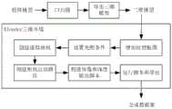
如图3所示,主要流程包括以下步骤:As shown in Figure 3, the main process includes the following steps:
1.在三维环境中导入前述的三维模型,调节模型姿态,放在合适位置;选择合适的表面纹理贴图,在“纹理”页面下将贴图赋予三维模型;1. Import the aforementioned 3D model into the 3D environment, adjust the model's posture, and place it in a suitable position; select a suitable surface texture map, and assign the map to the 3D model in the "Texture" page;
2.在“建模”页面下添加新的聚焦光源,将光源设置到环境的原点,调整光源强度参数,使光源亮度足以照亮模型腔道内,调整光源锥顶角度不小于60°;2. Add a new focused light source on the "Modeling" page, set the light source to the origin of the environment, adjust the light source intensity parameters so that the light source brightness is sufficient to illuminate the model cavity, and adjust the light source cone angle to no less than 60°;
3.在“建模”页面下添加新的相机,将相机中心与光源重合,相机的主视方向与光源方向重合,相机的上方向朝向合适位置,相机视场角设置为60°,相机焦距设置为合理大小使得图像内容与常规内镜图像相似,设置输出图像为正方形,输出分辨率为合适数字;更改相机与光源的层级关系,使光源成为相机的子一级,形成固连关系;3. Add a new camera on the "Modeling" page, make the camera center coincide with the light source, the main viewing direction of the camera coincide with the direction of the light source, the upward direction of the camera faces the appropriate position, the camera field of view is set to 60°, the camera focal length is set to a reasonable size so that the image content is similar to the conventional endoscopic image, the output image is set to a square, and the output resolution is set to an appropriate number; change the hierarchical relationship between the camera and the light source, so that the light source becomes the sub-level of the camera, forming a fixed connection relationship;
4.在“建模”页面下添加新的路径,向路径中按一定距离添加一系列三维模型腔道内的点以构成路径,设置路径为样条平滑;将前述相机对象至于路径的起始点处;在相机的“几何”属性选项卡里添加新的约束条件,添加路径约束,设置相机的主方向与路径切线方向保持重合;4. Add a new path in the "Modeling" page, add a series of points in the cavity of the 3D model to the path at a certain distance to form the path, and set the path to spline smoothing; place the aforementioned camera object at the starting point of the path; add new constraints in the "Geometry" property tab of the camera, add path constraints, and set the main direction of the camera to coincide with the tangent direction of the path;
5.导入渲染脚本,脚本中设置在动画渲染过程中读取渲染结果、图像场景的深度数据、相机参数,设置将数据按照指定格式保存至设定的输出路径,其中图像数据保存为PNG格式,深度数据保存为NPY格式,相机信息保存为TXT格式;5. Import the rendering script. In the script, set to read the rendering results, depth data of the image scene, and camera parameters during the animation rendering process. Set to save the data in the specified format to the set output path. The image data is saved in PNG format, the depth data is saved in NPY format, and the camera information is saved in TXT format.
6.在路径的“物体数据”属性下设置,设置路径帧分段数量为合适数值;在相机的“动画”属性页面下,设置相机动画的步长为1,动画帧范围在路径帧分段数范围内,以此可以控制输出数据集的数据量;在公共的“导出”属性里设置数据集输出路径、输出图片格式、分辨率等参数,并启用前述渲染脚本;6. Set the path frame segment number to an appropriate value under the "Object Data" property of the path; set the camera animation step size to 1 under the "Animation" property page of the camera, and set the animation frame range to be within the path frame segment number range, so as to control the data volume of the output data set; set the data set output path, output image format, resolution and other parameters in the public "Export" property, and enable the aforementioned rendering script;
7.运行三维软件的动画渲染功能,脚本将自动导出图像、深度、相机参数等数据,数据集构建完成。7. Run the animation rendering function of the 3D software. The script will automatically export image, depth, camera parameters and other data, and the data set construction is completed.
1.2.网络训练与应用1.2. Network training and application
本实施例使用既有的端到端UNet网络(下文称深度估计网络)进行深度估计。其中网络主干部分使用ResNet18网络。深度估计神经网络结构参见表2。This embodiment uses an existing end-to-end UNet network (hereinafter referred to as the depth estimation network) for depth estimation. The backbone of the network uses the ResNet18 network. The structure of the depth estimation neural network is shown in Table 2.
表2Table 2


注:Note:
a)k:卷积核大小,s:卷积步长大小,c:通道数量,r:分辨率因子;a) k: convolution kernel size, s: convolution step size, c: number of channels, r: resolution factor;
b)C=卷积块,B=批归一化,R18=ResNet-18;b) C = convolutional block, B = batch normalization, R18 = ResNet-18;
c)u*=2倍最近邻上采样的块,m*=残差融合输入的块。c) u* = 2x nearest neighbor upsampled block, m* = residual fusion input block.
深度估计网络输入为一帧三通道内镜图像I,通道按RGB格式存储。输入图像像素值归一化到0~1之间,要求分辨率为320×320,不符合的图像将进行剪裁和重采样操作使得符合分辨率要求。深度估计网络输出结果为与输入图像有相同分辨率的深度图D。The input of the depth estimation network is a three-channel endoscopic image I, and the channels are stored in RGB format. The pixel values of the input image are normalized to between 0 and 1, and the resolution is required to be 320×320. Images that do not meet the requirements will be cropped and resampled to meet the resolution requirements. The output of the depth estimation network is a depth map D with the same resolution as the input image.
上述深度估计方法可以概括为三维空间感知(深度估计)函数depth(·),即:The above depth estimation method can be summarized as a three-dimensional space perception (depth estimation) function depth(·), that is:
D=depth(I)D = depth (I)
上述深度估计网络使用PyTorch环境构建和训练。训练使用Adam训练器,默认训练器参数,训练循环为50,起始学习率为0.001。训练过程使用RTX2080型号的单张GPU进行。The above depth estimation network is built and trained using the PyTorch environment. The training uses the Adam trainer with default trainer parameters, 50 training cycles, and a starting learning rate of 0.001. The training process is performed using a single GPU of the RTX2080 model.
训练使用有监督方式,将深度估计网络的输出深度与数据集真值深度进行对比计算损失函数。损失函数由两部分组成:第一部分是深度值2-范数,即


2.导向路径提取2. Guide path extraction
本节描述从深度图中提取导向路径的方法。首先是对深度图D进行离散化和体素化,得到二值化的三维网格数字拓扑图


2.1.体素化2.1. Voxelization
导向路径提取的第一步是对深度图D进行体素化,获取数字拓扑图


体素化首先基于深度转换函数对深度图D进行校正。对于深度图D上的点((i,j)T,d),选择一定的离散化分辨率参数S,则定义深度转换函数为:Voxelization first corrects the depth map D based on the depth conversion function. For a point ((i, j)T , d) on the depth map D, a certain discretization resolution parameter S is selected, and the depth conversion function is defined as:

如此,得到
接着,根据数字拓扑的定义,对内点集

2.2.导向路径提取2.2. Guided path extraction
导向路径提取通过对数字拓扑图

首先,在内点集


其次,通过迭代缩减过程构建导向路径
1.创建空的已删除集


2.在扑域
3.记当前邻域方向为dir,创建空的可删除集
4.对每个拓扑域

5.对每个可删除集


6.如果已删除集
通过以上数字拓扑图缩减过程,得到了离散导向路径

2.3.路径优化2.3. Path Optimization
在本节将对离散导向路径

首先,根据深度转换函数,可以得到深度转换逆函数。对于每个离散导向路径上的点

如此,得到(i,j,d1)T∈L是深度图域D的一个点,它们构成了深度图上的导向路径LD,其中d1是经过转换的深度。Thus, (i, j, d1 )T ∈ L is a point in the depth map domain D, which constitutes the guiding pathLD on the depth map, where d1 is the transformed depth.
相机视场是一个四棱锥体空间,相机位于锥体顶部。因此,对于相同深度处对应的两个像素之间的实际距离而言,当深度越大其差异越大。这使得我们的导向路径在远距离区域更稀疏,如图5所示的深度非线性问题示意图,δ1:近端网格间距;δ2:远端网格间距,以及波动更大。The camera field of view is a quadrangular pyramid space, and the camera is located at the top of the pyramid. Therefore, for the actual distance between two pixels corresponding to the same depth, the greater the depth, the greater the difference. This makes our guidance path sparser in the long-distance area, as shown in the schematic diagram of the depth nonlinear problem in Figure 5, δ1 : near-end grid spacing; δ2 : far-end grid spacing, and the fluctuation is larger.
为了减少这种深度方向上的非线性的影响,引入如下的深度校正函数:In order to reduce the impact of this nonlinearity in the depth direction, the following depth correction function is introduced:

其中,α是校正因子,通常取1.5,d2是经过校正的深度。Where α is the correction factor, usually 1.5, andd2 is the corrected depth.
然后,根据标准针孔相机模型,可以将深度图上的导向路径LD转换到相机空间


其中,
最后,使用B样条拟合导向路径

以上,完成获取平滑导向路径l。The above is to complete the acquisition of the smooth guide path l.
3.自适应导向控制3. Adaptive Guidance Control
本节基于所提取的平滑导向路径,给出软式内镜的自主转向控制方法。具体而言,它包括运动关系映射、导向路径的微分几何信息提取、控制回路增益矩阵构建、约束参数调整等步骤和部分。This section presents an autonomous steering control method for a flexible endoscope based on the extracted smooth guide path. Specifically, it includes steps and parts such as motion relationship mapping, differential geometry information extraction of the guide path, control loop gain matrix construction, and constraint parameter adjustment.
3.1.硬件结构与运动学关系3.1. Hardware structure and kinematics relationship
软式内镜操作机构为现有技术;也可以采用一种软式内窥镜操控机器人(申请号202011370492.5),其中,本发明所涉及的X转向自由的qbx、Y转向自由的qby、输送自由度qa分别与一种软式内窥镜操控机器人(申请号202011370492.5)中所述机构的第一电机、第二电机、主动轮对应。The flexible endoscope operating mechanism is a prior art; a flexible endoscope control robot (application number 202011370492.5) may also be used, wherein the X-steering freedom qbx , Y-steering freedom qby , and conveying freedom qa involved in the present invention correspond to the first motor, the second motor, and the driving wheel of the mechanism described in a flexible endoscope control robot (application number 202011370492.5) respectively.
软式内镜操作部机构的各个驱动变量合成为驱动向量q=[qbx,qby,qa]T。q的每个驱动量被限制在[-1,1]的范围内。所有可能的q位于驱动空间

本文基于速度控制实现软式内镜的驱动控制。软式内镜驱动正运动学可表示为从驱动空间到任务空间(相机坐标系下,等价于相机空间)的映射关系

本文的J采用经验结果来实现驱动控制如下:The J in this paper adopts empirical results to realize the drive control as follows:

其中,J+是J的逆矩阵或Moore-Penrose伪逆矩阵。where J+ is the inverse or Moore-Penrose pseudoinverse of J.
3.2.微分几何信息3.2. Differential geometry information
本节从前述平滑导向路径l计算微分几何信息,以构建下一步的增益矩阵,从而确定目标速度

首先我们将平滑导向路径l转换至Frenet坐标系下的参数化方程l=l(s),其中s是弧长变量。First, we transform the smooth guide path l into a parameterized equation l=l(s) in the Frenet coordinate system, where s is the arc length variable.
第一部分微分几何信息是切向量t(s):The first part of differential geometry information is the tangent vector t(s):

第二部分微分几何信息是曲率κ(s):The second part of differential geometry information is the curvature κ(s):

本文控制方法设计目标速度大小与平均曲率关联:The control method in this paper designs the relationship between the target speed and the average curvature:

其次,目标速度方向与切方向关联。引入系数函数c=c(s),c>0,c∈[0,1],目标速度方向为:Secondly, the target velocity direction is related to the tangent direction. Introducing the coefficient function c=c(s), c>0, c∈[0,1], the target velocity direction is:

综上,省略参数s后,目标速度可表示为:In summary, after omitting the parameter s, the target speed can be expressed as:

其中,K是控制速度的增益矩阵,length(l)表示导向路径总长度,。Among them, K is the gain matrix of controlling speed, length(l) represents the total length of the guiding path,.
3.3.增益矩阵3.3. Gain matrix
本文设计增益矩阵用于调节速度响应特性,其方法为This paper designs a gain matrix to adjust the speed response characteristics, and the method is as follows:
v'=K·vv'=K·v
其中,v'为增益后的目标速度。本文将控制方案设计为两部分的方式,即多数情况下采用的常规参数Ku,以及再特殊情况下采用的条件参数Kc,并通过自适应调节参数E切换选择参数方案。Wherein, v' is the target speed after gain. This paper designs the control scheme into two parts, namely, the conventional parameterKu used in most cases, and the conditional parameterKc used in special cases, and switches the parameter scheme through the adaptive adjustment parameter E.
自适应调节参数是导向路径不同段的平均切方向的余弦差,即The adaptive adjustment parameter is the cosine difference of the average tangent direction of different segments of the guidance path, that is,

其中,L=length(l)是导向路径总长度,kc表示分段比率。Where L = length (l) is the total length of the guided path, andkc represents the segmentation ratio.
预先给定切换阈值Ec,若E不小于Ec,选用参数Ku;反正,选用Kc。A switching threshold Ec is given in advance. If E is not less than Ec , parameterKu is selected; otherwise, Kc is selected.
Ku可视为一个如下的常数矩阵:Ku can be viewed as a constant matrix as follows:

其中kbx,kby和kz表示对应自由度的基准增益系数,其中kz→∞。Where kbx , kby and kz represent the reference gain coefficients for the corresponding degrees of freedom, where kz →∞.
Kc与E关联,可表示为如下矩阵:Kc is associated with E and can be expressed as the following matrix:

其中kincx,kincy和kdec具有如下形式:where kincx , kincy , and kdec have the following forms:
kincx=kbx·(1+kG·(1-E))kincx =kbx ·(1+kG ·(1-E))
kincy=kby·(1+kG·(1-E))kincy =kby ·(1+kG ·(1-E))
kdec=ka·(1-kS·(1-E))kdec = ka ·(1-kS ·(1-E))
其中kz′是所选的不同于kz的输送增益参数,kG和kS用于确定控制的响应速度。Where kz′ is a transmission gain parameter selected to be different fromkz ,kG andkS are used to determine the response speed of the control.
3.4.约束参数3.4. Constraint Parameters
本节设计了几个额外的约束条件用于提高控制的效果:This section designs several additional constraints to improve the control effect:
1.最小曲率
2.惯量参数m用于权衡历史操作和目标操作,即v'=m·v'k-1+(1-m)·v'k,来输出平滑的控制量。2. The inertia parameter m is used to weigh the historical operation and the target operation, that is, v' = m·v'k-1 + (1-m)·v'k , to output a smooth control amount.
综上,控制输出可以表达为:In summary, the control output can be expressed as:

其中,K根据E自适应选择为Ku或者Kc。自主导航框架的总体控制方案示意图可见图6。Wherein, K is adaptively selected asKu orKc according to E. The schematic diagram of the overall control scheme of the autonomous navigation framework can be seen in FIG6 .
Claims (10)
Translated fromChinese


Priority Applications (1)
| Application Number | Priority Date | Filing Date | Title |
|---|---|---|---|
| CN202310202621.7ACN116342839B (en) | 2023-03-06 | 2023-03-06 | Autonomous guiding soft endoscope control method based on space perception |
Applications Claiming Priority (1)
| Application Number | Priority Date | Filing Date | Title |
|---|---|---|---|
| CN202310202621.7ACN116342839B (en) | 2023-03-06 | 2023-03-06 | Autonomous guiding soft endoscope control method based on space perception |
Publications (2)
| Publication Number | Publication Date |
|---|---|
| CN116342839Atrue CN116342839A (en) | 2023-06-27 |
| CN116342839B CN116342839B (en) | 2025-09-19 |
Family
ID=86878297
Family Applications (1)
| Application Number | Title | Priority Date | Filing Date |
|---|---|---|---|
| CN202310202621.7AActiveCN116342839B (en) | 2023-03-06 | 2023-03-06 | Autonomous guiding soft endoscope control method based on space perception |
Country Status (1)
| Country | Link |
|---|---|
| CN (1) | CN116342839B (en) |
Citations (13)
| Publication number | Priority date | Publication date | Assignee | Title |
|---|---|---|---|---|
| US20090048482A1 (en)* | 2007-08-14 | 2009-02-19 | Siemens Corporate Research, Inc. | Image-based Path Planning for Automated Virtual Colonoscopy Navigation |
| WO2013080131A1 (en)* | 2011-12-03 | 2013-06-06 | Koninklijke Philips Electronics N.V. | Automatic depth scrolling and orientation adjustment for semi-automated path planning |
| CN107248191A (en)* | 2017-07-06 | 2017-10-13 | 南开大学 | A kind of virtual endoscope suitable for complicated cavity is automatic and interactive route is planned and air navigation aid |
| CN110831537A (en)* | 2017-06-23 | 2020-02-21 | 奥瑞斯健康公司 | Robotic system for determining the pose of a medical device in an intraluminal network |
| CN110992431A (en)* | 2019-12-16 | 2020-04-10 | 电子科技大学 | A combined three-dimensional reconstruction method of binocular endoscopic soft tissue images |
| CN111080778A (en)* | 2019-12-23 | 2020-04-28 | 电子科技大学 | Online three-dimensional reconstruction method of binocular endoscope soft tissue image |
| CN113538335A (en)* | 2021-06-09 | 2021-10-22 | 香港中文大学深圳研究院 | In vivo relative positioning method and device for wireless capsule endoscope |
| CN114364298A (en)* | 2019-09-05 | 2022-04-15 | 奥林巴斯株式会社 | Endoscope system, processing system, working method of endoscope system, and image processing program |
| CN114399527A (en)* | 2022-01-04 | 2022-04-26 | 北京理工大学 | Method and device for unsupervised depth and motion estimation of monocular endoscope |
| US20220319031A1 (en)* | 2021-03-31 | 2022-10-06 | Auris Health, Inc. | Vision-based 6dof camera pose estimation in bronchoscopy |
| CN115294128A (en)* | 2022-10-08 | 2022-11-04 | 四川大学 | Monocular structure three-dimensional imaging method and device for digestive endoscopy |
| CN115349952A (en)* | 2022-07-04 | 2022-11-18 | 安徽医科大学第二附属医院 | A Guided 3D Virtual Fixture Generation Method for Dynamic Surgical Path Guidance |
| CN115661224A (en)* | 2022-05-26 | 2023-01-31 | 山东科技大学 | A method and device for unsupervised multi-frame endoscopic scene depth estimation |
- 2023
- 2023-03-06CNCN202310202621.7Apatent/CN116342839B/enactiveActive
Patent Citations (13)
| Publication number | Priority date | Publication date | Assignee | Title |
|---|---|---|---|---|
| US20090048482A1 (en)* | 2007-08-14 | 2009-02-19 | Siemens Corporate Research, Inc. | Image-based Path Planning for Automated Virtual Colonoscopy Navigation |
| WO2013080131A1 (en)* | 2011-12-03 | 2013-06-06 | Koninklijke Philips Electronics N.V. | Automatic depth scrolling and orientation adjustment for semi-automated path planning |
| CN110831537A (en)* | 2017-06-23 | 2020-02-21 | 奥瑞斯健康公司 | Robotic system for determining the pose of a medical device in an intraluminal network |
| CN107248191A (en)* | 2017-07-06 | 2017-10-13 | 南开大学 | A kind of virtual endoscope suitable for complicated cavity is automatic and interactive route is planned and air navigation aid |
| CN114364298A (en)* | 2019-09-05 | 2022-04-15 | 奥林巴斯株式会社 | Endoscope system, processing system, working method of endoscope system, and image processing program |
| CN110992431A (en)* | 2019-12-16 | 2020-04-10 | 电子科技大学 | A combined three-dimensional reconstruction method of binocular endoscopic soft tissue images |
| CN111080778A (en)* | 2019-12-23 | 2020-04-28 | 电子科技大学 | Online three-dimensional reconstruction method of binocular endoscope soft tissue image |
| US20220319031A1 (en)* | 2021-03-31 | 2022-10-06 | Auris Health, Inc. | Vision-based 6dof camera pose estimation in bronchoscopy |
| CN113538335A (en)* | 2021-06-09 | 2021-10-22 | 香港中文大学深圳研究院 | In vivo relative positioning method and device for wireless capsule endoscope |
| CN114399527A (en)* | 2022-01-04 | 2022-04-26 | 北京理工大学 | Method and device for unsupervised depth and motion estimation of monocular endoscope |
| CN115661224A (en)* | 2022-05-26 | 2023-01-31 | 山东科技大学 | A method and device for unsupervised multi-frame endoscopic scene depth estimation |
| CN115349952A (en)* | 2022-07-04 | 2022-11-18 | 安徽医科大学第二附属医院 | A Guided 3D Virtual Fixture Generation Method for Dynamic Surgical Path Guidance |
| CN115294128A (en)* | 2022-10-08 | 2022-11-04 | 四川大学 | Monocular structure three-dimensional imaging method and device for digestive endoscopy |
Non-Patent Citations (1)
| Title |
|---|
| JORGE F. LAZO: "Autonomous Intraluminal Navigation of a Soft Robot using Deep-Learning-based Visual Servoing", 2022 IEEE/RSJ INTERNATIONAL CONFERENCE ON INTELLIGENT ROBOTS AND SYSTEMS(IROS)), 31 December 2022 (2022-12-31), pages 6952 - 6959* |
Also Published As
| Publication number | Publication date |
|---|---|
| CN116342839B (en) | 2025-09-19 |
Similar Documents
| Publication | Publication Date | Title |
|---|---|---|
| CN109389590B (en) | Colon image data processing system and method | |
| CN110288695B (en) | Surface reconstruction method of single-frame image 3D model based on deep learning | |
| CN106023288B (en) | An Image-Based Dynamic Stand-In Construction Method | |
| CN112785609B (en) | CBCT tooth segmentation method based on deep learning | |
| CN111080778B (en) | Online three-dimensional reconstruction method of binocular endoscope soft tissue image | |
| CN109064549B (en) | Method for generating mark point detection model and method for detecting mark point | |
| CN116485851A (en) | Three-dimensional grid model registration fusion system oriented to laparoscopic surgery navigation | |
| CN102663818A (en) | Method and device for establishing three-dimensional craniomaxillofacial morphology model | |
| CN101303772A (en) | A Nonlinear 3D Face Modeling Method Based on Single Image | |
| JP7251003B2 (en) | Face mesh deformation with fine wrinkles | |
| US11403801B2 (en) | Systems and methods for building a pseudo-muscle topology of a live actor in computer animation | |
| CN101271581A (en) | Build a personalized 3D human body model | |
| CN114049464A (en) | Reconstruction method and device of three-dimensional model | |
| EP4411653A1 (en) | Systems and methods for automated rendering | |
| WO2024098240A1 (en) | Gastrointestinal endoscopy visual reconstruction navigation system and method | |
| CN116452752A (en) | Intestinal wall reconstruction method combined with monocular dense SLAM and residual network | |
| CN113808272A (en) | Texture mapping method in three-dimensional virtual human head and face modeling | |
| CN118247435A (en) | Dense 3D modeling method of intestine based on visual odometry and convolutional neural network | |
| WO2023185703A1 (en) | Motion control method, apparatus and device for virtual character, and storage medium | |
| CN117372644A (en) | Three-dimensional content generation method based on period implicit representation | |
| Taylor et al. | VR props: an end-to-end pipeline for transporting real objects into virtual and augmented environments | |
| CN113808006B (en) | Method and device for reconstructing three-dimensional grid model based on two-dimensional image | |
| CN116342839A (en) | Control method of self-guiding soft endoscope based on spatial perception | |
| Tejera et al. | Animation control of surface motion capture | |
| CN117893642B (en) | Face shape remodelling and facial feature exchanging face changing method |
Legal Events
| Date | Code | Title | Description |
|---|---|---|---|
| PB01 | Publication | ||
| PB01 | Publication | ||
| SE01 | Entry into force of request for substantive examination | ||
| SE01 | Entry into force of request for substantive examination | ||
| GR01 | Patent grant | ||
| GR01 | Patent grant |