CN116339547A - Stylus pen pressure value transmission method, electronic device and system - Google Patents
Stylus pen pressure value transmission method, electronic device and systemDownload PDFInfo
- Publication number
- CN116339547A CN116339547ACN202310626965.0ACN202310626965ACN116339547ACN 116339547 ACN116339547 ACN 116339547ACN 202310626965 ACN202310626965 ACN 202310626965ACN 116339547 ACN116339547 ACN 116339547A
- Authority
- CN
- China
- Prior art keywords
- ultrasonic signal
- pressure value
- stylus
- electronic device
- frequency
- Prior art date
- Legal status (The legal status is an assumption and is not a legal conclusion. Google has not performed a legal analysis and makes no representation as to the accuracy of the status listed.)
- Granted
Links
Images


Classifications
- G—PHYSICS
- G06—COMPUTING OR CALCULATING; COUNTING
- G06F—ELECTRIC DIGITAL DATA PROCESSING
- G06F3/00—Input arrangements for transferring data to be processed into a form capable of being handled by the computer; Output arrangements for transferring data from processing unit to output unit, e.g. interface arrangements
- G06F3/01—Input arrangements or combined input and output arrangements for interaction between user and computer
- G06F3/03—Arrangements for converting the position or the displacement of a member into a coded form
- G06F3/041—Digitisers, e.g. for touch screens or touch pads, characterised by the transducing means
- G06F3/0416—Control or interface arrangements specially adapted for digitisers
- G06F3/04162—Control or interface arrangements specially adapted for digitisers for exchanging data with external devices, e.g. smart pens, via the digitiser sensing hardware
- G—PHYSICS
- G06—COMPUTING OR CALCULATING; COUNTING
- G06F—ELECTRIC DIGITAL DATA PROCESSING
- G06F3/00—Input arrangements for transferring data to be processed into a form capable of being handled by the computer; Output arrangements for transferring data from processing unit to output unit, e.g. interface arrangements
- G06F3/01—Input arrangements or combined input and output arrangements for interaction between user and computer
- G06F3/03—Arrangements for converting the position or the displacement of a member into a coded form
- G06F3/041—Digitisers, e.g. for touch screens or touch pads, characterised by the transducing means
- G06F3/043—Digitisers, e.g. for touch screens or touch pads, characterised by the transducing means using propagating acoustic waves
- G06F3/0433—Digitisers, e.g. for touch screens or touch pads, characterised by the transducing means using propagating acoustic waves in which the acoustic waves are either generated by a movable member and propagated within a surface layer or propagated within a surface layer and captured by a movable member
Landscapes
- Engineering & Computer Science (AREA)
- General Engineering & Computer Science (AREA)
- Theoretical Computer Science (AREA)
- Physics & Mathematics (AREA)
- Human Computer Interaction (AREA)
- General Physics & Mathematics (AREA)
- Acoustics & Sound (AREA)
- Position Input By Displaying (AREA)
Abstract
Description
Translated fromChinese技术领域technical field
本申请涉及终端领域,尤其涉及一种触控笔压力值传输方法、电子设备及系统。The present application relates to the field of terminals, and in particular to a method for transmitting a pressure value of a stylus, an electronic device, and a system.
背景技术Background technique
随着终端技术的发展,电子设备在日常生活中的应用也越来越广泛。市面上有不少的电子设备(例如大屏、手机以及平板等)配备有触控笔,用户可以使用触控笔在电子设备上的触控屏进行点触、书写和擦除笔迹等操作。With the development of terminal technology, electronic devices are more and more widely used in daily life. Many electronic devices on the market (such as large screens, mobile phones, and tablets, etc.) are equipped with stylus, and users can use the stylus to perform operations such as touching, writing and erasing handwriting on the touch screen of the electronic device.
当用户使用触控笔在电子设备上书写、绘画时,触控笔主要利用蓝牙向电子设备传输压力值,使得电子设备可以基于该压力值在触控屏上显示笔迹的粗细程度。然而,通过蓝牙传输压力值的最小时间间隔依然比较长,因此,触控笔无法实时传输压力值,从而导致电子设备显示的笔迹不够精细。When a user uses a stylus to write or draw on an electronic device, the stylus mainly uses Bluetooth to transmit a pressure value to the electronic device, so that the electronic device can display the thickness of the handwriting on the touch screen based on the pressure value. However, the minimum time interval for transmitting the pressure value via Bluetooth is still relatively long, therefore, the stylus cannot transmit the pressure value in real time, resulting in insufficiently fine handwriting displayed by the electronic device.
发明内容Contents of the invention
本申请提供了一种触控笔压力值传输方法、电子设备及系统,实现了触控笔在采集到压力值后,会将压力值中的压力值转变为超声信号,并通过该超声信号向电子设备传输压力值。由于超声信号不需要按照指定的数据传输间隔发送数据信息,其调制生成后即可发送,因此不存在数据传输间隔,因此,本方法的实施可以降低触控笔发送压力值的时延,使得电子设备可以基于用户的触控操作,呈现出更精细的笔迹。同时,超声信号的传输不受电磁干扰的影响,电子设备可以获取到更精确的压力值。This application provides a pressure value transmission method, electronic equipment and system of a stylus, which realizes that after the stylus collects the pressure value, it will convert the pressure value in the pressure value into an ultrasonic signal, and transmit the ultrasonic signal to the The electronics transmit the pressure value. Since the ultrasonic signal does not need to send data information according to the specified data transmission interval, it can be sent after its modulation is generated, so there is no data transmission interval. Therefore, the implementation of this method can reduce the delay in sending the pressure value of the stylus, making the electronic The device can present finer handwriting based on the user's touch operation. At the same time, the transmission of ultrasonic signals is not affected by electromagnetic interference, and electronic equipment can obtain more accurate pressure values.
第一方面,本申请实施例提供了一种触控笔压力值传输方法,所述方法应用于包括第一触控笔和电子设备的通信系统,所述方法包括:所述第一触控笔检测到第一压力值时,发送第一频率的第一超声信号;所述电子设备接收到所述第一超声信号时,显示第一粗细度的笔迹;所述第一触控笔检测到第二压力值时,发送第二频率的第二超声信号;所述电子设备接收到所述第二超声信号时,显示第二粗细度的笔迹。In a first aspect, an embodiment of the present application provides a method for transmitting a pressure value of a stylus, the method is applied to a communication system including a first stylus and an electronic device, and the method includes: the first stylus When a first pressure value is detected, a first ultrasonic signal of a first frequency is sent; when the electronic device receives the first ultrasonic signal, it displays a handwriting of a first thickness; When the pressure value is two, a second ultrasonic signal with a second frequency is sent; when the electronic device receives the second ultrasonic signal, it displays handwriting with a second thickness.
在一种可能的实现方式中,所述电子设备接收到所述第一超声信号时,显示第一粗细度的笔迹,具体包括:所述电子设备在触控屏的第一位置接收到所述第一触控笔发送的下行信号,并接收到所述第一超声信号时,在所述第一位置显示所述第一粗细度的笔迹;所述电子设备接收到所述第二超声信号时,显示第二粗细度的笔迹,具体包括:所述电子设备在触控屏的第二位置接收到所述第一触控笔发送的下行信号,并接收到所述第二超声信号时,在所述第二位置显示所述第二粗细度的笔迹。In a possible implementation manner, when the electronic device receives the first ultrasonic signal, displaying the handwriting of the first thickness, specifically includes: the electronic device receives the first ultrasonic signal at the first position of the touch screen. When the downlink signal sent by the first stylus and the first ultrasonic signal is received, the handwriting of the first thickness is displayed at the first position; when the electronic device receives the second ultrasonic signal , displaying the handwriting of the second thickness, specifically comprising: when the electronic device receives the downlink signal sent by the first stylus at the second position of the touch screen, and receives the second ultrasonic signal, at the second position of the touch screen, The second position displays handwriting of the second thickness.
在一种可能的实现方式中,所述第一触控笔检测到第一压力值时,发送第一频率的第一超声信号,具体包括:所述第一触控笔检测到所述第一压力值时,根据第一映射关系,获取到所述第一压力值对应的第一频率;其中,所述第一映射关系用于记录多个频率和多个压力值之间的对应关系;所述第一触控笔生成所述第一频率的所述第一超声信号;所述第一触控笔发送所述第一超声信号。In a possible implementation manner, when the first stylus detects the first pressure value, sending the first ultrasonic signal of the first frequency specifically includes: the first stylus detects the first pressure value, according to the first mapping relationship, the first frequency corresponding to the first pressure value is obtained; wherein, the first mapping relationship is used to record the corresponding relationship between multiple frequencies and multiple pressure values; The first stylus generates the first ultrasonic signal of the first frequency; the first stylus sends the first ultrasonic signal.
在一种可能的实现方式中,所述第一触控笔检测到第二压力值时,发送第二频率的第二超声信号,具体包括:所述第一触控笔检测到所述第二压力值时,根据所述第一映射关系,获取到所述第二压力值对应的第二频率; 所述第一触控笔生成所述第二频率的所述第二超声信号;所述第一触控笔发送所述第二超声信号。In a possible implementation manner, when the first stylus detects the second pressure value, sending the second ultrasonic signal of the second frequency specifically includes: the first stylus detects the second pressure value When the pressure value is high, according to the first mapping relationship, the second frequency corresponding to the second pressure value is obtained; the first stylus generates the second ultrasonic signal of the second frequency; the first A stylus sends the second ultrasonic signal.
在一种可能的实现方式中,所述电子设备接收到所述第一超声信号时,显示第一粗细度的笔迹,具体包括:所述电子设备接收到所述第一超声信号时,根据所述第一映射关系,从所述第一超声信号中解析出所述第一频率对应的所述第一压力值;所述电子设备显示所述第一压力值对应的所述第一粗细度的笔迹。In a possible implementation manner, when the electronic device receives the first ultrasonic signal, displaying handwriting with a first thickness, specifically includes: when the electronic device receives the first ultrasonic signal, according to the The first mapping relationship, analyzing the first pressure value corresponding to the first frequency from the first ultrasonic signal; the electronic device displaying the first thickness corresponding to the first pressure value handwriting.
在一种可能的实现方式中,所述电子设备接收到所述第二超声信号时,显示第二粗细度的笔迹,具体包括:所述电子设备接收到所述第二超声信号时,根据所述第一映射关系,从所述第二超声信号中解析出所述第二频率对应的所述第二压力值;所述电子设备显示所述第二压力值对应的所述第二粗细度的笔迹。In a possible implementation manner, when the electronic device receives the second ultrasonic signal, displaying the handwriting of the second thickness specifically includes: when the electronic device receives the second ultrasonic signal, The first mapping relationship, analyzing the second pressure value corresponding to the second frequency from the second ultrasonic signal; the electronic device displaying the second pressure value corresponding to the second thickness handwriting.
在一种可能的实现方式中,所述电子设备接收到所述第一超声信号时,根据所述第一映射关系,从所述第一超声信号中解析出所述第一频率对应的所述第一压力值,具体包括:所述电子设备接收到所述第一超声信号和第三超声信号;其中,所述第三超声信号为第二触控笔检测到第三压力值时发出的超声信号;所述电子设备从所述第一超声信号中解析出第一标识,从所述第三超声信号中解析出第二标识;所述电子设备基于所述第一标识,确定所述第一超声信号属于所述第一触控笔;所述电子设备根据所述第一映射关系,从所述第一超声信号中解析出所述第一频率对应的所述第一压力值。In a possible implementation manner, when the electronic device receives the first ultrasonic signal, according to the first mapping relationship, it parses out the first frequency corresponding to the first ultrasonic signal from the first ultrasonic signal. The first pressure value specifically includes: the electronic device receives the first ultrasonic signal and the third ultrasonic signal; wherein the third ultrasonic signal is the ultrasonic wave emitted when the second stylus detects the third pressure value signal; the electronic device resolves the first identifier from the first ultrasonic signal, and resolves the second identifier from the third ultrasonic signal; the electronic device determines the first identifier based on the first identifier The ultrasonic signal belongs to the first stylus; the electronic device analyzes the first pressure value corresponding to the first frequency from the first ultrasonic signal according to the first mapping relationship.
第二方面,本申请实施例提供了一种触控笔,为第一触控笔,所述触控笔包括压力值检测模块和超声控制单元,其中:所述压力值检测模块用于,检测第一压力值;所述超声控制单元用于,当所述压力值检测模块检测到所述第一压力值时,发送第一频率的第一超声信号;其中,所述第一超声信号用于所述电子设备显示第一粗细度的笔迹;所述压力值检测模块还用于,检测第二压力值;所述超声控制单元还用于,当所述压力值检测模块检测到所述第二压力值时,发送第二频率的第二超声信号;其中,所述第二超声信号用于所述电子设备显示第二粗细度的笔迹。In the second aspect, the embodiment of the present application provides a stylus, which is a first stylus, and the stylus includes a pressure value detection module and an ultrasonic control unit, wherein: the pressure value detection module is used to detect A first pressure value; the ultrasonic control unit is configured to, when the pressure value detection module detects the first pressure value, send a first ultrasonic signal of a first frequency; wherein the first ultrasonic signal is used for The electronic device displays handwriting with a first thickness; the pressure value detection module is also used to detect a second pressure value; the ultrasonic control unit is also used to, when the pressure value detection module detects the second pressure value When the pressure value is higher, a second ultrasonic signal of a second frequency is sent; wherein, the second ultrasonic signal is used for the electronic device to display handwriting of a second thickness.
在一种可能的实现方式中,所述超声控制单元具体用于:当检测到所述第一压力值时,根据第一映射关系,获取到所述第一压力值对应的第一频率;其中,所述第一映射关系用于记录多个频率和多个压力值之间的对应关系;生成所述第一频率的所述第一超声信号;发送所述第一超声信号。In a possible implementation manner, the ultrasonic control unit is specifically configured to: when the first pressure value is detected, acquire the first frequency corresponding to the first pressure value according to a first mapping relationship; wherein , the first mapping relationship is used to record correspondence between multiple frequencies and multiple pressure values; generate the first ultrasonic signal of the first frequency; and send the first ultrasonic signal.
在一种可能的实现方式中,所述超声控制单元具体用于:当检测到所述第二压力值时,根据所述第一映射关系,获取到所述第二压力值对应的第二频率; 生成所述第二频率的所述第二超声信号;发送所述第二超声信号。In a possible implementation manner, the ultrasonic control unit is specifically configured to: when the second pressure value is detected, according to the first mapping relationship, acquire the second frequency corresponding to the second pressure value ; generating said second ultrasound signal at said second frequency; transmitting said second ultrasound signal.
第三方面,本申请实施例提供了一种电子设备,所述电子设备包括麦克风、音频单元和显示屏,其中:所述麦克风用于,接收触控笔发送的第一超声信号;所述音频单元用于,从所述第一超声信号中解析出第一频率对应的第一压力值;所述显示屏用于,显示所述第一压力值对应的第一粗细度的笔迹;所述麦克风还用于,接收触控笔发送的第二超声信号;所述音频单元还用于,从所述第二超声信号中解析出第二频率对应的第二压力值;所述显示屏还用于,显示所述第二压力值对应的第二粗细度的笔迹。In a third aspect, an embodiment of the present application provides an electronic device, the electronic device includes a microphone, an audio unit, and a display screen, wherein: the microphone is used to receive a first ultrasonic signal sent by a stylus; the audio unit The unit is used to analyze the first pressure value corresponding to the first frequency from the first ultrasonic signal; the display screen is used to display the handwriting of the first thickness corresponding to the first pressure value; the microphone It is also used for receiving the second ultrasonic signal sent by the stylus; the audio unit is also used for analyzing the second pressure value corresponding to the second frequency from the second ultrasonic signal; the display screen is also used for to display the handwriting of the second thickness corresponding to the second pressure value.
在一种可能的实现方式中,所述音频单元具体用于:根据第一映射关系,从所述第一超声信号中解析出所述第一频率对应的所述第一压力值;其中,所述第一映射关系用于记录多个频率和多个压力值之间的对应关系。In a possible implementation manner, the audio unit is specifically configured to: analyze the first pressure value corresponding to the first frequency from the first ultrasonic signal according to a first mapping relationship; wherein, the The first mapping relationship is used to record the corresponding relationship between multiple frequencies and multiple pressure values.
在一种可能的实现方式中,所述音频单元具体用于:根据第一映射关系,从所述第二超声信号中解析出所述第二频率对应的所述第二压力值。In a possible implementation manner, the audio unit is specifically configured to: analyze the second pressure value corresponding to the second frequency from the second ultrasonic signal according to a first mapping relationship.
在一种可能的实现方式中,所述麦克风具体用于:接收到所述第一超声信号和第三超声信号;其中,所述第三超声信号为第二触控笔检测到第三压力值时发出的超声信号;所述音频单元具体用于:从所述第一超声信号中解析出第一标识,从所述第三超声信号中解析出第二标识;基于所述第一标识,确定所述第一超声信号属于所述第一触控笔;根据所述第一映射关系,从所述第一超声信号中解析出所述第一频率对应的所述第一压力值。In a possible implementation manner, the microphone is specifically configured to: receive the first ultrasonic signal and the third ultrasonic signal; wherein the third ultrasonic signal is a third pressure value detected by the second stylus The ultrasonic signal sent at the time; the audio unit is specifically configured to: analyze the first identification from the first ultrasonic signal, and analyze the second identification from the third ultrasonic signal; based on the first identification, determine The first ultrasonic signal belongs to the first stylus; according to the first mapping relationship, the first pressure value corresponding to the first frequency is analyzed from the first ultrasonic signal.
第四方面,本申请实施例提供了一种计算机可读存储介质,所述计算机存储介质中存储有计算机程序,所述计算机程序包括可执行指令,所述可执行指令当被处理器执行时使所述处理器执行如上述任一方面任一项可能的实现方式中的方法。In a fourth aspect, the embodiment of the present application provides a computer-readable storage medium, where a computer program is stored in the computer storage medium, and the computer program includes executable instructions, and when executed by a processor, the executable instructions use The processor executes the method in any possible implementation manner of any one of the foregoing aspects.
第五方面,本申请实施例提供了一种芯片或芯片系统,包括处理电路和接口电路,所述接口电路用于接收代码指令并传输至所述处理电路,所述处理电路用于运行所述代码指令以执行如任一方面任一项可能的实现方式中的方法。In the fifth aspect, the embodiment of the present application provides a chip or a chip system, including a processing circuit and an interface circuit, the interface circuit is used to receive code instructions and transmit them to the processing circuit, and the processing circuit is used to run the Code instructions to perform the method in any possible implementation of any aspect.
附图说明Description of drawings
图1为本申请实施例提供的一种通信系统示意图;FIG. 1 is a schematic diagram of a communication system provided by an embodiment of the present application;
图2A为本申请实施例提供的一种触控笔主体结构示意图;Fig. 2A is a schematic diagram of the main body structure of a stylus provided by the embodiment of the present application;
图2B为本申请实施例提供的另一种触控笔主体结构示意图;FIG. 2B is a schematic structural diagram of another stylus body provided by the embodiment of the present application;
图2C为本申请实施例提供的一种通信系统协同示意图;FIG. 2C is a schematic diagram of a communication system collaboration provided by an embodiment of the present application;
图3为本申请实施例提供的一种笔迹显示界面示意图;Fig. 3 is a schematic diagram of a handwriting display interface provided by the embodiment of the present application;
图4A为本申请实施例提供的一种触控笔100的硬件结构示意图;FIG. 4A is a schematic diagram of a hardware structure of a
图4B为本申请实施例提供的一种电子设备200的硬件结构示意图;FIG. 4B is a schematic diagram of a hardware structure of an
图5为本申请实施例提供的一种触控笔压力值传输方法的具体流程示意图;FIG. 5 is a schematic flow chart of a method for transmitting a pressure value of a stylus provided in an embodiment of the present application;
图6为本申请实施例提供的一种触控笔压力值传输方法的总流程示意图。FIG. 6 is a schematic flowchart of a method for transmitting a pressure value of a stylus according to an embodiment of the present application.
具体实施方式Detailed ways
本申请以下实施例中所使用的术语只是为了描述特定实施例的目的,而并非旨在作为对本申请的限制。如在本申请得到说明书和所附权利要书中所使用的那样,单数表达形式“一个”、“一种”、“所述”、“上述”、“该”和“这一”也包括复数表达形式,除非其上下文中明确地有相反指示。还应当理解,本申请中使用的术语“和/或”是指包含一个或多个所列出醒目的任何或所有可能组合。在本申请实施例中,术语“第一”、“第二”仅用于描述目的,而不能理解为暗示相对重要性或者隐含指明所指示的技术特征的数量。由此,限定有“第一”、“第二”的特征可以明示或者隐含地包括一个或者更多个该特征。本申请实施例的描述中,除非另有说明,“多个”的含义是两个或两个以上。The terms used in the following embodiments of the present application are only for the purpose of describing specific embodiments, and are not intended to limit the present application. As used in the resulting specification and appended claims of this application, the singular expressions "a," "an," "said," "above," "the," and "an" include plural referents expressions, unless the context clearly indicates otherwise. It should also be understood that the term "and/or" used in this application means to include any or all possible combinations of one or more of the listed items. In the embodiments of the present application, the terms "first" and "second" are used for description purposes only, and cannot be understood as implying relative importance or implicitly indicating the quantity of indicated technical features. Thus, a feature defined as "first" and "second" may explicitly or implicitly include one or more of these features. In the description of the embodiments of the present application, unless otherwise specified, "plurality" means two or more.
图1示例性示出了本申请实施例涉及的一种通信系统。Fig. 1 exemplarily shows a communication system involved in the embodiment of the present application.
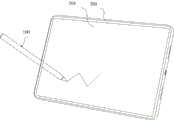
如图1所示,该通信系统可以包括:触控笔(stylus)100和电子设备200,其中:As shown in FIG. 1, the communication system may include: a stylus (stylus) 100 and an
电子设备200具有触控屏201,可以被称为用户设备(user equipment,UE)、终端(terminal)等。示例性的,电子设备200可以为平板电脑(portable android device,PAD)、个人数字处理(personal digital assistant,PDA)、具有无线通信功能的手持设备、计算设备、车载设备或可穿戴设备,虚拟现实(virtual reality,VR)终端设备、增强现实(augmented reality,AR)终端设备、工业控制(industrial control)中的无线终端、无人驾驶(self driving)中的无线终端、远程医疗(remote medical)中的无线终端、智能电网(smart grid)中的无线终端、运输安全(transportation safety)中的无线终端、智慧城市(smart city)中的无线终端、智慧家庭(smart home)中的无线终端等具有触控屏(也可以被称为触摸屏)的移动终端或固定终端。本申请实施例中,以电子设备200是平板电脑为例进行阐述。The
触控笔100可以向电子设备200提供输入。电子设备200基于触控笔100的输入,可以执行响应于该输入的操作。触控笔100和电子设备200之间可以通过通信网络进行互联,以实现无线信号的交互。该通信网络可以但不限于为:Wi-Fi热点网络、Wi-Fi点对点(peer-to-peer,P2P)网络、蓝牙网络或者zigbee网络等近距离通信网络。The
触控笔100可以但不限于为:电磁笔和电容笔。触控笔100为电磁笔时,与触控笔100交互的电子设备200的触控屏201上需要集成电磁感应板。电磁感应板上的分布有线圈,电磁笔中也集成有线圈。基于电磁感应原理,在电磁感应板所产生的磁场范围内,随着电磁笔的移动,电磁笔能够积蓄电能。电磁笔可以将积蓄的电能通过自由震荡,经电磁笔中的线圈传输至电磁感应板。电磁感应板可以基于来自电磁笔的电能,对电磁感应板上的线圈进行扫描,计算出电磁笔在触控屏201上的位置。在一种实施例中,触控屏可以称为触摸屏、屏幕或显示屏,触控笔可以称为手写笔。The
电容笔可以包括:无源电容笔和有源电容笔。无源电容笔可以称为被动式电容笔,有源电容笔可以称为主动式电容笔。Capacitive pens can include: passive capacitive pens and active capacitive pens. A passive capacitive pen can be called a passive capacitive pen, and an active capacitive pen can be called an active capacitive pen.
主动式电容笔中(例如笔尖内)可以设置一个或多个电极,主动式电容笔可以通过电极发射信号。触控笔100为主动式电容笔时,与触控笔100交互的电子设备200的触控屏201上需要集成电极阵列。在一种实施例中,电极阵列可以为电容式电极阵列。电子设备200通过电极阵列可以接收来自主动式电容笔的信号,进而在接收到该信号时,基于触控屏201上的电容值的变化识别主动式电容笔在触控屏上的位置,以及主动式电容笔的倾角。One or more electrodes can be set in the active capacitive pen (for example, inside the tip of the pen), and the active capacitive pen can transmit signals through the electrodes. When the
被动式电容笔是基于导体材料制作的具有导电特性、用来触控电子设备200的触控屏201来完成交互操作的电容笔。被动式电容笔不会主动发射信号。当被动式电容笔与电子设备200的触控屏201进行接触时,被动式电容笔基于导电特性使得触控屏201上的电流可以流经该被动式电容笔,从而改变触控屏201上的电容。电子设备200可以基于触控屏201上的电容值的变化识别该被动式电容笔在触控屏上的位置。The passive capacitive stylus is a capacitive stylus made of conductive material with conductive properties and used to touch the
需要说明的是,图1所示的通信系统仅仅用于示例性解释本申请,并不对本申请构成任何限制。It should be noted that the communication system shown in FIG. 1 is only used for exemplary explanation of the present application, and does not constitute any limitation to the present application.
图2A-图2C示例性示出了本申请实施涉及的一种触控笔100的主体结构。2A-2C schematically show the main structure of a
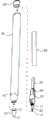
图2A为本申请实施例提供的触控笔100的结构示意图。触控笔100可以包括笔尖10、笔杆20和后盖30。笔杆20的内部为中空结构,笔尖10和后盖30分别位于笔杆20的两端,后盖30与笔杆20之间可以通过插接或者卡合方式,笔尖10与笔杆20之间的配合关系详见图2B的描述。FIG. 2A is a schematic structural diagram of the
图2B为本申请实施例提供的触控笔的部分拆分结构示意图。参照图2B所示,触控笔100还包括主轴组件50,主轴组件50位于笔杆20内,且主轴组件50在笔杆20内可滑动设置。主轴组件50上具有外螺纹51,笔尖10包括书写端11和连接端12,其中,笔尖10的连接端12具有与外螺纹51配合的内螺纹(图2B未示出)。FIG. 2B is a schematic diagram of a partially disassembled structure of the stylus provided by the embodiment of the present application. Referring to FIG. 2B , the
当主轴组件50装配到笔杆20内时,笔尖10的连接端12伸入笔杆20内且与主轴组件50的外螺纹51螺纹连接。在一些其他示例中,笔尖10的连接端12与主轴组件50之间还可以通过卡合等可拆卸方式实现连接。通过笔尖10的连接端12与主轴组件50之间可拆卸相连,这样实现了对笔尖10的更换。When the
其中,为了对笔尖10的书写端11受到的压力进行检测,参照图2A所示,笔尖10与笔杆20之间具有间隙10a,这样可以确保笔尖10的书写端11受到外力时,笔尖10可以朝向笔杆20移动,笔尖10的移动会带动主轴组件50在笔杆20内移动,而对外力的检测。参照图2B所示,在主轴组件50上设有压感组件60,压感组件60的部分与笔杆20内的固定结构固定相连,压感组件60的部分与主轴组件50固定相连。这样,主轴组件50随着笔尖10移动时,由于压感组件60的部分与笔杆20内的固定结构固定相连,所以主轴组件50的移动会驱动压感组件60形变,压感组件60的形变传递给电路板70(例如,压感组件60与电路板70之间可以通过导线或者柔性电路板实现电连接),电路板70根据压感组件60形变检测出笔尖10的书写端11的压力,从而使得电子设备200根据笔尖10书写端11的压力控制所显示出的线条的粗细。Wherein, in order to detect the pressure on the writing end 11 of the
本申请实施例中,笔尖10的压力检测包括但不限于上述方法。例如,还可以通过在笔尖10的书写端11内设置压力传感器,由压力传感器检测笔尖10的压力。在该结构中,压力传感器可以设置在触控笔100的书写端11,也可以设置在触控笔100的笔杆20内。这样,触控笔100的笔尖10一端受力后,笔尖10的另一端移动将力作用到压力传感器,从而使得压力传感器检测到触控笔100的压力值(也可以称为压感数据、压力信息)。In the embodiment of the present application, the pressure detection of the
本申请实施例中,压感组件60、压力传感器可以被称为压力值检测模块。In the embodiment of the present application, the
本实施例中,参照图2B所示,触控笔100还包括多个电极,多个电极可以为例如第一发射电极41、接地电极43和第二发射电极42。第一发射电极41、接地电极43和第二发射电极42均与电路板70电连接。第一发射电极41可以位于笔尖10内且靠近书写端11,电路板70可以被配置为可以分别向第一发射电极41和第二发射电极42提供信号的控制板,第一发射电极41用于发射第一信号,当第一发射电极41靠近电子设备200的触控屏201时,第一发射电极41与电子设备200的触控屏201之间可以形成耦合电容,这样电子设备200可以接收到第一信号。其中,第二发射电极42用于发射第二信号,电子设备200根据接收到的第二信号可以判断触控笔100的倾斜角度。本申请实施例中,第二发射电极42可以位于笔杆20的内壁上。在一种示例中,第二发射电极42也可以位于主轴组件50上。In this embodiment, as shown in FIG. 2B , the
接地电极43可以位于第一发射电极41和第二发射电极42之间,或者,接地电极43可以位于第一发射电极41和第二发射电极42的外周围,接地电极43用于降低第一发射电极41和第二发射电极42相互之间的耦合。The
当电子设备200接收来自触控笔100的第一信号时,触控屏201对应位置处的电容值会发生变化。据此,电子设备200可以基于触控屏201上的电容值的变化,确定触控笔100(或触控笔100的笔尖)在触控屏201上的位置。另外,电子设备200可以采用倾角检测算法中的双笔尖投影方法获取触控笔100的倾斜角度。其中,第一发射电极41和第二发射电极42在触控笔100中的位置不同,因此当电子设备200接收来自触控笔100的第一信号和第二信号时,触控屏201上两个位置处的电容值会发生变化。电子设备200可以根据第一发射电极41和第二发射电极42之间的距离,以及触控屏201上电容值发生变化的两个位置处之间的距离,获取触控笔100的倾斜角度。When the
本申请实施例中,参照图2B所示,触控笔100还包括:电池组件80,电池组件80用于向电路板70提供电源。其中,电池组件80可以包括锂离子电池,或者,电池组件80可以包括镍铬电池、碱性电池或镍氢电池等。在一种实施例中,电池组件80包括的电池可以为可充电电池或一次性电池,其中,当电池组件80包括的电池为可充电电池时,触控笔100可以通过无线充电方式对电池组件80中的电池进行充电。当然,也可通过有线充电方式对电池组件80中的电池进行充电,比如,在笔杆20靠近后盖30的一端设置电源连接器(图2B中未示出),电源连接器与电池组件80连接。其后盖30可遮蔽电源连接器。In the embodiment of the present application, as shown in FIG. 2B , the
其中,当触控笔100为主动式电容笔时,参照图2C,电子设备200和触控笔100无线连接后,电子设备200可以通过触控屏201上集成的电极阵列向触控笔100发送上行信号。触控笔100可以通过接收电极接收该上行信号,且触控笔100可以通过发射电极(例如第一发射电极41和第二发射电极42)发射下行信号。下行信号包括上述的第一信号和第二信号。当触控笔100的笔尖10接触触控屏201时,触控屏201对应位置处的电容值会发生变化,电子设备200可以基于触控屏201上的电容值,确定触控笔100的笔尖10在触控屏201上的位置。在一种实施例中,上行信号和下行信号可以为方波信号。Wherein, when the
当用户使用触控笔100在电子设备200的显示屏上进行书写、绘画等触控操作时,压力值检测模块可以检测到一个或多个压力值。触控笔100可以通过无线通信连接(例如,蓝牙连接等)向电子设备200发送检测到的压力值。电子设备200接收到压力值后,可以根据压力值在显示屏上显示出笔迹的粗细。When the user uses the
然而,当触控笔100通过无线通信连接发送数据时,压力值的传输会存在较长的时延,该时延一般与无线通信连接的数据传输间隔有关。例如,以蓝牙连接为例,触控笔100通过蓝牙连接发送数据信息,需要基于蓝牙协议封装数据信息,然后按照指定的数据传输间隔发送数据信息,一般的,蓝牙连接的数据传输间隔为12毫秒,也即是说蓝牙连接每隔12毫秒发送一次数据。因此,当触控笔100通过蓝牙连接发送压力值时,压力值的传输会存在12毫秒的时延,电子设备200无法及时接收到触控笔100检测到的压力值,导致笔迹的显示效果不佳。如图3所示,电子设备200在显示屏上显示出的笔迹较实际的写画笔迹更钝,笔锋效果的显示不够精细。However, when the
因此,为了解决上述问题,本申请实施例提供了一种触控笔压力值传输方法,该方法可以包括:当触控笔100在电子设备200上的显示屏进行书写、绘画等触控操作时,触控笔100可以检测到第一压力值,根据第一压力值生成第一频率的第一超声信号。触控笔100可以发送该第一超声信号。当电子设备200拾取到第一超声信号时,电子设备200可以从第一超声信号中解析出第一频率对应的第一压力值,并基于第一压力值在显示屏上显示第一粗细度的笔迹。触控笔100还可以检测到第二压力值,根据第二压力值生成第二频率的第二超声信号。触控笔100可以发送该第二超声信号。当电子设备200拾取到第二超声信号时,电子设备200可以从第二超声信号中解析出第二频率对应的第二压力值,并基于第二压力值在显示屏上显示第二粗细度的笔迹。Therefore, in order to solve the above problems, the embodiment of the present application provides a method for transmitting the pressure value of the stylus, which may include: when the
本申请实施例中,触控笔100在进行触控操作时,可以检测到多个(例如、3个、4个、5个等)压力值,触控笔100将各压力值调制成对应频率的超声信号的方式,以及电子设备200从不同频率的超声信号解析出对应压力值的方式与本申请中的记载相同。In the embodiment of the present application, the
可以看出,触控笔100在采集到压力值后,会将压力值转变为超声信号,并通过该超声信号向电子设备200传输压力值。由于超声信号不需要按照指定的数据传输间隔发送数据信息,其调制生成后即可发送,因此不存在数据传输间隔,因此,本方法的实施可以降低触控笔100发送压力值的时延,使得电子设备200可以基于用户的触控操作,呈现出更精细的笔迹。同时,超声信号的传输不受电磁干扰的影响,电子设备200可以获取到更精确的压力值。It can be seen that, after collecting the pressure value, the
图4A示例性示出了应用于本申请提供的触控笔压力值传输方法的触控笔100。FIG. 4A exemplarily shows the
如图4A所示,触控笔100可以包括:处理器110、压力值检测模块120、超声控制单元130、状态指示器140(可选的)、按钮150(可选的)、电极160、感测电路170、蓝牙模块180(可选的)和充电模块190等,其中:As shown in FIG. 4A, the
处理器110可以包括存储器和处理电路。存储器可以包括诸如非易失性存储器的存储装置(例如,闪存存储器或构造为固态驱动器的其它可编程只读存储器)、易失性存储器(例如,静态或动态随机存取存储器)等。处理器110中的处理电路可以用来控制触控笔100的操作。处理电路可以基于一个或多个微处理器、微控制器(micro controller unit,MCU)、数字信号处理器、基带处理器、电源管理单元、音频芯片、专用集成电路等构成。Processor 110 may include memory and processing circuitry. The memory may include storage devices such as non-volatile memory (eg, flash memory or other programmable read-only memory configured as a solid-state drive), volatile memory (eg, static or dynamic random access memory), and the like. Processing circuits in the processor 110 can be used to control the operation of the
压力值检测模块120可以用于检测触控笔100在电子设备200上的显示屏进行触控操作时的压力值,该压力值为施加在触控笔100的笔尖上的压力值。关于压力值检测模块120中具体的器件组成,可以参考前述说明,在此不赘述。The pressure value detection module 120 can be used to detect the pressure value of the
超声控制单元130可以用于根据压力值检测模块120检测到的压力值生成对应的超声信号,然后发送该超声信号。本申请实施例中,超声控制单元130可以设置于处理器110之外,和处理器110连接;超声控制单元130也可以集成在处理器110中,作为处理器110的一部分。The ultrasonic control unit 130 may be configured to generate a corresponding ultrasonic signal according to the pressure value detected by the pressure value detection module 120, and then send the ultrasonic signal. In the embodiment of the present application, the ultrasonic control unit 130 may be arranged outside the processor 110 and connected to the processor 110 ; the ultrasonic control unit 130 may also be integrated in the processor 110 as a part of the processor 110 .
状态指示器140为可选部件,可以用于向用户提示触控笔100的状态。The status indicator 140 is an optional component, which can be used to prompt the user the status of the
按钮150为可选部件。按钮150可以包括机械按钮和非机械按钮,按钮150可以用于从用户收集按钮按压信息。Button 150 is an optional component. Buttons 150 may include mechanical buttons and non-mechanical buttons, and buttons 150 may be used to collect button press information from a user.
触控笔100中可以包括一个或多个电极160(具体可以参照图2B中的描述),其中一个电极160可以位于触控笔100的书写端处,另一个电极160可以位于笔尖10内,具体说明可以参照上述的相关描述。The
感测电路170可以用于感测位于电极160和与触控笔100交互的电容触摸传感器面板的驱动线之间的电容耦合。感测电路170可以包括用以接收来自电容触摸传感器面板的电容读数的放大器、用以生成解调信号的时钟、用以生成相移的解调信号的相移器、用以使用同相解调频率分量来解调电容读数的混频器、以及用以使用正交解调频率分量来解调电容读数的混频器等。混频器解调的结果可用于确定与电容成比例的振幅,使得触控笔100可以感测到与电容触摸传感器面板的接触。Sensing circuitry 170 may be used to sense capacitive coupling between electrodes 160 and drive lines of a capacitive touch sensor panel that interacts with
可选的,为了支持触控笔100与电子设备200的无线通信,触控笔100可以包括无线模块。图4A中以无线模块是蓝牙模块180为例进行说明。无线模块还可以为Wi-Fi热点模块、Wi-Fi点对点模块等。蓝牙模块180可以包括射频收发器。蓝牙模块180也可以包括一个或多个天线。收发器可以利用天线发射和/或接收无线信号。Optionally, in order to support the wireless communication between the
充电模块190可以用于支持触控笔100的充电,为触控笔100提供电力。The charging module 190 can be used to support the charging of the
图4A所示的部件仅仅用于示例性解释本申请所示的触控笔100,并不应对本申请构成限制。在实际实现中,触控笔100还可以包括更多或更少的部件。The components shown in FIG. 4A are only used to illustrate the
图4B示例性示出了电子设备200的硬件结构。FIG. 4B exemplarily shows the hardware structure of the
如图4B所示,电子设备200可以包括:处理器210、输入表面220、协调引擎230、电源子系统240、电源连接器250、无线接口260(可选的)、显示器270、麦克风280和音频单元290等,其中:As shown in FIG. 4B ,
示例性的,协调引擎230可以用于与电子设备200的其他子系统进行通信和/或处理数据;与触控笔100通信和/或交易数据;测量和/或获得一个或多个模拟或数字传感器(诸如触摸传感器)的输出;测量和/或获得传感器节点阵列(诸如电容感测节点的阵列)的一个或多个传感器节点的输出;接收和定位来自触控笔100的尖端信号和环信号;基于尖端信号交叉区域和环形信号交叉区域的位置来定位触控笔100等。Exemplarily, the coordination engine 230 can be used to communicate and/or process data with other subsystems of the
电子设备200的协调引擎230可耦接至位于输入表面220下方或与该输入表面集成一体的传感器层。协调引擎230利用传感器层对输入表面220上的触控笔100进行定位,并使用本文所述的技术来估计触控笔100相对于输入表面220的平面的角位置。The coordination engine 230 of the
例如,电子设备200的协调引擎230的传感器层是布置为列和行的电容感测节点网格。更具体地说,列迹线阵列被设置成垂直于行迹线阵列。传感器层可以与电子设备的其他层分开,或者传感器层可以直接设置在另一个层上,其他层诸如但不限于:显示器叠堆层、力传感器层、数字转换器层、偏光器层、电池层、结构性或装饰性外壳层等。For example, the sensor layer of the coordination engine 230 of the
传感器层能够以多种模式操作。如果以互电容模式操作,则列迹线和行迹线在每个重叠点(例如,“垂直”互电容)处形成单个电容感测节点。如果以自电容模式操作,则列迹线和行迹线在每个重叠点处形成两个(垂直对齐的)电容感测节点。在另一个实施方案中,如果以互电容模式操作,则相邻的列迹线和/或相邻的行迹线可各自形成单个电容感测节点(例如,“水平”互电容)。如上所述,传感器层可以通过监测在每个电容感测节点处呈现的电容(例如,互电容或自电容)变化来检测触控笔100的笔尖10的存在和/或用户手指的触摸。在许多情况下,协调引擎230可被配置为经由电容耦合来检测通过传感器层从触控笔100接收的尖端信号及环信号。The sensor layer can operate in multiple modes. If operating in mutual capacitance mode, the column and row traces form a single capacitive sensing node at each point of overlap (eg, "vertical" mutual capacitance). If operating in self-capacitance mode, the column and row traces form two (vertically aligned) capacitive sensing nodes at each point of overlap. In another embodiment, adjacent column traces and/or adjacent row traces may each form a single capacitive sensing node (eg, a "horizontal" mutual capacitance) if operating in mutual capacitance mode. As described above, the sensor layer may detect the presence of the
其中,尖端信号和/或环信号可以包括可被配置为令电子设备200识别触控笔100的特定信息和/或数据。此类信息在本文通常被称为“触笔身份”信息。该信息和/或数据可以由传感器层接收,并由协调引擎230解译、解码和/或解调。Wherein, the tip signal and/or the ring signal may include specific information and/or data that may be configured to enable the
处理器210可以使用触笔身份信息来同时接收来自一支以上的触笔的输入。具体地,协调引擎230可被配置为将由协调引擎230检测到的若干触笔中的每个触笔的位置和/或角位置传输给处理器210。在其他情况下,协调引擎230还可以向处理器210传输由协调引擎230检测到的多个触笔的相对位置和/或相对角位置有关的信息。例如,协调引擎230可以通知处理器210所检测的第一触控笔位于距离所检测的第二触控笔的位置。The processor 210 may use the stylus identity information to receive input from more than one stylus at the same time. In particular, coordination engine 230 may be configured to transmit the position and/or angular position of each of the number of stylus detected by coordination engine 230 to processor 210 . In other cases, the coordination engine 230 may also transmit to the processor 210 information related to the relative positions and/or relative angular positions of the plurality of stylus detected by the coordination engine 230 . For example, the coordination engine 230 may notify the processor 210 that the detected first stylus is located at a distance from the detected second stylus.
在其他情况下,端信号和/或环信号还可以包括用于令电子设备200识别特定用户的特定信息和/或数据。此类信息在本文通常被称为“用户身份”信息。In other cases, the end signal and/or the ring signal may also include specific information and/or data for enabling the
协调引擎230可以将用户身份信息(如果检测到和/或可复原的话)转发到处理器210。如果用户身份信息不能从尖端信号和/或环信号中复原,则协调引擎230可以可选地向处理器210指示用户身份信息不可用。处理器210能够以任何合适的方式利用用户身份信息(或不存在该信息的情况),包括但不限于:接受或拒绝来自特定用户的输入,允许或拒绝访问电子设备的特定功能等。处理器210可以使用用户身份信息来同时接收来自一个以上的用户的输入。Coordination engine 230 may forward user identity information (if detected and/or recoverable) to processor 210 . If the user identity information cannot be recovered from the tip signal and/or the ring signal, the coordination engine 230 may optionally indicate to the processor 210 that the user identity information is not available. Processor 210 can utilize user identity information (or the absence of such information) in any suitable manner, including but not limited to: accepting or denying input from a specific user, allowing or denying access to specific functions of the electronic device, and the like. Processor 210 may use user identity information to receive input from more than one user at a time.
在另外的其他情况下,尖端信号和/或环信号可以包括可被配置为令电子设备200识别用户或触控笔100的设置或偏好的特定信息和/或数据。此类信息在本文通常被称为“触笔设置”信息。In still other cases, the tip signal and/or ring signal may include specific information and/or data that may be configured to cause the
协调引擎230可以将触笔设置信息(如果检测到和/或可复原的话)转发到处理器210。如果触笔设置信息不能从尖端信号和/或环信号中复原,则协调引擎230可以可选地向处理器210指示触笔设置信息不可用。电子设备200能够以任何合适的方式利用触笔设置信息(或不存在该信息的情况),包括但不限于:将设置应用于电子设备,将设置应用于在电子设备上运行的程序,改变由电子设备的图形程序所呈现的线条粗细、颜色、图案,改变在电子设备上操作的视频游戏的设置等。Coordination engine 230 may forward stylus setting information (if detected and/or recoverable) to processor 210 . If the stylus setting information cannot be recovered from the tip signal and/or the ring signal, the coordination engine 230 may optionally indicate to the processor 210 that the stylus setting information is not available. The
一般而言,处理器210可被配置为执行、协调和/或管理电子设备200的功能。此类功能可以包括但不限于:与电子设备200的其他子系统通信和/或交易数据,与触控笔100通信和/或交易数据,通过无线接口进行数据通信和/或交易数据,通过有线接口进行数据通信和/或交易数据,促进通过无线(例如,电感式、谐振式等)或有线接口进行电力交换,接收一个或多个触笔的位置和角位置等。In general, the processor 210 may be configured to perform, coordinate and/or manage the functions of the
处理器210可被实现为能够处理、接收或发送数据或指令的任何电子器件。例如,处理器可以是微处理器、中央处理单元、专用集成电路、现场可编程门阵列、数字信号处理器、模拟电路、数字电路或这些设备的组合。处理器可以是单线程或多线程处理器。处理器可以是单核或多核处理器。Processor 210 may be implemented as any electronic device capable of processing, receiving or sending data or instructions. For example, a processor may be a microprocessor, central processing unit, application specific integrated circuit, field programmable gate array, digital signal processor, analog circuit, digital circuit, or a combination of these devices. Processors can be single-threaded or multi-threaded. Processors can be single-core or multi-core processors.
在使用期间,处理器210可被配置有存储指令的存储器。该指令可被配置为使处理器执行、协调或监视电子设备200的一个或多个操作或功能。During use, processor 210 may be configured with memory that stores instructions. The instructions may be configured to cause the processor to perform, coordinate or monitor one or more operations or functions of the
存储在存储器中的指令可被配置为控制或协调电子设备200的其他部件的操作,该部件诸如但不限于:另一处理器、模拟或数字电路、易失性或非易失性存储器模块、显示器、扬声器、麦克风、旋转输入设备、按钮或其他物理输入设备、生物认证传感器和/或系统、力或触摸输入/输出部件、通信模块(诸如无线接口和/或电源连接器),和/或触觉反馈设备。The instructions stored in memory may be configured to control or coordinate the operation of other components of
存储器还可存储使用的电子数据。例如,存储器可以存储电子数据或内容(诸如媒体文件、文档和应用程序)、设备设置和偏好、定时信号和控制信号或者用于各种模块的数据、数据结构或者数据库,与检测尖端信号和/或环信号相关的文件或者配置等等。存储器可被配置为任何类型的存储器。例如,存储器可被实现作为随机存取存储器、只读存储器、闪存存储器、可移动存储器、其他类型的存储元件或此类设备的组合。The memory may also store electronic data for use. For example, memory may store electronic data or content (such as media files, documents, and applications), device settings and preferences, timing signals and control signals, or data, data structures, or databases for various modules, and detect tip signals and/or Or ring signal-related files or configurations, etc. The memory can be configured as any type of memory. For example, memory may be implemented as random access memory, read only memory, flash memory, removable memory, other types of storage elements, or a combination of such devices.
电子设备200还包括电源子系统240。电源子系统240可包括电池或其它电源。电源子系统240可被配置为向电子设备200提供电力。电源子系统240还可耦接到电源连接器250。电源连接器250可以是任何合适的连接器或端口,其可被配置为从外部电源接收电力并且/或者被配置为向外部负载提供电力。例如,在一些实施方案中,电源连接器250可以用于对电源子系统240内的电池进行再充电。在另一个实施方案中,电源连接器250可以用于将存储在(或可用于)电源子系统240内的电力传输到触控笔100。The
电子设备200还包括无线接口260,无线接口260可连接有天线,以促进电子设备200与触控笔100之间的通信。在一个实施方案中,电子设备200可被配置为经由低能量蓝牙通信接口或近场通信接口与触控笔100通信。在其他示例中,通信接口有利于电子设备200与外部通信网络、设备或平台之间的电子通信。The
无线接口260(无论是电子设备200与触控笔100之间的通信接口还是另外的通信接口)为可选部件,可被实现为一个或多个无线接口、蓝牙接口、近场通信接口、磁性接口、通用串行总线接口、电感接口、谐振接口,电容耦合接口、Wi-Fi接口、TCP/IP接口、网络通信接口、光学接口、声学接口或任何传统的通信接口。The wireless interface 260 (whether it is a communication interface between the
电子设备200还包括显示器270。显示器270可以位于输入表面220后方,或者可以与其集成一体。显示器270可以通信地耦接至处理器210。处理器210可以使用显示器270向用户呈现信息。在很多情况下,处理器210使用显示器270来呈现用户可以与之交互的界面。在许多情况下,用户操纵触控笔100与界面进行交互。在本申请实施例中,显示器270和输入表面220可以构成触控屏。The
麦克风280也可以称“话筒”,“传声器”,麦克风280可以用于拾取到超声信号。麦克风280还可以用于采集电子设备200周围环境中的声音信号,再将该声音信号转换为电信号,再将该电信号经过一系列处理,例如模数转换等,得到数字形式的音频信号。当拨打电话或发送语音信息时,用户可以通过人嘴靠近麦克风280发声,将声音信号输入到麦克风280。电子设备200可以设置至少一个麦克风280。在另一些实施例中,电子设备200可以设置两个麦克风280,除了采集声音信号,还可以实现降噪功能。在另一些实施例中,电子设备200还可以设置三个,四个或更多麦克风280,实现采集声音信号,降噪,还可以识别声音来源,实现定向录音功能等。The microphone 280 can also be called a "microphone" or a "microphone", and the microphone 280 can be used to pick up ultrasonic signals. The microphone 280 can also be used to collect sound signals in the surrounding environment of the
音频单元290可以用于解析麦克风280拾取到的超声信号,基于第一映射关系获取到超声信号频率对应的压力值,然后触发电子设备200基于该压力值通过触控屏显示出粗细不同的笔迹。本申请实施例中,音频单元290可以设置于处理器210之外,和处理器210连接;音频单元290也可以集成在处理器210中,作为处理器210的一部分。The
对于本领域的技术人员而言将显而易见的是,在适当的情况下,一些子模块可以被实现为软件或硬件。It will be apparent to those skilled in the art that some of the sub-modules may be implemented as software or hardware where appropriate.
因此,上述描述并非旨在穷举或将本公开限制于本文所述的精确形式。相反,根据上述教导内容,许多修改和变型是可能的。Accordingly, the above description is not intended to be exhaustive or to limit the disclosure to the precise forms described herein. On the contrary, many modifications and variations are possible in light of the above teachings.
下面结合图4A-图4B,说明本申请实施例提供的触控笔压力值传输方法的具体流程。The specific flow of the method for transmitting the pressure value of the stylus pen provided by the embodiment of the present application will be described below with reference to FIGS. 4A-4B .
图5示例性示出了本申请实施例提供的一种触控笔压力值传输方法的具体流程。FIG. 5 exemplarily shows a specific flow of a method for transmitting a pressure value of a stylus provided in an embodiment of the present application.
如图5所示,该方法的具体流程可以包括:As shown in Figure 5, the specific process of the method may include:
S501:压力值检测模块120检测到第一压力值。S501: The pressure value detection module 120 detects a first pressure value.
本申请实施例中,压力值检测模块120在触控笔100的笔尖10受到外界施加的压力时,可以将该压力转变为连续输出的模拟信号(例如,电压信号或电流信号),然后,压力值检测模块120可以通过模数转换器(analog-to-digital converter,ADC)将连续的模拟信号进行采样、量化等处理,将其转变为能够被触控笔100中处理器110、超声控制单元130所识别、处理的离散的数字信号。In the embodiment of the present application, when the
触控笔100的压力精度等级可以为256级、1024级或4096级等等。不同的压力精度等级,表征触控笔100检测施加在笔尖10上压力的能力。例如,当触控笔100的压力精度等级为256级时,触控笔100可以检测到256个不同的压力值;当触控笔100的压力精度等级为1024级时,触控笔100可以检测到1024个不同的压力值;触控笔100的压力精度等级为4096级时,触控笔100可以检测到4096个不同的压力值。响应于不同的压力值,电子设备200可以在显示屏上显示出粗细不同的笔迹。The pressure accuracy level of the
本申请实施例中,在压力值检测模块120检测第一压力值之前,为了使得电子设备200可以接收到触控笔100发送的数据信息,电子设备200需要与触控笔100同步。具体的,电子设备200可以向触控笔100发送上行信号。当触控笔100接收到电子设备200的上行信号之后,触控笔100可以和电子设备200同步,电子设备200可以接收到触控笔100发送的数据信息,从而实现绘画、书写等功能。In the embodiment of the present application, before the pressure value detection module 120 detects the first pressure value, in order for the
S502:压力值检测模块120将第一压力值发送给处理器110。S502: The pressure value detection module 120 sends the first pressure value to the processor 110.
S503:处理器110将第一压力值发送给超声控制单元130。S503: The processor 110 sends the first pressure value to the ultrasound control unit 130.
S504:超声控制单元130将第一压力值映射为对应的第一频率。S504: The ultrasound control unit 130 maps the first pressure value to a corresponding first frequency.
本申请实施例中,超声控制单元130可以预先存储有各压力值和不同频率之间的映射关系(也即第一映射关系)。超声控制单元130可以基于该第一映射关系,将接收到的第一压力值映射为对应的第一频率。In the embodiment of the present application, the ultrasound control unit 130 may pre-store the mapping relationship between each pressure value and different frequencies (that is, the first mapping relationship). The ultrasound control unit 130 may map the received first pressure value to a corresponding first frequency based on the first mapping relationship.
示例性的,第一映射关系可以通过表格的形式存储在超声控制单元130中。各压力值和不同的频率之间的映射关系可以如下述表1所示:Exemplarily, the first mapping relationship may be stored in the ultrasound control unit 130 in the form of a table. The mapping relationship between each pressure value and different frequencies can be shown in Table 1 below:
表1Table 1

从表1可以看出,不同的压力值对应不同的频率。例如,当压力值为1时,对应的频率可以是21KHz;当压力值为2时,对应的频率可以是22KHz;当压力值为3时,对应的频率可以是23KHz;当压力值为4时,对应的频率可以是24KHz等等。It can be seen from Table 1 that different pressure values correspond to different frequencies. For example, when the pressure value is 1, the corresponding frequency can be 21KHz; when the pressure value is 2, the corresponding frequency can be 22KHz; when the pressure value is 3, the corresponding frequency can be 23KHz; when the pressure value is 4 , the corresponding frequency can be 24KHz and so on.
本申请实施例中,表1仅仅用于示例性解释本申请,并不对本申请构成限制。在实际实现中,各压力值和不同的频率之间的映射关系也可以不同于表1。In the embodiment of the present application, Table 1 is only used for exemplary explanation of the present application, and does not constitute a limitation to the present application. In actual implementation, the mapping relationship between each pressure value and different frequencies may also be different from Table 1.
S505:超声控制单元130生成第一频率的第一超声信号。S505: The ultrasound control unit 130 generates a first ultrasound signal of a first frequency.
S506:电子设备200中的麦克风280拾取到超声控制单元130发送的第一超声信号。S506: The microphone 280 in the
本申请实施例中,超声信号的频率超过了人耳可以听见的频率范围(例如,20Hz~20KHz)。当超声控制单元130生成第一超声信号后,超声控制单元130可以发送第一超声信号。该第一超声信号的频率超过人耳能够听见的频率,因此,电子设备200中的麦克风280可以拾取到第一超声信号,而人耳无法感知。In the embodiment of the present application, the frequency of the ultrasonic signal exceeds the audible frequency range of the human ear (for example, 20 Hz-20 KHz). After the ultrasonic control unit 130 generates the first ultrasonic signal, the ultrasonic control unit 130 may send the first ultrasonic signal. The frequency of the first ultrasonic signal exceeds the frequency that can be heard by the human ear. Therefore, the microphone 280 in the
S507:麦克风280将第一超声信号发送给音频单元290。S507: The microphone 280 sends the first ultrasonic signal to the
具体的,麦克风280可以仅拾取并发送触控笔100发送的超声信号(例如,本步骤中的第一超声信号、后文中的第二超声信号)。Specifically, the microphone 280 may only pick up and send the ultrasonic signal sent by the stylus 100 (for example, the first ultrasonic signal in this step, and the second ultrasonic signal in the following).
进一步的,麦克风280除了拾取到触控笔100发出的超声信号之外,还可以拾取到其他声音信号。麦克风280将触控笔100发出的超声信号、其他声音信号发送给音频单元290。该“其他声音信号”的类型可以是:人耳可听频率之内的噪声、其他触控笔(例如,触控笔300)发出的超声信号等。针对该情况的处理,后续实施例将展开描述。Further, the microphone 280 can pick up other sound signals besides the ultrasonic signal sent by the
S508:音频单元290可以从第一超声信号中解析出第一频率对应的第一压力值。S508: The
音频单元290可以预先存储有多个频率和多个压力值之间的映射关系(即第一映射关系)。例如,该第一映射关系中记录第一压力值对应第一频率、第二压力值对应第二频率等。音频单元290可以根据该第一映射关系,从第一超声信号中解析出第一频率对应的第一压力值。示例性的,第一映射关系可以通过表格的形式存储在音频单元290中。各压力值和不同的频率之间的映射关系可以如上述表1所示,具体说明可以参考前述说明,在此不赘述。The
S509: 音频单元290根据第一压力值,触发显示屏显示出第一粗细度的笔迹。S509: The
本申请实施例中,当电子设备200中的电极阵列在触控屏的第一位置接收到触控笔100发送的下行信号,并通过麦克风280接收、音频单元290解析出第一超声信号时,电子设备200可以在触控屏的第一位置上显示第一压力值对应的第一粗细度的笔迹。音频单元290解析第一超声信号的方式可以参考S508的说明。In the embodiment of the present application, when the electrode array in the
本申请实施例中,不同的压力值可以对应不同粗细的笔迹。例如,当压力值为5时,电子设备200可以在显示屏上显示出极细的笔迹。当压力值为1105时,电子设备200可以在显示屏上显示出较粗的笔迹。电子设备200可以根据压力值的数值大小,在显示屏上显示出对应粗细的笔迹。In the embodiment of the present application, different pressure values may correspond to handwritings of different thicknesses. For example, when the pressure value is 5, the
S510:压力值检测模块120检测到第二压力值。S510: The pressure value detection module 120 detects a second pressure value.
该步骤的说明可以参考前述S501的描述,在此不赘述。For the description of this step, reference may be made to the description of S501 above, and details are not repeated here.
S511:压力值检测模块120将第二压力值发送给处理器110。S511: The pressure value detection module 120 sends the second pressure value to the processor 110.
该步骤的说明可以参考前述S502的描述,在此不赘述。For the description of this step, reference may be made to the description of S502 above, and details are not repeated here.
S512:处理器110将第二压力值发送给超声控制单元130。S512: The processor 110 sends the second pressure value to the ultrasound control unit 130.
该步骤的说明可以参考前述S503的描述,在此不赘述。For the description of this step, reference may be made to the foregoing description of S503 , and details are not repeated here.
S513:超声控制单元130将第二压力值映射为对应的第二频率。S513: The ultrasonic control unit 130 maps the second pressure value to a corresponding second frequency.
该步骤的说明可以参考前述S504的描述,在此不赘述。For the description of this step, reference may be made to the description of S504 above, and details are not repeated here.
S514:超声控制单元130生成第二频率的第二超声信号。S514: The ultrasound control unit 130 generates a second ultrasound signal of a second frequency.
该步骤的说明可以参考前述S505的描述,在此不赘述。For the description of this step, reference may be made to the description of the aforementioned S505, and details are not repeated here.
S515:电子设备200中的麦克风280拾取到超声控制单元130发送的第二超声信号。S515: The microphone 280 in the
该步骤的说明可以参考前述S506的描述,在此不赘述。For the description of this step, reference may be made to the description of the aforementioned S506, and details are not repeated here.
S516:麦克风280将第二超声信号发送给音频单元290。S516: The microphone 280 sends the second ultrasonic signal to the
该步骤的说明可以参考前述S507的描述,在此不赘述。For the description of this step, reference may be made to the description of S507 above, and details are not repeated here.
S517:音频单元290可以从第二超声信号中解析出第二频率对应的第二压力值。S517: The
该步骤的说明可以参考前述S508的描述,在此不赘述。For the description of this step, reference may be made to the description of S508 above, and details are not repeated here.
S518:音频单元290根据第二压力值,触发显示屏显示出第二粗细度的笔迹。S518: The
本申请实施例中,当电子设备200中的电极阵列在触控屏的第二位置接收到触控笔100发送的下行信号,并通过麦克风280接收、音频单元290解析出第二超声信号时,电子设备200可以在触控屏的第二位置上显示第二粗细度的笔迹。音频单元290解析第二超声信号的方式和解析第一超声信号的方式相同。In the embodiment of the present application, when the electrode array in the
该步骤的说明可以参考前述S509的描述,在此不赘述。For the description of this step, reference may be made to the description of the foregoing S509, and details are not repeated here.
进一步的,若麦克风280可以拾取到触控笔100发送的超声信号(例如,第一超声信号、第二超声信号等)和其他声音信号时,麦克风280和/或音频单元290需要先提取出触控笔100发送的超声信号,音频单元290再对触控笔100发送的超声信号进行解析。下面以触控笔100发出第一超声信号为例,根据其他声音信号的类型不同,提取出触控笔100发送的超声信号的实现方式可以有以下几种场景:Furthermore, if the microphone 280 can pick up the ultrasonic signal (for example, the first ultrasonic signal, the second ultrasonic signal, etc.) and other sound signals sent by the
场景一:麦克风280拾取到第一超声信号和人耳可听频率之内的噪声。Scenario 1: The microphone 280 picks up the first ultrasonic signal and noise within the frequency audible to the human ear.
该场景下,麦克风280/音频单元290可以通过高通滤波器将人耳可听频率之内的噪声滤除,获取到干净的第一超声信号。当音频单元290获取到干净的第一超声信号时,音频单元290从第一超声信号解析出第一频率对应的第一压力值。In this scenario, the microphone 280/
场景二:麦克风280拾取到第一超声信号和触控笔300发出的超声信号。Scenario 2: The microphone 280 picks up the first ultrasonic signal and the ultrasonic signal sent by the stylus 300 .
在场景二中,又可以细分为两个情景:In the second scenario, it can be subdivided into two scenarios:
A).情景一:触控笔100(可称为第一触控笔)和触控笔300(可称为第二触控笔)都用于电子设备200的触控操作。A). Scenario 1: Both the stylus 100 (which may be called the first stylus) and the stylus 300 (which may be called the second stylus) are used for the touch operation of the
本申请实施例中,触控笔100发出的超声信号的波形,可以和触控笔300发出的超声信号的波形不同。电子设备200中的麦克风280或音频单元290可以通过超声信号的波形,确定各超声信号对应的触控笔。音频单元290解析出各超声信号对应的压力值,然后触发电子设备200上的显示屏在各触控笔点触的位置上,显示各触控笔相关压力值所对应的笔迹。In the embodiment of the present application, the waveform of the ultrasonic signal sent by the
示例性的,触控笔100检测到第一压力值时,基于第一压力值调制并发出第一频率的第一超声信号。触控笔300检测到第三压力值时,基于第三压力值调制并发出第三频率的第三超声信号。触控笔100发出的第一超声信号的波形可以是正弦波,触控笔300发出的第三超声信号的波形可以是方波。麦克风280接收到两路超声信号时,麦克风280或者音频单元290确定正弦波波形的第一超声信号对应触控笔100,方波波形的第三超声信号对应触控笔300。音频单元290从第一超声信号解析出第一压力值时,触发电子设备200上的显示屏在触控笔100点触的位置上显示出第一压力值对应的第一粗细度的笔迹;音频单元290从第三超声信号解析出第三压力值时,触发电子设备200上的显示屏在触控笔100点触的位置上显示出第三压力值对应的第三粗细度的笔迹。关于触控笔300基于第三压力值调制出第三超声信号的方式,以及音频单元290从第三超声信号解析出第三压力值的方式,可以参考本申请图5所示实施例的相关描述。Exemplarily, when the
B).情景二:触控笔100用于电子设备200的触控操作,触控笔300用于电子设备400的触控操作。B). Scenario 2: The
本申请实施例中,麦克风280/音频单元290可以通过相关分析算法、麦克风声阵列定位技术计算出触控笔100和触控笔300相对于电子设备200的距离,以及触控笔100对应的超声信号、触控笔300对应的超声信号。当触控笔300相较于电子设备200的距离大于指定阈值时,音频单元290确定触控笔300不适用于电子设备200的触控操作,因此音频单元290解析触控笔100发出的超声信号对应的压力值,然后触发电子设备200上的显示屏在触控笔100点触的位置上显示出该压力值对应的笔迹。In the embodiment of the present application, the microphone 280/
示例性的,触控笔100检测到第一压力值时,基于第一压力值调制并发出第一频率的第一超声信号。触控笔300检测到第三压力值时,基于第三压力值调制并发出第三频率的第三超声信号。麦克风280可以拾取到第一超声信号和第三超声信号。麦克风280或音频单元290可以通过相关分析算法、麦克风声阵列定位技术确定出触控笔100在电子设备200上显示屏的具体位置、触控笔300相较于电子设备200的距离,以及触控笔100对应第一超声信号、触控笔300对应第三超声信号。当触控笔300相较于电子设备200的距离大于指定阈值时,音频单元290确定触控笔300不适用于电子设备200的触控操作,因此,音频单元290不必解析第三超声信号,而是从第一超声信号解析出第一压力值,然后触发电子设备200上的显示屏在触控笔100点触的位置上显示出第一压力值对应的第一粗细度的笔迹。Exemplarily, when the
本申请实施例中,触控笔100、触控笔300还可以将各自的设备标识调制到超声信号上。各触控笔的设备标识与自身发射的第一信号(TX1)、第二信号(TX2)呈线性相关。这样,当麦克风280接收到两路超声信号时,音频单元290可以从各超声信号中解析出设备标识,确定哪一路超声信号属于触控笔100,继而从触控笔100发送的超声信号中解析出压力值,触发电子设备200上的显示屏在触控笔100点触的位置上显示出该压力值对应的笔迹。In the embodiment of the present application, the
示例性的,触控笔100的设备标识为第一标识,与触控笔100发射的第一信号(TX1)、第二信号(TX2)呈线性相关;触控笔300的设备标识为第二标识,与触控笔300发射的第一信号(TX1)、第二信号(TX2)呈线性相关。第一标识和第二标识不相同。触控笔100检测到第一压力值时,基于第一压力值调制第一频率的第一超声信号,同时将第一标识调制到第一超声信号上。触控笔300检测到第三压力值时,基于第三压力值调制第三频率的第三超声信号,同时将第二标识调制到第三超声信号上。当麦克风280接收并将第一超声信号和第三超声信号发送给音频单元290时,音频单元290可以从第一超声信号中解析出第一标识,从第三超声信号中解析出第二标识。音频单元290基于第一标识确定第一超声信号属于触控笔100,继而从第一超声信号中解析出第一压力值,触发电子设备200上的显示屏在触控笔100点触的位置上显示出第一压力值对应的第一粗细度的笔迹。Exemplarily, the device identification of the
场景三:麦克风280拾取到第一超声信号和超声信号频段之内的噪声。Scenario 3: The microphone 280 picks up the first ultrasonic signal and noise within the frequency band of the ultrasonic signal.
在自然情况下,超声信号频段(例如,大于20KHz)之内的噪声不具有声音信号的特征,因此,不干扰音频单元290解析触控笔100发出的超声信号。音频单元290可以参考图5所示实施例执行相应流程。Under natural circumstances, the noise within the ultrasound signal frequency band (for example, greater than 20 KHz) does not have the characteristics of the sound signal, therefore, it does not interfere with the
本申请实施例中,场景一、二、三中涉及到基于压力值调制超声信号的方式,以及从超声信号中解析出压力值的方式,可参考图5所示实施例中的描述。触控笔300的硬件结构和触控笔100的硬件结构相同。In the embodiment of the present application,
本申请实施例中,触控笔300、电子设备400仅作文字示例说明,图1~图6没有示出。In the embodiment of the present application, the stylus 300 and the electronic device 400 are only described as examples in words, and are not shown in FIGS. 1 to 6 .
图6示例性示出了本申请实施例提供的一种触控笔压力值传输方法的总流程。FIG. 6 exemplarily shows a general flow of a method for transmitting a pressure value of a stylus provided by an embodiment of the present application.
如图6所示,该总流程可以包括:As shown in Figure 6, the overall process may include:
S601:触控笔100检测到第一压力值。S601: The
该步骤的说明可以参考S501的描述,在此不赘述。For the description of this step, reference may be made to the description of S501, and details are not repeated here.
S602:触控笔100发送第一频率的第一超声信号。S602: The
具体的,触控笔100检测到第一压力值时,可以根据第一映射关系,获取到第一压力值对应的第一频率。然后,触控笔100生成第一频率的第一超声信号,继而发送第一超声信号。其中,第一映射关系用于记录多个频率和多个压力值之间的对应关系。Specifically, when the
详细描述可以参考S502~S506的说明,在此不赘述。For a detailed description, reference may be made to descriptions of S502 to S506 , and details are not repeated here.
S603:当电子设备200接收到第一超声信号,电子设备200显示第一粗细度的笔迹。S603: When the
具体的,当电子设备200在触控屏的第一位置接收到触控笔100发送的下行信号,并接收到第一超声信号时,电子设备200根据第一映射关系,从第一超声信号中解析出第一频率对应的第一压力值,然后,电子设备200可以在触控屏的第一位置显示第一压力值对应的第一粗细度的笔迹。Specifically, when the
详细说明可以参考S507~S509的描述,在此不赘述。For detailed description, reference may be made to the description of S507-S509, which will not be repeated here.
S604:触控笔100检测到第二压力值。S604: The
该步骤的说明可以参考S510的描述,在此不赘述。For the description of this step, reference may be made to the description of S510, and details are not repeated here.
S605:触控笔100发送第二频率的第二超声信号。S605: The
具体的,触控笔100检测到第二压力值时,可以根据第一映射关系,获取到第二压力值对应的第二频率。然后,触控笔100生成第二频率的第二超声信号,继而发送第二超声信号。Specifically, when the
详细描述可以参考S511~S515的说明,在此不赘述。For a detailed description, reference may be made to descriptions of S511 to S515 , and details are not repeated here.
S606:当电子设备200接收到第二超声信号时,电子设备200显示第二粗细度的笔迹。S606: When the
具体的,当电子设备200在触控屏的第二位置接收到触控笔100发送的下行信号,并接收到第二超声信号时,电子设备200根据第一映射关系,从第二超声信号中解析出第二频率对应的第二压力值,然后,电子设备200可以在触控屏的第二位置显示第二压力值对应的第二粗细度的笔迹。Specifically, when the
详细说明可以参考S516~S518的描述,在此不赘述。For a detailed description, reference may be made to the description of S516-S518, which will not be repeated here.
上述实施例中所用,根据上下文,术语“当…时”可以被解释为意思是“如果…”或“在…后”或“响应于确定…”或“响应于检测到…”。类似地,根据上下文,短语“在确定…时”或“如果检测到(所陈述的条件或事件)”可以被解释为意思是“如果确定…”或“响应于确定…”或“在检测到(所陈述的条件或事件)时”或“响应于检测到(所陈述的条件或事件)”。As used in the above embodiments, depending on the context, the term "when" may be interpreted to mean "if" or "after" or "in response to determining..." or "in response to detecting...". Similarly, depending on the context, the phrases "in determining" or "if detected (a stated condition or event)" may be interpreted to mean "if determining..." or "in response to determining..." or "on detecting (a stated condition or event)" or "in response to the detection of (a stated condition or event)".
在上述实施例中,可以全部或部分地通过软件、硬件、固件或者其任意组合来实现。当使用软件实现时,可以全部或部分地以计算机程序产品的形式实现。所述计算机程序产品包括一个或多个计算机指令。在计算机上加载和执行所述计算机程序指令时,全部或部分地产生按照本申请实施例所述的流程或功能。所述计算机可以是通用计算机、专用计算机、计算机网络、或者其他可编程装置。所述计算机指令可以存储在计算机可读存储介质中,或者从一个计算机可读存储介质向另一个计算机可读存储介质传输,例如,所述计算机指令可以从一个网站站点、计算机、服务器或数据中心通过有线(例如同轴电缆、光纤、数字用户线)或无线(例如红外、无线、微波等)方式向另一个网站站点、计算机、服务器或数据中心进行传输。所述计算机可读存储介质可以是计算机能够存取的任何可用介质或者是包含一个或多个可用介质集成的服务器、数据中心等数据存储设备。所述可用介质可以是磁性介质,(例如,软盘、硬盘、磁带)、光介质(例如DVD)、或者半导体介质(例如固态硬盘)等。In the above embodiments, all or part of them may be implemented by software, hardware, firmware or any combination thereof. When implemented using software, it may be implemented in whole or in part in the form of a computer program product. The computer program product includes one or more computer instructions. When the computer program instructions are loaded and executed on the computer, the processes or functions according to the embodiments of the present application will be generated in whole or in part. The computer can be a general purpose computer, a special purpose computer, a computer network, or other programmable devices. The computer instructions may be stored in or transmitted from one computer-readable storage medium to another computer-readable storage medium, for example, the computer instructions may be transmitted from a website, computer, server or data center Transmission to another website site, computer, server, or data center by wired (eg, coaxial cable, optical fiber, DSL) or wireless (eg, infrared, wireless, microwave, etc.) means. The computer-readable storage medium may be any available medium that can be accessed by a computer, or a data storage device such as a server or a data center integrated with one or more available media. The available medium may be a magnetic medium (for example, a floppy disk, a hard disk, or a magnetic tape), an optical medium (for example, DVD), or a semiconductor medium (for example, a solid-state hard disk), and the like.
本领域普通技术人员可以理解实现上述实施例方法中的全部或部分流程,该流程可以由计算机程序来指令相关的硬件完成,该程序可存储于计算机可读取存储介质中,该程序在执行时,可包括如上述各方法实施例的流程。而前述的存储介质包括:ROM或随机存储记忆体RAM、磁碟或者光盘等各种可存储程序代码的介质。Those of ordinary skill in the art can understand that all or part of the processes in the methods of the above embodiments are realized. The processes can be completed by computer programs to instruct related hardware. The programs can be stored in computer-readable storage media. When the programs are executed , may include the processes of the foregoing method embodiments. The aforementioned storage medium includes: ROM or random access memory RAM, magnetic disk or optical disk, and other various media that can store program codes.
Claims (16)
Translated fromChinesePriority Applications (1)
| Application Number | Priority Date | Filing Date | Title |
|---|---|---|---|
| CN202310626965.0ACN116339547B (en) | 2023-05-31 | 2023-05-31 | Touch pen pressure value transmission method, electronic equipment and system |
Applications Claiming Priority (1)
| Application Number | Priority Date | Filing Date | Title |
|---|---|---|---|
| CN202310626965.0ACN116339547B (en) | 2023-05-31 | 2023-05-31 | Touch pen pressure value transmission method, electronic equipment and system |
Publications (2)
| Publication Number | Publication Date |
|---|---|
| CN116339547Atrue CN116339547A (en) | 2023-06-27 |
| CN116339547B CN116339547B (en) | 2024-06-21 |
Family
ID=86880859
Family Applications (1)
| Application Number | Title | Priority Date | Filing Date |
|---|---|---|---|
| CN202310626965.0AActiveCN116339547B (en) | 2023-05-31 | 2023-05-31 | Touch pen pressure value transmission method, electronic equipment and system |
Country Status (1)
| Country | Link |
|---|---|
| CN (1) | CN116339547B (en) |
Citations (5)
| Publication number | Priority date | Publication date | Assignee | Title |
|---|---|---|---|---|
| US6628271B1 (en)* | 1999-11-15 | 2003-09-30 | Pioneer Corporation | Touch panel device |
| JP2004164505A (en)* | 2002-11-15 | 2004-06-10 | Fujitsu Ltd | Coordinate output device |
| JP2010191783A (en)* | 2009-02-19 | 2010-09-02 | Nec Corp | Electronic pen and electronic pen system |
| CN102207801A (en)* | 2011-04-15 | 2011-10-05 | 深圳市华测检测技术股份有限公司 | Three-dimensional hand-writing input device and hand-writing input method |
| CN206684693U (en)* | 2017-04-18 | 2017-11-28 | 成都吉锐时代触摸技术有限公司 | A kind of ultrasonic pen of variable transmission frequency |
- 2023
- 2023-05-31CNCN202310626965.0Apatent/CN116339547B/enactiveActive
Patent Citations (5)
| Publication number | Priority date | Publication date | Assignee | Title |
|---|---|---|---|---|
| US6628271B1 (en)* | 1999-11-15 | 2003-09-30 | Pioneer Corporation | Touch panel device |
| JP2004164505A (en)* | 2002-11-15 | 2004-06-10 | Fujitsu Ltd | Coordinate output device |
| JP2010191783A (en)* | 2009-02-19 | 2010-09-02 | Nec Corp | Electronic pen and electronic pen system |
| CN102207801A (en)* | 2011-04-15 | 2011-10-05 | 深圳市华测检测技术股份有限公司 | Three-dimensional hand-writing input device and hand-writing input method |
| CN206684693U (en)* | 2017-04-18 | 2017-11-28 | 成都吉锐时代触摸技术有限公司 | A kind of ultrasonic pen of variable transmission frequency |
Also Published As
| Publication number | Publication date |
|---|---|
| CN116339547B (en) | 2024-06-21 |
Similar Documents
| Publication | Publication Date | Title |
|---|---|---|
| CN113268172B (en) | Stylus and Electronic Device Components | |
| CN113490158B (en) | Bluetooth device pairing connection method, electronic device, Bluetooth device and terminal system | |
| JP6942296B2 (en) | Truth handwriting touch pen and touch device | |
| CN113885716B (en) | Stylus and Electronic Device Components | |
| CN116466867B (en) | Handwriting drawing method and device, electronic equipment and readable storage medium | |
| US11490223B2 (en) | Method and electronic device for providing notification based on distance of remote input device | |
| CN114465366B (en) | Wireless charging method and electronic equipment | |
| CN115562560B (en) | Handwriting drawing method, device, electronic device and readable storage medium | |
| US20240411390A1 (en) | Function Mode Switching Method, Electronic Device, and System | |
| CN114995665A (en) | Tip life prompting method of stylus, stylus and electronic device | |
| CN114911364A (en) | Control method, touch pen and touch system | |
| CN116339547B (en) | Touch pen pressure value transmission method, electronic equipment and system | |
| CN116088695B (en) | System upgrading method and related device | |
| CN115543105B (en) | Information transmission method and device | |
| CN114461092B (en) | A kind of connecting method of touch pen and electronic device | |
| CN116736989B (en) | Touch pen and control method thereof | |
| CN116736988B (en) | Stylus pen tip detection method, electronic device and system | |
| HK40068786B (en) | Method for connecting stylus pen and electronic device |
Legal Events
| Date | Code | Title | Description |
|---|---|---|---|
| PB01 | Publication | ||
| PB01 | Publication | ||
| SE01 | Entry into force of request for substantive examination | ||
| SE01 | Entry into force of request for substantive examination | ||
| GR01 | Patent grant | ||
| GR01 | Patent grant | ||
| CP03 | Change of name, title or address | Address after:Unit 3401, unit a, building 6, Shenye Zhongcheng, No. 8089, Hongli West Road, Donghai community, Xiangmihu street, Futian District, Shenzhen, Guangdong 518040 Patentee after:Honor Terminal Co.,Ltd. Country or region after:China Address before:3401, unit a, building 6, Shenye Zhongcheng, No. 8089, Hongli West Road, Donghai community, Xiangmihu street, Futian District, Shenzhen, Guangdong Patentee before:Honor Device Co.,Ltd. Country or region before:China | |
| CP03 | Change of name, title or address |