CN116338228A - A speed sensor and its manufacturing method - Google Patents
A speed sensor and its manufacturing methodDownload PDFInfo
- Publication number
- CN116338228A CN116338228ACN202111603914.3ACN202111603914ACN116338228ACN 116338228 ACN116338228 ACN 116338228ACN 202111603914 ACN202111603914 ACN 202111603914ACN 116338228 ACN116338228 ACN 116338228A
- Authority
- CN
- China
- Prior art keywords
- flange
- speed sensor
- petal
- sensor according
- manufacturing
- Prior art date
- Legal status (The legal status is an assumption and is not a legal conclusion. Google has not performed a legal analysis and makes no representation as to the accuracy of the status listed.)
- Pending
Links
Images


Classifications
- G—PHYSICS
- G01—MEASURING; TESTING
- G01P—MEASURING LINEAR OR ANGULAR SPEED, ACCELERATION, DECELERATION, OR SHOCK; INDICATING PRESENCE, ABSENCE, OR DIRECTION, OF MOVEMENT
- G01P1/00—Details of instruments
- G01P1/02—Housings
- G01P1/026—Housings for speed measuring devices, e.g. pulse generator
- G—PHYSICS
- G01—MEASURING; TESTING
- G01P—MEASURING LINEAR OR ANGULAR SPEED, ACCELERATION, DECELERATION, OR SHOCK; INDICATING PRESENCE, ABSENCE, OR DIRECTION, OF MOVEMENT
- G01P3/00—Measuring linear or angular speed; Measuring differences of linear or angular speeds
- G—PHYSICS
- G01—MEASURING; TESTING
- G01P—MEASURING LINEAR OR ANGULAR SPEED, ACCELERATION, DECELERATION, OR SHOCK; INDICATING PRESENCE, ABSENCE, OR DIRECTION, OF MOVEMENT
- G01P5/00—Measuring speed of fluids, e.g. of air stream; Measuring speed of bodies relative to fluids, e.g. of ship, of aircraft
- G—PHYSICS
- G01—MEASURING; TESTING
- G01D—MEASURING NOT SPECIALLY ADAPTED FOR A SPECIFIC VARIABLE; ARRANGEMENTS FOR MEASURING TWO OR MORE VARIABLES NOT COVERED IN A SINGLE OTHER SUBCLASS; TARIFF METERING APPARATUS; MEASURING OR TESTING NOT OTHERWISE PROVIDED FOR
- G01D11/00—Component parts of measuring arrangements not specially adapted for a specific variable
- G01D11/30—Supports specially adapted for an instrument; Supports specially adapted for a set of instruments
Landscapes
- Physics & Mathematics (AREA)
- General Physics & Mathematics (AREA)
- Engineering & Computer Science (AREA)
- Aviation & Aerospace Engineering (AREA)
- Injection Moulding Of Plastics Or The Like (AREA)
- Transmission And Conversion Of Sensor Element Output (AREA)
Abstract
Description
Translated fromChinese技术领域technical field
本发明属于检测技术领域,尤其涉及一种速度传感器及其制造方法。The invention belongs to the technical field of detection, and in particular relates to a speed sensor and a manufacturing method thereof.
背景技术Background technique
现有速度传感器采用树脂注塑成型,以满足实际安装要求。速度传感器一旦制造完成后,其头部(即传感器检测部的检测端)感应面距离法兰盘的高度尺寸和相位角度均为固定值,不可调节。而为匹配不同客户不同工况下的安装要求,需设计不同构造的速度传感器且开发不同的模具来制造这些不同构造的速度传感器。显然,耗费了大量的人力物力。而对于一些客户来说,安装需求较为近似,类似传感器结构的设计需开发两套不同的模具,也造成资源的浪费。况且新产品的模具开发周期较长,后续还需要大量的试验验证,显然时间上也不能满足客户的要求。因此,如何实现速度传感器的标准化、灵活化、通用化,以及缩短开发周期及成本,是本领域亟待解决的难题。The existing speed sensor adopts resin injection molding to meet the actual installation requirements. Once the speed sensor is manufactured, the height and phase angle between the sensing surface of the head (that is, the detection end of the sensor detection part) and the flange are fixed values and cannot be adjusted. In order to match the installation requirements of different customers under different working conditions, it is necessary to design speed sensors of different structures and develop different molds to manufacture these speed sensors of different structures. Obviously, a lot of manpower and material resources were spent. For some customers, the installation requirements are relatively similar, and the design of a similar sensor structure requires the development of two different sets of molds, which also causes a waste of resources. Moreover, the mold development cycle for new products is long, and a large number of tests and verifications are required in the follow-up. Obviously, the time cannot meet the customer's requirements. Therefore, how to realize the standardization, flexibility and generalization of the speed sensor, and shorten the development cycle and cost are problems to be solved urgently in this field.
发明内容Contents of the invention
本发明为了克服现有技术中的不足,提供一种速度传感器及其制造方法,实现了速度传感器制造的标准化、通用化,并能够根据不同需求进行灵活化的组装,极大地缩短了开发周期及制造成本。In order to overcome the deficiencies in the prior art, the present invention provides a speed sensor and its manufacturing method, which realizes the standardization and generalization of the speed sensor manufacturing, and can perform flexible assembly according to different requirements, greatly shortening the development cycle and manufacturing cost.
为实现上述目的,本发明提供了一种速度传感器,包括传感器检测部和法兰,所述法兰包括第一法兰瓣和第二法兰瓣,所述法兰由所述第一法兰瓣和第二法兰瓣组合形成,所述第一法兰瓣和第二法兰瓣组合后共同围成一个可容纳所述传感器检测部的容纳孔。To achieve the above object, the present invention provides a speed sensor, including a sensor detection part and a flange, the flange includes a first flange petal and a second flange petal, the flange is formed by the first flange The petal and the second flange petal are combined, and the first flange petal and the second flange petal are combined to form a receiving hole that can accommodate the sensor detection part.
优选地,所述传感器检测部、第一法兰瓣及第二法兰瓣两两之间固定连接。Preferably, the sensor detecting part, the first flange petal and the second flange petal are fixedly connected in pairs.
优选地,所述第一法兰瓣和第二法兰瓣构造为分离的两个独立部件。Preferably, said first flange petal and second flange petal are constructed as two separate separate parts.
优选地,所述第一法兰瓣和第二法兰瓣构造为部分相连且二者能够相对活动铰接的连体部件。Preferably, the first flange petal and the second flange petal are configured as conjoined parts that are partially connected and can be articulated relative to each other.
优选地,所述传感器检测部、第一法兰瓣及第二法兰瓣两两之间通过超声波焊接固定。Preferably, the detection part of the sensor, the first flange flap and the second flange flap are fixed by ultrasonic welding.
优选地,所述第一法兰瓣和第二法兰瓣接触的表面上设有焊接熔接线。Preferably, a welding line is provided on the contact surface of the first flange flap and the second flange flap.
优选地,所述传感器检测部的外壁上设有多个定位凸筋,所述定位凸筋沿着所述传感器检测部延伸的方向延伸。Preferably, the outer wall of the sensor detection part is provided with a plurality of positioning ribs, and the positioning ribs extend along the direction in which the sensor detection part extends.
优选地,所述第一法兰瓣和第二法兰瓣围成的容纳孔内壁上形成有多个凹槽,所述凹槽能容纳所述定位凸筋。Preferably, a plurality of grooves are formed on the inner wall of the receiving hole surrounded by the first flange flap and the second flange flap, and the grooves can accommodate the positioning ribs.
优选地,所述凹槽和所述定位凸筋的数量相同,且都均匀地分布在周向上。Preferably, the numbers of the grooves and the positioning ribs are the same, and they are evenly distributed in the circumferential direction.
为实现上述目的,本发明还提供一种速度传感器的制造方法,所述制造方法至少包括以下步骤:In order to achieve the above object, the present invention also provides a manufacturing method of a speed sensor, the manufacturing method at least includes the following steps:
分别制造出所述传感器检测部、第一法兰瓣和第二法兰瓣的步骤;The step of manufacturing the sensor detection part, the first flange flap and the second flange flap respectively;
将所述传感器检测部、第一法兰瓣和第二法兰瓣组装在一起的步骤;a step of assembling the sensor detecting part, the first flange petal and the second flange petal;
将所述传感器检测部、第一法兰瓣及第二法兰瓣两两之间进行固接的步骤。A step of fastening the sensor detection part, the first flange petal and the second flange petal in pairs.
优选地,所述固接的步骤包括将所述传感器检测部、第一法兰瓣及第二法兰瓣两两之间通过超声波焊接固接在一起的步骤。Preferably, the step of affixing includes the step of affixing two of the sensor detection part, the first flange petal and the second flange petal together by ultrasonic welding.
优选地,所述组装在一起的步骤包括将所述传感器检测部相对于第一法兰瓣和第二法兰瓣的轴向距离和周向角度按预设值组装的步骤。Preferably, the step of assembling includes the step of assembling the axial distance and the circumferential angle of the sensor detection part relative to the first flange petal and the second flange petal according to preset values.
与现有技术相比,本发明的速度传感器及其制造方法,将传统的一体注塑成型的速度传感器,采用分体结构制造。即,将速度传感器拆分成传感器检测部、第一法兰瓣和第二法兰瓣三个组成部件,各个组成部件均可以标准化、通用化生产。根据客户不同工况下的需求,只需要将三个组成部件按不同要求组装并熔接固定即可获得所需的速度传感器,三个组成部件组装灵活性更高。因此,本发明的技术方案有效避免了过多模具的开发带来的人力物力浪费,提高了生产效率、降低了成本,缩短了新产品的开发周期。Compared with the prior art, the speed sensor and the manufacturing method thereof of the present invention use a split structure to manufacture the traditional one-piece injection-molded speed sensor. That is, the speed sensor is divided into three components, the sensor detection part, the first flange petal and the second flange petal, each of which can be produced in a standardized and generalized manner. According to the needs of customers under different working conditions, only the three components need to be assembled according to different requirements and welded and fixed to obtain the required speed sensor, and the assembly flexibility of the three components is higher. Therefore, the technical solution of the present invention effectively avoids the waste of manpower and material resources caused by the development of too many molds, improves production efficiency, reduces costs, and shortens the development cycle of new products.
附图说明Description of drawings
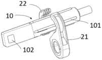
图1是本发明较佳实施例的速度传感器立体示意图;Fig. 1 is a three-dimensional schematic diagram of a speed sensor in a preferred embodiment of the present invention;
图2是本发明较佳实施例的速度传感器的爆炸示意图;Fig. 2 is the explosion schematic diagram of the velocity sensor of preferred embodiment of the present invention;
图3是本发明较佳实施例的第一法兰瓣示意图;Fig. 3 is a schematic diagram of the first flange flap of a preferred embodiment of the present invention;
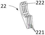
图4是本发明较佳实施例的第二法兰瓣示意图。Fig. 4 is a schematic diagram of the second flange flap of the preferred embodiment of the present invention.
具体实施方式Detailed ways
以下结合附图和较佳实施方式对本发明方案作进一步说明。The scheme of the present invention will be further described below in conjunction with the accompanying drawings and preferred embodiments.
在下面的描述中,阐述了许多具体细节以便使所属技术领域的技术人员更全面地了解本发明。但是,对于所属技术领域内的技术人员明显的是,本发明的实现可不具有这些具体细节中的一些。此外,应当理解的是,本发明并不限于所介绍的特定实施例。相反,可以考虑用下面的特征和要素的任意组合来实施本发明,而无论它们是否涉及不同的实施例。因此,下面的方面、特征、实施例和优点仅作说明之用而不应被看作是权利要求的要素或限定,除非在权利要求中明确提出。此外,本文件中如出现表示方向的词汇,如上下左右、上侧、下侧等,仅是为了表述方便而根据当前附图中部件相对位置进行表述,不应理解为对保护范围的限制。In the following description, numerous specific details are set forth in order to enable those skilled in the art to fully understand the present invention. It will be apparent, however, to one skilled in the art that the present invention may be practiced without some of these specific details. Furthermore, it should be understood that the invention is not limited to the particular embodiments described. Instead, it is conceivable to implement the present invention in any combination of the following features and elements, regardless of whether they relate to different embodiments. Accordingly, the following aspects, features, embodiments and advantages are by way of illustration only and should not be considered elements or limitations of the claims unless explicitly stated in the claims. In addition, if words indicating directions appear in this document, such as up, down, left, right, upper side, lower side, etc., they are only expressed according to the relative positions of the components in the current drawings for the convenience of expression, and should not be construed as limiting the scope of protection.
图1是本发明较佳实施例的速度传感器立体示意图;图2是本发明较佳实施例的速度传感器的爆炸示意图。Fig. 1 is a schematic perspective view of a speed sensor in a preferred embodiment of the present invention; Fig. 2 is a schematic exploded view of a speed sensor in a preferred embodiment of the present invention.
参见图1及图2,在本发明的一个实施例中,提供了一种速度传感器,包括传感器检测部10和法兰20。该传感器检测部10构造为由芯片、插针等通过树脂或塑性材料通过注塑工艺形成的一个独立部件。该法兰20包括第一法兰瓣21和第二法兰瓣22。如图2所示,该第一法兰瓣21和第二法兰瓣22构造为分离的两个独立部件,或在其它实施例中,该第一法兰瓣21和第二法兰瓣22也可构造为部分相连且二者能够相对活动铰接的连体部件。该第一法兰瓣21和第二法兰瓣22组合后形成法兰20,且该第一法兰瓣21和第二法兰瓣22组合后围成一个可容纳传感器检测部10的容纳孔。组装时,该传感器检测部10可在法兰20的容纳孔中轴向移动和周向转动,以调节传感器检测部10的头部感应面102相对该法兰20的轴向距离和周向相位角。Referring to FIG. 1 and FIG. 2 , in one embodiment of the present invention, a speed sensor is provided, including a
图3是本发明较佳实施例的第一法兰瓣示意图;图4是本发明较佳实施例的第二法兰瓣示意图。Fig. 3 is a schematic diagram of the first flange flap of the preferred embodiment of the present invention; Fig. 4 is a schematic diagram of the second flange flap of the preferred embodiment of the present invention.
参见图3和图4,第一法兰瓣21上与传感器检测部10接触的容纳孔表面上设有焊接熔接线211,焊接熔接线211优选为平行间隔的三条。第一法兰瓣21上还设置有可供固定螺栓穿过的安装孔213。第二法兰瓣22上与传感器检测部10接触的容纳孔表面上及与第一法兰瓣21接触的表面上也设有焊接熔接线221,焊接熔接线211优选为平行间隔的三条。上述的焊接熔接线211、221通过熔接焊接工艺尤其是超声波焊接等方式被加热后能变成熔融状态。当传感器检测部10、第一法兰瓣21及第二法兰瓣22三者被组装在一起后,三者之间的焊接熔接线通过熔接焊接方式被加热成熔融状态,使得三个部件两两之间的缝隙被熔融状态的熔接线材料填充,待冷却后,三个部件两两之间牢牢的熔接在一起,最终形成符合要求的速度传感器。Referring to FIG. 3 and FIG. 4 ,
进一步地,如图2所示,传感器检测部10的外壁上设有多个定位凸筋101,该多个定位凸筋101沿着传感器检测部10的延伸的方向延伸。第一法兰瓣21和第二法兰瓣22与传感器检测部10接触的容纳孔内壁上分别设有多个凹槽212、222。这些凹槽212、222能够容纳传感器检测部10上的多个定位凸筋101。多个凹槽212、222的数量不少于多个定位凸筋101的数量,以便于所有的定位凸筋101都能容纳在这些凹槽212、222中。优选地,多个凹槽212、222和多个定位凸筋101的数量相同,且都均匀地分布在周向上。Further, as shown in FIG. 2 , a plurality of
组装时,该传感器检测部10的这些定位凸筋101能够在这些凹槽212、222中滑动,以便调节传感器检测部10的头部感应面102相对法兰20的轴向距离;且这些凹槽212、222能够对定位凸筋101起到周向定位作用,以便将传感器检测部10相对于法兰20保持在周向预定角度。When assembled, the
在本发明的一个实施例中,还提供了一种用于制造上述速度传感器的制造方法。In one embodiment of the present invention, a manufacturing method for manufacturing the above speed sensor is also provided.
该制造方法至少包括以下步骤:The manufacturing method at least includes the following steps:
部件预制造步骤,在该步骤中,分别制造出传感器检测部10、第一法兰瓣21和第二法兰瓣22三个组成部件。其中,可采用模具注塑成型或其它工艺,一次或多次制造出上述三个组成部件。Part pre-manufacturing step, in this step, the three components of the
部件组装步骤,在该步骤中,传感器检测部10、第一法兰瓣21和第二法兰瓣22按要求被组装在一起。其中,组装时,根据客户需求,将传感器检测部10相对于第一法兰瓣21和第二法兰瓣22的轴向距离和周向相位角度调整到预设值。Component assembly step, in this step, the
固接步骤,在该步骤中,将传感器检测部10、第一法兰瓣21及第二法兰瓣22两两之间通过熔接焊接,例如超声波焊接,将三者固接在一起,形成最终速度传感器产品。The affixing step, in this step, the
虽然本发明已以较佳实施例披露如上,但本发明并非限定于此。任何本领域技术人员,在不脱离本发明的精神和范围内所作的各种更动与修改,均应纳入本发明的保护范围内,因此本发明的保护范围应当以权利要求所限定的范围为准。Although the present invention has been disclosed above with preferred embodiments, the present invention is not limited thereto. Any person skilled in the art, without departing from the various changes and modifications made within the spirit and scope of the present invention, all should be included in the protection scope of the present invention, so the protection scope of the present invention should be defined by the claims. allow.
Claims (10)
Priority Applications (2)
| Application Number | Priority Date | Filing Date | Title |
|---|---|---|---|
| CN202111603914.3ACN116338228A (en) | 2021-12-24 | 2021-12-24 | A speed sensor and its manufacturing method |
| EP22215861.0AEP4202446A1 (en) | 2021-12-24 | 2022-12-22 | Speed sensor and manufacturing method therefor |
Applications Claiming Priority (1)
| Application Number | Priority Date | Filing Date | Title |
|---|---|---|---|
| CN202111603914.3ACN116338228A (en) | 2021-12-24 | 2021-12-24 | A speed sensor and its manufacturing method |
Publications (1)
| Publication Number | Publication Date |
|---|---|
| CN116338228Atrue CN116338228A (en) | 2023-06-27 |
Family
ID=84569764
Family Applications (1)
| Application Number | Title | Priority Date | Filing Date |
|---|---|---|---|
| CN202111603914.3APendingCN116338228A (en) | 2021-12-24 | 2021-12-24 | A speed sensor and its manufacturing method |
Country Status (2)
| Country | Link |
|---|---|
| EP (1) | EP4202446A1 (en) |
| CN (1) | CN116338228A (en) |
Citations (5)
| Publication number | Priority date | Publication date | Assignee | Title |
|---|---|---|---|---|
| KR20000008529U (en)* | 1998-10-22 | 2000-05-15 | 밍 루 | Flange fixing device for vehicle wheel speed sensor |
| KR20130068141A (en)* | 2011-12-15 | 2013-06-25 | 대성전기공업 주식회사 | Wheel speed sensor for vehicle |
| CN204341007U (en)* | 2014-12-02 | 2015-05-20 | 北汽福田汽车股份有限公司 | Wheel speed sensors assembly and wheel speed sensors assembly erecting device |
| WO2019025050A1 (en)* | 2017-08-04 | 2019-02-07 | Wabco Gmbh | SPEED SENSOR FOR A VEHICLE, ESPECIALLY A COMMERCIAL VEHICLE, AND A METHOD FOR THE PRODUCTION THEREOF |
| CN211086335U (en)* | 2019-11-13 | 2020-07-24 | 大陆汽车电子(连云港)有限公司 | Wheel speed sensor |
Family Cites Families (5)
| Publication number | Priority date | Publication date | Assignee | Title |
|---|---|---|---|---|
| JP2010008329A (en)* | 2008-06-30 | 2010-01-14 | Bosch Corp | Sensor with mounting mechanism using seal ring and its mounting structure |
| KR102442538B1 (en)* | 2014-01-17 | 2022-09-08 | 알피니티, 엘엘씨 | Fluid monitoring assembly with sensor functionality |
| EP3301342B1 (en)* | 2016-10-03 | 2022-04-13 | Pool Technologie | Instrument-holder for pipe and associated apparatus |
| EP3848255A1 (en)* | 2020-01-08 | 2021-07-14 | Illinois Tool Works Inc. | Sensor housing for a sensor for detecting acceleration and / or tilt angle changes and sensor comprising such a sensor housing |
| KR20230003975A (en)* | 2021-06-30 | 2023-01-06 | 에이치엘만도 주식회사 | Device for sensing wheel speed |
- 2021
- 2021-12-24CNCN202111603914.3Apatent/CN116338228A/enactivePending
- 2022
- 2022-12-22EPEP22215861.0Apatent/EP4202446A1/enactivePending
Patent Citations (5)
| Publication number | Priority date | Publication date | Assignee | Title |
|---|---|---|---|---|
| KR20000008529U (en)* | 1998-10-22 | 2000-05-15 | 밍 루 | Flange fixing device for vehicle wheel speed sensor |
| KR20130068141A (en)* | 2011-12-15 | 2013-06-25 | 대성전기공업 주식회사 | Wheel speed sensor for vehicle |
| CN204341007U (en)* | 2014-12-02 | 2015-05-20 | 北汽福田汽车股份有限公司 | Wheel speed sensors assembly and wheel speed sensors assembly erecting device |
| WO2019025050A1 (en)* | 2017-08-04 | 2019-02-07 | Wabco Gmbh | SPEED SENSOR FOR A VEHICLE, ESPECIALLY A COMMERCIAL VEHICLE, AND A METHOD FOR THE PRODUCTION THEREOF |
| CN211086335U (en)* | 2019-11-13 | 2020-07-24 | 大陆汽车电子(连云港)有限公司 | Wheel speed sensor |
Also Published As
| Publication number | Publication date |
|---|---|
| EP4202446A1 (en) | 2023-06-28 |
Similar Documents
| Publication | Publication Date | Title |
|---|---|---|
| JP3657944B2 (en) | Method for manufacturing resin boot for constant velocity joint Manufacturing apparatus for resin boot for constant velocity joint | |
| JP6171099B2 (en) | Ball joint | |
| JP2015086827A (en) | Turbo fan | |
| CN111923322B (en) | Temperature sensor, injection molding packaging mold and injection molding packaging method | |
| CN109203980B (en) | A new type of internal box support for high-pressure plastic fuel tank | |
| JP2010064671A (en) | Spoiler | |
| CN116338228A (en) | A speed sensor and its manufacturing method | |
| KR101110146B1 (en) | Manufacturing method of constant velocity joint boot and manufacturing apparatus used in the method | |
| KR20170038754A (en) | Wax tree for water meter | |
| CN116212223A (en) | Sensor assembly for blood pump system and method of securing same | |
| US7152656B2 (en) | Manufacturing method for a wax pattern for making a golf club head | |
| JP2013213442A (en) | Impeller and manufacturing method of the same | |
| KR20180104554A (en) | Turbo fan | |
| JP4420279B2 (en) | Plastic Constant Velocity Joint Boot Manufacturing Equipment Plastic Constant Velocity Joint Boot Manufacturing Method Resin Constant Velocity Joint Boot | |
| JP5656904B2 (en) | Manufacturing method of resin thrust washer and mold used for manufacturing the same | |
| JP2015124845A (en) | Pipe-like molded body and its process of manufacture | |
| CN206296424U (en) | A kind of small-sized straight-through casting spherical valve shaping investment pattern device of essence | |
| CN207915901U (en) | A kind of encapsulated grid mold of injection molding | |
| CN112693123A (en) | Integral manufacturing method of sealing product | |
| CN201575914U (en) | Air inlet temperature and pressure sensor | |
| JP2003019732A (en) | Molding method for hollow molded products | |
| JP6607674B2 (en) | Beverage container | |
| CN223039025U (en) | Injection molding insert rubberizing seal structure | |
| CN212004636U (en) | Plastic spinning hydraulic suspension | |
| CN209524064U (en) | A kind of chain wheel assembly |
Legal Events
| Date | Code | Title | Description |
|---|---|---|---|
| PB01 | Publication | ||
| PB01 | Publication | ||
| SE01 | Entry into force of request for substantive examination | ||
| SE01 | Entry into force of request for substantive examination |