CN116335585A - Water control fracturing valve and open hole horizontal well completion string - Google Patents
Water control fracturing valve and open hole horizontal well completion stringDownload PDFInfo
- Publication number
- CN116335585A CN116335585ACN202111609689.4ACN202111609689ACN116335585ACN 116335585 ACN116335585 ACN 116335585ACN 202111609689 ACN202111609689 ACN 202111609689ACN 116335585 ACN116335585 ACN 116335585A
- Authority
- CN
- China
- Prior art keywords
- fracturing
- outer cylinder
- water control
- sliding sleeve
- inner sliding
- Prior art date
- Legal status (The legal status is an assumption and is not a legal conclusion. Google has not performed a legal analysis and makes no representation as to the accuracy of the status listed.)
- Pending
Links
Images


Classifications
- E—FIXED CONSTRUCTIONS
- E21—EARTH OR ROCK DRILLING; MINING
- E21B—EARTH OR ROCK DRILLING; OBTAINING OIL, GAS, WATER, SOLUBLE OR MELTABLE MATERIALS OR A SLURRY OF MINERALS FROM WELLS
- E21B34/00—Valve arrangements for boreholes or wells
- E21B34/06—Valve arrangements for boreholes or wells in wells
- E—FIXED CONSTRUCTIONS
- E21—EARTH OR ROCK DRILLING; MINING
- E21B—EARTH OR ROCK DRILLING; OBTAINING OIL, GAS, WATER, SOLUBLE OR MELTABLE MATERIALS OR A SLURRY OF MINERALS FROM WELLS
- E21B43/00—Methods or apparatus for obtaining oil, gas, water, soluble or meltable materials or a slurry of minerals from wells
- E21B43/25—Methods for stimulating production
- E21B43/26—Methods for stimulating production by forming crevices or fractures
- E21B43/261—Separate steps of (1) cementing, plugging or consolidating and (2) fracturing or attacking the formation
- Y—GENERAL TAGGING OF NEW TECHNOLOGICAL DEVELOPMENTS; GENERAL TAGGING OF CROSS-SECTIONAL TECHNOLOGIES SPANNING OVER SEVERAL SECTIONS OF THE IPC; TECHNICAL SUBJECTS COVERED BY FORMER USPC CROSS-REFERENCE ART COLLECTIONS [XRACs] AND DIGESTS
- Y02—TECHNOLOGIES OR APPLICATIONS FOR MITIGATION OR ADAPTATION AGAINST CLIMATE CHANGE
- Y02E—REDUCTION OF GREENHOUSE GAS [GHG] EMISSIONS, RELATED TO ENERGY GENERATION, TRANSMISSION OR DISTRIBUTION
- Y02E10/00—Energy generation through renewable energy sources
- Y02E10/10—Geothermal energy
Landscapes
- Life Sciences & Earth Sciences (AREA)
- Engineering & Computer Science (AREA)
- Geology (AREA)
- Mining & Mineral Resources (AREA)
- Physics & Mathematics (AREA)
- Environmental & Geological Engineering (AREA)
- Fluid Mechanics (AREA)
- General Life Sciences & Earth Sciences (AREA)
- Geochemistry & Mineralogy (AREA)
- Multiple-Way Valves (AREA)
Abstract
Description
Translated fromChinese技术领域technical field
本发明属于油田勘探钻井机械设备领域,特别涉及一种控水压裂阀和裸眼水平井完井管柱。The invention belongs to the field of oil field exploration and drilling machinery and equipment, and in particular relates to a water control fracturing valve and an open-hole horizontal well completion pipe string.
背景技术Background technique
对于底水油藏,为了延长油藏的开发寿命,国内外的裸眼水平井常常安装ICD\AICD等控水阀进行油井控水。例专利号CN 212296308 U提供的一种采油控水阀就是在智能AICD基础上发展起来的一种新型控水阀。在油藏开发后期,随着采收率的下降,往往需要对油藏进行酸压\加砂压裂改造。ICD\AICD控水阀尽管能够满足控水需要,但由于其水嘴较小,结构复杂,却无法实现大排量对油藏改造的需要。而常规的完井压裂管柱又没有控水的功能,因此,急需研发一种能够同时满足控水采油和压裂改造(酸压和加砂压裂)两种功能的一体化管柱。For bottom-water reservoirs, in order to prolong the development life of the reservoir, open-hole horizontal wells at home and abroad are often installed with ICD\AICD and other water control valves to control oil well water. A kind of oil recovery water control valve provided by example patent number CN 212296308 U is exactly a kind of novel water control valve developed on the basis of intelligent AICD. In the late stage of reservoir development, with the decline of recovery rate, it is often necessary to carry out acid fracturing/sand fracturing stimulation on the reservoir. Although ICD\AICD water control valves can meet the needs of water control, but because of their small nozzles and complex structures, they cannot meet the needs of large displacement for reservoir reconstruction. However, conventional completion fracturing strings do not have the function of water control. Therefore, it is urgent to develop an integrated string that can simultaneously satisfy the two functions of water control oil recovery and fracturing stimulation (acid fracturing and sand fracturing).
发明内容Contents of the invention
针对上述问题,本发明提供了一种控水压裂阀和裸眼水平井完井管柱。In view of the above problems, the present invention provides a water control fracturing valve and an open-hole horizontal well completion string.
本发明的一种控水压裂阀,包括外筒以及设置在所述外筒两端的第一接头和第二接头;A water control fracturing valve of the present invention comprises an outer cylinder and first joints and second joints arranged at both ends of the outer cylinder;
所述外筒在靠近所述第一接头的位置设置有自动流入控制装置;The outer cylinder is provided with an automatic inflow control device at a position close to the first joint;
所述外筒在靠近所述第二接头的位置设置有压裂孔;The outer cylinder is provided with a fracturing hole at a position close to the second joint;
所述外筒内套设有内滑套,所述内滑套沿轴线方向在所述第一接头和所述第二接头之间滑动时实现所述自动流入控制装置和所述压裂孔的交替开启。The inner sleeve of the outer cylinder is provided with an inner sliding sleeve, and when the inner sliding sleeve slides between the first joint and the second joint along the axis direction, the automatic inflow control device and the fracturing hole are connected. Alternately on.
进一步地,所述内滑套与所述外筒之间还设置有限位组件,用于限制所述内滑套在所述外筒内轴向滑动;Further, a limiting component is also provided between the inner sliding sleeve and the outer cylinder for restricting the axial sliding of the inner sliding sleeve in the outer cylinder;
所述限位组件包括设置在所述内滑套外壁的凸起部和设置在所述外筒内壁上的凹槽部;所述凹槽部包括第一凹槽和第二凹槽;The limiting assembly includes a protrusion on the outer wall of the inner sliding sleeve and a groove on the inner wall of the outer cylinder; the groove includes a first groove and a second groove;
所述凸起部与所述第一凹槽配合时,所述内滑套处于第一开关位:所述压裂孔开启并且所述自动流入控制装置关闭;When the protrusion fits with the first groove, the inner sliding sleeve is in the first switch position: the fracturing hole is opened and the automatic inflow control device is closed;
所述凸起部与所述第二凹槽配合时,所述内滑套处于第二开关位:所述压裂孔关闭并且所述自动流入控制装置开启。When the protrusion cooperates with the second groove, the inner sliding sleeve is in the second switch position: the fracturing hole is closed and the automatic inflow control device is opened.
进一步地,所述控水压裂阀还包括密封结构,所述密封结构包括:设置在所述第一接头与所述外筒之间的第一密封圈、设置在所述内滑套与所述外筒之间的第二密封圈和设置在所述第二接头与所述外筒之间的第三密封圈;Further, the water control fracturing valve also includes a sealing structure, and the sealing structure includes: a first sealing ring arranged between the first joint and the outer cylinder, a first sealing ring arranged between the inner sliding sleeve and the outer cylinder, a second sealing ring between the outer cylinder and a third sealing ring arranged between the second joint and the outer cylinder;
和/或,在所述内滑套与所述外筒之间设置的第二密封圈至少有两个,两个所述第二密封圈分别套设在所述内滑套的两端。And/or, there are at least two second sealing rings arranged between the inner sliding sleeve and the outer cylinder, and the two second sealing rings are sleeved on both ends of the inner sliding sleeve respectively.
进一步地,所述内滑套的内壁上设置有用于连接开关工具的连接结构;Further, the inner wall of the inner sliding sleeve is provided with a connecting structure for connecting the switch tool;
和/或,所述内滑套的内壁上开设有第三环状凹槽,用于连接开关工具的弹性爪。And/or, the inner wall of the inner sliding sleeve is provided with a third annular groove for connecting the elastic claw of the switch tool.
进一步地,所述内滑套呈筒状,所述内滑套的外径与所述外筒的内径尺寸匹配;Further, the inner sliding sleeve is cylindrical, and the outer diameter of the inner sliding sleeve matches the inner diameter of the outer cylinder;
所述第一接头和所述第二接头的内径小于所述外筒的内径尺寸。The inner diameters of the first joint and the second joint are smaller than the inner diameter of the outer cylinder.
进一步地,其特征在于,所述自动流入控制装置有多个,沿所述外筒的筒壁周向等间距设置且连通所述外筒的内部和外部;Further, it is characterized in that there are multiple automatic inflow control devices, which are arranged at equal intervals along the circumference of the outer cylinder wall and communicate with the inside and outside of the outer cylinder;
和/或,所述自动流入控制装置为浮板式AICD控水阀,所述控水阀与所述外筒螺纹连接。And/or, the automatic inflow control device is a floating plate AICD water control valve, and the water control valve is screwed to the outer cylinder.
进一步地,所述压裂孔有多个,沿所述外筒的筒壁周向等间距设置且连通所述外筒的内部和外部,所述压裂孔的孔轴线垂直于所述外筒的筒壁。Further, there are a plurality of fracturing holes, which are arranged at equal intervals along the circumference of the outer cylinder wall and communicate with the inside and outside of the outer cylinder, and the axis of the fracturing holes is perpendicular to the outer cylinder the cylinder wall.
本发明还提供了一种裸眼水平井完井管柱,包括本发明的控水压裂阀,所述控水压裂阀设置在井眼下方。The present invention also provides an open hole horizontal well completion string, comprising the water control fracturing valve of the present invention, and the water control fracturing valve is arranged under the wellbore.
进一步地,所述控水压裂阀和所述井眼之间设置有第一封隔器,所述第一封隔器为油胀封隔器或水胀封隔器。Further, a first packer is arranged between the water control fracturing valve and the wellbore, and the first packer is an oil-swellable packer or a water-swellable packer.
进一步地,所述控水压裂阀有多个,多个所述控水压裂阀沿轴线方向依次间隔开布置,多个所述控水压裂阀之间设置有第二封隔器,所述第二封隔器为油胀封隔器或水胀封隔器。Further, there are a plurality of water control fracturing valves, and the plurality of water control fracturing valves are sequentially arranged at intervals along the axis direction, and a second packer is arranged between the plurality of water control fracturing valves, The second packer is an oil-swellable packer or a water-swellable packer.
本发明的一种控水压裂阀的外筒上集成有控水通道和压裂通道,并通过内滑套在外筒内滑动,实现控水通道和压裂通道的交替开启;采用本发明的控水压裂阀所设计的完井管柱,既可以实现小排量的控水采油,延缓油井出水,提高油井寿命;同时又可以选择性实现大排量对油藏的改造。应用于实际过程中,可以满足对裸眼水平井的完井、压裂及后期控水需求。The outer cylinder of the water control fracturing valve of the present invention is integrated with a water control channel and a fracturing channel, and the inner sliding sleeve slides in the outer cylinder to realize the alternate opening of the water control channel and the fracturing channel; The completion string designed by the water-controlled fracturing valve can not only realize the water-controlled oil production with small displacement, delay the water production of the oil well, and improve the life of the oil well; Applied in the actual process, it can meet the needs of completion, fracturing and post-water control of open-hole horizontal wells.
本发明的其它特征和优点将在随后的说明书中阐述,并且,部分地从说明书中变得显而易见,或者通过实施本发明而了解。本发明的目的和其他优点可通过在说明书、权利要求书以及附图中所指出的结构来实现和获得。Additional features and advantages of the invention will be set forth in the description which follows, and in part will be apparent from the description, or may be learned by practice of the invention. The objectives and other advantages of the invention may be realized and attained by the structure pointed out in the written description, claims hereof as well as the appended drawings.
附图说明Description of drawings
为了更清楚地说明本发明实施例或现有技术中的技术方案,下面将对实施例或现有技术描述中所需要使用的附图作一简单地介绍,显而易见地,下面描述中的附图是本发明的一些实施例,对于本领域普通技术人员来讲,在不付出创造性劳动的前提下,还可以根据这些附图获得其他的附图。In order to more clearly illustrate the technical solutions in the embodiments of the present invention or the prior art, the following will briefly introduce the drawings that need to be used in the description of the embodiments or the prior art. Obviously, the accompanying drawings in the following description These are some embodiments of the present invention. Those skilled in the art can also obtain other drawings based on these drawings without creative work.
图1示出了根据本发明实施例的一种控水压裂阀的结构示意图;Fig. 1 shows a schematic structural view of a water control fracturing valve according to an embodiment of the present invention;
图2示出了根据本发明实施例的控水压裂阀与开关工具的连接示意图;Fig. 2 shows a schematic diagram of connection between a water control fracturing valve and a switch tool according to an embodiment of the present invention;
图3示出了根据本发明实施例的一种裸眼水平井完井管柱的结构示意图;Fig. 3 shows a schematic structural view of an open-hole horizontal well completion string according to an embodiment of the present invention;
图4示出了根据本发明实施例的一种带有开关工具的管柱。Fig. 4 shows a pipe string with a switching tool according to an embodiment of the present invention.
图中主要标号说明:Explanation of main symbols in the figure:
1、外筒;2、第一接头;3、第二接头;4、自动流入控制装置;5、压裂孔;6、内滑套;7、凸起部;8、凹槽部;81、第一凹槽;82、第二凹槽;9、第一密封圈;10、第二密封圈;11、第一环状凹槽;12、第二环状凹槽;13、第三密封圈;14、第三环状凹槽;15、开关工具;16、第一环状凸台;17、第二环状凸台;100、控水压裂阀;1. Outer cylinder; 2. First joint; 3. Second joint; 4. Automatic inflow control device; 5. Fracturing hole; 6. Inner sliding sleeve; 7. Raised part; 8. Groove part; 81. The first groove; 82, the second groove; 9, the first sealing ring; 10, the second sealing ring; 11, the first annular groove; 12, the second annular groove; 13, the third sealing ring ; 14, the third annular groove; 15, the switch tool; 16, the first annular boss; 17, the second annular boss; 100, the water control fracturing valve;
21、表层套管;22、技术套管;23、对接油管;24、尾管悬挂器;25、井眼;26、第一封隔器;27、第二封隔器;28、浮鞋;200、完井管柱;21. Surface casing; 22. Technical casing; 23. Docking tubing; 24. Liner hanger; 25. Wellbore; 26. First packer; 27. Second packer; 28. Floating shoe; 200. Completion string;
31、连续油管;32、第三封隔器;33、定压滑套;34、机械定位器;35、圆头引头。31. Coiled tubing; 32. The third packer; 33. Constant pressure sliding sleeve; 34. Mechanical positioner; 35. Round head.
具体实施方式Detailed ways
为使本发明实施例的目的、技术方案和优点更加清楚,下面将结合本发明实施例中的附图,对本发明实施例中的技术方案进行清楚、完整地说明,显然,所描述的实施例是本发明一部分实施例,而不是全部的实施例。基于本发明中的实施例,本领域普通技术人员在没有做出创造性劳动前提下所获得的所有其他实施例,都属于本发明保护的范围。In order to make the purpose, technical solutions and advantages of the embodiments of the present invention more clear, the technical solutions in the embodiments of the present invention will be clearly and completely described below in conjunction with the accompanying drawings in the embodiments of the present invention. Obviously, the described embodiments It is a part of embodiments of the present invention, but not all embodiments. Based on the embodiments of the present invention, all other embodiments obtained by persons of ordinary skill in the art without making creative efforts belong to the protection scope of the present invention.
考虑到现有技术中,在底水油藏的开发后期,随着采收率的降低,需要对由此进行压裂改造,常规的控水阀尽管能够满足控水要求,但是很难实现大排量对油藏改造的需要,在常规的完井压裂管柱不具有控水能力的前提下,本发明提出了一种控水压裂阀和裸眼水平井完井管柱,该控水压裂阀集控水压裂功能于一体,直接应用于完井管柱中,实现完井管柱兼具控水压裂功能,下面通过实施例进行描述。Considering that in the existing technology, in the later stage of development of bottom water reservoirs, with the decrease of recovery rate, it is necessary to carry out fracturing reconstruction. Although conventional water control valves can meet the water control requirements, it is difficult to achieve large Displacement requires reservoir stimulation. On the premise that conventional well completion fracturing strings do not have water control capability, the present invention proposes a water control fracturing valve and open hole horizontal well completion string. The water control The fracturing valve integrates the functions of water control and fracturing, and is directly applied to the completion string to realize the function of the completion string as well as the function of water control and fracturing. The following examples are used to describe it.
实施例一:Embodiment one:
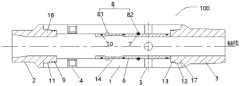
为便于对本实施例进行理解,首先对本申请实施例所公开的一种控水压裂阀进行详细介绍。如图1所示,为本发明实施例的一种控水压裂阀100的结构示意图,包括外筒1以及设置在外筒1两端的第一接头2和第二接头3;In order to facilitate the understanding of this embodiment, a water control fracturing valve disclosed in the embodiment of the present application is firstly introduced in detail. As shown in FIG. 1 , it is a schematic structural diagram of a water
外筒1在靠近第一接头2的位置设置有自动流入控制装置4;The outer cylinder 1 is provided with an automatic
外筒1在靠近第二接头3的位置设置有压裂孔5;The outer cylinder 1 is provided with a
外筒1内套设有内滑套6,内滑套6沿轴线方向在第一接头2和第二接头3之间滑动时实现自动流入控制装置4和压裂孔5的交替开启。The inner sliding
其中压裂孔5用于作为层段压裂液向地层的注入通道(压裂通道);自动流入控制装置4用于作为控水通道实现控水增油的作用。Among them, the fracturing
在本申请的实施例中,内滑套6与外筒1之间还设置有限位组件,用于限制内滑套6在外筒1内轴向滑动;In the embodiment of the present application, a limiting component is also provided between the inner sliding
限位组件包括设置在内滑套6外壁的凸起部7和设置在外筒1内壁上的凹槽部8;凹槽部8包括第一凹槽81和第二凹槽82;The limit assembly includes a raised
凸起部7与第一凹槽81配合时,内滑套6处于第一开关位:压裂孔5开启并且自动流入控制装置4关闭;When the
凸起部7与第二凹槽82配合时,内滑套6处于第二开关位:压裂孔5关闭并且自动流入控制装置4开启。When the
参见图1,本申请的实施例中,第一凹槽81和第二凹槽82位于压裂孔5和自动流入控制装置4之间,当内滑套6向自动流入控制装置4方向滑动,直至凸起部7卡入第一凹槽81内时,内滑套6限定在第一开关位,此时压裂孔5处于打开状态,自动流入控制装置4被内滑套6关闭。当内滑套6向压裂孔5方向滑动,直至凸起部7卡入第二凹槽82内时,内滑套6限定在第二开关位,此时压裂孔5被内滑套6堵住,压裂孔5关闭,自动流入控制装置4处于开启状态;图1中所示的内滑套6正处于第二开关位。应当理解的是,凸起部7和凹槽部8配合实现内滑套6限位功能即可,凸起部7的形状可以不作特别要求。Referring to FIG. 1 , in the embodiment of the present application, the
可选地,控水压裂阀100还包括密封结构,密封结构包括:Optionally, the water
设置在第一接头2与外筒1之间的第一密封圈9;用于避免第一接头2和外筒1之间出现泄漏,实现第一接头2位置处密封,如图1所示,在本申请的实施例中,第一接头2在与外筒1连接的位置设置有第一环状凸台16,外筒1在连接第一接头2的第一端部设置有与第一环状凸台16尺寸匹配的第一环状凹槽11,可选的,第一环状凸台16可以是螺纹连接第一环状凹槽11;在第一环状凸台16和第一环状凹槽11之间设置有两个第一密封圈9,第一密封圈9通过卡槽连接的方式固定在第一环状凸台16的外壁上。第一密封圈9为弹性件,在受力的情况下形变从而封堵第一环状凸台16和第一环状凹槽11之间的间隙,从而实现第一接头2和外筒1之间的密封。The
设置在内滑套6与外筒1之间的第二密封圈10;在本申请的实施例中,在内滑套6与外筒1之间设置的第二密封圈10有三个,其中两个第二密封圈10分别套设在内滑套6的两端,还有一个第二密封圈10设置在内滑套6的中间部位,在内滑套6处于第一开关位时,第二密封圈10用于实现对自动流入控制装置4进行密封,在内滑套6处于第二开关位时,第二密封圈10用于实现对压裂孔5进行密封。The
设置在第二接头3与外筒1之间的第三密封圈13;用于避免第二接头3和外筒1之间出现泄漏,实现第二接头3位置处密封,如图1所示,在本申请的实施例中,第二接头3在与外筒1连接的位置设置有第二环状凸台17,外筒1在连接第二接头3的第二端部设置有与第二环状凸台17尺寸匹配的第二环状凹槽12,可选的,第二环状凸台17可以是螺纹连接第二环状凹槽12;第二环状凸台17和第二环状凹槽12之间设置有两个第三密封圈13,第三密封圈13通过卡槽连接的方式固定在第二环状凸台17的外壁上。第三密封圈13为弹性件,在受力的情况下形变从而封堵第二环状凸台17和第二环状凹槽12之间的间隙,从而实现二接头和外筒1之间的密封。The
第二密封圈10和第三密封圈13同样为弹性件,通过在受力的情况下形变从而实现封堵功能。The
具体的,内滑套6的内壁上设置有用于连接开关工具15的连接结构;用于与开关工具15固定连接,从而实现在开关工具15的操作下,内滑套6在外筒1内进行轴向滑动。在本申请的实施例中,连接结构为第三环状凹槽14,第三环状凹槽14开设在内滑套6的内壁上,用于连接开关工具15的弹性爪。Specifically, the inner wall of the inner sliding
如图2所示,为本申请的控水压裂阀100与开关工具15的连接示意图,包含有开关工具15的管柱伸入到控水压裂阀100的内部后,开关工具15在第三环状凹槽14的位置时,弹性爪张开后伸入第三环状凹槽14内并抵紧第三环状凹槽14内壁,当操作开关工具15沿轴向运动时可以带动内滑套6沿轴向运动;图2中显示的是内滑套6在开关工具15的操作带动下处于第一开关位。As shown in Figure 2, it is a schematic diagram of the connection between the water
在本申请的实施例中,内滑套6呈筒状,内滑套6的外径与外筒1的内径尺寸匹配;第一接头2和第二接头3的内径小于外筒1的内径尺寸。如图1和图2中所示,本实施例中,第一接头2和第二接头3在外筒1连接的位置处,内径与内滑套6的内径相同;因为内滑套6自身具有一定的厚度,第一接头2和第二接头3的这种尺寸设计能够避免内滑套6从外筒1中滑出。In the embodiment of the present application, the inner sliding
在本申请的实施例中,自动流入控制装置4有多个,多个自动流入控制装置4沿外筒1的筒壁周向等间距设置;应当理解的是,自动流入控制装置4的设置个数和设置方案,本领域技术人员可以根据实际的水平井油藏情况等现实状况进行选择。In the embodiment of the present application, there are multiple automatic
可选的,自动流入控制装置4为浮板式AICD(Autonomous Inflow ControlDevice,自动流入控制设备)控水阀,浮板式AICD控水阀与外筒1螺纹连接。Optionally, the automatic
在本申请的实施例中,压裂孔5有多个,沿外筒1的筒壁周向等间距设置,压裂孔5的孔轴线垂直于外筒1的筒壁。应当理解的是,压裂孔5的设置个数和设置方案,本领域技术人员可以根据实际的水平井油藏情况等现实状况进行选择,例如可以根据需要设置多排压裂孔5以进一步增大压裂孔5的总面积。In the embodiment of the present application, there are a plurality of fracturing
本实施例中,参见图1,在控水压裂阀100上设置了两个浮板式AICD控水阀和四个压裂孔5。In this embodiment, referring to FIG. 1 , two floating plate AICD water control valves and four fracturing
实施例二:Embodiment two:
基于相同的技术构思,本申请实施例还提供一种裸眼水平井完井管柱,如图3所示,为根据本发明实施例的一种裸眼水平井完井管柱200的结构示意图,包括表层套管21、技术套管22、对接油管23和尾管悬挂器24,表层套管21套设在技术套管22外,技术套管22沿轴线方向依次连接对接油管23、尾管悬挂器24和井眼25。图3中,技术套管22和对接油管23用单一的竖线作为示意。Based on the same technical concept, the embodiment of the present application also provides an open-hole horizontal well completion string, as shown in FIG. 3 , which is a structural schematic diagram of an open-hole horizontal
还包括本发明控水压裂阀100,控水压裂阀100设置在井眼25下方。在完井管柱200的末端设置有浮鞋28。It also includes the water
控水压裂阀100的第一接头2朝向井眼25的方向分布,控水压裂阀100和井眼25之间设置有第一封隔器26,第一封隔器26为油胀封隔器或水胀封隔器。The
可选的,控水压裂阀100有多个,多个控水压裂阀100沿轴线方向依次间隔开布置,多个控水压裂阀100之间设置有第二封隔器27,第二封隔器27为油胀封隔器或水胀封隔器。Optionally, there are multiple water-controlled
本实施例中的油胀\水胀封隔器对井眼适应性强,封隔器遇油\水膨胀自动坐封,无须打压坐封,坐封安全可靠,有效解决封隔器的砂卡问题。The oil-swelling/water-swelling packer in this example has strong adaptability to the wellbore, and the packer will automatically set and seal when encountering oil/water expansion, without pressure setting, and the setting is safe and reliable, effectively solving the sand jam of the packer question.
应当理解的是,控水压裂阀100的数量选择,本领域技术人员可以根据实际情况确定。参见图3,在本申请的实施例中,控水压裂阀100有四个,沿着水平井的管柱轴线方向依次排布。通过“控水压裂阀+油胀\水胀封隔器”组成完井管柱200的主体部分,应用在实际中,可以通过开关工具实现选择性分层控水和压裂,既可以实现小排量的控水采油,延缓油井出水,提高油井寿命;同时又可以选择性实现大排量对油藏的改造,实现了控水采油与油藏改造两个功能一体化设计,大大提高采油效率。且该完井管柱结构简单,下入安全,能够降低作业费用和施工风险,提高油井寿命。It should be understood that the selection of the number of water-controlled
基于本发明实施例二的裸眼水平井完井管柱的完井工艺流程为:The completion process flow of the open-hole horizontal well completion string based on
首先,钻完井过程中,将表层套管和技术套管水泥固井;First, during the drilling and completion process, cement the surface casing and technical casing;
然后,将钻井管柱(钻杆)与控水压裂一体化管柱(即本发明实施例二中完井管柱的主体部分)连接在一起,并该管柱送入水平裸眼井段内,将控水压裂一体化管柱上部的尾管悬挂器悬挂于上部技术套管内;Then, the drilling string (drill pipe) and the integrated string for water control and fracturing (that is, the main part of the completion string in
最后,井口连接泵送管线,正循环将套管环空钻井泥浆替净,然后投球憋压,丢手尾管挂。将上部的钻杆由尾管挂密封处脱扣取出。Finally, the wellhead is connected to the pumping pipeline, and the drilling mud in the casing annulus is replaced by positive circulation, and then the ball is thrown to suppress the pressure, and the liner is dropped. Take out the upper drill pipe from the seal of the liner hanger.
基于本发明实施例二的裸眼水平井完井管柱的压裂工艺流程如下所示(以完井后就进行油藏压裂为例进行说明):The fracturing process flow of the open-hole horizontal well completion string based on
(1)完井:如果选择完井后压裂,控水压裂阀下井时,其控水压裂阀的内滑套设置为第一开关位,即通过AICD控水阀进入地层通道处于关闭状态。(1) Completion: If fracturing after well completion is selected, when the water control fracturing valve goes into the well, the inner sliding sleeve of the water control fracturing valve is set to the first switch position, that is, the channel entering the formation through the AICD water control valve is closed state.
(2)压裂:完井完成后,参见图3,下入对接油管与尾管悬挂器对接,然后下入带有开关工具的管柱。找到首层控水压裂阀(靠近井眼处的第一个控水压裂阀)。井口泵压,坐封封隔器,并打开定压滑套,泵入压裂液实现对该段的压裂。其它层的控水压裂阀可以采用同种方案进行压裂操作。(2) Fracturing: After the completion of the well, see Figure 3, run the butt tubing to connect with the liner hanger, and then run the string with the switch tool. Locate the first water control frac valve (the first water control frac valve near the wellbore). Pump pressure at the wellhead, set the packer, open the constant pressure sliding sleeve, and pump fracturing fluid to realize fracturing of the section. The water-controlled fracturing valves of other layers can use the same scheme for fracturing operations.
(3)控水增油:紧接上面步骤(2),压裂完成后下放带有开关工具的管柱到完井管柱中,从最末梢依次上提带有开关工具的管柱,使各个控水压裂阀中的内滑套到第二开关位,关闭压裂通道(压裂孔5),同时打开控水通道(AICD控水阀),从而完成各层控水压裂阀的控水通道的打开。(3) Controlling water and increasing oil production: Immediately after the above step (2), after the fracturing is completed, lower the string with the switch tool into the completion string, and lift the string with the switch tool sequentially from the extreme end, so that The inner sliding sleeve in each water control fracturing valve is at the second switch position, the fracturing channel (fracturing hole 5) is closed, and the water control channel (AICD water control valve) is opened at the same time, thereby completing the water control fracturing valve of each layer. Control the opening of the water channel.
根据本发明的另一个较佳实施例,如果管柱初期完井时,下井控水压裂阀处于控水采油状态(即压裂通道关闭,内滑套处于第一开关位),采油后期需要对油层进行酸压或加砂压裂时,也可以下入带有开关工具的连续油管,实现对各段的储层改造。图4示出了根据本发明实施例的一种带有开关工具的管柱,如图4中所示,带开关工具的管柱的主体部分包括依次连接的连续油管31、第三封隔器32、定压滑套33、开关工具15、机械定位器34和圆头引头35。According to another preferred embodiment of the present invention, if when the pipe string is initially completed, the water-controlled fracturing valve in the well is in the state of water-controlled oil production (that is, the fracturing channel is closed, and the inner sliding sleeve is in the first switch position), and the oil recovery later stage needs to When acid fracturing or sand fracturing is performed on the oil layer, the coiled tubing with switch tools can also be lowered to realize the transformation of each section of the reservoir. Fig. 4 shows a pipe string with a switch tool according to an embodiment of the present invention. As shown in Fig. 4, the main part of the pipe string with a switch tool includes coiled
尽管参照前述实施例对本发明进行了详细的说明,本领域的普通技术人员应当理解:其依然可以对前述各实施例所记载的技术方案进行修改,或者对其中部分技术特征进行等同替换;而这些修改或者替换,并不使相应技术方案的本质脱离本发明各实施例技术方案的精神和范围。Although the present invention has been described in detail with reference to the aforementioned embodiments, those skilled in the art should understand that: they can still modify the technical solutions described in the aforementioned embodiments, or perform equivalent replacements for some of the technical features; and these The modification or replacement does not make the essence of the corresponding technical solutions deviate from the spirit and scope of the technical solutions of the various embodiments of the present invention.
Claims (10)
Priority Applications (1)
| Application Number | Priority Date | Filing Date | Title |
|---|---|---|---|
| CN202111609689.4ACN116335585A (en) | 2021-12-24 | 2021-12-24 | Water control fracturing valve and open hole horizontal well completion string |
Applications Claiming Priority (1)
| Application Number | Priority Date | Filing Date | Title |
|---|---|---|---|
| CN202111609689.4ACN116335585A (en) | 2021-12-24 | 2021-12-24 | Water control fracturing valve and open hole horizontal well completion string |
Publications (1)
| Publication Number | Publication Date |
|---|---|
| CN116335585Atrue CN116335585A (en) | 2023-06-27 |
Family
ID=86879565
Family Applications (1)
| Application Number | Title | Priority Date | Filing Date |
|---|---|---|---|
| CN202111609689.4APendingCN116335585A (en) | 2021-12-24 | 2021-12-24 | Water control fracturing valve and open hole horizontal well completion string |
Country Status (1)
| Country | Link |
|---|---|
| CN (1) | CN116335585A (en) |
Citations (4)
| Publication number | Priority date | Publication date | Assignee | Title |
|---|---|---|---|---|
| CN103422846A (en)* | 2013-07-19 | 2013-12-04 | 中国石油天然气股份有限公司 | Open hole horizontal well completion fracturing integrated pipe column |
| CN108397181A (en)* | 2018-04-08 | 2018-08-14 | 中国石油化工股份有限公司 | A kind of pressure break and the Joint Implementation tubing string and method of the aquatic production of control |
| CN113622887A (en)* | 2020-05-06 | 2021-11-09 | 中国石油化工股份有限公司 | Fracturing and intelligent water control integrated device |
| CN113622868A (en)* | 2020-05-06 | 2021-11-09 | 中国石油化工股份有限公司 | Differential pressure type sliding sleeve with water control function |
- 2021
- 2021-12-24CNCN202111609689.4Apatent/CN116335585A/enactivePending
Patent Citations (4)
| Publication number | Priority date | Publication date | Assignee | Title |
|---|---|---|---|---|
| CN103422846A (en)* | 2013-07-19 | 2013-12-04 | 中国石油天然气股份有限公司 | Open hole horizontal well completion fracturing integrated pipe column |
| CN108397181A (en)* | 2018-04-08 | 2018-08-14 | 中国石油化工股份有限公司 | A kind of pressure break and the Joint Implementation tubing string and method of the aquatic production of control |
| CN113622887A (en)* | 2020-05-06 | 2021-11-09 | 中国石油化工股份有限公司 | Fracturing and intelligent water control integrated device |
| CN113622868A (en)* | 2020-05-06 | 2021-11-09 | 中国石油化工股份有限公司 | Differential pressure type sliding sleeve with water control function |
Similar Documents
| Publication | Publication Date | Title |
|---|---|---|
| US11473391B2 (en) | Packer sealing element with non-swelling layer | |
| CN113494273A (en) | Well completion pipe string and production pipe string of electric pump oil production well and construction method of well completion pipe string and production pipe string | |
| CN109763795B (en) | Bypass diversion screen pipe | |
| CN212201962U (en) | Ball type hydraulic multiple switch bypass valve | |
| CN210068069U (en) | Anti-leakage double-sealing well-flushing packer | |
| CN113863888B (en) | Underground three-channel integrated blowout preventer for double-tube drilling | |
| CN116265692A (en) | Half-way well cementation floating shoe device, tubular column and half-way well cementation operation method | |
| CN113445962B (en) | Hydraulic double-layer pipe double-gradient downhole blowout prevention valve | |
| CN108798609B (en) | Sand control screen with self-locking switch | |
| CN106481326A (en) | The no chock pressure difference fracturing strings of self controllable supercharging | |
| CN108691523A (en) | A kind of concentric little oil pipe gas-lift working barrel and its airlift unit | |
| CN219220366U (en) | A ball-free casing annulus communication device for downhole operation | |
| CN116335585A (en) | Water control fracturing valve and open hole horizontal well completion string | |
| CN110017127B (en) | Acid fracturing water control integrated device, acid fracturing water control pipe column and acid fracturing water control method | |
| WO2025000912A1 (en) | Hydraulic lifting multi-gradient drilling string, drilling system, and drilling method | |
| CN115653555A (en) | A resettable layered and segmented pressure drive water injection process string and method | |
| CN206530322U (en) | Down-hole casing twin-stage bores expansion gear | |
| CN114482922B (en) | Annular space safety control device for multitube production tubular column and method for using annular space safety control device | |
| CN115992652A (en) | Open hole horizontal well cement packing sectional water control sand prevention completion string and method | |
| CN114439422A (en) | Sliding sleeve with sand prevention structure | |
| CN114856495A (en) | Underground device for testing gas-water output profile of coal bed gas combined production well | |
| US4192378A (en) | Port valve isolation packer | |
| RU2713819C1 (en) | Bottom-hole fluid flow switch in well for various operating modes (embodiments) | |
| CN114458155A (en) | Wellhead fixed type radial drilling well completion method | |
| CN220415315U (en) | Wellbore pressure control device |
Legal Events
| Date | Code | Title | Description |
|---|---|---|---|
| PB01 | Publication | ||
| PB01 | Publication | ||
| SE01 | Entry into force of request for substantive examination | ||
| SE01 | Entry into force of request for substantive examination |