CN116330267A - A control method based on singular point calculation of industrial robot wrist - Google Patents
A control method based on singular point calculation of industrial robot wristDownload PDFInfo
- Publication number
- CN116330267A CN116330267ACN202111590845.7ACN202111590845ACN116330267ACN 116330267 ACN116330267 ACN 116330267ACN 202111590845 ACN202111590845 ACN 202111590845ACN 116330267 ACN116330267 ACN 116330267A
- Authority
- CN
- China
- Prior art keywords
- robot
- joint
- matrix
- velocity
- jacobian matrix
- Prior art date
- Legal status (The legal status is an assumption and is not a legal conclusion. Google has not performed a legal analysis and makes no representation as to the accuracy of the status listed.)
- Pending
Links
Images

Classifications
- B—PERFORMING OPERATIONS; TRANSPORTING
- B25—HAND TOOLS; PORTABLE POWER-DRIVEN TOOLS; MANIPULATORS
- B25J—MANIPULATORS; CHAMBERS PROVIDED WITH MANIPULATION DEVICES
- B25J9/00—Programme-controlled manipulators
- B25J9/16—Programme controls
- B25J9/1602—Programme controls characterised by the control system, structure, architecture
- B25J9/1607—Calculation of inertia, jacobian matrixes and inverses
- Y—GENERAL TAGGING OF NEW TECHNOLOGICAL DEVELOPMENTS; GENERAL TAGGING OF CROSS-SECTIONAL TECHNOLOGIES SPANNING OVER SEVERAL SECTIONS OF THE IPC; TECHNICAL SUBJECTS COVERED BY FORMER USPC CROSS-REFERENCE ART COLLECTIONS [XRACs] AND DIGESTS
- Y02—TECHNOLOGIES OR APPLICATIONS FOR MITIGATION OR ADAPTATION AGAINST CLIMATE CHANGE
- Y02P—CLIMATE CHANGE MITIGATION TECHNOLOGIES IN THE PRODUCTION OR PROCESSING OF GOODS
- Y02P90/00—Enabling technologies with a potential contribution to greenhouse gas [GHG] emissions mitigation
- Y02P90/02—Total factory control, e.g. smart factories, flexible manufacturing systems [FMS] or integrated manufacturing systems [IMS]
Landscapes
- Engineering & Computer Science (AREA)
- Physics & Mathematics (AREA)
- Mathematical Physics (AREA)
- Automation & Control Theory (AREA)
- Robotics (AREA)
- Mechanical Engineering (AREA)
- Numerical Control (AREA)
- Manipulator (AREA)
Abstract
Description
Translated fromChinese技术领域technical field
本发明属于工业机器人控制领域,具体的,为一种基于工业机器人腕部奇异点计算的控制方法。The invention belongs to the field of industrial robot control, in particular, it is a control method based on the singular point calculation of the industrial robot wrist.
背景技术Background technique
工业机器人可以对多个运动轴,包括方向、位置和工作流程进行编程。工业机器人通常包括具有多个轴的机器人臂以及可编程控制器(控制装置),控制器在运行中控制或调整工业机器人的运动过程。Industrial robots can program multiple axes of motion, including orientation, position, and workflow. An industrial robot usually includes a robot arm with multiple axes and a programmable controller (control device), which controls or adjusts the motion process of the industrial robot during operation.
运动学奇异是机械结构不可避免的固有特性。其不仅限制了机器人真正运行空间,当机器人运动到奇异点时,其雅可比矩阵不存在逆解,从而使关节跟踪速度和加速度无穷大,形成冲击进而将造成工业机器人稳定性变差,跟踪能力下降等问题,这些不足严重影响机器人的运动性能。Kinematic singularity is an unavoidable inherent property of mechanical structures. It not only limits the real running space of the robot, but when the robot moves to a singular point, its Jacobian matrix does not have an inverse solution, so that the joint tracking speed and acceleration are infinite, forming an impact, which will cause the stability of the industrial robot to deteriorate and the tracking ability to decline These problems seriously affect the motion performance of the robot.
针对机器人运动学奇异位形问题,提出一种计算六轴机器人腕部奇异位形的方法。通过计算出机器人处于奇异位形时各关节的状态,使机器人远离奇异位形,提高工业机器人性能。Aiming at the singularity problem of robot kinematics, a method for calculating the singularity of the wrist of a six-axis robot is proposed. By calculating the state of each joint when the robot is in a singular configuration, the robot is kept away from the singular configuration and the performance of the industrial robot is improved.
发明内容Contents of the invention
本发明提供了一种基于计算工业机器人奇异位形的控制方法,可以克服机器人在奇异位形时稳定性差的缺陷。The invention provides a control method based on calculating the singular configuration of an industrial robot, which can overcome the defect of poor stability of the robot in the singular configuration.
为实现上述目的,本发明采用如下技术方案,To achieve the above object, the present invention adopts the following technical solutions,
一种基于工业机器人腕部奇异点计算的控制方法,包括以下步骤:A control method based on the singular point calculation of the wrist of an industrial robot, comprising the following steps:
步骤一:定义基坐标系和机器人机械臂关节坐标系,且保证机器人关节坐标系与基坐标系方向相同,根据机器人运动参数,建立机器人运动学模型;Step 1: Define the base coordinate system and the robot arm joint coordinate system, and ensure that the robot joint coordinate system is in the same direction as the base coordinate system, and establish a robot kinematics model according to the robot motion parameters;
步骤二:根据机器人机械臂运动学模型的连杆变换,求取机器人运动学正解;Step 2: According to the connecting rod transformation of the robot arm kinematics model, obtain the positive solution of the robot kinematics;
步骤三:求解机器人机械臂的速度雅可比矩阵,得到包括机器人关节平动速度和转动速度的速度雅可比矩阵;Step 3: Solve the velocity Jacobian matrix of the robot arm to obtain the velocity Jacobian matrix including the translational velocity and rotational velocity of the robot joints;
步骤四:对求取的速度雅可比矩阵进行解耦运算,将该矩阵按照平动速度和转动速度分为多个矩阵;Step 4: Decoupling the obtained velocity Jacobian matrix, and dividing the matrix into multiple matrices according to the translational velocity and rotational velocity;
步骤五:根据解耦后的速度雅可比矩阵,计算整个雅可比矩阵的行列式结果,在行列式结果为零时,则为机器人机械臂的奇异点;Step 5: Calculate the determinant result of the entire Jacobian matrix according to the decoupled velocity Jacobian matrix. When the determinant result is zero, it is the singular point of the robot arm;
步骤六:在得到机器人机械臂的奇异点后,根据绕开奇异点的轨迹对机器人机械臂的控制。Step 6: After obtaining the singular point of the robot arm, control the robot arm according to the trajectory that bypasses the singular point.
所述对机器人进行运动学模型的连杆变换,其变换矩阵为:The connecting rod transformation of the kinematics model is carried out to the robot, and its transformation matrix is:


并计算机器人运动学正解,计算公式和结果为:And calculate the positive solution of robot kinematics, the calculation formula and result are:

其中:in:
nx=-s5(s1s4+c4(c1c2s3+c1c3s2))-c5(c1s2s3-c1c2c3)nx =-s5 (s1 s4 +c4 (c1 c2 s3 +c1 c3 s2 ))-c5 (c1 s2 s3 -c1 c2 c3 )
ny=s5(c1s4-c4(c2s1s3+c3s1s2))-c5(s1s2s3-c2c3s1)ny =s5 (c1 s4 -c4 (c2 s1 s3 +c3 s1 s2 ))-c5 (s1 s2 s3 -c2 c3 s1 )
nz=-s23c5-c23c4s5nz =-s23 c5 -c23 c4 s5
ox=s6(c5(s1s4+c4(c1c2s3+c1c3s2))-s5(c1s2s3-c1c2c3))-c6(c4s1-s4(c1c2s3+c1c3s2))ox =s6 (c5 (s1 s4 +c4 (c1 c2 s3 +c1 c3 s2 ))-s5 (c1 s2 s3 -c1 c2 c3 ) )-c6 (c4 s1 -s4 (c1 c2 s3 +c1 c3 s2 ))
oy=c6(c1c4+s4(c2s1s3+c3s1s2))-s6(c5(c1s4-c4(c2s1s3+c3s1s2))+s5(s1s2s3-c2c3s1))oy =c6 (c1 c4 +s4 (c2 s1 s3 +c3 s1 s2 ))-s6 (c5 (c1 s4 -c4 (c2 s1 s3 +c3 s1 s2 ))+s5 (s1 s2 s3 -c2 c3 s1 ))
oz=c23c6s4-s6(s23s5-c23c4c5)oz =c23 c6 s4 -s6 (s23 s5 -c23 c4 c5 )
ax=s6(c4s1-s4(c1c2s3+c1c3s2))+c6(c5(s1s4+c4(c1c2s3+c1c3s2))-s5(c1s2s3-c1c2c3))ax =s6 (c4 s1 -s4 (c1 c2 s3 +c1 c3 s2 ))+c6 (c5 (s1 s4 +c4 (c1 c2 s3 +c1 c3 s2 ))-s5 (c1 s2 s3 -c1 c2 c3 ))
ay=-s6(c1c4+s4(c2s1s3+c3s1s2))-c6(c5(c1s4-c4(c2s1s3+c3s1s2))+s5(s1s2s3-c2c3s1))ay =-s6 (c1 c4 +s4 (c2 s1 s3 +c3 s1 s2 ))-c6 (c5 (c1 s4 -c4 (c2 s1 s3 +c3 s1 s2 ))+s5 (s1 s2 s3 -c2 c3 s1 ))
az=-c6(s23s5-c23c4c5)-c23s4s6az =-c6 (s23 s5 -c23 c4 c5 )-c23 s4 s6
Px=c1(L1+L4c23+L3s23+L2s2)Px =c1 (L1 +L4 c23 +L3 s23 +L2 s2 )
Py=s1(L1+L4c23+L3s23+L2s2)Py =s1 (L1 +L4 c23 +L3 s23 +L2 s2 )
Pz=L3c23-L4s23+L2c2Pz =L3 c23 -L4 s23 +L2 c2
其中,c1-c6,s1-s6依次表示机器人各关节变量θ1-θ6的正弦值和余弦值,c23,s23分别表示关节变量θ2和θ3之和的正弦值和余弦值;L1表示机器人关节1和关节2之间连杆在水平方向上的长度,L2表示机器人关节2和关节3之间连杆长度,L3表示机器人关节3和关节4之间连杆在垂直方向上的长度,L4表示机器人关节3和关节4之间连杆在水平方向上的长度;nx-nz,ox-oz,ax-az表示组成旋转矩阵的三个单位向量,每个参数都是旋转矩阵的一部分;Px,Py,Pz表示机器人6轴原点坐标在机器人基坐标系下的表示。Among them, c1 -c6 , s1 -s6 represent the sine value and cosine value of each joint variable θ1 -θ6 of the robot in turn, c23 , s23 represent the sine value of the sum of joint variables θ2 and θ3 respectively and cosine value; L1 represents the length of the connecting rod between joint 1 and
所述求解机器人的速度雅可比矩阵,包括如下步骤:The speed Jacobian matrix of the solution robot comprises the following steps:
步骤一:确定机械臂体速度、机械臂的速度雅可比矩阵关系,得到方程:Step 1: Determine the relationship between the body speed of the manipulator and the Jacobian matrix of the speed of the manipulator, and obtain the equation:

其中ξ为机械臂体速度,J为机械臂的速度雅可比矩阵,q为关节位置变量,

其中0vn代表末端执行器的线速度,0ωn代表末端执行器的角速度,Jv为雅可比矩阵的上半部分,定义关节速度向量

步骤二:确定机械臂末端执行器的线速度,采用微分链式法则处理,计算方程为:Step 2: Determine the linear velocity of the end effector of the manipulator, and use the differential chain rule to process it. The calculation equation is:

其中

由此确定矩阵Jv的第i列结果为:Therefore, the i-th column of the matrix Jv is determined to be:

计算方程为:The calculation equation is:

其中

步骤三:确定机器人机械臂速度雅可比矩阵中的转动关节角速度矩阵,可得到矩阵第i列的角速度,为:Step 3: Determine the rotational joint angular velocity matrix in the robot arm velocity Jacobian matrix, and the angular velocity of the i-th column of the matrix can be obtained as:

其中Jωi代表速度雅可比矩阵第i列的角速度向量矩阵,其中
所述对机器人机械臂的速度雅可比矩阵做解耦处理,处理方式为按平动关节的平动速度和转动关节的转动速度分解速度雅可比矩阵,得到:The decoupling process is performed on the velocity Jacobian matrix of the robot arm, and the processing method is to decompose the velocity Jacobian matrix according to the translational velocity of the translational joint and the rotational velocity of the rotational joint, and obtain:

其中JO为转动关节速度列向量矩阵,JP为平动关节的速度列向量矩阵,J11和J22代表分块矩阵中的中间矩阵,定义JO为:Among them, JO is the velocity column vector matrix of the rotational joint, JP is the velocity column vector matrix of the translational joint, J11 and J22 represent the intermediate matrix in the block matrix, and JO is defined as:

由于关节4-6交于同一点o,因此可选择坐标系,使得o4=o5=o6=o7=o,其中o4、o5、o6和o7代表关节坐标系原点,则转动关节速度列向量矩阵可表示为:Since the joints 4-6 intersect at the same point o, the coordinate system can be selected such that o4 =o5 =o6 =o7 =o, where o4 , o5 , o6 and o7 represent the origin of the joint coordinate system, Then the rotational joint velocity column vector matrix can be expressed as:

其中

所述对机器人机械臂的速度雅可比矩阵做解耦处理,由于手腕轴线交于同一点o,因此解耦得到的矩阵J12为零矩阵,即:The decoupling process is performed on the speed Jacobian matrix of the robotic arm of the robot. Since the wrist axis intersects at the same point o, the matrixJ12 obtained by decoupling is a zero matrix, namely:

所述计算整个雅可比矩阵的行列式结果,即:The result of calculating the determinant of the entire Jacobian matrix is:
detJ=detJ11detJ22,detJ = detJ11 detJ22 ,
其中对于detJ11、detJ22中的一个为0,或者两者都为0时,矩阵J11和J22中对应的机器人机械臂关节平动速度和/或转动速度为奇异点。When one of detJ11 and detJ22 is 0, or both of them are 0, the corresponding translation velocity and/or rotation velocity of the joints of the robotic arm in the matrices J11 and J22 are singular points.
若矩阵J11和J22的行列式为0,则矩阵中的列向量线性相关。If the determinants of the matrices J11 and J22 are 0, the column vectors in the matrices are linearly related.
本发明具有以下有益效果和优点:The present invention has following beneficial effect and advantage:
1.可以解决工业机器人在运动中遇到腕部奇异点不能通过的问题,通过计算出机器人处于奇异位形时各关节的状态,使机器人远离奇异位形,提高工业机器人性能。1. It can solve the problem that the industrial robot cannot pass through the singular point of the wrist during the movement. By calculating the state of each joint when the robot is in the singular configuration, the robot can be kept away from the singular configuration and the performance of the industrial robot can be improved.
2.针对机器人运动学奇异位形问题,提出一种根据机器人正向运动学结合速度雅可比矩阵计算六轴机器人腕部奇异位形的方法。通过计算出机器人处于奇异位形时各关节的状态,使机器人远离奇异位形,提高工业机器人性能。2. Aiming at the singularity problem of robot kinematics, a method for calculating the singularity of the wrist of a six-axis robot is proposed based on the forward kinematics of the robot combined with the velocity Jacobian matrix. By calculating the state of each joint when the robot is in a singular configuration, the robot is kept away from the singular configuration and the performance of the industrial robot is improved.
附图说明Description of drawings
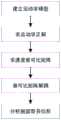
图1工业机器人奇异位形计算流程图;Fig. 1 Flowchart of singular configuration calculation of industrial robot;
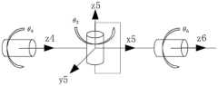
图2工业机器人运动学建模示意图;Fig. 2 Schematic diagram of industrial robot kinematics modeling;
图3工业机器腕部奇异位形示意图。Figure 3 Schematic diagram of the singular configuration of the wrist of an industrial machine.
具体实施方式Detailed ways
为了使本发明的目的、技术方案及优点更加清楚明白,以下结合附图及实施例,对本发明进行进一步详细说明。应当理解,此处所描述的具体实施例仅仅用以解释本发明,并不用于限定本发明。In order to make the object, technical solution and advantages of the present invention clearer, the present invention will be further described in detail below in conjunction with the accompanying drawings and embodiments. It should be understood that the specific embodiments described here are only used to explain the present invention, not to limit the present invention.
如图1所示,本发明包括如下步骤:As shown in Figure 1, the present invention comprises the following steps:
1.建立工业机器人的运动学模型1. Establish the kinematics model of the industrial robot
2.求解工业机器人运动学正解2. Solve the positive solution of industrial robot kinematics
3.求解工业机器人的速度雅可比矩阵3. Solve the speed Jacobian matrix of industrial robots
4.对雅可比矩阵进行解耦运算4. Decoupling the Jacobian matrix
5.求解工业机器人腕部奇异位形5. Solve the singular configuration of the wrist of an industrial robot
建立工业机器人的运动学模型,根据6轴工业机器人关节和连杆结构,建立机器人运动学模型。Establish the kinematics model of the industrial robot, and establish the kinematics model of the robot according to the joint and connecting rod structure of the 6-axis industrial robot.
所述机器人关节和连杆结构,关节坐标系定义如图2所示:The robot joint and connecting rod structure, the definition of the joint coordinate system is shown in Figure 2:
图中{1}、{2}、{3}、{4}、{5}、{6}代表各个关节处的坐标系,其坐标系方向均定义为与基坐标系相同。坐标系{i}(i=1,2,3)的原点定义为机器人i轴轴心和i+1轴轴心公垂线与机器人i轴轴心的交点,腕关节坐标系{4}、{5}、{6}原点定义为机器人四轴轴心和五轴轴心交点。{1}, {2}, {3}, {4}, {5}, and {6} in the figure represent the coordinate systems at each joint, and the directions of the coordinate systems are defined to be the same as the base coordinate system. The origin of the coordinate system {i} (i=1, 2, 3) is defined as the intersection point of the common vertical line of the robot’s i-axis axis and the i+1 axis axis and the robot’s i-axis axis. The wrist joint coordinate system {4}, The origin of {5} and {6} is defined as the intersection point of the four-axis axis and the five-axis axis of the robot.
所述机器人运动学模型的连杆变换矩阵如下:The link transformation matrix of the robot kinematics model is as follows:


计算机器人运动学正解Computational Robot Kinematics Positive Solution

其中in
nx=-s5(s1s4+c4(c1c2s3+c1c3s2))-c5(c1s2s3-c1c2c3)nx =-s5 (s1 s4 +c4 (c1 c2 s3 +c1 c3 s2 ))-c5 (c1 s2 s3 -c1 c2 c3 )
ny=s5(c1s4-c4(c2s1s3+c3s1s2))-c5(s1s2s3-c2c3s1)ny =s5 (c1 s4 -c4 (c2 s1 s3 +c3 s1 s2 ))-c5 (s1 s2 s3 -c2 c3 s1 )
nz=-s23c5-c23c4s5nz =-s23 c5 -c23 c4 s5
ox=s6(c5(s1s4+c4(c1c2s3+c1c3s2))-s5(c1s2s3-c1c2c3))-c6(c4s1-s4(c1c2s3+c1c3s2))ox =s6 (c5 (s1 s4 +c4 (c1 c2 s3 +c1 c3 s2 ))-s5 (c1 s2 s3 -c1 c2 c3 ) )-c6 (c4 s1 -s4 (c1 c2 s3 +c1 c3 s2 ))
oy=c6(c1c4+s4(c2s1s3+c3s1s2))-s6(c5(c1s4-c4(c2s1s3+c3s1s2))+s5(s1s2s3-c2c3s1))oy =c6 (c1 c4 +s4 (c2 s1 s3 +c3 s1 s2 ))-s6 (c5 (c1 s4 -c4 (c2 s1 s3 +c3 s1 s2 ))+s5 (s1 s2 s3 -c2 c3 s1 ))
oz=c23c6s4-s6(s23s5-c23c4c5)oz =c23 c6 s4 -s6 (s23 s5 -c23 c4 c5 )
ax=s6(c4s1-s4(c1c2s3+c1c3s2))+c6(c5(s1s4+c4(c1c2s3+c1c3s2))-s5(c1s2s3-c1c2c3))ax =s6 (c4 s1 -s4 (c1 c2 s3 +c1 c3 s2 ))+c6 (c5 (s1 s4 +c4 (c1 c2 s3 +c1 c3 s2 ))-s5 (c1 s2 s3 -c1 c2 c3 ))
ay=-s6(c1c4+s4(c2s1s3+c3s1s2))-c6(c5(c1s4-c4(c2s1s3+c3s1s2))+s5(s1s2s3-c2c3s1))ay =-s6 (c1 c4 +s4 (c2 s1 s3 +c3 s1 s2 ))-c6 (c5 (c1 s4 -c4 (c2 s1 s3 +c3 s1 s2 ))+s5 (s1 s2 s3 -c2 c3 s1 ))
az=-c6(s23s5-c23c4c5)-c23s4s6az =-c6 (s23 s5 -c23 c4 c5 )-c23 s4 s6
Px=c1(L1+L4c23+L3s23+L2s2)Px =c1 (L1 +L4 c23 +L3 s23 +L2 s2 )
Py=s1(L1+L4c23+L3s23+L2s2)Py =s1 (L1 +L4 c23 +L3 s23 +L2 s2 )
Pz=L3c23-L4s23+L2c2Pz =L3 c23 -L4 s23 +L2 c2
求解工业机器人的速度雅可比矩阵,雅可比矩阵是关节速度空间,到笛卡尔速度空间的映射,其逆矩阵,就是笛卡尔速度空间,到关节速度空间的映射。雅可比矩阵是时变的线性映射。Solve the velocity Jacobian matrix of industrial robots. The Jacobian matrix is the mapping from the joint velocity space to the Cartesian velocity space, and its inverse matrix is the mapping from the Cartesian velocity space to the joint velocity space. The Jacobian matrix is a time-varying linear map.

其中,ξ和J由下式给出where ξ and J are given by

向量ξ被称为体速度,注意这个速度向量并非位置变量的倒数,这是由于角速度向量不是任何时变数量的倒数,矩阵J被称为机械臂的雅可比矩阵。J是一个6×n的矩阵,其中n是机器人中的连杆数量。The vector ξ is called the body velocity. Note that this velocity vector is not the reciprocal of the position variable. This is because the angular velocity vector is not the reciprocal of any time-varying quantity. The matrix J is called the Jacobian matrix of the manipulator. J is a 6×n matrix, where n is the number of links in the robot.
想要描述刚体的运动,需要6个变量,其中3个平移速度分量,3个旋转速度分量,想要确定这6个输出变量,至少需要6个输出,且雅可比矩阵的6个列向量必须线性无关,也就是说这个6个列向量可以张成一个6维的向量空间。To describe the motion of a rigid body, 6 variables are required, including 3 translational velocity components and 3 rotational velocity components. To determine these 6 output variables, at least 6 outputs are required, and the 6 column vectors of the Jacobian matrix must be Linearly independent, that is to say, the 6 column vectors can be stretched into a 6-dimensional vector space.
末端执行器的线速度是

因此,矩阵Jv的第i列(记为Jvi)可由下式给出:Therefore, the ith column of matrix Jv (denoted Jvi ) can be given by:

其中,矩阵的第i列Jvi为Among them, the i-th column Jvi of the matrix is

雅可比矩阵的下半部分为The lower half of the Jacobian matrix is
Jω=(Jω1…Jωn)Jω =(Jω1 …Jωn )
其中,矩阵的第i列Jωi为Among them, the i-th column Jωi of the matrix is

当雅可比矩阵的行列式等于零,该方阵是奇异矩阵,此情况下雅可比矩阵的逆矩阵不存在,不能通过笛卡尔速度求出对应的关节速度,通过求解雅可比矩阵行列式为零的情况,可以确定机器人的奇异位形。When the determinant of the Jacobian matrix is equal to zero, the square matrix is a singular matrix. In this case, the inverse matrix of the Jacobian matrix does not exist, and the corresponding joint speed cannot be obtained through the Cartesian velocity. By solving the Jacobian matrix, the determinant is zero. situation, the singular configuration of the robot can be determined.
一般情况下,难以求解非线性方程detJ(q)=0,但是对于装备有球形手腕的机械臂,可以对雅可比矩阵进行解耦,求解奇异点位置。In general, it is difficult to solve the nonlinear equation detJ(q)=0, but for a robotic arm equipped with a spherical wrist, the Jacobian matrix can be decoupled to solve for the singular point position.
通过解耦,可以分离出腕部奇异点的雅可比矩阵。By decoupling, the Jacobian of the wrist singularity can be isolated.
对于有球形手腕的6轴机器人,雅可比矩阵为6*6矩阵,当For a 6-axis robot with a spherical wrist, the Jacobian matrix is a 6*6 matrix, when
detJ(q)=0detJ(q)=0
时,位形q为奇异点When , the configuration q is a singular point
若将雅可比矩阵分解成如下3*3的矩阵块If the Jacobian matrix is decomposed into the following 3*3 matrix blocks

最后三个关节总为转动关节The last three joints are always rotational joints

由于手腕轴线交于同一点o,若我们选择坐标系使得o4=o5=o6=o7=o,则Since the wrist axis intersects at the same point o, if we choose the coordinate system such that o4 =o5 =o6 =o7 =o, then

因此,雅可比矩阵有以下形式Therefore, the Jacobian matrix has the form

其行列式为Its determinant is
detJ=detJ11detJ22detJ = detJ11 detJ22
手腕奇异点wrist singularity

因为

其中


根据运动学正解,可以计算According to the positive solution of kinematics, it can be calculated


其中


J22是一个3*3的方阵,当向量

Claims (7)


Priority Applications (1)
| Application Number | Priority Date | Filing Date | Title |
|---|---|---|---|
| CN202111590845.7ACN116330267A (en) | 2021-12-23 | 2021-12-23 | A control method based on singular point calculation of industrial robot wrist |
Applications Claiming Priority (1)
| Application Number | Priority Date | Filing Date | Title |
|---|---|---|---|
| CN202111590845.7ACN116330267A (en) | 2021-12-23 | 2021-12-23 | A control method based on singular point calculation of industrial robot wrist |
Publications (1)
| Publication Number | Publication Date |
|---|---|
| CN116330267Atrue CN116330267A (en) | 2023-06-27 |
Family
ID=86890083
Family Applications (1)
| Application Number | Title | Priority Date | Filing Date |
|---|---|---|---|
| CN202111590845.7APendingCN116330267A (en) | 2021-12-23 | 2021-12-23 | A control method based on singular point calculation of industrial robot wrist |
Country Status (1)
| Country | Link |
|---|---|
| CN (1) | CN116330267A (en) |
Cited By (3)
| Publication number | Priority date | Publication date | Assignee | Title |
|---|---|---|---|---|
| CN116551731A (en)* | 2023-02-21 | 2023-08-08 | 山东新一代信息产业技术研究院有限公司 | Method based on optimal motion performance of mechanical arm |
| CN117798938A (en)* | 2024-03-01 | 2024-04-02 | 北京长木谷医疗科技股份有限公司 | Non-singular evaluation control method and device for multi-joint robot |
| CN117817654A (en)* | 2023-11-23 | 2024-04-05 | 佛山科学技术学院 | A motion planning method for heavy-load robots |
Citations (3)
| Publication number | Priority date | Publication date | Assignee | Title |
|---|---|---|---|---|
| US5159249A (en)* | 1989-05-16 | 1992-10-27 | Dalila Megherbi | Method and apparatus for controlling robot motion at and near singularities and for robot mechanical design |
| CN110802600A (en)* | 2019-11-28 | 2020-02-18 | 合肥工业大学 | A Singularity Handling Method for 6-DOF Articulated Robot |
| CN112743575A (en)* | 2020-12-29 | 2021-05-04 | 北京理工大学 | Series industrial robot static rigidity identification system and method for processing site |
- 2021
- 2021-12-23CNCN202111590845.7Apatent/CN116330267A/enactivePending
Patent Citations (3)
| Publication number | Priority date | Publication date | Assignee | Title |
|---|---|---|---|---|
| US5159249A (en)* | 1989-05-16 | 1992-10-27 | Dalila Megherbi | Method and apparatus for controlling robot motion at and near singularities and for robot mechanical design |
| CN110802600A (en)* | 2019-11-28 | 2020-02-18 | 合肥工业大学 | A Singularity Handling Method for 6-DOF Articulated Robot |
| CN112743575A (en)* | 2020-12-29 | 2021-05-04 | 北京理工大学 | Series industrial robot static rigidity identification system and method for processing site |
Non-Patent Citations (1)
| Title |
|---|
| 周辉: "六轴机器人奇异点规避与轨迹规划研究", 中国优秀硕士论文全文库信息科技辑, 15 September 2019 (2019-09-15), pages 10 - 24* |
Cited By (4)
| Publication number | Priority date | Publication date | Assignee | Title |
|---|---|---|---|---|
| CN116551731A (en)* | 2023-02-21 | 2023-08-08 | 山东新一代信息产业技术研究院有限公司 | Method based on optimal motion performance of mechanical arm |
| CN117817654A (en)* | 2023-11-23 | 2024-04-05 | 佛山科学技术学院 | A motion planning method for heavy-load robots |
| CN117798938A (en)* | 2024-03-01 | 2024-04-02 | 北京长木谷医疗科技股份有限公司 | Non-singular evaluation control method and device for multi-joint robot |
| CN117798938B (en)* | 2024-03-01 | 2024-05-28 | 北京长木谷医疗科技股份有限公司 | A non-singular evaluation control method and device for a multi-joint robot |
Similar Documents
| Publication | Publication Date | Title |
|---|---|---|
| CN109895101B (en) | A method for obtaining unique numerical solution of inverse kinematics of articulated manipulator | |
| CN116330267A (en) | A control method based on singular point calculation of industrial robot wrist | |
| CN108673509B (en) | Motion control method of six-degree-of-freedom wrist offset type serial mechanical arm | |
| CN107589934B (en) | Solving method for inverse kinematics analytic solution of joint type mechanical arm | |
| CN110757454B (en) | Path planning method and device for cooperative rotation of double robots | |
| CN103692433B (en) | Model decoupling three-arm-lever five-freedom-degree translation welding robot and decoupling method thereof | |
| CN102785248B (en) | Motion control method of decoupling type 6-DOF (six degrees of freedom) industrial robot | |
| CN114378827B (en) | Dynamic target tracking and grabbing method based on overall control of mobile mechanical arm | |
| CN108621162A (en) | A kind of manipulator motion planning method | |
| CN105382835A (en) | Robot path planning method for passing through wrist singular point | |
| CN113127989A (en) | Six-degree-of-freedom mechanical arm inverse kinematics analysis solution control method | |
| CN106041932B (en) | A kind of motion control method of UR robots | |
| CN106844951A (en) | The method and system of super redundant robot's inverse kinematics are solved based on segmentation geometric method | |
| Long et al. | Robotic arm simulation by using matlab and robotics toolbox for industry application | |
| CN107791248A (en) | Control method based on the six degree of freedom serial manipulator for being unsatisfactory for pipper criterions | |
| CN111791234A (en) | Anti-collision control algorithm for working positions of multiple robots in narrow space | |
| CN117817654A (en) | A motion planning method for heavy-load robots | |
| CN111993414A (en) | Mechanical arm multi-joint linkage control method | |
| CN108972548B (en) | A Mobile Platform-Robot System Modeling Method | |
| Ge | Kinematics modeling of redundant manipulator based on screw theory and Newton-Raphson method | |
| CN110576438A (en) | Simplified kinematics solution method, device and system for linked flexible manipulator | |
| CN109693235B (en) | A human eye-like visual tracking device and its control method | |
| Guo | Multi-degree-of-freedom robot arm motion simulation based on MATLAB | |
| Zhang et al. | Modeling and workspace analysis of collaborative advanced fiber placement machine | |
| KR20150063308A (en) | Mobile manipulator system and optimizatiom method thereof |
Legal Events
| Date | Code | Title | Description |
|---|---|---|---|
| PB01 | Publication | ||
| PB01 | Publication | ||
| SE01 | Entry into force of request for substantive examination | ||
| SE01 | Entry into force of request for substantive examination |