CN116327455A - A fusion device holding instrument - Google Patents
A fusion device holding instrumentDownload PDFInfo
- Publication number
- CN116327455A CN116327455ACN202111599693.7ACN202111599693ACN116327455ACN 116327455 ACN116327455 ACN 116327455ACN 202111599693 ACN202111599693 ACN 202111599693ACN 116327455 ACN116327455 ACN 116327455A
- Authority
- CN
- China
- Prior art keywords
- clamping
- transmission
- flexible
- assembly
- flexible part
- Prior art date
- Legal status (The legal status is an assumption and is not a legal conclusion. Google has not performed a legal analysis and makes no representation as to the accuracy of the status listed.)
- Granted
Links
Images


Classifications
- A—HUMAN NECESSITIES
- A61—MEDICAL OR VETERINARY SCIENCE; HYGIENE
- A61F—FILTERS IMPLANTABLE INTO BLOOD VESSELS; PROSTHESES; DEVICES PROVIDING PATENCY TO, OR PREVENTING COLLAPSING OF, TUBULAR STRUCTURES OF THE BODY, e.g. STENTS; ORTHOPAEDIC, NURSING OR CONTRACEPTIVE DEVICES; FOMENTATION; TREATMENT OR PROTECTION OF EYES OR EARS; BANDAGES, DRESSINGS OR ABSORBENT PADS; FIRST-AID KITS
- A61F2/00—Filters implantable into blood vessels; Prostheses, i.e. artificial substitutes or replacements for parts of the body; Appliances for connecting them with the body; Devices providing patency to, or preventing collapsing of, tubular structures of the body, e.g. stents
- A61F2/02—Prostheses implantable into the body
- A61F2/30—Joints
- A61F2/46—Special tools for implanting artificial joints
- A61F2/4603—Special tools for implanting artificial joints for insertion or extraction of endoprosthetic joints or of accessories thereof
- A61F2/4611—Special tools for implanting artificial joints for insertion or extraction of endoprosthetic joints or of accessories thereof of spinal prostheses
- A—HUMAN NECESSITIES
- A61—MEDICAL OR VETERINARY SCIENCE; HYGIENE
- A61F—FILTERS IMPLANTABLE INTO BLOOD VESSELS; PROSTHESES; DEVICES PROVIDING PATENCY TO, OR PREVENTING COLLAPSING OF, TUBULAR STRUCTURES OF THE BODY, e.g. STENTS; ORTHOPAEDIC, NURSING OR CONTRACEPTIVE DEVICES; FOMENTATION; TREATMENT OR PROTECTION OF EYES OR EARS; BANDAGES, DRESSINGS OR ABSORBENT PADS; FIRST-AID KITS
- A61F2/00—Filters implantable into blood vessels; Prostheses, i.e. artificial substitutes or replacements for parts of the body; Appliances for connecting them with the body; Devices providing patency to, or preventing collapsing of, tubular structures of the body, e.g. stents
- A61F2/02—Prostheses implantable into the body
- A61F2/30—Joints
- A61F2/44—Joints for the spine, e.g. vertebrae, spinal discs
- A61F2/4455—Joints for the spine, e.g. vertebrae, spinal discs for the fusion of spinal bodies, e.g. intervertebral fusion of adjacent spinal bodies, e.g. fusion cages
- A—HUMAN NECESSITIES
- A61—MEDICAL OR VETERINARY SCIENCE; HYGIENE
- A61F—FILTERS IMPLANTABLE INTO BLOOD VESSELS; PROSTHESES; DEVICES PROVIDING PATENCY TO, OR PREVENTING COLLAPSING OF, TUBULAR STRUCTURES OF THE BODY, e.g. STENTS; ORTHOPAEDIC, NURSING OR CONTRACEPTIVE DEVICES; FOMENTATION; TREATMENT OR PROTECTION OF EYES OR EARS; BANDAGES, DRESSINGS OR ABSORBENT PADS; FIRST-AID KITS
- A61F2/00—Filters implantable into blood vessels; Prostheses, i.e. artificial substitutes or replacements for parts of the body; Appliances for connecting them with the body; Devices providing patency to, or preventing collapsing of, tubular structures of the body, e.g. stents
- A61F2/02—Prostheses implantable into the body
- A61F2/30—Joints
- A61F2/46—Special tools for implanting artificial joints
- A61F2/4603—Special tools for implanting artificial joints for insertion or extraction of endoprosthetic joints or of accessories thereof
- A61F2002/4625—Special tools for implanting artificial joints for insertion or extraction of endoprosthetic joints or of accessories thereof with relative movement between parts of the instrument during use
- A61F2002/4627—Special tools for implanting artificial joints for insertion or extraction of endoprosthetic joints or of accessories thereof with relative movement between parts of the instrument during use with linear motion along or rotating motion about the instrument axis or the implantation direction, e.g. telescopic, along a guiding rod, screwing inside the instrument
- A—HUMAN NECESSITIES
- A61—MEDICAL OR VETERINARY SCIENCE; HYGIENE
- A61F—FILTERS IMPLANTABLE INTO BLOOD VESSELS; PROSTHESES; DEVICES PROVIDING PATENCY TO, OR PREVENTING COLLAPSING OF, TUBULAR STRUCTURES OF THE BODY, e.g. STENTS; ORTHOPAEDIC, NURSING OR CONTRACEPTIVE DEVICES; FOMENTATION; TREATMENT OR PROTECTION OF EYES OR EARS; BANDAGES, DRESSINGS OR ABSORBENT PADS; FIRST-AID KITS
- A61F2/00—Filters implantable into blood vessels; Prostheses, i.e. artificial substitutes or replacements for parts of the body; Appliances for connecting them with the body; Devices providing patency to, or preventing collapsing of, tubular structures of the body, e.g. stents
- A61F2/02—Prostheses implantable into the body
- A61F2/30—Joints
- A61F2/46—Special tools for implanting artificial joints
- A61F2002/4631—Special tools for implanting artificial joints the prosthesis being specially adapted for being cemented
Landscapes
- Health & Medical Sciences (AREA)
- Engineering & Computer Science (AREA)
- Biomedical Technology (AREA)
- Orthopedic Medicine & Surgery (AREA)
- Transplantation (AREA)
- Neurology (AREA)
- Heart & Thoracic Surgery (AREA)
- Oral & Maxillofacial Surgery (AREA)
- Cardiology (AREA)
- Vascular Medicine (AREA)
- Life Sciences & Earth Sciences (AREA)
- Animal Behavior & Ethology (AREA)
- General Health & Medical Sciences (AREA)
- Public Health (AREA)
- Veterinary Medicine (AREA)
- Physical Education & Sports Medicine (AREA)
- Surgical Instruments (AREA)
- Lining Or Joining Of Plastics Or The Like (AREA)
Abstract
Translated fromChinese
Description
Translated fromChinese技术领域technical field
本申请涉及医疗器械领域,特别是涉及一种融合器把持器械。The present application relates to the field of medical devices, in particular to a fusion device holding device.
背景技术Background technique
TLIF(Transforaminal Lumbar Interbody Fusion)是指经椎间孔入路腰椎体间融合术。由于是从患者背部椎管更侧面的中线切口进入,这一术式大大降低了手术中的肌肉剥离数量,而且TLIF可以提供前柱的支撑和稳定,重建相应节段的正常解剖曲度,从而维持或恢复腰椎整体的生理曲度。TLIF (Transforaminal Lumbar Interbody Fusion) refers to transforaminal lumbar interbody fusion. Since it is entered from the midline incision on the side of the spinal canal on the back of the patient, this surgical method greatly reduces the amount of muscle stripping during the operation, and TLIF can provide support and stability of the anterior column and reconstruct the normal anatomical curvature of the corresponding segment, thereby Maintain or restore the overall physiological curvature of the lumbar spine.
而目前用于TLIF手术的融合器及其把持器不能使融合器实现植入角度可调,导致最终的支撑位置不贴合终板,稳定性差。有的医生术中通过往复摆动把持器,或敲击融合器末端,以便使融合器到达理想的植入位置。把持器的往复摆动或敲击融合器末端易对神经根及硬膜囊造成伤害,而且使得TLIF手术变得更加复杂。另外,由于锥体终板为凹面,两终板中心间隙大,外缘间隙小,对于高度大于宽度的融合器,以宽度方向通过终板外缘的间隙,更易植入融合器,然而融合器置入椎间后需要旋转90°放正,此时可能造成融合器相对融合器把持器械的转动,造成把持松动,滑丝。However, the fusion device and its holder currently used in TLIF surgery cannot allow the fusion device to achieve an adjustable implantation angle, resulting in that the final support position does not fit the endplate and the stability is poor. Some doctors swing the handle back and forth during the operation, or tap the end of the fusion device so that the fusion device can reach the ideal implantation position. The back-and-forth swing of the gripper or knocking on the end of the fusion device can easily cause damage to the nerve root and dural sac, and make the TLIF operation more complicated. In addition, because the endplates of the cone are concave, the center gap between the two endplates is large and the gap between the outer edges is small. For a cage whose height is greater than its width, it is easier to insert the cage through the gap between the outer edges of the endplates in the width direction. After being inserted into the intervertebral space, it needs to be rotated 90° to put it right. At this time, the fusion cage may rotate relative to the fusion cage holding device, resulting in loosening of the grip and slipping of the wire.
有鉴于此,如何提供一种针对在经椎间孔入路腰椎体间融合术中,实现融合器植入角度可调,且把持稳定的把持器械,即为本发明待解决的技术问题。In view of this, how to provide a holding instrument with adjustable implantation angle and stable holding for transforaminal lumbar interbody fusion is the technical problem to be solved in the present invention.
发明内容Contents of the invention
鉴于以上所述现有技术的缺点,本申请的目的在于提供一种融合器把持器械及植入器械组件,用于解决现有手术中的问题。In view of the above-mentioned shortcomings of the prior art, the purpose of the present application is to provide a fusion device holding instrument and implantation instrument assembly, which is used to solve the problems in the existing operation.
为实现上述目的及其他相关目的,本申请一方面提供一种融合器把持器械,包括邻接的芯轴和第一驱动组件;所述第一驱动组件可驱动芯轴沿其轴向方向转动;所述芯轴包括第一柔性部;还包括依次邻接的夹持组件、第二柔性部和内杆;所述内杆套设于所述芯轴;还包括依次邻接的夹持头、第三柔性部、外杆和第二驱动组件;所述夹持组件设于夹持头内;所述外杆套设于所述内杆;所述第二驱动组件可驱动外杆相对于内杆的延伸方向往复运动,以使所述夹持组件突出或缩进所述夹持头,所述夹持组件被设置为适于在突出夹持头的状态下张开,在缩进夹持头的状态下合拢;所述第一柔性部、第二柔性部和第三柔性部相配合;还包括用于驱动第三柔性部并带动第一柔性部和第二柔性部弯曲的第三驱动组件。In order to achieve the above purpose and other related purposes, the present application provides, on the one hand, a cage holding instrument, comprising an adjacent mandrel and a first drive assembly; the first drive assembly can drive the mandrel to rotate along its axial direction; the The mandrel includes a first flexible part; it also includes a sequentially adjacent clamping assembly, a second flexible part and an inner rod; the inner rod is sheathed on the mandrel; it also includes sequentially adjacent clamping heads, a third flexible part, an outer rod and a second driving assembly; the clamping assembly is set in the clamping head; the outer rod is sleeved on the inner rod; the second driving assembly can drive the extension of the outer rod relative to the inner rod Direction reciprocating movement, so that the clamping assembly protrudes or retracts the clamping head, and the clamping assembly is set to be suitable for opening under the state of protruding the clamping head, and retracting the state of the clamping head The bottom is closed; the first flexible part, the second flexible part and the third flexible part cooperate; and a third driving assembly for driving the third flexible part and driving the first flexible part and the second flexible part to bend.
在本发明的一些实施方式中,所述芯轴远离第一驱动组件的一端设有第一螺纹段。In some embodiments of the present invention, the end of the mandrel away from the first driving assembly is provided with a first thread segment.
在本发明的一些实施方式中,所述夹持组件包括两个相对设置的夹持臂;各所述夹持臂分别包括邻接的过渡臂和抓臂,各所述过渡臂分别与所述第二柔性部连接。In some embodiments of the present invention, the clamping assembly includes two opposite clamping arms; each of the clamping arms includes an adjacent transition arm and a gripping arm, and each of the transition arms is respectively connected to the first The two flexible parts are connected.
在本发明的一些实施方式中,还包括与内杆连接的手持部;所述手持部上设有芯轴通过孔。In some embodiments of the present invention, it also includes a handle part connected to the inner rod; the handle part is provided with a mandrel passing hole.
在本发明的一些实施方式中,所述第二驱动组件包括套设于内杆的第二驱动部,所述第二驱动部与所述外杆连接。In some embodiments of the present invention, the second driving assembly includes a second driving part sheathed on the inner rod, and the second driving part is connected to the outer rod.
在本发明的一些实施方式中,所述内杆上设有第二螺纹段;所述第二驱动部上设有与第二螺纹段相配合的第一螺纹孔。In some embodiments of the present invention, the inner rod is provided with a second threaded segment; the second driving part is provided with a first threaded hole matched with the second threaded segment.
在本发明的一些实施方式中,所述第二驱动部的内径小于所述外杆的外径。In some embodiments of the present invention, the inner diameter of the second driving part is smaller than the outer diameter of the outer rod.
在本发明的一些实施方式中,所述外杆的内径与内杆的外径相配合;所述内杆的内径与芯轴的外径相配合。In some embodiments of the present invention, the inner diameter of the outer rod matches the outer diameter of the inner rod; the inner diameter of the inner rod matches the outer diameter of the mandrel.
在本发明的一些实施方式中,还包括沿外杆轴向对称分布的第一传动部和第二传动部,所述第三柔性部和第三驱动组件经第一传动部和第二传动部连接。In some embodiments of the present invention, it further includes a first transmission part and a second transmission part symmetrically distributed along the axis of the outer rod, and the third flexible part and the third drive assembly pass through the first transmission part and the second transmission part. connect.
在本发明的一些实施方式中,所述第三驱动组件包括圆盘和与圆盘中心铰接的第三驱动部,所述圆盘上分别设有相对圆盘中心中心对称的第一滑槽和第二滑槽,所述第三驱动部上设有可沿第一滑槽滑动的第一滑块以及可沿第二滑槽滑动的第二滑块;所述第一滑块与所述第一传动部连接;所述第二滑块与所述第二传动部连接。In some embodiments of the present invention, the third drive assembly includes a disc and a third drive part hinged to the center of the disc, and the disc is respectively provided with a first chute and a first chute symmetrical to the center of the disc. The second chute, the third driving part is provided with a first slider that can slide along the first chute and a second slider that can slide along the second chute; the first slider and the second chute A transmission part is connected; the second slider is connected with the second transmission part.
在本发明的一些实施方式中,所述第一滑块上设有第一卡接孔,所述第一卡接孔内设有第一传动固位件,所述第一传动部与第一传动固位件连接、且通过第一卡接孔卡接;所述圆盘上还设有第三滑槽;所述第一传动部可随第一传动固位件沿第三滑槽滑动。In some embodiments of the present invention, the first sliding block is provided with a first clamping hole, and a first transmission retainer is provided in the first clamping hole, and the first transmission part and the first The transmission retainer is connected and clamped through the first clamping hole; the disc is also provided with a third chute; the first transmission part can slide along the third chute along with the first transmission retainer.
在本发明的一些实施方式中,所述第二滑块上设有第二卡接孔,所述第二卡接孔内设有第二传动固位件,所述第二传动部与第二传动固位件连接、且通过第二卡接孔卡接;所述圆盘上还设有第四滑槽,所述第二传动部可随第二传动固位件沿第四滑槽滑动。In some embodiments of the present invention, the second sliding block is provided with a second locking hole, and a second transmission retainer is provided in the second locking hole, and the second transmission part and the second The transmission retainer is connected and clamped through the second clamping hole; the disc is also provided with a fourth chute, and the second transmission part can slide along the fourth chute along with the second transmission retainer.
在本发明的一些实施方式中,所述圆盘上设有角度刻度标识。In some embodiments of the present invention, the disc is provided with an angle scale mark.
在本发明的一些实施方式中,第三柔性部和/或外杆上分别设有第一传动部穿过孔和第二传动部穿过孔。In some embodiments of the present invention, the third flexible part and/or the outer rod are respectively provided with a first transmission part through hole and a second transmission part through hole.
本发明另一方面提供一种植入器械组件,包括如本发明前述的融合器把持器械和与所述融合器把持器械相配合的融合器,所述融合器包括融合器本体,所述融合器本体上设有与夹持组件配合的卡接槽以及与芯轴配合的第二螺纹孔。Another aspect of the present invention provides an implant instrument assembly, including the aforementioned fusion device holding device and a fusion device matched with the fusion device holding device, the fusion device includes a fusion device body, and the fusion device body There are snap-in slots for matching with the clamping assembly and second threaded holes for matching with the mandrel.
与现有技术相比,本申请的有益效果为:Compared with the prior art, the beneficial effects of the present application are:
本发明的实施例所提供的融合器把持器械,通过体外第三驱动组件调整椎间融合器角度,可使得融合器达到理想植入位置,融合器与锥体匹配更好,增加融合器的撑开效果,提高患者生理弯曲恢复效果。通过夹持和螺纹连接两种方式固定放置融合器,无需过度拧紧螺纹造成滑丝的风险,同时防止使用时螺纹松动,减少融合器植入椎间后无法摆正的风险,尤其对一些宽度小于高度的融合器,由于锥体终板为凹面,两终板中间间隙大,外缘间隙小,医生通过竖向置入融合器于椎间后,再旋转90°放横的情况,单独螺纹连接,由于椎间无视野,无法有效确定融合器在椎间的旋转状态,且旋转90°可能发生螺纹的滑丝及松动,本发明的实施例抓臂限制了融合器相对融合器把持器的轴向转动,可明确融合器在椎间的状态,并且能有效防止滑丝或松动,具有把持稳定,安全有效等优点。The fusion device holding instrument provided by the embodiment of the present invention can adjust the angle of the intervertebral fusion device through the third driving assembly outside the body, so that the fusion device can reach the ideal implantation position, the fusion device and the cone can be better matched, and the support of the fusion device can be increased. Opening effect, improve the patient's physiological bending recovery effect. Clamping and threaded connection are used to fix and place the fusion cage, without over-tightening the thread to cause the risk of slippage, and at the same time prevent the thread from loosening during use, reducing the risk of the fusion cage being unable to be straightened after being implanted in the intervertebral space, especially for some with a width smaller than Due to the concave surface of the cone endplate, the middle gap between the two endplates is large and the outer edge gap is small. The doctor puts the fusion cage vertically in the intervertebral space, and then rotates it 90° to place it horizontally. , because there is no field of view between the vertebrae, the rotation state of the fusion device in the intervertebral area cannot be effectively determined, and thread slippage and loosening may occur when the rotation is 90°. The grasping arm of the embodiment of the present invention limits the axis of the fusion device relative to the fusion device holder Rotating in the opposite direction can clarify the state of the fusion cage in the intervertebral space, and can effectively prevent slippage or loosening of the fusion cage. It has the advantages of stable holding, safety and effectiveness.
附图说明Description of drawings
图1是本申请融合器把持器械的剖面结构示意图。Fig. 1 is a schematic cross-sectional structure diagram of a fusion device holding instrument of the present application.
图2是图1的A部放大图。Fig. 2 is an enlarged view of part A of Fig. 1 .
图3是本申请融合器把持器械的一个角度立体结构示意图。Fig. 3 is a schematic diagram of a three-dimensional structure of a fusion device holding instrument of the present application.
图4是图3的B部放大图。FIG. 4 is an enlarged view of part B of FIG. 3 .
图5是本申请融合器把持器械的另一个角度立体结构示意图。Fig. 5 is a schematic perspective view of another perspective structure of the fusion device holding instrument of the present application.
图6是本申请融合器把持器械的主视结构示意图。Fig. 6 is a front structural schematic diagram of the fusion device holding instrument of the present application.
图7是本申请夹持头和第三柔性部的立体结构示意图。Fig. 7 is a schematic perspective view of the three-dimensional structure of the clamping head and the third flexible part of the present application.
图8是本申请融合器把持器械的内部结构示意图。Fig. 8 is a schematic diagram of the internal structure of the fusion device holding instrument of the present application.
图9是本申请的植入器械组件的分体结构示意图。Fig. 9 is a schematic diagram of the split structure of the implant device assembly of the present application.
元件标号说明Component designation description
1 融合器把持器械1 fusion cage holding instrument
11 芯轴11 mandrel
111 第一柔性部111 First flexible part
112 第一螺纹段112 First thread segment
12 第一驱动组件12 First drive assembly
131 夹持组件131 clamping assembly
1311 过渡臂1311 transition arm
1312 抓臂1312 grab arm
132 第二柔性部132 Second flexible part
133 内杆133 inner rod
141 夹持头141 Gripper head
142 第三柔性部142 The third flexible part
143 外杆143 outer pole
15 第二驱动组件15 Second drive assembly
151 第二驱动部151 Second drive unit
1511 第一螺纹孔1511 First threaded hole
152 第二螺纹段152 Second thread segment
16 第三驱动组件16 Third drive assembly
161 圆盘161 discs
162 第三驱动部162 The third driving unit
1631 第一滑槽1631 first chute
1632 第二滑槽1632 Second chute
1641 第一滑块1641 First slider
1642 第二滑块1642 Second slider
1651 第一卡接孔1651 The first snap-in hole
1652 第二卡接孔1652 Second snap-in hole
1661 第一传动固位件1661 First Drive Retainer
1662 第二传动固位件1662 Second transmission retainer
1671 第三滑槽1671 third chute
1672 第四滑槽1672 Fourth chute
168 角度刻度标识168 Angle scale marks
17 手持部17 Handpiece
171 芯轴通过孔171 mandrel through hole
181 第一传动部181 First Transmission Unit
182 第二传动部182 The second transmission part
191 第一传动部穿过孔191 The first transmission part passes through the hole
192 第二传动部穿过孔192 The second transmission part passes through the hole
2 融合器2 fusers
21 融合器本体21 fuser body
22 卡接槽22 snap slot
23 第二螺纹孔23 Second threaded hole
具体实施方式Detailed ways
在本申请的描述中,需要说明的是,本说明书所附图式所绘示的装置、比例、大小等,均仅用以配合说明书所揭示的内容,以供熟悉此技术的人士了解与阅读,并非用以限定本申请可实施的限定条件,故不具技术上的实质意义,任何装置的修饰、比例关系的改变或大小的调整,在不影响本申请所能产生的功效及所能达成的目的下,均应仍落在本申请所揭示的技术内容得能涵盖的范围内。同时术语“中心”、“纵向”、“横向”、“上”、“下”、“前”、“后”、“左”、“右”、“竖直”、“水平”、“顶”、“底”、“内”、“外”等指示的方位或位置关系为基于附图所示的方位或位置关系,仅是为了便于描述本申请和简化描述,而不是指示或暗示所指的装置或元件必须具有特定的方位、以特定的方位构造和操作,因此不能理解为对本申请的限制。此外,术语“第一”、“第二”仅用于描述目的,而不能理解为指示或暗示相对重要性。In the description of this application, it should be noted that the devices, proportions, sizes, etc. shown in the drawings attached to this specification are only used to match the content disclosed in the specification, so that people familiar with this technology can understand and read , is not used to limit the restrictive conditions that the application can implement, so it has no technical significance. Any modification of the device, change of the proportional relationship or adjustment of the size will not affect the effect that the application can produce and the achievement that can be achieved. Under the objective, all should still fall within the scope covered by the technical content disclosed in this application. Also the terms "center", "longitudinal", "transverse", "top", "bottom", "front", "rear", "left", "right", "vertical", "horizontal", "top" , "bottom", "inner", "outer" and other indicated orientations or positional relationships are based on the orientations or positional relationships shown in the drawings, and are only for the convenience of describing the application and simplifying the description, rather than indicating or implying No device or element must have a particular orientation, be constructed, and operate in a particular orientation, and thus should not be construed as limiting the application. In addition, the terms "first" and "second" are used for descriptive purposes only, and should not be understood as indicating or implying relative importance.
在本申请的描述中,需要说明的是,除非另有明确的规定和限定,术语“安装”、“相连”、“连接”应做广义理解,例如,可以是固定连接,也可以是可拆卸连接,或一体地连接;可以是机械连接,也可以是电连接;可以是直接相连,也可以通过中间媒介间接相连,可以是两个元件内部的连通。对于本领域的普通技术人员而言,可以根据具体情况理解上述术语在本申请中的具体含义。In the description of this application, it should be noted that unless otherwise specified and limited, the terms "installation", "connection", and "connection" should be understood in a broad sense, for example, it can be a fixed connection or a detachable connection. Connected, or integrally connected; it may be mechanically connected or electrically connected; it may be directly connected or indirectly connected through an intermediary, and it may be the internal communication of two components. Those of ordinary skill in the art can understand the specific meanings of the above terms in this application according to specific situations.
此外,在本申请的描述中,除非另有说明,“多个”的含义是两个或两个以上。In addition, in the description of the present application, unless otherwise specified, "plurality" means two or more.
如图1~8所示,本申请的实施例一方面提供一种融合器把持器械1,包括邻接的芯轴11和第一驱动组件12;所述第一驱动组件12可驱动芯轴11沿其轴向方向转动;所述芯轴11包括第一柔性部111;还包括依次邻接的夹持组件131、第二柔性部132和内杆133;所述内杆133套设于所述芯轴11;还包括依次邻接的夹持头141、第三柔性部142、外杆143和第二驱动组件15;所述夹持组件131设于夹持头141内;所述外杆143套设于所述内杆133;所述第二驱动组件15适于驱动外杆143相对于内杆133的延伸方向往复运动,以使所述夹持组件131突出或缩进所述夹持头141,所述夹持组件131被设置为适于在突出夹持头141的状态下张开,在缩进夹持头141的状态下合拢;所述第一柔性部111、第二柔性部132和第三柔性部142相配合;还包括用于驱动第三柔性部142并带动第一柔性部111和第二柔性部132弯曲的第三驱动组件16。其中,内杆133、外杆143均为中空的结构,且分别沿轴向贯通。内杆133和夹持组件131在轴向方向连接,从而可以配合夹持头141对夹持组件131的挤压实现夹持。所述第一柔性部111、第二柔性部132和第三柔性部142相配合具体是指所述的第二柔性部132轴向跨过所述的第一柔性部111,所述的第三柔性部142轴向跨过所述的第二柔性部132,从而使得通过第三驱动组件16,带动第一柔性部111、第二柔性部132随着第三柔性部142一同弯曲。本发明针对TLIF手术,用于椎间融合术中把持及放置融合器,本发明通过螺纹连接实现融合器把持器与融合器的固定,并通过夹持组件131夹持防止术中螺纹滑丝、连接松动;通过第三驱动组件16控制第一柔性部111、第二柔性部132、第三柔性部142的弯曲,实现融合器的角度可调。As shown in FIGS. 1 to 8 , on the one hand, the embodiment of the present application provides a cage holding instrument 1 , including an adjacent mandrel 11 and a first drive assembly 12; the first drive assembly 12 can drive the mandrel 11 along the It rotates in the axial direction; the mandrel 11 includes a first flexible part 111; it also includes a sequentially adjacent clamping assembly 131, a second flexible part 132 and an inner rod 133; the inner rod 133 is sheathed on the mandrel 11; also includes the clamping head 141, the third flexible part 142, the outer rod 143 and the second driving assembly 15 which are adjacent in sequence; the clamping assembly 131 is arranged in the clamping head 141; the outer rod 143 is sleeved on the The inner rod 133; the second drive assembly 15 is adapted to drive the outer rod 143 to reciprocate relative to the extension direction of the inner rod 133, so that the clamping component 131 protrudes or retracts from the clamping head 141, so The clamping assembly 131 is set to be suitable for opening under the state of protruding the clamping head 141, and closing under the state of retracting the clamping head 141; the first flexible part 111, the second flexible part 132 and the third flexible part 111 The flexible part 142 cooperates; it also includes a third driving assembly 16 for driving the third flexible part 142 and driving the first flexible part 111 and the second flexible part 132 to bend. Wherein, both the
本申请所提供的融合器把持器械中,如图1,所述芯轴11上远离第一驱动组件12的一端设有第一螺纹段112。第一螺纹段112与是融合器上的第二螺纹孔23相配合,从而实现融合器把持器械1和融合器的连接。第一螺纹段112的长度例如可以是5mm~15mm、5mm~10mm、或10mm~15mm等。In the cage holding instrument provided in the present application, as shown in FIG. 1 , the end of the
本申请所提供的融合器把持器械中,如图1,所述第一驱动组件12包括第一驱动部。优选的,所述第一驱动部例如可以为旋转螺帽。In the cage holding instrument provided in the present application, as shown in FIG. 1 , the first driving
本申请所提供的融合器把持器械中,如图1,所述夹持组件131包括两个相对设置的夹持臂。各所述夹持臂分别包括连接的过渡臂1311和抓臂1312,各所述过渡臂1311分别与所述第二柔性部132连接。过渡臂1311与夹持头141的挤压面相配合,挤压面可以挤压过渡臂1311。抓臂1312与融合器的卡接槽22相配合。两个过渡臂1311之间的夹角例如可以为30°~120°、30°~60°、60°~90°、或90°~120°等。所述夹持头141的夹角为25°~110°、25°~55°、55°~85°、85°~110°等。In the cage holding instrument provided in the present application, as shown in FIG. 1 , the clamping
本申请所提供的融合器把持器械中,如图1,还包括与内杆133连接的手持部17。在一些实施例中,手持部17设于内杆133远离夹持组件131的一端。手持部17的延伸方向通常可以与内杆133的延伸方向呈一定角度,例如可以是手持部17的延伸方向与内杆133的延伸方向相垂直。手持部17方便握持。The cage holding instrument provided in the present application, as shown in FIG. 1 , further includes a
本申请所提供的融合器把持器械中,如图1,所述手持部17上设有芯轴通过孔171。芯轴通过孔171与内杆133中空的腔体连通。芯轴通过孔171方便芯轴11通过。In the cage holding instrument provided in the present application, as shown in FIG. 1 , the
本申请所提供的融合器把持器械中,如图1,所述第二驱动组件15包括第二驱动部151,所述第二驱动部151套设在内杆133外,所述第二驱动部151与所述外杆143连接。应用时,第二驱动部151驱动外杆143整体相对于内杆133朝向夹持组件131的方向运动,夹持头141运动过程中会挤压夹持组件131,带动夹持组件131的夹角逐渐变小,从而控制所述夹持组件131的闭合。而第二驱动部151驱动外杆143组件整体相对于内杆133朝远离夹持组件131的方向运动,可以使得夹持头141和夹持组件131复位。In the cage holding instrument provided by the present application, as shown in FIG. 1 , the
本申请所提供的融合器把持器械中,如图1,所述内杆133上设有第二螺纹段152;所述驱动部上设有与第二螺纹段152相配合的第一螺纹孔1511。通过第一螺纹孔1511和第二螺纹段152的配合,旋转第二驱动部151,可以使得第二驱动部151驱动外杆143相对于内杆133的延伸方向往复运动。在一些实施例中,第二螺纹段152的长度例如可以为10mm~30mm、10mm~20mm、或20mm~30mm等。第一螺纹孔1511的长度例如可以为5mm~25mm、5mm~15mm、或15mm~25mm等。In the cage holding instrument provided by the present application, as shown in Figure 1, the
本申请所提供的融合器把持器械中,所述夹持组件131被设置为适于在突出夹持头141的状态下张开,在缩进夹持头141状态下合拢。具体的,夹持组件131在非受力下张开,受力下夹持。在一实施例中,夹持头141通常尺寸自与外杆143连接的一端朝向远离外杆143一端逐渐变大,形成扩口结构。夹持头141包括两个挤压面,两个挤压面延伸形成的夹角即为夹持头141的夹角。夹持组件131包括两个夹持臂,两个夹持臂之间的夹角即为夹持组件131的夹角。In the cage holding instrument provided in the present application, the clamping
本申请所提供的融合器把持器械中,所述第二驱动部151的内径小于所述外杆143的外径。在一些实施例中,所述外杆143的外径例如可以为4mm~10mm、4mm~6mm、6mm~8mm、或8mm~10mm等。所述第二驱动部151的内径可以为3mm~8mm、3mm~5mm、或5mm~8mm等。In the cage holding instrument provided in the present application, the inner diameter of the second driving part 151 is smaller than the outer diameter of the
本申请所提供的融合器把持器械中,所述外杆143的内径与内杆133的外径相配合,具体的,外杆143的内径略大于内杆133的外径。所述内杆133的内径与芯轴11的外径相配合,具体的,内杆133的内径略大于芯轴11的外径。外杆143的内径可以为3mm~9mm、3mm~6mm、或6mm~9mm等。内杆133的外径可以为3mm~9mm、3mm~6mm、或6mm~9mm等。芯轴11的外径可以为2mm~5mm、2mm~3mm、3mm~4mm、或4mm~5mm等。In the cage holding instrument provided in the present application, the inner diameter of the
本申请所提供的融合器把持器械中,如图8,还包括沿外杆143轴向对称分布的第一传动部181和第二传动部182,所述第三柔性部142和第三驱动组件16经第一传动部181和第二传动部182连接。如图7,第三柔性部142和/或外杆143上设有与第一传动部181相配合的第一传动部穿过孔191。第一传动部181依次通过各个第一传动部穿过孔191与第三驱动组件16连接。第三柔性部142和/或外杆143上还设有与第二传动部182相配合的第二传动部通过孔192,第二传动部182依次通过各个第二传动部穿过孔192与第三驱动组件16连接。The cage holding instrument provided in the present application, as shown in FIG. 8 , also includes a
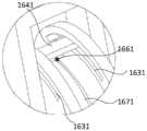
本申请所提供的融合器把持器械中,如图3~5,所述第三驱动组件16包括圆盘161和与圆盘161中心铰接的第三驱动部162,如图1或5,所述圆盘161上分别设有相对圆盘中心中心对称的第一滑槽1631和第二滑槽1632,所述第三驱动部162上设有可沿第一滑槽1631滑动的第一滑块1641以及可沿第二滑槽1632滑动的第二滑块1642;如图8,所述第一滑块1641与所述第一传动部181连接;所述第二滑块1642与所述第二传动部182连接;所述第一传动部181和第二传动部182位于外杆中的部分的运动轨迹相反。第三驱动部162可以通过驱动第一传动部181和第二传动部182反向运动,进而控制第三柔性部142的弯曲,并带动第一柔性部111、第二柔性部132随着第三柔性部142一同弯曲。In the fusion device holding instrument provided in the present application, as shown in Figures 3 to 5, the
在一些实施例中,如图8,所述第一滑块1641上设有第一卡接孔1651,所述第一卡接孔1651内设有第一传动固位件1661,所述第一传动部181与第一传动固位件1661连接、且通过第一卡接孔1651卡接;如图5,所述圆盘161上还设有第三滑槽1671;所述第一传动部181可随第一传动固位件1661沿第三滑槽1671滑动。In some embodiments, as shown in FIG. 8 , the first sliding
在一些实施例中,如图8,所述第二滑块1642上设有第二卡接孔1652,所述第二卡接孔1652内设有第二传动固位件1662,所述第二传动部182与第二传动固位件1662连接、且通过第二卡接孔1652卡接;如图5,所述圆盘161上还设有第四滑槽1672,所述第二传动部182可随第二传动固位件1662沿第四滑槽1672滑动。In some embodiments, as shown in FIG. 8 , the second sliding
在一些实施例中,第一传动部181和第二传动部182例如可以是沿外杆143的轴向方向对称分布的第一导丝和第二导丝。第一导丝和第二导丝的一端分别对称固定在第一柔性部111靠近夹持头141的端部,然后第一传动部181例如第一导丝通过第三柔性部142和外杆143上的第一传动部穿过孔191,与另一端的第一传动固位件1661连接。第二传动部182例如导丝通过第三柔性部142和外杆143上的第二传动部穿过孔192,与另一端的第二传动固位件1662连接。第一传动固位件1661例如可以是第一钢球。第一钢球通过第一卡接孔1651卡接在第三驱动部162的第一滑块1641上。第二传动固位件1662例如可以是第二钢球。第二钢球通过第二卡接孔1652卡接在第三驱动部162的第二滑块1642上。第三驱动部162例如可以是操作手柄,例如推动操作手柄朝向远离夹持头的方向运动,所述第一滑块1641可以沿着第一滑槽1631顺时针滑动,同时所述第一卡接孔1651推动第一钢球在第三滑槽1671上顺时针滑动,所述的第一钢球固定在所述的第一导丝上,第一钢球滑动时,拉扯第一导丝朝向远离夹持头的方向运动。同时所述第二滑块1642可以沿着第二滑槽1632顺时针滑动,同时所述第二卡接孔1652推动第二钢球在第四滑槽1672上顺时针滑动,所述的第二钢球固定在所述的第二导丝上,第二钢球滑动时,第二导丝朝向夹持头的方向运动,即第一导丝和第二导丝位于外杆中的运动方向相反,从而可以通过第一导丝和第二导丝控制第三柔性部142的弯曲作动,并带动第一柔性部111、第二柔性部132随着第三柔性部142一同弯曲。In some embodiments, the
优选的,第一滑槽1631、第二滑槽1632、第三滑槽1671、第四滑槽1672都是圆弧形滑槽,且均与圆盘161同心。第一滑槽1631可以包括两个第一子滑槽,第一滑块1641卡设在两个第一子滑槽中间,第一滑块1641可以沿着两个第一子滑槽滑动。同样,第二滑槽1632也可以包括两个第二子滑槽,第二滑块1642卡设在两个第二子滑槽中间,第二滑块1642可以沿着第二子滑槽滑动。更优选的,第三滑槽1671设于两个第一子滑槽中间,与两个第一子滑槽间隔设置,且延伸方向与两个第一子滑槽一致。第四滑槽1672设于两个第二子滑槽中间,与两个第二子滑槽间隔设置,且延伸方向与两个第二子滑槽一致。Preferably, the
本申请所提供的融合器把持器械中,所述的第一卡接孔1651内径大于第一导丝外径,第二卡接孔1652内径大于第二导丝外径,第一卡接孔1651内径小于第一钢球球径,第二卡接孔1652内径小于第二钢球球径。第一卡接孔1651和第二卡接孔1652的内径例如可以是0.5mm~2mm。第一导丝和第二导丝的外径可以为0.5mm~2mm。第一钢球和第二钢球的直径可以为0.8mm~2.4mm。In the cage holding instrument provided in this application, the inner diameter of the first snap-
第一传动部穿过孔191与第三滑槽1671远离夹持头141的一端对接,构成所述第一导丝安装及滑动的连续路径。第二传动部穿过孔192与第四滑槽1672远离夹持头141的一端对接,构成所述第二导丝安装及滑动的连续路径。所述的第一钢球在第三滑槽1671滑动的距离即为第一导丝拉扯滑动的长度,同时第一钢球在第三滑槽1671滑动的距离为操作手柄绕圆盘161旋转的角度与第三滑槽1671半径的乘积。所述的第二钢球在第四滑槽1672滑动的距离即为第二导丝拉扯滑动的长度,同时第二钢球在第四滑槽1672滑动的距离为操作手柄绕圆盘161旋转的角度与第四滑槽1672半径的乘积。The first transmission part passes through the
本申请所提供的融合器把持器械中,如图6,所述圆盘161上设有角度刻度标识168,用于标识第三柔性部142弯曲角度。In the cage holding instrument provided in the present application, as shown in FIG. 6 , the
本申请所提供的融合器把持器械中,如图7,所述的第三柔性部142由3—8个圆柱薄片通过弹片连接组成,其中弹片长度方向与一对导丝所在平面垂直。从而使得弯曲稳定可靠,弯曲后的外杆143轴线所在面法线始终平行两导丝所在面法线。第三柔性部的长度例如可以是5mm~15mm。In the cage holding instrument provided in the present application, as shown in FIG. 7 , the third
在一些实施例中,第二柔性部132的长度例如可以是8mm~20mm。第一柔性部111的长度例如可以是10mm~25mm。In some embodiments, the length of the second
如图9所示,本申请另一方面提供一种植入器械组件,包括本申请第一方面所述的融合器把持器械11和与所述融合器把持器械11相配合的融合器2,所述融合器2包括融合器本体21,所述融合器本体21上设有与夹持组件131配合的卡接槽22以及与芯轴11配合的第二螺纹孔23。针对椎间融合手术,把持融合器2以宽度方向通过终板外缘的间隙,并能在椎间稳定旋转,实现融合器2达到理想植入位置,提高术后恢复效果。本发明针对TLIF手术,融合器把持器械1可用于完成融合器的稳定植入,并能调整融合器在锥体之间角度,实现融合器达到理想植入位置,提高术后恢复效果。As shown in FIG. 9 , another aspect of the present application provides an implant instrument assembly, including the fusion
本申请所提供的植入器械组件中,第二螺纹孔23的孔径例如可以为2mm~5mm、2mm~3mm、3mm~4mm、或4mm~5mm等。In the implant device assembly provided in the present application, the diameter of the second threaded
本申请所提供的植入器械组件中,使用时,首先通过旋转第二驱动组件15推动外杆143朝向夹持组件131运动,使得夹持头141挤压夹持组件131向内收缩,夹持组件131与融合器的卡接槽22对接并形成夹持;然后旋转第一驱动组件12将芯轴11的第一螺纹段112拧入所述的融合器的第二螺纹孔23中。再后将融合器置入目标椎间,通过第三驱动组件16,推动操作手柄,所述第一滑块1641可以沿着第一滑槽1631滑动,同时所述第一卡接孔1651推动第一传动固位件1661在第三滑槽1671上滑动,所述的第一传动部181固定在所述第一传动固位件1661上,第一传动固位件1661滑动时,拉扯第一传动部181运动,所述第二滑块1642可以沿着第二滑槽1632滑动,同时所述第二卡接孔1652推动第二传动固位件1662在第四滑槽1672上滑动,所述的第二传动部182固定在所述第二传动固位件1662上,第二传动固位件1662滑动时,第二传动部182与第一传动部181反向运动,例如第一传动部181朝向远离夹持头的方向运动时,第二传动部182朝向夹持头方向运动,从而可以通过第一传动部181和第二传动部182控制第三柔性部142的弯曲作动,并带动第一柔性部111、第二柔性部132随着第三柔性部142一同弯曲,实现融合器放置角度的调整,从而使融合器达理想的植入位置。退出时,首先反向旋转第一驱动组件12使得芯轴11的第二螺纹段152退出所述的融合器的第二螺纹孔23,然后反向旋转第二驱动组件15,抓臂1312松开,释放融合器,最后通过第三驱动组件16使融合器把持器的第一柔性部111、第二柔性部132、第三柔性部142伸直,退出患处椎间。In the implant instrument assembly provided by the present application, when in use, firstly, the
综上,本发明的实施例所提供的融合器把持器械,通过体外第三驱动组件16调整椎间融合器角度,可使得融合器达到理想植入位置,融合器与锥体匹配更好,增加融合器的撑开效果,提高患者生理弯曲恢复效果。通过夹持和螺纹连接两种方式固定放置融合器,无需过度拧紧螺纹造成滑丝的风险,同时防止使用时螺纹松动,减少融合器植入椎间后无法摆正的风险,尤其对一些宽度小于高度的融合器,由于锥体终板为凹面,两终板中间间隙大,外缘间隙小,医生通过竖向置入融合器于椎间后,再旋转90°放横的情况,单独螺纹连接,由于椎间无视野,无法有效确定融合器在椎间的旋转状态,且旋转90°可能发生螺纹的滑丝及松动,本发明的实施例抓臂1312限制了融合器相对融合器把持器的轴向转动,可明确融合器在椎间的状态,并且能有效防止滑丝或松动,具有把持稳定,安全有效等优点。To sum up, the fusion cage holding instrument provided by the embodiment of the present invention can adjust the angle of the intervertebral fusion cage through the
综上,本申请有效克服了现有技术中的种种缺点而具高度产业利用价值。To sum up, the present application effectively overcomes various shortcomings in the prior art and has high industrial application value.
上述实施例仅例示性说明本申请的原理及其功效,而非用于限制本申请。任何熟悉此技术的人士皆可在不违背本申请的精神及范畴下,对上述实施例进行修饰或改变。因此,举凡所属技术领域中具有通常知识者在未脱离本申请所揭示的精神与技术思想下所完成的一切等效修饰或改变,仍应由本申请的权利要求所涵盖。The above-mentioned embodiments are only illustrative to illustrate the principles and effects of the present application, but are not intended to limit the present application. Any person familiar with the technology can modify or change the above-mentioned embodiments without departing from the spirit and scope of the present application. Therefore, all equivalent modifications or changes made by those skilled in the art without departing from the spirit and technical ideas disclosed in the application shall still be covered by the claims of the application.
Claims (10)
Translated fromChinesePriority Applications (1)
| Application Number | Priority Date | Filing Date | Title |
|---|---|---|---|
| CN202111599693.7ACN116327455B (en) | 2021-12-24 | 2021-12-24 | Fusion device holding instrument |
Applications Claiming Priority (1)
| Application Number | Priority Date | Filing Date | Title |
|---|---|---|---|
| CN202111599693.7ACN116327455B (en) | 2021-12-24 | 2021-12-24 | Fusion device holding instrument |
Publications (2)
| Publication Number | Publication Date |
|---|---|
| CN116327455Atrue CN116327455A (en) | 2023-06-27 |
| CN116327455B CN116327455B (en) | 2025-08-19 |
Family
ID=86879441
Family Applications (1)
| Application Number | Title | Priority Date | Filing Date |
|---|---|---|---|
| CN202111599693.7AActiveCN116327455B (en) | 2021-12-24 | 2021-12-24 | Fusion device holding instrument |
Country Status (1)
| Country | Link |
|---|---|
| CN (1) | CN116327455B (en) |
Citations (4)
| Publication number | Priority date | Publication date | Assignee | Title |
|---|---|---|---|---|
| US20120323327A1 (en)* | 2011-06-17 | 2012-12-20 | Mcafee Paul C | Expandable Spinal Implant and Flexible Driver |
| WO2019179988A1 (en)* | 2018-03-19 | 2019-09-26 | Medicrea International | Assembly comprising an intervertebral implant of the tlif type and an instrument for the placement of said implant |
| CN113599029A (en)* | 2021-07-26 | 2021-11-05 | 北京纳通医疗科技控股有限公司 | Pushing device |
| CN216439377U (en)* | 2021-12-24 | 2022-05-06 | 影为医疗科技(上海)有限公司 | Fusion cage holding instrument and implantation instrument assembly |
- 2021
- 2021-12-24CNCN202111599693.7Apatent/CN116327455B/enactiveActive
Patent Citations (4)
| Publication number | Priority date | Publication date | Assignee | Title |
|---|---|---|---|---|
| US20120323327A1 (en)* | 2011-06-17 | 2012-12-20 | Mcafee Paul C | Expandable Spinal Implant and Flexible Driver |
| WO2019179988A1 (en)* | 2018-03-19 | 2019-09-26 | Medicrea International | Assembly comprising an intervertebral implant of the tlif type and an instrument for the placement of said implant |
| CN113599029A (en)* | 2021-07-26 | 2021-11-05 | 北京纳通医疗科技控股有限公司 | Pushing device |
| CN216439377U (en)* | 2021-12-24 | 2022-05-06 | 影为医疗科技(上海)有限公司 | Fusion cage holding instrument and implantation instrument assembly |
Also Published As
| Publication number | Publication date |
|---|---|
| CN116327455B (en) | 2025-08-19 |
Similar Documents
| Publication | Publication Date | Title |
|---|---|---|
| US12433763B2 (en) | Expandable interbody device | |
| US12109127B2 (en) | Implant inserter having a laterally-extending dovetail engagement feature | |
| US6569168B2 (en) | Intervertebral distractor and implant insertion instrument | |
| CN106073950B (en) | Implanting instrument for spinal fusion operation and intervertebral fusion device thereof | |
| JP5020262B2 (en) | Device for inserting a rod into a patient | |
| US10806598B2 (en) | Implant inserter | |
| JP6028028B2 (en) | Medical equipment | |
| US20080065082A1 (en) | Steerable rasp/trial inserter | |
| US20070142843A1 (en) | Articulated delivery instrument | |
| JP2022535698A (en) | Bone ties and bone tie inserters | |
| WO2008131084A2 (en) | Minimally open interbody access retraction device and surgical method | |
| EP2774564B1 (en) | Percutaneous rod inserter | |
| WO2013008176A1 (en) | Retractor tool | |
| CN102860888A (en) | Integral lumbar intervertebral titanium plate fusion apparatus | |
| WO2015200018A1 (en) | Flexible spinal driver or drill with a malleable core, and/or fixed core radius | |
| CN107518966B (en) | Intervertebral disc prosthesis holder | |
| CN108969161B (en) | A kind of intervertebral motion retention device, positioning implantation device and implantation method thereof | |
| CN100358484C (en) | Device for fusing vertebrae | |
| CN116327455A (en) | A fusion device holding instrument | |
| CN216439377U (en) | Fusion cage holding instrument and implantation instrument assembly | |
| CN116350408A (en) | A kind of holding instrument and fusion device assembly | |
| US20230270428A1 (en) | Devices, systems, and methods for inserting and removing surgical wires | |
| CN217853200U (en) | An angle-adjustable blue forceps and surgical instrument bag | |
| CN108969160A (en) | A kind of intervertebral motion retaining device and its integral type implantation instrument and method for implantation | |
| CN208989266U (en) | intervertebral disc prosthesis holder |
Legal Events
| Date | Code | Title | Description |
|---|---|---|---|
| PB01 | Publication | ||
| PB01 | Publication | ||
| SE01 | Entry into force of request for substantive examination | ||
| SE01 | Entry into force of request for substantive examination | ||
| GR01 | Patent grant | ||
| GR01 | Patent grant |