CN116325028A - Wire harness - Google Patents
Wire harnessDownload PDFInfo
- Publication number
- CN116325028A CN116325028ACN202180067762.1ACN202180067762ACN116325028ACN 116325028 ACN116325028 ACN 116325028ACN 202180067762 ACN202180067762 ACN 202180067762ACN 116325028 ACN116325028 ACN 116325028A
- Authority
- CN
- China
- Prior art keywords
- end portion
- path
- restricting member
- connecting portion
- path restricting
- Prior art date
- Legal status (The legal status is an assumption and is not a legal conclusion. Google has not performed a legal analysis and makes no representation as to the accuracy of the status listed.)
- Pending
Links
Images


Classifications
- B—PERFORMING OPERATIONS; TRANSPORTING
- B60—VEHICLES IN GENERAL
- B60R—VEHICLES, VEHICLE FITTINGS, OR VEHICLE PARTS, NOT OTHERWISE PROVIDED FOR
- B60R16/00—Electric or fluid circuits specially adapted for vehicles and not otherwise provided for; Arrangement of elements of electric or fluid circuits specially adapted for vehicles and not otherwise provided for
- B60R16/02—Electric or fluid circuits specially adapted for vehicles and not otherwise provided for; Arrangement of elements of electric or fluid circuits specially adapted for vehicles and not otherwise provided for electric constitutive elements
- B60R16/0207—Wire harnesses
- B60R16/0215—Protecting, fastening and routing means therefor
- H—ELECTRICITY
- H01—ELECTRIC ELEMENTS
- H01B—CABLES; CONDUCTORS; INSULATORS; SELECTION OF MATERIALS FOR THEIR CONDUCTIVE, INSULATING OR DIELECTRIC PROPERTIES
- H01B7/00—Insulated conductors or cables characterised by their form
- H—ELECTRICITY
- H02—GENERATION; CONVERSION OR DISTRIBUTION OF ELECTRIC POWER
- H02G—INSTALLATION OF ELECTRIC CABLES OR LINES, OR OF COMBINED OPTICAL AND ELECTRIC CABLES OR LINES
- H02G3/00—Installations of electric cables or lines or protective tubing therefor in or on buildings, equivalent structures or vehicles
- H02G3/02—Details
- H02G3/04—Protective tubing or conduits, e.g. cable ladders or cable troughs
- H02G3/0406—Details thereof
- H02G3/0412—Heat or fire protective means
- H—ELECTRICITY
- H02—GENERATION; CONVERSION OR DISTRIBUTION OF ELECTRIC POWER
- H02G—INSTALLATION OF ELECTRIC CABLES OR LINES, OR OF COMBINED OPTICAL AND ELECTRIC CABLES OR LINES
- H02G3/00—Installations of electric cables or lines or protective tubing therefor in or on buildings, equivalent structures or vehicles
- H02G3/02—Details
- H02G3/04—Protective tubing or conduits, e.g. cable ladders or cable troughs
- H02G3/0462—Tubings, i.e. having a closed section
- H02G3/0468—Corrugated
Landscapes
- Engineering & Computer Science (AREA)
- Architecture (AREA)
- Civil Engineering (AREA)
- Structural Engineering (AREA)
- Mechanical Engineering (AREA)
- Details Of Indoor Wiring (AREA)
- Insulated Conductors (AREA)
Abstract
Translated fromChinese
Description
Translated fromChinese技术领域technical field
本公开涉及一种线束。The present disclosure relates to a wire harness.
背景技术Background technique
现今,已知一种线束,该线束具备覆盖电线部件的外周的波纹管、以及覆盖波纹管的周向的一部分且对布设电线部件的路径进行限制的路径限制部件(例如参照专利文献1)。Conventionally, a wire harness is known that includes a corrugated tube covering the outer periphery of an electric wire component, and a path restricting member covering a part of the corrugated tube in the circumferential direction and restricting a route in which the electric wire component is laid (for example, refer to Patent Document 1).
专利文献1所记载的线束中的波纹管具有沿长度方向形成的狭缝。路径限制部件具备沿波纹管的外周设置的路径维持部件和设置在狭缝内的安装部件。安装部件构成为能够分别卡止于狭缝的内周侧部分和路径维持部件的外周侧部分。上述波纹管、路径维持部件、以及安装部件通过带卷绕等被固定,由此限制电线部件的路径。The corrugated tube in the wire harness described in Patent Document 1 has slits formed in the longitudinal direction. The path restricting member includes a path maintaining member provided along the outer periphery of the bellows and an attachment member provided in the slit. The attachment member is configured to be lockable to the inner peripheral side portion of the slit and the outer peripheral side portion of the path maintaining member, respectively. The above-mentioned corrugated tube, path maintaining member, and mounting member are fixed by tape winding or the like, thereby restricting the path of the electric wire member.
现有技术文献prior art literature
专利文献patent documents
专利文献1:日本特开2013-55760号公报Patent Document 1: Japanese Unexamined Patent Publication No. 2013-55760
发明内容Contents of the invention
发明要解决的课题The problem to be solved by the invention
然而,在专利文献1所记载的线束中,安装部件设置在波纹管的狭缝内。因此,有在安装部件与狭缝之间产生缝隙的担忧。这样的缝隙在提高线束的止水性方面不推荐。However, in the wire harness described in Patent Document 1, the mounting member is provided in the slit of the corrugated tube. Therefore, there is a concern that a gap may be generated between the mounting member and the slit. Such gaps are not recommended for improving the water-tightness of the wiring harness.
本公开的目的在于提供一种能够抑制止水性的降低的线束。An object of the present disclosure is to provide a wire harness capable of suppressing a decrease in waterproofness.
用于解决课题的方案Solution to the problem
本公开的线束具备:电线部件;筒状的外装部件,其覆盖所述电线部件的外周;以及路径限制部件,其覆盖所述外装部件的外周当中所述外装部件的周向的一部分,并且沿所述外装部件的长度方向延伸,对布设所述电线部件的路径进行限制,所述路径限制部件具有:插入口,其沿所述路径限制部件的长度方向并遍及所述路径限制部件的全长地延伸,是构成为能够插入所述外装部件的开口;第一端部及第二端部,所述第一端部及所述第二端部在所述路径限制部件的周向上相互位于相反侧,并形成所述插入口;以及连结部,其将所述第一端部和所述第二端部连结,从所述路径限制部件的所述长度方向观察时的所述连结部的形状呈圆弧形状,该圆弧是以沿着所述路径限制部件的长度方向的轴上的点为中心的假想圆的一部分,所述连结部具有比所述外装部件大的曲率半径,所述第一端部以及所述第二端部向所述假想圆的内侧弯折而与所述外装部件的外表面接触。The wire harness of the present disclosure includes: an electric wire member; a cylindrical outer covering member covering the outer periphery of the electric wire member; and a path regulating member covering a part of the outer periphery of the outer covering member in the circumferential direction of the outer covering member and The exterior member extends in the longitudinal direction and restricts a route for routing the electric wire member, and the route restricting member has an insertion opening along the longitudinal direction of the route restricting member and over the entire length of the route restricting member. extending to be configured to be able to be inserted into the opening of the exterior member; a first end portion and a second end portion, the first end portion and the second end portion are opposite to each other in the circumferential direction of the path restricting member side, and form the insertion port; and a connecting portion, which connects the first end portion and the second end portion, the shape of the connecting portion when viewed from the longitudinal direction of the path restricting member In the shape of an arc, the arc is a part of an imaginary circle centered at a point on the axis along the longitudinal direction of the path limiting member, the connecting portion has a larger radius of curvature than the outer covering member, and the The first end portion and the second end portion are bent inwardly of the imaginary circle to be in contact with the outer surface of the exterior member.
发明的效果The effect of the invention
根据本公开,能够抑制线束的止水性的降低。According to the present disclosure, it is possible to suppress a decrease in the waterproofness of the wire harness.
附图说明Description of drawings
图1是示出一个实施方式的线束的概要构成图。FIG. 1 is a schematic configuration diagram showing a wire harness according to one embodiment.
图2是示出一个实施方式的线束的剖视图。FIG. 2 is a cross-sectional view showing a wire harness according to one embodiment.
图3是分解地示出一个实施方式的线束中的外装部件和路径限制部件的分解立体图。Fig. 3 is an exploded perspective view showing a sheath member and a path restricting member in the wire harness according to one embodiment in an exploded manner.
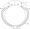
图4是示出一个实施方式的路径限制部件的主视图。Fig. 4 is a front view showing a path restricting member of one embodiment.
图5是示出变形例的路径限制部件的主视图。Fig. 5 is a front view showing a path regulating member of a modified example.
图6是示出变形例的路径限制部件的主视图。Fig. 6 is a front view showing a path regulating member of a modified example.
具体实施方式Detailed ways
[本公开的实施方式的说明][Description of Embodiments of the Present Disclosure]
首先,列举本公开的实施方式进行说明。First, embodiments of the present disclosure will be described.
本公开的线束构成为,The wiring harness of the present disclosure is constituted as,
[1]线束具备:电线部件;筒状的外装部件,其覆盖所述电线部件的外周;以及路径限制部件,其覆盖所述外装部件的外周当中所述外装部件的周向的一部分,并且沿所述外装部件的长度方向延伸,对布设所述电线部件的路径进行限制,所述路径限制部件具有:插入口,其沿所述路径限制部件的长度方向并遍及所述路径限制部件的全长地延伸,所述插入口是构成为能够插入所述外装部件的开口;第一端部及第二端部,所述第一端部及所述第二端部在所述路径限制部件的周向上相互位于相反侧,并形成所述插入口;以及连结部,其将所述第一端部和所述第二端部连结,从所述路径限制部件的所述长度方向观察时的所述连结部的形状呈圆弧形状,该圆弧是以沿着所述路径限制部件的长度方向的轴上的点为中心的假想圆的一部分,所述连结部具有比所述外装部件大的曲率半径,所述第一端部以及所述第二端部向所述假想圆的内侧弯折而与所述外装部件的外表面接触。[1] The wiring harness includes: an electric wire member; a cylindrical outer covering member covering the outer periphery of the electric wire member; and a path restricting member covering a part of the outer periphery of the outer covering member in the circumferential direction of the outer covering member and The exterior member extends in the longitudinal direction and restricts a route for routing the electric wire member, and the route restricting member has an insertion opening along the longitudinal direction of the route restricting member and over the entire length of the route restricting member. The insertion port is an opening configured to be inserted into the exterior member; a first end portion and a second end portion, and the first end portion and the second end portion are on the periphery of the path restricting member. upwardly located on opposite sides of each other, and forming the insertion port; and a connecting portion that connects the first end portion and the second end portion, the The connecting portion has a shape of an arc which is a part of an imaginary circle centered at a point on an axis along the longitudinal direction of the path restricting member, and the connecting portion has a larger curvature than that of the outer covering member. The radius, the first end portion and the second end portion are bent inwardly of the imaginary circle to come into contact with the outer surface of the exterior member.
根据该结构,能够相对于外装部件的外周通过插入口后安装路径限制部件。另外,从所述路径限制部件的所述长度方向观察时的路径限制部件的连结部的形状呈圆弧形状,该圆弧是以沿着路径限制部件的长度方向的轴上的点为中心的假想圆的一部分。而且,由于设置于连结部的两端部的第一端部以及第二端部向所述假想圆的内侧弯折而与外装部件的外表面接触,所以能够抑制路径限制部件通过插入口从外装部件脱离。因此,在限制被外装部件覆盖的电线部件的路径的方面,例如不需要在外装部件形成用于将路径限制部件安装于外装部件的狭缝等。因此,能够抑制线束的止水性的降低。According to this configuration, the path regulating member can be attached to the outer periphery of the exterior member through the insertion opening. In addition, when viewed from the longitudinal direction of the path restricting member, the shape of the connecting portion of the path restricting member is an arc shape centered on a point on an axis along the longitudinal direction of the path restricting member. Part of an imaginary circle. Furthermore, since the first end portion and the second end portion provided at both ends of the connecting portion are bent inwardly of the imaginary circle and come into contact with the outer surface of the exterior member, it is possible to prevent the passage restricting member from passing through the insertion opening from Exterior parts are detached. Therefore, it is not necessary to form, for example, a slit for attaching the path regulating member to the exterior member in the exterior member in order to restrict the path of the electric wire member covered by the exterior member. Therefore, it is possible to suppress a decrease in the waterproofness of the wire harness.
[2]优选为,所述连结部的形状为优弧。[2] Preferably, the shape of the connecting portion is a major arc.
根据该结构,由于连结部的形状为优弧,所以能够设为第一端部以及第二端部容易朝向连结部的内表面侧按压外装部件的形状。According to this configuration, since the shape of the connecting portion is a curved shape, the first end portion and the second end portion can easily press the exterior member toward the inner surface side of the connecting portion.
[3]优选为,所述连结部的形状为劣弧。[3] Preferably, the shape of the connecting portion is a minor arc.
根据该结构,由于连结部的形状为劣弧,所以与呈优弧的情况相比,例如,能够增长第一端部以及第二端部的周向的长度。从而,例如能够容易扩大插入口的开口宽度。According to this configuration, since the shape of the connecting portion is a minor arc, for example, the circumferential lengths of the first end portion and the second end portion can be increased compared to a case of a major arc. Therefore, for example, the opening width of the insertion port can be easily enlarged.
[4]优选为,在从所述路径限制部件的长度方向观察时,所述连结部、所述第一端部以及所述第二端部的厚度恒定。[4] Preferably, the connecting portion, the first end portion, and the second end portion have constant thicknesses when viewed in the longitudinal direction of the path regulating member.
根据该结构,由于在从路径限制部件的长度方向观察时,连结部、第一端部以及第二端部的厚度恒定,所以例如设计变得容易。另外,例如在路径限制部件由金属制成的情况下,能够容易从金属板材进行制造。According to this configuration, since the thicknesses of the connecting portion, the first end portion, and the second end portion are constant when viewed from the longitudinal direction of the path regulating member, for example, design becomes easy. In addition, for example, when the path restricting member is made of metal, it can be easily manufactured from a sheet metal material.
[5]优选为,所述连结部具有沿所述路径限制部件的长度方向延伸且在所述连结部的径向上突出的突出部。[5] Preferably, the connecting portion has a protruding portion extending in the longitudinal direction of the path restricting member and protruding in a radial direction of the connecting portion.
根据该结构,由于连结部具有沿路径限制部件的长度方向延伸且在连结部的径向上突出的突出部,所以能够提高路径限制部件的弯曲刚性。According to this configuration, since the connecting portion has the protruding portion extending in the longitudinal direction of the path regulating member and projecting in the radial direction of the connecting portion, the bending rigidity of the path regulating member can be improved.
[6]优选为,所述路径限制部件由树脂制成,并且从所述路径限制部件的长度方向观察时的截面形状恒定。[6] Preferably, the path restricting member is made of resin, and has a constant cross-sectional shape when viewed in a longitudinal direction of the path restricting member.
根据该结构,由于路径限制部件由树脂制成,并且从所述路径限制部件的长度方向观察时的截面形状恒定,所以例如能够通过挤出成形而容易地制造。According to this configuration, since the path regulating member is made of resin and has a constant cross-sectional shape when viewed in the longitudinal direction of the path regulating member, it can be easily manufactured by, for example, extrusion molding.
[7]优选为,所述路径限制部件由金属制成。[7] Preferably, the path restricting member is made of metal.
根据该结构,由于路径限制部件由金属制成,所以例如在配置于离车辆的热源较近的位置的情况等下,能够抑制外装部件的内部的温度、以及电线部件的温度上升。According to this configuration, since the path restricting member is made of metal, for example, when it is disposed near a heat source of the vehicle, it is possible to suppress an increase in the temperature inside the exterior member and the temperature of the wire member.
[8]优选为,所述外装部件是具有挠性并遍及所述外装部件的整个周向被封闭的波纹管。[8] Preferably, the exterior member is a flexible bellows that is closed over the entire circumference of the exterior member.
根据该结构,能够根据电线部件的布线路径使外装部件变形。另外,由于外装部件遍及整个周向被封闭,所以能够提高外装部件的止水性。因此,能够同时实现线束的布设性的提高和止水性的提高。According to this configuration, the exterior member can be deformed according to the wiring route of the electric wire member. In addition, since the exterior member is closed over the entire circumferential direction, the watertightness of the exterior member can be improved. Therefore, it is possible to achieve both the improvement of the laying properties of the wire harness and the improvement of the waterproofness.
[本公开的实施方式的详细内容][Details of Embodiments of the Present Disclosure]
以下,参照附图对本公开的线束的具体例进行说明。在各附图中,为了便于说明,有时夸张或简化地示出结构的一部分。另外,有时各部分的尺寸比率在各附图中不同。另外,本公开不限于这些示例,而是指由权利要求书示出,意图包含与权利要求书均等的含义以及范围内的所有变更。本说明书中的“正交”不仅包含严格地正交的情况,还包含在起到本实施方式的作用效果的范围内大致正交的情况。另外,本说明书中的“圆”、“圆弧”不仅包含严格地呈圆、圆弧的情况,还包含在起到本实施方式的作用效果的范围内大致呈圆、圆弧的情况。Hereinafter, specific examples of the wire harness of the present disclosure will be described with reference to the drawings. In each drawing, a part of the structure may be exaggerated or simplified for convenience of description. In addition, the dimensional ratio of each part may differ in each drawing. In addition, this indication is not limited to these examples but is shown by a claim, and it is intended that the meaning of a claim and equality and all the changes within a range are included. The term "orthogonal" in this specification includes not only strictly orthogonal but also substantially orthogonal within the scope of achieving the effects of the present embodiment. In addition, the "circle" and "arc" in this specification include not only the cases of strictly circles and arcs, but also the cases of substantially circles and arcs within the range of exerting the effect of the present embodiment.
(线束10整体结构)(Overall structure of wiring harness 10)
图1所示的线束10将两个或三个以上的电气设备电连接。线束10例如将设置于混合动力车、电动汽车等车辆V的前部的逆变器11和设置于比该逆变器11靠车辆V的后方的位置的高压电池12电连接。线束10例如布设为在车辆V的地板下等穿过。例如,线束10的长度方向的中间部布设为在车辆V的地板下等车室外穿过。The
逆变器11与成为车辆行驶的动力源的未图示的车轮驱动用的马达连接。逆变器11从高压电池12的直流电生成交流电,并将该交流电供给至马达。高压电池12例如是能够供给几百伏的电压的电池。The inverter 11 is connected to a motor for driving wheels (not shown) that serves as a power source for running the vehicle. The inverter 11 generates AC power from the DC power of the high-
如图1及图2所示,线束10具备将上述电气设备彼此电连接的电线部件20、覆盖电线部件20的外周的筒状的外装部件30、以及覆盖外装部件30的外周且限制布设电线部件20的路径(以下称作布线路径)的路径限制部件40。在电线部件20的两端部安装有一对连接器C1、C2。As shown in FIGS. 1 and 2 , the
(电线部件20的结构)(Structure of the electric wire part 20)
电线部件20具有一根或多根电线21和一并地覆盖各电线21的外周的编织部件24。本实施方式的电线部件20具有两根电线21。电线部件20的一端部经由连接器C1而与逆变器11连接,电线部件20的另一端部经由连接器C2而与高压电池12连接。电线部件20例如以沿车辆的前后方向延伸的方式形成为长条状。电线21例如是能够与高电压、大电流对应的高压电线。电线21例如可以是自身不具有电磁屏蔽构造的非屏蔽电线,也可以是自身具有电磁屏蔽构造的屏蔽电线。The
(电线21的结构)(Structure of wire 21)
如图2所示,电线21是具有由导体构成的芯线22和包覆芯线22的外周的绝缘包覆部23的包覆电线。As shown in FIG. 2 , the
(芯线22的结构)(Structure of core wire 22)
作为芯线22,例如能够使用将多个金属线材绞合而成的绞线、由内部为实心构造的柱状的一根金属棒构成的柱状导体、内部为中空构造的筒状导体等。另外,作为芯线22,例如也能够使用将绞线、柱状导体、筒状导体等多种导体组合而成的芯线。作为柱状导体,例如能够举出单芯线、母线等。本实施方式的芯线22是绞线。作为芯线22的材料,例如能够使用铜系、铝系等金属材料。As the
由与芯线22的长度方向、即电线21的长度方向正交的平面将芯线22剖切而得到的截面形状(以下称作横截面形状)能够设为任意形状。芯线22的横截面形状例如形成为圆形、半圆形、多边形、正方形、扁平形状等。本实施方式的芯线22的横截面形状形成为圆形。The cross-sectional shape of the
本说明书中的“扁平形状”例如包含长方形、长圆形、椭圆形等。另外,本说明书中的“长方形”具有长边和短边,并非正方形。另外,本说明书中的“长方形”也包含对棱角部进行倒角后的形状、使棱角部变圆的形状。本说明书中的“长圆形”是由两个大致相等的长度的平行线和两个半圆形构成的形状。The "flat shape" in this specification includes a rectangle, an oblong shape, an ellipse, etc., for example. In addition, the "rectangle" in this specification has a long side and a short side, and is not a square. In addition, the "rectangular shape" in this specification also includes the shape which chamfered the corner part, and the shape which rounded the corner part. The "oblong circle" in this specification is a shape constituted by two parallel lines of approximately equal length and two semicircles.
(绝缘包覆部23的结构)(Structure of the insulating covering portion 23)
绝缘包覆部23例如遍及整周地包覆芯线22的外周面。绝缘包覆部23例如由合成树脂等绝缘材料构成。作为绝缘包覆部23的材料,例如能够使用以交联聚乙烯、交联聚丙烯等聚烯烃系树脂为主成分的合成树脂。另外,作为绝缘包覆部23的材料,可以单独地使用一种材料,也可以适当组合两种以上的材料来使用。The insulating
(编织部件24的结构)(Structure of knitted component 24)
编织部件24例如整体呈一并地覆盖各电线21的外周的筒状。编织部件24例如设置为遍及电线21的大致全长地覆盖各电线21的外周。作为编织部件24,能够使用将多个金属线材编织成的编织线、将金属线材和树脂线材组合而编织成的编织线。作为金属线材的材料,例如能够使用铜系、铝系等金属材料。作为树脂线材,例如能够使用对位芳纶纤维等绝缘性以及耐剪切性优异的强化纤维。虽省略图示,但编织部件24例如在各连接器C1、C2等中接地。The
(外装部件30的结构)(Structure of exterior member 30)
如图3所示,外装部件30呈遍及整个周向地覆盖电线部件20的外周的圆筒状。外装部件30遍及整个周向被封闭。外装部件30例如设置为包覆电线部件20的长度方向的一部分外周。本实施方式的外装部件30是具有沿长度方向交替地相连设置有环状凸部31和环状凹部32的波纹构造的波纹管。外装部件30具有挠性。As shown in FIG. 3 , the
作为外装部件30的材料,例如能够使用具有导电性的树脂材料、不具有导电性的树脂材料。作为树脂材料,例如能够使用聚烯烃、聚酰胺、聚酯、ABS树脂等合成树脂。As the material of the
(路径限制部件40的结构)(Structure of path restricting member 40)
如图2及图3所示,路径限制部件40覆盖外装部件30的外周中的外装部件30的周向的一部分,并且沿外装部件30的长度方向延伸。另外,路径限制部件40覆盖比外装部件30的外周的一半部分大的范围。本实施方式的路径限制部件40例如安装于电线部件20的布线路径中的车辆V的地板下等的外装部件30呈直线状地延伸的部分的外周。As shown in FIGS. 2 and 3 , the
路径限制部件40由树脂制成。作为路径限制部件40的材料,例如能够使用聚丙烯、聚酰胺、聚甲醛等合成树脂。路径限制部件40例如能够通过挤出成形、注射成形等公知的制造方法来制造。本实施方式的路径限制部件40的从路径限制部件40的长度方向观察到的截面形状恒定。路径限制部件40是挤出成形品。The
路径限制部件40具有沿路径限制部件40的长度方向延伸的插入口44、在与路径限制部件40的长度方向正交的方向上分离并形成插入口44的第一端部41及第二端部42、以及将第一端部41及第二端部42连结的连结部43。换言之,路径限制部件40具有形成为覆盖外装部件30的周向的一部分的连结部43、设置于连结部43的两端部的第一端部41及第二端部42、以及由第一端部41及第二端部42形成的插入口44。The
第一端部41和第二端部42在路径限制部件40的周向上相互位于相反侧。第一端部41和第二端部42在路径限制部件40的周向上隔着插入口44而相互分离。The
连结部43形成为比外装部件30大的曲率半径的圆弧形状。详细而言,如图4所示,从路径限制部件40的长度方向观察时的连结部43的形状为形成以沿着路径限制部件40的长度方向的轴上的点A为中心的第一假想圆Z的一部分的圆弧。沿着路径限制部件40的长度方向的轴上的点A能够称作沿着路径限制部件40的长度方向的轴,并且能够称作与路径限制部件40平行的假想直线。连结部43具有比外装部件30大的曲率半径。The connecting
本实施方式的连结部43的形状为优弧。即,在以2点将第一假想圆Z分为两个部分时,连结部43的形状为长度比整周的一半大的形状。The shape of the connecting
换言之,如图4所示,当将穿过点A和连结部43的一方端部的直线设为直线K1、将穿过点A和连结部43的另一方端部的直线设为直线K2时,连结部43所处的一侧的直线K1与直线K2所成的角度θ1比180°大。In other words, as shown in FIG. 4 , when a straight line passing through point A and one end of the connecting
如图4所示,当从路径限制部件40的长度方向观察时,第一端部41以及第二端部42构成为向第一假想圆Z的内侧弯折而与外装部件30的外表面接触。换言之,连结部43的圆弧形状为沿着第一假想圆Z的一部分的形状,以朝向该第一假想圆Z的内侧的方式从连结部43弯折地形成有第一端部41以及第二端部42。在从路径限制部件40的长度方向观察时,本实施方式的第一端部41以及第二端部42形成为圆弧形状。换言之,第一端部41以及第二端部42的形状为圆弧。在从路径限制部件40的长度方向观察时,第一端部41和第二端部42设为长度相同。在从路径限制部件40的长度方向观察时,连结部43、第一端部41以及第二端部42设为厚度恒定。As shown in FIG. 4 , when viewed from the longitudinal direction of the
插入口44沿路径限制部件40的长度方向遍及路径限制部件40的全长地延伸。插入口44的开口宽度、即第一端部41与第二端部42的最短距离比外装部件30的外径小。The
在从与长度方向正交的方向朝插入口44插入外装部件30时,路径限制部件40弹性变形而插入口44的开口宽度变大。若外装部件30被插入于路径限制部件40的内部,则路径限制部件40以欲返回至原先的形状的方式弹性复原。由此,上述开口宽度变得比外装部件30的外径小,因此在外装部件30安装路径限制部件40。另外,在外装部件30插入于路径限制部件40的内部的状态下,不限于上述开口宽度严格地返回至原先的宽度,也有时由外装部件30妨碍路径限制部件40欲返回至原先的形状的弹性变形,从而开口宽度成为比原先的宽度稍大的宽度。另外,在外装部件30插入于路径限制部件40的内部的状态下,也有时外装部件30成为挠曲的状态,由此上述开口宽度返回至原先的宽度。即,外装部件30插入于路径限制部件40的内部的状态下的上述开口宽度成为基于外装部件30、路径限制部件40的刚性、易挠曲性等的大小。另外,图2及图4中,并非严格地示出外装部件30插入于路径限制部件40的内部的状态下的外装部件30、路径限制部件40的挠曲的状态,而是示意性地示出外装部件30、路径限制部件40的状态。When the
在以下的说明中,如图4所示,在从长度方向观察时,将穿过能够收纳在路径限制部件40的内侧的最大的第二假想圆X的中心轴线C和第一端部41的前端45的直线设为直线T1,将穿过中心轴线C和第二端部42的前端46的直线设为直线T2。另外,上述第二假想圆X是在未插入外装部件30的状态下能够收纳在路径限制部件40的内侧的最大直径的第二假想圆X,不限于与外装部件30的外周一致,图4中,示意性地示出一致。在本实施方式中,外装部件30的直径设定为比上述第二假想圆X的直径稍大。In the following description, as shown in FIG. 4 , when viewed from the longitudinal direction, the central axis C passing through the largest second virtual circle X that can be accommodated inside the
为了在本实施方式的外装部件30安装路径限制部件40,插入口44的打开角度θ2例如优选在60°至120°的范围内。本实施方式的打开角度θ2为70°。本说明书中的“打开角度θ2”是所述直线T1与直线T2所成的角度。In order to attach the
第一端部41的前端45沿所述直线T1形成。第二端部42的前端46沿所述直线T2形成。由此,插入口44形成为在离所述中心轴线C越远的径向外侧,开口宽度越大。The
在本实施方式的路径限制部件40中,第一端部41以及第二端部42朝向连结部43的内表面侧按压外装部件30。由此,相对于外装部件30保持路径限制部件40。In the
对本实施方式的作用进行说明。The operation of this embodiment will be described.
根据本实施方式的线束10,能够相对于外装部件30的外周通过插入口44而后安装路径限制部件40。由于路径限制部件40具有向第一假想圆Z的内侧弯折而与外装部件30的外表面接触的第一端部41以及第二端部42,所以能够抑制路径限制部件40通过插入口44从外装部件30脱离。According to the
对本实施方式的效果进行说明。Effects of this embodiment will be described.
(1)从路径限制部件40的长度方向观察时的路径限制部件40的连结部43的形状为形成以沿着路径限制部件40的长度方向的轴上的点A为中心的第一假想圆Z的一部分的圆弧。而且,由于设置于连结部43的两端部的第一端部41以及第二端部42向第一假想圆Z的内侧弯折而与外装部件30的外表面接触,所以能够抑制路径限制部件40穿过插入口44从外装部件30脱离。因此,在限制被外装部件30覆盖的电线部件20的路径的方面,例如不需要在外装部件形成用于将路径限制部件40安装于外装部件30的狭缝等。因此,能够抑制线束10的止水性的降低。(1) The shape of the connecting
(2)由于连结部43的形状为优弧,所以能够设为第一端部41以及第二端部42容易朝向连结部43的内表面侧按压外装部件30的形状。(2) Since the connecting
(3)由于在从路径限制部件40的长度方向观察时,连结部43、第一端部41以及第二端部42的厚度恒定,所以例如设计变得容易。(3) Since the thicknesses of the connecting
(4)由于路径限制部件40由树脂制成,并且从路径限制部件40的长度方向观察时的截面形状恒定,所以例如能够通过挤出成形而容易地制造。换言之,由于路径限制部件40是挤出成形品,所以能够容易地制造。(4) Since the
(5)外装部件30是波纹管。根据这样的结构,能够根据电线部件20的布线路径来使外装部件30变形。另外,由于外装部件30遍及整个周向被封闭,所以能够提高外装部件30的止水性。因此,能够同时实现线束10的布设性的提高和止水性的提高。(5) The
<变形例><Modification>
本实施方式能够如下变更来实施。本实施方式以及以下的变形例能够在技术上不产生矛盾的范围内相互组合来实施。This embodiment can be implemented by changing as follows. This embodiment and the following modified examples can be implemented in combination with each other within a range that does not cause technical contradictions.
·在上述实施方式中,连结部43的形状设为优弧,但不限于此,例如,也可以如图5所示地设为劣弧。即,在以2点将第一假想圆Z分为两个部分时,图5所示的连结部43的形状为长度比整周的一半小的形状。另外,图5中,仅用圆弧状的假想线示出以沿着路径限制部件40的长度方向的轴上的点A为中心的第一假想圆Z的一部分。- In the said embodiment, although the shape of the
换言之,如图5所示,在将穿过点A和连结部43的一方端部的直线设为直线K1、将穿过点A和连结部43的另一方端部的直线设为直线K2时,连结部43所处的一侧的直线K1与直线K2所成的角度θ1比180°小。这样的话,例如能够增长第一端部41以及第二端部42的周向的长度。从而,例如能够容易扩大插入口44的开口宽度。In other words, as shown in FIG. 5 , when a straight line passing through the point A and one end of the connecting
另外,连结部43的形状也可以设为半圆的圆弧。换言之,连结部43的形状也可以设为作为将第一假想圆Z分为相同大小时的单侧的形状的圆弧。In addition, the shape of the connecting
另外,在图4所示的上述实施方式以及图5所示的上述另一例中,设为第一假想圆Z的中心的点A位于路径限制部件40的内侧的形状的路径限制部件40,但不限于此,也可以设为点A位于路径限制部件40的外侧的形状的路径限制部件40。In addition, in the above-mentioned embodiment shown in FIG. 4 and the above-mentioned another example shown in FIG. 5 , the
·如图6所示,连结部43也可以构成为具有沿路径限制部件40的长度方向延伸且在连结部43的径向上突出的突出部47。这样的话,能够提高路径限制部件40的弯曲刚性。另外,突出部47可以构成为沿路径限制部件40的长度方向设置于路径限制部件40的全长,也可以构成为设置于路径限制部件40的长度方向的一部分。另外,设置突出部47的位置、突出部47的数量、突出部47的形状也可以变更。例如,也可以将突出部设置于连结部43与第一端部41的界线的位置。另外,例如,也可以将突出部设置于连结部43与第二端部42的界线的位置。· As shown in FIG. 6 , the connecting
·在上述实施方式中,在从路径限制部件40的长度方向观察时,第一端部41以及第二端部42形成为圆弧形状,但不限于此,例如也可以构成为形成为直线状。In the above-mentioned embodiment, the
·在上述实施方式中,在从路径限制部件40的长度方向观察时,第一端部41和第二端部42设为长度相同,但不限于此,也可以构成为长度不同。- In the above embodiment, the
·在上述实施方式中,在从路径限制部件40的长度方向观察时,连结部43、第一端部41以及第二端部42设为厚度恒定且相同,但不限于此,也可以构成为厚度不同。另外,在从路径限制部件40的长度方向观察时,连结部43、第一端部41以及第二端部42的至少一个也可以设为厚度不恒定。· In the above-mentioned embodiment, when viewed from the longitudinal direction of the
例如,第一端部41以及第二端部42也可以构成为,厚度朝向前端逐渐变薄。另外,例如,第一端部41以及第二端部42也可以构成为,厚度朝向前端逐渐变厚。For example, the
·路径限制部件40也可以由金属制成。例如,路径限制部件40也可以由铁系、铜系或者铝系等金属材料构成。在该情况下,通过扩大插入口44,以使路径限制部件40不产生塑性变形的方式调整插入口44的打开角度θ2、路径限制部件40的厚度等即可。这样的话,例如在配置于离车辆的热源较近的位置的情况等下,能够抑制外装部件30的内部的温度、以及电线部件20的温度上升。另外,例如在路径限制部件40由金属制成且连结部43、第一端部41以及第二端部42的厚度恒定的情况下,能够从金属板材折弯而容易地制造路径限制部件40。• The
·外装部件30也可以在波纹管的外表面设置包含金属材料的金属层。这样的金属层例如能够通过镀敷处理来设置。金属层优选为设置于波纹管的环状凸部31以及环状凹部32的整个外表面。金属层的最表面例如优选为使用辐射率较小的铝等金属材料。根据这样的结构,例如在配置于离车辆的热源较近的位置的情况等下,能够抑制外装部件30的内部的温度、以及电线部件20的温度上升。· The
·外装部件30也可以具有沿外装部件30的长度方向延伸的狭缝。在该情况下,以遍及外装部件30的全长地封堵狭缝的方式,例如在外装部件30的外周进行带卷绕,由此遍及整个周向地封闭外装部件30即可。由此,能够抑制具有狭缝的外装部件30的止水性的降低。- The
·外装部件30的横截面形状也可以呈扁平形状。- The cross-sectional shape of the
·路径限制部件40设为,第一端部41以及第二端部42按压外装部件30的外表面,但能够限制外装部件30的路径即可,例如也可以构成为不按压外装部件30的外表面。The
·电线部件20可以具有一根电线21,也可以具有三根以上的电线21。- The
·电线部件20也能够省略编织部件24。- The
·线束10也可以具备在外装部件30的长度方向上相互空开间隔地设置的多个路径限制部件40。- The
·路径限制部件40不限于设置于车辆V的地板下。路径限制部件40是电线部件20的布线路径中呈直线状地延伸的部分即可,例如也可以设置在车辆V的车室内。• The
·在图示例子中,路径限制部件40的连结部43是构成为承接外装部件30的第一长度部分并具有凹曲承接面的直线状承接部的一例。路径限制部件40的第一端部41以及第二端部42是朝向作为连结部43的所述直线状承接部的所述凹曲承接面按压外装部件30的所述第一长度部分并具有按压面的按压突片的一例。该按压突片和所述直线状承接部也可以是构成为弹性地夹持外装部件30的所述第一长度部分的单一零部件。- In the illustrated example, the connecting
·如图3所示的例子,路径限制部件40的第一端部41以及第二端部42的每一个与路径限制部件40的连结部43的边界可以形成沿路径限制部件40的全长延伸的直线状的折线也可以是直线状的折线。· As shown in FIG. 3 , the boundary between each of the
·如图2所示的例子,路径限制部件40的径向朝内表面中的路径限制部件40的第一端部41与连结部43的边界、和/或路径限制部件40的第二端部42与连结部43的边界可以以最大分离距离从外装部件30的径向朝外表面离开。The example shown in FIG. 2 , the boundary between the
·如图2所示的例子,路径限制部件40的径向朝内表面和外装部件30的径向朝外表面可以在它们之间形成非环状空间、例如两个对称的楔状空间。两个楔状空间中的一方沿路径限制部件40的径向朝内表面从路径限制部件40的第一端部41朝向连结部43扩大。两个楔状空间中的另一方沿路径限制部件40的径向朝内表面从路径限制部件40的第二端部42朝向连结部43扩大。· As shown in Fig. 2 for example, the radially inward surface of the
·如图2所示的例子,路径限制部件40的连结部43能够包含凹曲承接面或凹曲底面。在路径限制部件40未安装于外装部件30的自然状态下,该凹曲底面能够具有第一曲率半径。在路径限制部件40安装于外装部件30的组装状态下,该凹曲底面能够具有比所述第一曲率半径大的第二曲率半径。路径限制部件40的第一端部41以及第二端部42能够构成为朝向路径限制部件40的凹曲底面按压外装部件30。不论在路径限制部件40未安装于外装部件30的自然状态下、还是在路径限制部件40安装于外装部件30的组装状态下,路径限制部件40的第一端部41以及第二端部42都能够具有比所述第二曲率半径大的第三曲率半径或者大致平坦,并且可以具有径向朝内表面。路径限制部件40的第一端部41以及第二端部42的径向朝内表面可以与连结部43的凹曲底面面对面。- As an example shown in FIG. 2 , the connecting
·如图1所示的例子,线束10能够包含一个以上的直线状部分和一个以上的弯曲部分。如图3所示的例子,限制部件40可以构成为后安装于外装部件30的预定的长度部分,并且将外装部件30的该预定的长度部分限制为与线束10的直线状部分一致或对应的直线形状。- As the example shown in FIG. 1, the
附图标记说明Explanation of reference signs
10 线束10 wire harness
11 逆变器11 inverter
12 高压电池12 high voltage battery
20 电线部件20 wire parts
21 电线21 wires
22 芯线22 core wire
23 绝缘包覆部23 Insulation covering part
24 编织部件24 knitted parts
30 外装部件30 exterior parts
31 环状凸部31 Annular convex part
32 环状凹部32 Annular recess
40 路径限制部件40 path limit components
41 第一端部41 first end
42 第二端部42 second end
43 连结部43 Connecting part
44 插入口44 Insertion port
45 第一端部的前端45 front end of first end
46 第二端部的前端46 front end of second end
47 突出部47 protrusion
θ1 角度θ1 angle
θ2 打开角度θ2 opening angle
A 点Point A
C 中心轴线C central axis
C1 连接器C1 connector
C2 连接器C2 connector
K1 直线K1 straight line
K2 直线K2 straight line
T1 直线T1 Straight
T2 直线T2 Straight
V 车辆vehicle
X 第二假想圆X second imaginary circle
Z第一假想圆(假想圆)Z first imaginary circle (imaginary circle)
Claims (8)
Translated fromChineseApplications Claiming Priority (3)
| Application Number | Priority Date | Filing Date | Title |
|---|---|---|---|
| JP2020-168191 | 2020-10-05 | ||
| JP2020168191AJP2022060634A (en) | 2020-10-05 | 2020-10-05 | Wire harness |
| PCT/JP2021/027948WO2022074905A1 (en) | 2020-10-05 | 2021-07-28 | Wire harness |
Publications (1)
| Publication Number | Publication Date |
|---|---|
| CN116325028Atrue CN116325028A (en) | 2023-06-23 |
Family
ID=81125208
Family Applications (1)
| Application Number | Title | Priority Date | Filing Date |
|---|---|---|---|
| CN202180067762.1APendingCN116325028A (en) | 2020-10-05 | 2021-07-28 | Wire harness |
Country Status (4)
| Country | Link |
|---|---|
| US (1) | US20230382323A1 (en) |
| JP (1) | JP2022060634A (en) |
| CN (1) | CN116325028A (en) |
| WO (1) | WO2022074905A1 (en) |
Citations (4)
| Publication number | Priority date | Publication date | Assignee | Title |
|---|---|---|---|---|
| JP2003134636A (en)* | 2001-10-24 | 2003-05-09 | Sumitomo Wiring Syst Ltd | Wire harness protective structure |
| US20160195200A1 (en)* | 2015-01-05 | 2016-07-07 | Pit Bull Products, Inc. | Holder with Liner for a Rod |
| CN107826056A (en)* | 2016-09-15 | 2018-03-23 | 大和化成工业株式会社 | Bracket assembled configuration |
| JP2019209852A (en)* | 2018-06-05 | 2019-12-12 | 株式会社オートネットワーク技術研究所 | Wire harness |
Family Cites Families (11)
| Publication number | Priority date | Publication date | Assignee | Title |
|---|---|---|---|---|
| USD428326S (en)* | 1999-05-17 | 2000-07-18 | Shinagawa Shoko Co., Ltd. | Supporting device for wiring distribution |
| JP2005155749A (en)* | 2003-11-25 | 2005-06-16 | Nifco Inc | Pipe clamp |
| US8733709B2 (en)* | 2011-12-13 | 2014-05-27 | Black & Decker Inc. | Two shot tube retention fastener with anti material peeling feature |
| BR112015017402A2 (en)* | 2013-03-29 | 2017-07-11 | Illinois Tool Works | tube retaining clip assembly |
| DE102014100073A1 (en)* | 2014-01-07 | 2015-07-09 | Trw Automotive Electronics & Components Gmbh | fastening device |
| KR20150116798A (en)* | 2014-04-08 | 2015-10-16 | 삼성전자주식회사 | Clamp for fixing component and display apparatus having the same |
| US10151406B2 (en)* | 2017-03-17 | 2018-12-11 | Illinois Tool Works Inc. | Clamp assembly for holding vehicle parts |
| JP6938354B2 (en)* | 2017-12-15 | 2021-09-22 | 矢崎総業株式会社 | Wire harness protector |
| FR3085089B1 (en)* | 2018-08-20 | 2022-02-25 | Latelec | ASSEMBLY FOR THE PROTECTION AND SECURING OF A WIRING HARNESS |
| JP7585097B2 (en)* | 2021-03-05 | 2024-11-18 | 住友電装株式会社 | Wire Harness |
| USD1012688S1 (en)* | 2021-05-19 | 2024-01-30 | Kresimir Juraga | Clamp rod |
- 2020
- 2020-10-05JPJP2020168191Apatent/JP2022060634A/enactivePending
- 2021
- 2021-07-28USUS18/027,744patent/US20230382323A1/ennot_activeAbandoned
- 2021-07-28CNCN202180067762.1Apatent/CN116325028A/enactivePending
- 2021-07-28WOPCT/JP2021/027948patent/WO2022074905A1/ennot_activeCeased
Patent Citations (4)
| Publication number | Priority date | Publication date | Assignee | Title |
|---|---|---|---|---|
| JP2003134636A (en)* | 2001-10-24 | 2003-05-09 | Sumitomo Wiring Syst Ltd | Wire harness protective structure |
| US20160195200A1 (en)* | 2015-01-05 | 2016-07-07 | Pit Bull Products, Inc. | Holder with Liner for a Rod |
| CN107826056A (en)* | 2016-09-15 | 2018-03-23 | 大和化成工业株式会社 | Bracket assembled configuration |
| JP2019209852A (en)* | 2018-06-05 | 2019-12-12 | 株式会社オートネットワーク技術研究所 | Wire harness |
Also Published As
| Publication number | Publication date |
|---|---|
| US20230382323A1 (en) | 2023-11-30 |
| WO2022074905A1 (en) | 2022-04-14 |
| JP2022060634A (en) | 2022-04-15 |
Similar Documents
| Publication | Publication Date | Title |
|---|---|---|
| US10882473B2 (en) | Grommet and wire harness | |
| US11738702B2 (en) | Waterproof unit and wire harness | |
| CN112236331A (en) | wiring harness | |
| CN112424882A (en) | Wire harness | |
| CN116194340A (en) | Wire harness | |
| US11196239B2 (en) | Route-regulating member for wire harness and wire harness | |
| CN116325399A (en) | Wire harness | |
| JP2023078926A (en) | wire harness | |
| CN113508505A (en) | wiring harness | |
| CN116325028A (en) | Wire harness | |
| JP2023047075A (en) | wire harness | |
| JP7669799B2 (en) | Wire Harness | |
| CN116529127A (en) | wiring harness | |
| CN116234725A (en) | Wire harness | |
| CN116234726A (en) | Wire harness | |
| CN116547172A (en) | wiring harness | |
| CN120513558A (en) | wiring harness | |
| US12304400B2 (en) | Wire harness with first and second path restrictors and formed air layer | |
| JP7524674B2 (en) | Wire Harness Unit | |
| CN116368037A (en) | Wire with path limiting member and wire harness | |
| WO2023157735A1 (en) | Wire harness | |
| CN116249637A (en) | Composite wire harness | |
| JP2023078917A (en) | wire harness | |
| JP2023079133A (en) | wire harness | |
| CN116014641A (en) | wiring harness |
Legal Events
| Date | Code | Title | Description |
|---|---|---|---|
| PB01 | Publication | ||
| PB01 | Publication | ||
| SE01 | Entry into force of request for substantive examination | ||
| SE01 | Entry into force of request for substantive examination |