CN116321624A - A decorative lamp control system, method, device, storage medium and electronic equipment - Google Patents
A decorative lamp control system, method, device, storage medium and electronic equipmentDownload PDFInfo
- Publication number
- CN116321624A CN116321624ACN202310295106.8ACN202310295106ACN116321624ACN 116321624 ACN116321624 ACN 116321624ACN 202310295106 ACN202310295106 ACN 202310295106ACN 116321624 ACN116321624 ACN 116321624A
- Authority
- CN
- China
- Prior art keywords
- module
- decorative lamp
- control
- control system
- decorative
- Prior art date
- Legal status (The legal status is an assumption and is not a legal conclusion. Google has not performed a legal analysis and makes no representation as to the accuracy of the status listed.)
- Pending
Links
Images


Classifications
- H—ELECTRICITY
- H05—ELECTRIC TECHNIQUES NOT OTHERWISE PROVIDED FOR
- H05B—ELECTRIC HEATING; ELECTRIC LIGHT SOURCES NOT OTHERWISE PROVIDED FOR; CIRCUIT ARRANGEMENTS FOR ELECTRIC LIGHT SOURCES, IN GENERAL
- H05B47/00—Circuit arrangements for operating light sources in general, i.e. where the type of light source is not relevant
- H05B47/10—Controlling the light source
- H05B47/105—Controlling the light source in response to determined parameters
- H05B47/115—Controlling the light source in response to determined parameters by determining the presence or movement of objects or living beings
- B—PERFORMING OPERATIONS; TRANSPORTING
- B60—VEHICLES IN GENERAL
- B60Q—ARRANGEMENT OF SIGNALLING OR LIGHTING DEVICES, THE MOUNTING OR SUPPORTING THEREOF OR CIRCUITS THEREFOR, FOR VEHICLES IN GENERAL
- B60Q3/00—Arrangement of lighting devices for vehicle interiors; Lighting devices specially adapted for vehicle interiors
- B60Q3/70—Arrangement of lighting devices for vehicle interiors; Lighting devices specially adapted for vehicle interiors characterised by the purpose
- B—PERFORMING OPERATIONS; TRANSPORTING
- B60—VEHICLES IN GENERAL
- B60Q—ARRANGEMENT OF SIGNALLING OR LIGHTING DEVICES, THE MOUNTING OR SUPPORTING THEREOF OR CIRCUITS THEREFOR, FOR VEHICLES IN GENERAL
- B60Q3/00—Arrangement of lighting devices for vehicle interiors; Lighting devices specially adapted for vehicle interiors
- B60Q3/80—Circuits; Control arrangements
- B—PERFORMING OPERATIONS; TRANSPORTING
- B60—VEHICLES IN GENERAL
- B60R—VEHICLES, VEHICLE FITTINGS, OR VEHICLE PARTS, NOT OTHERWISE PROVIDED FOR
- B60R16/00—Electric or fluid circuits specially adapted for vehicles and not otherwise provided for; Arrangement of elements of electric or fluid circuits specially adapted for vehicles and not otherwise provided for
- B60R16/02—Electric or fluid circuits specially adapted for vehicles and not otherwise provided for; Arrangement of elements of electric or fluid circuits specially adapted for vehicles and not otherwise provided for electric constitutive elements
- B60R16/03—Electric or fluid circuits specially adapted for vehicles and not otherwise provided for; Arrangement of elements of electric or fluid circuits specially adapted for vehicles and not otherwise provided for electric constitutive elements for supply of electrical power to vehicle subsystems or for
- H—ELECTRICITY
- H05—ELECTRIC TECHNIQUES NOT OTHERWISE PROVIDED FOR
- H05B—ELECTRIC HEATING; ELECTRIC LIGHT SOURCES NOT OTHERWISE PROVIDED FOR; CIRCUIT ARRANGEMENTS FOR ELECTRIC LIGHT SOURCES, IN GENERAL
- H05B45/00—Circuit arrangements for operating light-emitting diodes [LED]
- H05B45/10—Controlling the intensity of the light
- H—ELECTRICITY
- H05—ELECTRIC TECHNIQUES NOT OTHERWISE PROVIDED FOR
- H05B—ELECTRIC HEATING; ELECTRIC LIGHT SOURCES NOT OTHERWISE PROVIDED FOR; CIRCUIT ARRANGEMENTS FOR ELECTRIC LIGHT SOURCES, IN GENERAL
- H05B45/00—Circuit arrangements for operating light-emitting diodes [LED]
- H05B45/20—Controlling the colour of the light
- H—ELECTRICITY
- H05—ELECTRIC TECHNIQUES NOT OTHERWISE PROVIDED FOR
- H05B—ELECTRIC HEATING; ELECTRIC LIGHT SOURCES NOT OTHERWISE PROVIDED FOR; CIRCUIT ARRANGEMENTS FOR ELECTRIC LIGHT SOURCES, IN GENERAL
- H05B45/00—Circuit arrangements for operating light-emitting diodes [LED]
- H05B45/30—Driver circuits
- H—ELECTRICITY
- H05—ELECTRIC TECHNIQUES NOT OTHERWISE PROVIDED FOR
- H05B—ELECTRIC HEATING; ELECTRIC LIGHT SOURCES NOT OTHERWISE PROVIDED FOR; CIRCUIT ARRANGEMENTS FOR ELECTRIC LIGHT SOURCES, IN GENERAL
- H05B47/00—Circuit arrangements for operating light sources in general, i.e. where the type of light source is not relevant
- H05B47/10—Controlling the light source
- H05B47/155—Coordinated control of two or more light sources
- Y—GENERAL TAGGING OF NEW TECHNOLOGICAL DEVELOPMENTS; GENERAL TAGGING OF CROSS-SECTIONAL TECHNOLOGIES SPANNING OVER SEVERAL SECTIONS OF THE IPC; TECHNICAL SUBJECTS COVERED BY FORMER USPC CROSS-REFERENCE ART COLLECTIONS [XRACs] AND DIGESTS
- Y02—TECHNOLOGIES OR APPLICATIONS FOR MITIGATION OR ADAPTATION AGAINST CLIMATE CHANGE
- Y02B—CLIMATE CHANGE MITIGATION TECHNOLOGIES RELATED TO BUILDINGS, e.g. HOUSING, HOUSE APPLIANCES OR RELATED END-USER APPLICATIONS
- Y02B20/00—Energy efficient lighting technologies, e.g. halogen lamps or gas discharge lamps
- Y02B20/40—Control techniques providing energy savings, e.g. smart controller or presence detection
Landscapes
- Engineering & Computer Science (AREA)
- Mechanical Engineering (AREA)
- Circuit Arrangement For Electric Light Sources In General (AREA)
Abstract
Description
Translated fromChinese技术领域technical field
本发明涉及感应灯技术领域,具体涉及一种装饰灯控制系统、方法、装置、存储介质及电子设备。The invention relates to the technical field of induction lamps, in particular to a decorative lamp control system, method, device, storage medium and electronic equipment.
背景技术Background technique
现在大部分装饰灯都逐步被大功率的LED光源所代替,有利于降低功耗,廷长寿命,提升光效,也增强了警示效果。但现有的LED装饰灯一般是采用单一固定的闪烁频率和单一的发光颜色,虽然是能起到一定作用的装饰效果,但是由于其光色和闪烁频率不能与目标物在安全距离区间形成互动响应效果,从而在效果显示方面有一定的局限性,应用范围窄。Now most of the decorative lights are gradually replaced by high-power LED light sources, which is beneficial to reduce power consumption, prolong life, improve light efficiency, and enhance the warning effect. However, the existing LED decorative lights generally use a single fixed flickering frequency and a single luminous color. Although they can play a certain role in decorative effects, due to their light color and flickering frequency, they cannot interact with the target within a safe distance range. Responsive effects have certain limitations in effect display, and the application range is narrow.
发明内容Contents of the invention
有鉴于此,本发明实施例提供了涉及一种装饰灯控制系统、方法、装置、存储介质及电子设备,以解决现有技术中装饰灯效果显示方面有一定的局限性,应用范围窄的技术问题。In view of this, the embodiment of the present invention provides a decorative lamp control system, method, device, storage medium and electronic equipment to solve the limitations of the decorative lamp effect display in the prior art and the technology with a narrow application range question.
本发明提出的技术方案如下:The technical scheme that the present invention proposes is as follows:
第一方面,本发明实施例提供一种装饰灯控制系统,应用于车辆司机室;该装饰灯控制系统包括:供电及控制模块、感应检测模块和装饰灯模组,所述供电及控制模块的一端与所述感应检测模块连接,另一端与所述装饰灯模组连接;所述装饰灯模组包括至少一个全彩LED灯;所述感应检测模块包括至少一个多点阵激光测距传感器,用于检测所述车辆司机室内的人员分布信息,以及将所述人员分布信息发送至所述供电及控制模块;所述供电及控制模块用于为所述装饰灯模组供电,以及根据所述人员分布信息发送第一控制信号至所述装饰灯模组并完成对所述装饰灯模组中每个所述全彩LED灯的显示控制。In the first aspect, an embodiment of the present invention provides a decorative light control system, which is applied to a vehicle driver's cab; the decorative light control system includes: a power supply and control module, an induction detection module, and a decorative light module. One end is connected to the induction detection module, and the other end is connected to the decorative light module; the decorative light module includes at least one full-color LED lamp; the induction detection module includes at least one multi-dot matrix laser ranging sensor, It is used to detect the personnel distribution information in the driver's compartment of the vehicle, and send the personnel distribution information to the power supply and control module; the power supply and control module is used to supply power to the decorative light module, and according to the The personnel distribution information sends the first control signal to the decorative light module and completes the display control of each of the full-color LED lights in the decorative light module.
结合第一方面,在第一方面的一种可能的实现方式中,所述车辆司机室包括车辆控制单元和调度单元;所述系统还包括:信号上载模块,一端与所述供电及控制模块连接,另一端分别与所述车辆控制单元和所述调度单元连接,用于接收所述供电及控制模块发送的所述人员分布信息,并将所述人员分布信息发送至所述车辆控制单元和所述调度单元。With reference to the first aspect, in a possible implementation of the first aspect, the vehicle driver's cab includes a vehicle control unit and a dispatching unit; the system further includes: a signal upload module, one end of which is connected to the power supply and control module , and the other end is respectively connected to the vehicle control unit and the dispatching unit, for receiving the personnel distribution information sent by the power supply and control module, and sending the personnel distribution information to the vehicle control unit and the dispatching unit The scheduling unit.
结合第一方面,在第一方面的另一种可能的实现方式中,所述系统还包括:物理开关,与所述装饰灯模组连接,用于控制所述装饰灯模组的开启和关闭。With reference to the first aspect, in another possible implementation manner of the first aspect, the system further includes: a physical switch connected to the decorative light module and used to control the opening and closing of the decorative light module .
结合第一方面,在第一方面的又一种可能的实现方式中,所述系统还包括:蜂鸣器,与所述供电及控制模块连接。With reference to the first aspect, in yet another possible implementation manner of the first aspect, the system further includes: a buzzer connected to the power supply and control module.
结合第一方面,在第一方面的又一种可能的实现方式中,所述供电及控制模块还用于根据所述人员分布信息发送第二控制信号至所述蜂鸣器并完成对所述蜂鸣器的控制。With reference to the first aspect, in yet another possible implementation manner of the first aspect, the power supply and control module is further configured to send a second control signal to the buzzer according to the personnel distribution information and complete the Buzzer control.
第二方面,本发明实施例提供一种装饰灯控制方法,用于如本发明实施例第一方面及第一方面任一项所述的装饰灯控制系统;该装饰灯控制法包括:基于所述装饰灯控制系统中的感应检测模块,经过绝对距离检测技术,得到与所述装饰灯控制系统对应的车辆司机室内的人员分布信息;所述感应检测模块发送所述人员分布信息至所述装饰灯控制系统中的供电及控制模块;所述供电及控制模块根据所述人员分布信息发送第一控制信号至所述装饰灯控制系统中的装饰灯模组,完成对所述装饰灯模组中每个全彩LED灯的显示控制。In the second aspect, the embodiment of the present invention provides a decorative light control method, which is used in the decorative light control system according to the first aspect of the present invention embodiment and any one of the first aspect; the decorative light control method includes: based on the The inductive detection module in the decorative light control system obtains the personnel distribution information in the vehicle cab corresponding to the decorative light control system through the absolute distance detection technology; the inductive detection module sends the personnel distribution information to the decorative light control system. The power supply and control module in the light control system; the power supply and control module sends a first control signal to the decorative light module in the decorative light control system according to the personnel distribution information, and completes the control of the decorative light module in the decorative light module. Display control for each full-color LED light.
结合第二方面,在第二方面的一种可能的实现方式中,所述感应检测模块发送所述人员分布信息至所述装饰灯控制系统中的供电及控制模块之后,所述方法还包括:所述供电及控制模块通过所述装饰灯控制系统中的信号上载模块将所述人员分布信息发送至所述车辆司机室内的车辆控制单元和调度单元,以及根据所述人员分布信息发送第二控制信号至所述装饰灯控制系统中的蜂鸣器,完成对所述蜂鸣器的控制With reference to the second aspect, in a possible implementation manner of the second aspect, after the induction detection module sends the personnel distribution information to the power supply and control module in the decorative light control system, the method further includes: The power supply and control module sends the personnel distribution information to the vehicle control unit and dispatching unit in the vehicle cab through the signal upload module in the decorative light control system, and sends the second control unit according to the personnel distribution information. Signal to the buzzer in the decorative light control system to complete the control of the buzzer
第三方面,本发明实施例提供一种装饰灯控制装置,用于如本发明实施例第一方面及第一方面任一项所述的装饰灯控制系统;该装饰灯控制装置包括:检测模块,用于基于所述装饰灯控制系统中的感应检测模块,经过绝对距离检测技术,得到与所述装饰灯控制系统对应的车辆司机室内的人员分布信息;发送模块,用于所述感应检测模块发送所述人员分布信息至所述装饰灯控制系统中的供电及控制模块;控制模块,用于所述供电及控制模块根据所述人员分布信息发送第一控制信号至所述装饰灯控制系统中的装饰灯模组,完成对所述装饰灯模组中每个全彩LED灯的显示控制。In the third aspect, the embodiment of the present invention provides a decorative light control device, which is used in the decorative light control system according to any one of the first aspect and the first aspect of the embodiment of the present invention; the decorative light control device includes: a detection module , for obtaining the personnel distribution information in the driver's room of the vehicle corresponding to the decorative light control system through the absolute distance detection technology based on the induction detection module in the decorative light control system; the sending module is used for the induction detection module Send the personnel distribution information to the power supply and control module in the decorative light control system; the control module is used for the power supply and control module to send a first control signal to the decorative light control system according to the personnel distribution information The decorative light module completes the display control of each full-color LED light in the decorative light module.
第四方面,本发明实施例提供一种计算机可读存储介质,所述计算机可读存储介质存储有计算机指令,所述计算机指令用于使所述计算机执行如本发明实施例第一方面及第一方面任一项所述的装饰灯控制方法。In a fourth aspect, an embodiment of the present invention provides a computer-readable storage medium, the computer-readable storage medium stores computer instructions, and the computer instructions are used to enable the computer to execute the first aspect and the second aspect of the present invention. In one aspect, the decorative lamp control method described in any one aspect.
第五方面,本发明实施例提供一种电子设备,包括:存储器和处理器,所述存储器和所述处理器之间互相通信连接,所述存储器存储有计算机指令,所述处理器通过执行所述计算机指令,从而执行如本发明实施例第一方面及第一方面任一项所述的装饰灯控制方法。In a fifth aspect, an embodiment of the present invention provides an electronic device, including: a memory and a processor, the memory and the processor are connected to each other in communication, the memory stores computer instructions, and the processor executes the The above computer instructions are used to execute the decorative lamp control method according to the first aspect of the embodiment of the present invention and any one of the first aspect.
本发明提供的技术方案,具有如下效果:The technical scheme provided by the invention has the following effects:
本发明实施例提供的装饰灯控制系统,通过检测司机室人员分布情况来实时改变灯具装饰显示效果,因此,通过装饰灯的状态可以直观地反映出司机室人员分布状态,同时,全彩LED灯的灯光效果相较以往司机室的单调工业感更具有视觉上的观赏性,增加了驾驶人员的舒适性及感官性,增加了驾驶操纵人员的幸福感,使得司机室更加智能化和科技化;利用多点阵激光测距传感器,测距范围更广,抗干扰能力更强,可实现大范围的空间立体监测。因此,通过实施本发明,扩大了装饰灯的应用范围,降低了装饰灯效果显示的局限性。The decorative light control system provided by the embodiment of the present invention can change the decorative display effect of the lamps and lanterns in real time by detecting the distribution of the cab personnel. Therefore, the status of the decorative lights can intuitively reflect the distribution of the cab personnel. Compared with the monotonous industrial feeling of the previous driver's cab, the lighting effect is more visually ornamental, which increases the comfort and sensory of the driver, increases the happiness of the driver and operator, and makes the driver's cab more intelligent and technological; Using the multi-dot matrix laser ranging sensor, the ranging range is wider, the anti-interference ability is stronger, and a large-scale spatial three-dimensional monitoring can be realized. Therefore, by implementing the present invention, the application range of the decorative lamp is expanded, and the limitation of the effect display of the decorative lamp is reduced.
附图说明Description of drawings
为了更清楚地说明本发明具体实施方式或现有技术中的技术方案,下面将对具体实施方式或现有技术描述中所需要使用的附图作简单的介绍,显而易见地,下面描述中的附图是本发明的一些实施方式,对于本领域普通技术人员来讲,在不付出创造性劳动的前提下,还可以根据这些附图获得其他的附图。In order to more clearly illustrate the specific embodiments of the present invention or the technical solutions in the prior art, the following will briefly introduce the accompanying drawings that need to be used in the description of the specific embodiments or prior art. Obviously, the accompanying drawings in the following description The drawings show some implementations of the present invention, and those skilled in the art can obtain other drawings based on these drawings without any creative effort.
图1是根据本发明实施例提供的一种装饰灯控制系统的结构框图;Fig. 1 is a structural block diagram of a decorative lamp control system provided according to an embodiment of the present invention;
图2是根据本发明实施例提供的WS2811全彩芯片驱动原理图;Fig. 2 is a driving schematic diagram of the WS2811 full-color chip provided according to an embodiment of the present invention;
图3是根据本发明实施例提供的多点阵激光测距传感器测距原理示意图;Fig. 3 is a schematic diagram of the ranging principle of a multi-dot matrix laser ranging sensor provided according to an embodiment of the present invention;
图4是根据本发明实施例提供的供电及控制模块电压转换电路框图;4 is a block diagram of a power supply and control module voltage conversion circuit provided according to an embodiment of the present invention;
图5是根据本发明实施例提供的一种轨道车辆司机室多点阵激光测距反馈装饰灯控制系统的结构框图;Fig. 5 is a structural block diagram of a rail vehicle driver's cab multi-dot matrix laser ranging feedback decorative light control system according to an embodiment of the present invention;
图6是根据本发明实施例提供的多点阵测距传感器安装效果示意图;Fig. 6 is a schematic diagram of the installation effect of the multi-dot matrix ranging sensor provided according to the embodiment of the present invention;
图7是根据本发明实施例提供的多点阵测距传感器连接框图;Fig. 7 is a connection block diagram of a multi-dot matrix ranging sensor provided according to an embodiment of the present invention;
图8是根据本发明实施例提供的一种装饰灯控制方法的流程图;Fig. 8 is a flow chart of a decorative lamp control method provided according to an embodiment of the present invention;
图9是根据本发明实施例提供的一种装饰灯控制装置的结构框图;Fig. 9 is a structural block diagram of a decorative light control device according to an embodiment of the present invention;
图10是根据本发明实施例提供的计算机可读存储介质的结构示意图;FIG. 10 is a schematic structural diagram of a computer-readable storage medium provided according to an embodiment of the present invention;
图11是根据本发明实施例提供的一种电子设备的结构示意图。Fig. 11 is a schematic structural diagram of an electronic device according to an embodiment of the present invention.
具体实施方式Detailed ways
为使本发明实施例的目的、技术方案和优点更加清楚,下面将结合本发明实施例中的附图,对本发明实施例中的技术方案进行清楚、完整地描述,显然,所描述的实施例是本发明一部分实施例,而不是全部的实施例。基于本发明中的实施例,本领域技术人员在没有做出创造性劳动前提下所获得的所有其他实施例,都属于本发明保护的范围。In order to make the purpose, technical solutions and advantages of the embodiments of the present invention clearer, the technical solutions in the embodiments of the present invention will be clearly and completely described below in conjunction with the drawings in the embodiments of the present invention. Obviously, the described embodiments It is a part of embodiments of the present invention, but not all embodiments. Based on the embodiments of the present invention, all other embodiments obtained by those skilled in the art without making creative efforts belong to the protection scope of the present invention.
本发明实施例提供一种装饰灯控制系统1,应用于车辆司机室2;如图1所示,该装饰灯控制系统1包括:供电及控制模块11、感应检测模块12和装饰灯模组13。The embodiment of the present invention provides a decorative
其中,供电及控制模块11的一端与感应检测模块12连接,另一端与装饰灯模组13连接。Wherein, one end of the power supply and
需要说明的是,上述感应检测模块12的数量可以是一个或多个,本实施例对此不做限制。It should be noted that the number of the above-mentioned
应理解,系统还可以包括其他装置、设备。It should be understood that the system may also include other devices and equipment.
其中,装饰灯模组13包括全彩LED灯131;感应检测模块12包括多点阵激光测距传感器121。Wherein, the
具体地,全彩LED灯表示一种既能提供专业照明白光,又能随意调节灯光的颜色和亮度,同时还能在同样的硬件环境下,通过软件增加定时、跑马灯等以往灯具所有的智能功能的智能LED灯。Specifically, the full-color LED lamp represents a kind of white light that can provide professional lighting, and can adjust the color and brightness of the light at will. At the same time, in the same hardware environment, all the intelligence of previous lamps such as timing and marquee can be added through software. Functional smart LED lights.
需要说明的是,上述全彩LED灯131和多点阵激光测距传感器121的数量可以是一个或多个,本实施例对此不做限制。It should be noted that the number of the above-mentioned full-
在一实例中,全彩LED灯131采用WS2811全彩芯片驱动三基色LED颗粒进行颜色和亮度变化。In one example, the full-
具体地,WS2811是三通道LED驱动控制专用电路,内部包含了智能数字接口数据锁存信号整形放大驱动电路,还包含有高精度的内部振荡器和20V高压可编程定电流输出驱动器。如图2所示,PWM控制端能够实现256级调节,扫描频率2KHz。当刷新速率30帧/秒时,级联数不小于1024点.数据发送速度可达800Kbps。Specifically, WS2811 is a special circuit for three-channel LED drive control, which includes an intelligent digital interface data latch signal shaping and amplifying drive circuit, and also includes a high-precision internal oscillator and a 20V high-voltage programmable constant current output driver. As shown in Figure 2, the PWM control terminal can realize 256 levels of adjustment, and the scanning frequency is 2KHz. When the refresh rate is 30 frames per second, the number of cascades is not less than 1024 points. The data transmission speed can reach 800Kbps.
进一步,对上述系统中每个装置的功能进行说明。Further, the function of each device in the above system will be described.
其中,多点阵激光测距传感器121用于检测车辆司机室内的人员分布信息,以及将人员分布信息发送至供电及控制模块。Among them, the multi-dot-matrix
具体地,本发明实施例中以3个多点阵激光测距传感器121为例,每个多点阵激光测距传感器121的测距范围1.5cm~4m,距离分辨率1mm;分别对司机室座椅,左右侧人员靠近情况进行检测。Specifically, in the embodiment of the present invention, three multi-dot-matrix
其中,3个多点阵激光测距传感器121之间采用级联方式连接,采用串口方式传输数据,通过对三个多点阵激光测距传感器121检测的数据进行轮询并通过对比检测座椅距离,可以判断驾驶人员是否就位,以及左右侧是否有人员接近。Among them, the three multi-dot-matrix laser range-finding
其中,多点阵激光测距传感器121采用绝对距离检测技术进行检测,如图3所示,多点阵激光测距传感器121发出经过调试的近红外光,遇物体后反射,传感器通过计算光线发射和反射时差或相位差,来换算被拍摄景物的距离,以产生深度信息。传感器返回的状态距离信息如下表1所示:Among them, the multi-dot-matrix
表1、传感器返回的状态距离信息Table 1. State distance information returned by the sensor


相比于双目方案与3D结构光方案,具有工作距离远,适用场景广,较远距离精度高等优点。支持8*8、4*4多区域点阵数据输出,对角视场角可达63°。Compared with the binocular solution and the 3D structured light solution, it has the advantages of long working distance, wide application scenarios, and high precision at long distances. Support 8*8, 4*4 multi-area dot matrix data output, and the diagonal field of view can reach 63°.
进一步,本发明实施例中多点阵激光测距传感器121使用的是多点阵激光测距雷达,相比于单点测距雷达,可以实现8*8点阵共64个像素点的综合测距。同时可返回当前距离状态,根据距离状态进行数据处理。筛选有效数据,排除干扰。通过安装在司机台特定位置的三个点阵雷达进行综合测距,可实现更大范围的立体空间检测,识别干扰,筛选有效信息。Further, in the embodiment of the present invention, the multi-dot matrix
进一步,感应检测模块12将检测得到的人员分布信息发送对应的供电及控制模块11。Further, the
供电及控制模块11用于给整个装饰灯控制系统1供电。The power supply and
具体地,供电及控制模块11可以将司机室供电DC24V转换成DC12V,DC5V以及DC3.3V,如图4所示。Specifically, the power supply and
其中,DC12V用于驱动全彩LED灯131;DC5V用于驱动感应检测模块12;DC3.3V用于驱动单片机及外围电路。Among them, DC12V is used to drive the full-
供电及控制模块11接收到该司机室内的人员分布情况后,向装饰灯模组13发送第一控制信号,在该第一控制信号的控制下,实现装饰灯模组13中每个全彩LED灯的三基色LED颜色,亮度及变化状态的切换。After the power supply and
其中,全彩LED灯的三基色LED颜色、亮度及变化状态与人员分布情况的对应关系可以根据实际需求进行预先设置,本发明实施例中对此不做具体限定。Among them, the corresponding relationship between the color, brightness and change state of the three primary colors of the full-color LED lamp and the distribution of personnel can be preset according to actual needs, which is not specifically limited in the embodiment of the present invention.
本发明实施例提供的装饰灯控制系统,通过检测司机室人员分布情况来实时改变灯具装饰显示效果,因此,通过装饰灯的状态可以直观地反映出司机室人员分布状态,同时,全彩LED灯的灯光效果相较以往司机室的单调工业感更具有视觉上的观赏性,增加了驾驶人员的舒适性及感官性,增加了驾驶操纵人员的幸福感,使得司机室更加智能化和科技化;利用多点阵激光测距传感器,测距范围更广,抗干扰能力更强,可实现大范围的空间立体监测。因此,通过实施本发明,扩大了装饰灯的应用范围,降低了装饰灯效果显示的局限性。The decorative light control system provided by the embodiment of the present invention can change the decorative display effect of the lamps and lanterns in real time by detecting the distribution of the cab personnel. Therefore, the status of the decorative lights can intuitively reflect the distribution of the cab personnel. Compared with the monotonous industrial feeling of the previous driver's cab, the lighting effect is more visually ornamental, which increases the comfort and sensory of the driver, increases the happiness of the driver and operator, and makes the driver's cab more intelligent and technological; Using the multi-dot matrix laser ranging sensor, the ranging range is wider, the anti-interference ability is stronger, and a large-scale spatial three-dimensional monitoring can be realized. Therefore, by implementing the present invention, the application range of the decorative lamp is expanded, and the limitation of the effect display of the decorative lamp is reduced.
作为本发明实施例一种可选的实施方式,车辆司机室2包括车辆控制单元21和调度单元22。进一步,该装饰灯控制系统1还包括:信号上载模块14。As an optional implementation of the embodiment of the present invention, the
其中,信号上载模块14的一端与供电及控制模块11连接,另一端与车辆控制单元21连接,用于接收供电及控制模块11发送的人员分布信息,并将该人员分布信息通过RJ45端口分别发送至车辆控制单元21和调度单元22。Wherein, one end of the
具体地,信号上载模块14通过将人员分布信息分别上传至车辆控制单元21记录并反馈至调度单元22,可以及时提醒驾驶人员及值班人员。Specifically, the
作为本发明实施例一种可选的实施方式,该装饰灯控制系统1还包括:物理开关15,与所述装饰灯模组13连接,用于控制装饰灯模组13的开启和关闭。As an optional implementation of the embodiment of the present invention, the decorative
具体地,可以通过轻触物理开关15开启和关闭装饰灯模组13。Specifically, the
本发明实施例中,默认该物理开关15为开启状态,司机启动操纵台时装饰灯模组13启动,在进行人员分布情况检测的同时,为司机室操纵台提供一定的装饰效果,在特殊工况下,可通过轻触物理开关15,关闭装饰灯模组13。In the embodiment of the present invention, the
作为本发明实施例一种可选的实施方式,该装饰灯控制系统1还包括:蜂鸣器16,与供电及控制模块11连接。As an optional implementation of the embodiment of the present invention, the decorative
进一步,供电及控制模块11接收到该司机室内的人员分布情况后,向该蜂鸣器16发送第二控制信号,在该第一控制信号的控制下,蜂鸣器16发出对应的声音。Further, after receiving the personnel distribution in the cab, the power supply and
其中,蜂鸣器16的声音与人员分布情况的对应关系可以根据实际需求进行预先设置,本发明实施例中对此不做具体限定。Wherein, the corresponding relationship between the sound of the
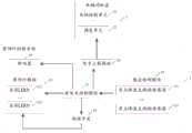
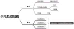
在一实例中,提供一种轨道车辆司机室多点阵激光测距反馈装饰灯控制系统,如图5所示,包括:供电及控制板、3个激光感应探头(感应检测模块)、装饰灯模组、信号记录上载模块和蜂鸣器。其中,信号记录上载模块与轨道车辆司机室中的LCU(车辆控制单元)和调度室(调度单元)连接。In one example, a multi-dot matrix laser ranging feedback decorative light control system for rail vehicle cabs is provided, as shown in Figure 5, including: power supply and control board, 3 laser induction probes (sensing detection modules), decorative light module, signal record upload module and buzzer. Wherein, the signal recording and uploading module is connected with the LCU (vehicle control unit) and the dispatching room (dispatching unit) in the cab of the rail vehicle.
其中,如图6所示,该系统安装在每列车的司机室操纵台上,通过3个多点阵测距传感器实时检测并判断驾驶人员是否就位,两侧是否有人员接近司机台,将数据上传至LCU记录并反馈至调度室。及时提醒驾驶人员及值班人员,并综合考虑以上因素,改变装饰灯具的点亮状态,使灯具可以在内置的几种模式之间进行柔和的切换。实现智能提醒和装饰的效果。Among them, as shown in Figure 6, the system is installed on the driver's cab console of each train. It detects and judges whether the driver is in place in real time through three multi-point matrix ranging sensors, and whether there are people approaching the driver's console on both sides. The data is uploaded to the LCU for recording and fed back to the dispatch room. Remind the driver and the on-duty personnel in time, and comprehensively consider the above factors, change the lighting status of the decorative lamps, so that the lamps can be softly switched among several built-in modes. Realize the effect of intelligent reminder and decoration.
进一步,3个多点阵测距传感器连接框图如图7所示。Further, the connection block diagram of three multi-dot matrix ranging sensors is shown in Figure 7.
通过该系统,可以实现通过检测司机室人员分布及驾驶人员在岗状态来实时改变灯具装饰显示效果,同时将数据上传至LCU记录并反馈至调度室。及时提醒驾驶人员及值班人员的功能。Through this system, it is possible to change the decorative display effect of lamps and lanterns in real time by detecting the distribution of cab personnel and the status of drivers on duty. At the same time, the data is uploaded to the LCU for recording and fed back to the dispatching room. The function of reminding the driver and the on-duty personnel in time.
本发明实施例还提供一种装饰灯控制方法,用于如本发明实施例所述的装饰灯控制系统1;如图8所示,该方法包括如下步骤:The embodiment of the present invention also provides a decorative light control method, which is used in the decorative
步骤201:基于所述装饰灯控制系统中的感应检测模块,经过绝对距离检测技术,得到与所述装饰灯控制系统对应的车辆司机室内的人员分布信息。Step 201: Based on the inductive detection module in the decorative light control system, obtain the personnel distribution information in the driver's compartment of the vehicle corresponding to the decorative light control system through absolute distance detection technology.
具体的实施过程参考对上述装饰灯控制系统1中感应检测模块12的检测原理的描述,此处不再赘述。For the specific implementation process, refer to the description of the detection principle of the
步骤202:所述感应检测模块发送所述人员分布信息至所述装饰灯控制系统中的供电及控制模块。Step 202: The induction detection module sends the personnel distribution information to the power supply and control module in the decorative light control system.
具体的实施过程参考对上述装饰灯控制系统1中感应检测模块12与供电及控制模块11的连接关系以及交互过程,此处不再赘述。For the specific implementation process, refer to the connection relationship and interaction process between the
步骤203:所述供电及控制模块根据所述人员分布信息发送第一控制信号至所述装饰灯控制系统中的装饰灯模组,完成对所述装饰灯模组中每个全彩LED灯的显示控制。Step 203: The power supply and control module sends a first control signal to the decorative light module in the decorative light control system according to the personnel distribution information, and completes the control of each full-color LED light in the decorative light module. Display controls.
具体的实施过程参考对上述装饰灯控制系统1中供电及控制模块11与装饰灯模组13的连接关系,以及供电及控制模块11对装饰灯模组13的控制过程,此处不再赘述。For the specific implementation process, refer to the connection relationship between the power supply and
本发明实施例提供的装饰灯控制方法,通过检测司机室人员分布情况来实时改变灯具装饰显示效果,因此,通过装饰灯的状态可以直观地反映出司机室人员分布状态,同时,全彩LED灯的灯光效果相较以往司机室的单调工业感更具有视觉上的观赏性,增加了驾驶人员的舒适性及感官性,增加了驾驶操纵人员的幸福感,使得司机室更加智能化和科技化;利用多点阵激光测距传感器,测距范围更广,抗干扰能力更强,可实现大范围的空间立体监测。因此,通过实施本发明,降低了装饰灯效果显示的局限性。The decorative lamp control method provided by the embodiment of the present invention changes the decorative display effect of lamps and lanterns in real time by detecting the distribution of personnel in the cab. Therefore, the status of the decorative lamp can directly reflect the distribution of personnel in the cab. Compared with the monotonous industrial feeling of the previous driver's cab, the lighting effect is more visually ornamental, which increases the comfort and sensory of the driver, increases the happiness of the driver and operator, and makes the driver's cab more intelligent and technological; Using the multi-dot matrix laser ranging sensor, the ranging range is wider, the anti-interference ability is stronger, and a large-scale spatial three-dimensional monitoring can be realized. Therefore, by implementing the present invention, the limitation of displaying the decorative light effect is reduced.
作为本发明实施例一种可选的实施方式,步骤202之后,所述方法还包括:所述供电及控制模块通过所述装饰灯控制系统中的信号上载模块将所述人员分布信息发送至所述车辆司机室内的车辆控制单元和调度单元,以及根据所述人员分布信息发送第二控制信号至所述装饰灯控制系统中的蜂鸣器,完成对所述蜂鸣器的控制。As an optional implementation manner of the embodiment of the present invention, after
具体的实施过程参考对上述装饰灯控制系统1中供电及控制模块11、信号上载模块、车辆控制单元21、调度单元22和蜂鸣器16之间的连接关系,以及供电及控制模块11对蜂鸣器16的控制过程,此处不再赘述。The specific implementation process refers to the connection relationship between the power supply and
本发明实施例还提供一种装饰灯控制装置,如图9所示,该装置包括:The embodiment of the present invention also provides a decorative light control device, as shown in Figure 9, the device includes:
检测模块301,用于基于所述装饰灯控制系统中的感应检测模块,经过绝对距离检测技术,得到与所述装饰灯控制系统对应的车辆司机室内的人员分布信息;详细内容参见上述方法实施例中步骤201的相关描述。The detection module 301 is used to obtain the personnel distribution information in the vehicle cab corresponding to the decorative light control system through the absolute distance detection technology based on the induction detection module in the decorative light control system; for details, refer to the above method embodiment The related description of
发送模块302,用于所述感应检测模块发送所述人员分布信息至所述装饰灯控制系统中的供电及控制模块;详细内容参见上述方法实施例中步骤202的相关描述。The sending module 302 is used for the induction detection module to send the personnel distribution information to the power supply and control module in the decorative light control system; for details, refer to the relevant description of
控制模块303,用于所述供电及控制模块根据所述人员分布信息发送第一控制信号至所述装饰灯控制系统中的装饰灯模组,完成对所述装饰灯模组中每个全彩LED灯的显示控制;详细内容参见上述方法实施例中步骤203的相关描述。The control module 303 is used for the power supply and control module to send a first control signal to the decorative light module in the decorative light control system according to the personnel distribution information, and complete the control of each full-color light module in the decorative light module. Display control of LED lights; for details, refer to the relevant description of
本发明实施例提供的装饰灯控制装置,通过检测司机室人员分布情况来实时改变灯具装饰显示效果,因此,通过装饰灯的状态可以直观地反映出司机室人员分布状态,同时,全彩LED灯的灯光效果相较以往司机室的单调工业感更具有视觉上的观赏性,增加了驾驶人员的舒适性及感官性,增加了驾驶操纵人员的幸福感,使得司机室更加智能化和科技化;利用多点阵激光测距传感器,测距范围更广,抗干扰能力更强,可实现大范围的空间立体监测。因此,通过实施本发明,降低了装饰灯效果显示的局限性。The decorative light control device provided by the embodiment of the present invention changes the decorative display effect of the lamps and lanterns in real time by detecting the distribution of personnel in the driver's cab. Compared with the monotonous industrial feeling of the previous driver's cab, the lighting effect is more visually ornamental, which increases the comfort and sensory of the driver, increases the happiness of the driver and operator, and makes the driver's cab more intelligent and technological; Using the multi-dot matrix laser ranging sensor, the ranging range is wider, the anti-interference ability is stronger, and a large-scale spatial three-dimensional monitoring can be realized. Therefore, by implementing the present invention, the limitation of displaying the decorative light effect is reduced.
作为本发明实施例一种可选的实施方式,所述装置还包括:所述供电及控制模块通过所述装饰灯控制系统中的信号上载模块将所述人员分布信息发送至所述车辆司机室内的车辆控制单元和调度单元,以及根据所述人员分布信息发送第二控制信号至所述装饰灯控制系统中的蜂鸣器,完成对所述蜂鸣器的控制。As an optional implementation of the embodiment of the present invention, the device further includes: the power supply and control module sends the personnel distribution information to the vehicle driver's compartment through the signal upload module in the decorative light control system The vehicle control unit and dispatching unit, and send a second control signal to the buzzer in the decorative light control system according to the personnel distribution information to complete the control of the buzzer.
本发明实施例提供的装饰灯控制装置的功能描述详细参见上述实施例中装饰灯控制方法描述。For a detailed description of the functions of the decorative light control device provided in the embodiment of the present invention, refer to the description of the decorative light control method in the foregoing embodiments.
本发明实施例还提供一种存储介质,如图10所示,其上存储有计算机程序401,该指令被处理器执行时实现上述实施例中装饰灯控制方法的步骤。其中,存储介质可为磁碟、光盘、只读存储记忆体(Read-Only Memory,ROM)、随机存储记忆体(Random AccessMemory,RAM)、快闪存储器(Flash Memory)、硬盘(Hard Disk Drive,HDD)或固态硬盘(Solid-State Drive,SSD)等;所述存储介质还可以包括上述种类的存储器的组合。The embodiment of the present invention also provides a storage medium, as shown in FIG. 10 , on which a
本领域技术人员可以理解,实现上述实施例方法中的全部或部分流程,是可以通过计算机程序来指令相关的硬件来完成,所述的程序可存储于一计算机可读取存储介质中,该程序在执行时,可包括如上述各方法的实施例的流程。其中,所述存储介质可为磁碟、光盘、只读存储记忆体(Read-Only Memory,ROM)、随机存储记忆体(Random AccessMemory,RAM)、快闪存储器(FlashMemory)、硬盘(Hard Disk Drive,HDD)或固态硬盘(Solid-State Drive,SSD)等;所述存储介质还可以包括上述种类的存储器的组合。Those skilled in the art can understand that all or part of the processes in the methods of the above-mentioned embodiments can be completed by instructing related hardware through computer programs, and the programs can be stored in a computer-readable storage medium. During execution, it may include the processes of the embodiments of the above-mentioned methods. Wherein, the storage medium can be a magnetic disk, an optical disk, a read-only memory (Read-Only Memory, ROM), a random access memory (Random AccessMemory, RAM), a flash memory (FlashMemory), a hard disk (Hard Disk Drive) , HDD) or solid-state hard disk (Solid-State Drive, SSD), etc.; the storage medium may also include a combination of the above-mentioned types of memory.
本发明实施例还提供了一种电子设备,如图11所示,该电子设备可以包括处理器51和存储器52,其中处理器51和存储器52可以通过总线或者其他方式连接,图11中以通过总线连接为例。The embodiment of the present invention also provides an electronic device. As shown in FIG. 11 , the electronic device may include a
处理器51可以为中央处理器(Central Processing Unit,CPU)。处理器51还可以为其他通用处理器、数字信号处理器(Digital Signal Processor,DSP)、专用集成电路(Application Specific Integrated Circuit,ASIC)、现场可编程门阵列(Field-Programmable Gate Array,FPGA)或者其他可编程逻辑器件、分立门或者晶体管逻辑器件、分立硬件组件等芯片,或者上述各类芯片的组合。The
存储器52作为一种非暂态计算机可读存储介质,可用于存储非暂态软件程序、非暂态计算机可执行程序以及模块,如本发明实施例中的对应的程序指令/模块。处理器51通过运行存储在存储器52中的非暂态软件程序、指令以及模块,从而执行处理器的各种功能应用以及数据处理,即实现上述方法实施例中的装饰灯控制方法。As a non-transitory computer-readable storage medium, the
存储器52可以包括存储程序区和存储数据区,其中,存储程序区可存储操作装置、至少一个功能所需要的应用程序;存储数据区可存储处理器51所创建的数据等。此外,存储器52可以包括高速随机存取存储器,还可以包括非暂态存储器,例如至少一个磁盘存储器件、闪存器件、或其他非暂态固态存储器件。在一些实施例中,存储器52可选包括相对于处理器51远程设置的存储器,这些远程存储器可以通过网络连接至处理器51。上述网络的实例包括但不限于互联网、企业内部网、局域网、移动通信网及其组合。The
所述一个或者多个模块存储在所述存储器52中,当被所述处理器51执行时,执行如图8所示实施例中的装饰灯控制方法。The one or more modules are stored in the
上述电子设备具体细节可以对应参阅图8所示的实施例中对应的相关描述和效果进行理解,此处不再赘述。Specific details of the foregoing electronic device may be understood by referring to corresponding descriptions and effects in the embodiment shown in FIG. 8 , and details are not repeated here.
虽然结合附图描述了本发明的实施例,但是本领域技术人员可以在不脱离本发明的精神和范围的情况下做出各种修改和变型,这样的修改和变型均落入由所附权利要求所限定的范围之内。Although the embodiments of the present invention have been described in conjunction with the accompanying drawings, those skilled in the art can make various modifications and variations without departing from the spirit and scope of the present invention. within the bounds of the requirements.
Claims (10)
Priority Applications (1)
| Application Number | Priority Date | Filing Date | Title |
|---|---|---|---|
| CN202310295106.8ACN116321624A (en) | 2023-03-23 | 2023-03-23 | A decorative lamp control system, method, device, storage medium and electronic equipment |
Applications Claiming Priority (1)
| Application Number | Priority Date | Filing Date | Title |
|---|---|---|---|
| CN202310295106.8ACN116321624A (en) | 2023-03-23 | 2023-03-23 | A decorative lamp control system, method, device, storage medium and electronic equipment |
Publications (1)
| Publication Number | Publication Date |
|---|---|
| CN116321624Atrue CN116321624A (en) | 2023-06-23 |
Family
ID=86818498
Family Applications (1)
| Application Number | Title | Priority Date | Filing Date |
|---|---|---|---|
| CN202310295106.8APendingCN116321624A (en) | 2023-03-23 | 2023-03-23 | A decorative lamp control system, method, device, storage medium and electronic equipment |
Country Status (1)
| Country | Link |
|---|---|
| CN (1) | CN116321624A (en) |
Citations (4)
| Publication number | Priority date | Publication date | Assignee | Title |
|---|---|---|---|---|
| JP2012240590A (en)* | 2011-05-23 | 2012-12-10 | Jvc Kenwood Corp | Vehicle lamp body control device |
| WO2022007983A2 (en)* | 2020-07-10 | 2022-01-13 | 华人运通(上海)云计算科技有限公司 | Method and apparatus for controlling vehicle light |
| CN114347932A (en)* | 2021-12-30 | 2022-04-15 | 宜宾凯翼汽车有限公司 | Vehicle personalized control system and method based on state of passenger in vehicle |
| CN114423121A (en)* | 2021-12-23 | 2022-04-29 | 中山市德马汽车零部件有限公司 | Vehicle intelligent perception light control method and system |
- 2023
- 2023-03-23CNCN202310295106.8Apatent/CN116321624A/enactivePending
Patent Citations (4)
| Publication number | Priority date | Publication date | Assignee | Title |
|---|---|---|---|---|
| JP2012240590A (en)* | 2011-05-23 | 2012-12-10 | Jvc Kenwood Corp | Vehicle lamp body control device |
| WO2022007983A2 (en)* | 2020-07-10 | 2022-01-13 | 华人运通(上海)云计算科技有限公司 | Method and apparatus for controlling vehicle light |
| CN114423121A (en)* | 2021-12-23 | 2022-04-29 | 中山市德马汽车零部件有限公司 | Vehicle intelligent perception light control method and system |
| CN114347932A (en)* | 2021-12-30 | 2022-04-15 | 宜宾凯翼汽车有限公司 | Vehicle personalized control system and method based on state of passenger in vehicle |
Similar Documents
| Publication | Publication Date | Title |
|---|---|---|
| CN102014560B (en) | Adaptive light emitting diode (LED) illumination device and control method thereof | |
| US9161420B2 (en) | System for controlling light in wireless manner | |
| CN106163020B (en) | Intelligent control method and system for automobile atmosphere lamp | |
| CN201937890U (en) | Self-adaptive light emitting diode (LED) illuminator | |
| CN102143213A (en) | Intelligent lighting control system based on Internet of Things architecture | |
| JP2023504401A (en) | Dynamically controlled micro LED pixel array | |
| CN103052209A (en) | Wireless synchronizing system for LED (Light Emitting Diode) illumination | |
| JP5877372B2 (en) | Lighting control apparatus and lighting system | |
| CN119497281A (en) | Intelligent control method, device, electronic device and storage medium for vehicle atmosphere light | |
| CN116321624A (en) | A decorative lamp control system, method, device, storage medium and electronic equipment | |
| JP2013004311A (en) | Lighting control system | |
| CN119497277A (en) | Editable, self-closed-loop dynamic OLED automobile taillight control system and method | |
| CN118810612A (en) | Intelligent interactive grille light system and interactive method based on multi-signal pattern recognition | |
| CN201967205U (en) | Intelligent lighting control system based on Internet of Things architecture | |
| CN118647109A (en) | Lighting and its control system | |
| CN111836444A (en) | Intelligent street lamp system and control method thereof | |
| CN116506999A (en) | Intelligent street lamp control method, system, intelligent street lamp and storage medium | |
| TWI542253B (en) | Wireless lighting control interface display method | |
| CN103096600B (en) | Acousto-optic control circuit | |
| CN110708831A (en) | Urban central lighting control method and system | |
| CN211481571U (en) | Three-dimensional visual light control system | |
| CN214256687U (en) | Lighting system | |
| CN211352562U (en) | Scene interaction energy-saving type illuminating lamp | |
| Durgun et al. | Cloud-based adjustable and section led pattern controlled street light | |
| CN114513888A (en) | Bus-based microwave sensor group control method, computer device, and computer-readable storage medium |
Legal Events
| Date | Code | Title | Description |
|---|---|---|---|
| PB01 | Publication | ||
| PB01 | Publication | ||
| SE01 | Entry into force of request for substantive examination | ||
| SE01 | Entry into force of request for substantive examination |