CN116316859A - Wind power generating set and its control method, device, and computer-readable storage medium - Google Patents
Wind power generating set and its control method, device, and computer-readable storage mediumDownload PDFInfo
- Publication number
- CN116316859A CN116316859ACN202310552920.3ACN202310552920ACN116316859ACN 116316859 ACN116316859 ACN 116316859ACN 202310552920 ACN202310552920 ACN 202310552920ACN 116316859 ACN116316859 ACN 116316859A
- Authority
- CN
- China
- Prior art keywords
- switch
- rotor
- generating set
- circuit
- stator
- Prior art date
- Legal status (The legal status is an assumption and is not a legal conclusion. Google has not performed a legal analysis and makes no representation as to the accuracy of the status listed.)
- Pending
Links
- 238000000034methodMethods0.000titleclaimsabstractdescription33
- 230000004044responseEffects0.000claimsdescription13
- 239000003990capacitorSubstances0.000claimsdescription4
- 239000011159matrix materialSubstances0.000claimsdescription4
- 238000010248power generationMethods0.000abstractdescription17
- 238000005265energy consumptionMethods0.000description12
- 238000010586diagramMethods0.000description8
- 238000004590computer programMethods0.000description7
- 230000008569processEffects0.000description5
- 238000006243chemical reactionMethods0.000description3
- 238000012986modificationMethods0.000description3
- 230000004048modificationEffects0.000description3
- 238000012545processingMethods0.000description3
- 230000005540biological transmissionEffects0.000description2
- 238000013500data storageMethods0.000description2
- 230000007423decreaseEffects0.000description2
- 238000013461designMethods0.000description2
- 230000006870functionEffects0.000description2
- 230000021715photosynthesis, light harvestingEffects0.000description2
- 238000003491arrayMethods0.000description1
- 230000008901benefitEffects0.000description1
- 238000009434installationMethods0.000description1
- 230000003993interactionEffects0.000description1
- 239000004973liquid crystal related substanceSubstances0.000description1
- 230000003287optical effectEffects0.000description1
- 230000009467reductionEffects0.000description1
- 230000035945sensitivityEffects0.000description1
- 239000007787solidSubstances0.000description1
- 230000003068static effectEffects0.000description1
- 239000000758substrateSubstances0.000description1
- 230000001360synchronised effectEffects0.000description1
- 238000012546transferMethods0.000description1
Images


Classifications
- H—ELECTRICITY
- H02—GENERATION; CONVERSION OR DISTRIBUTION OF ELECTRIC POWER
- H02J—CIRCUIT ARRANGEMENTS OR SYSTEMS FOR SUPPLYING OR DISTRIBUTING ELECTRIC POWER; SYSTEMS FOR STORING ELECTRIC ENERGY
- H02J3/00—Circuit arrangements for AC mains or AC distribution networks
- H02J3/38—Arrangements for parallely feeding a single network by two or more generators, converters or transformers
- H02J3/381—Dispersed generators
- F—MECHANICAL ENGINEERING; LIGHTING; HEATING; WEAPONS; BLASTING
- F03—MACHINES OR ENGINES FOR LIQUIDS; WIND, SPRING, OR WEIGHT MOTORS; PRODUCING MECHANICAL POWER OR A REACTIVE PROPULSIVE THRUST, NOT OTHERWISE PROVIDED FOR
- F03D—WIND MOTORS
- F03D7/00—Controlling wind motors
- F03D7/02—Controlling wind motors the wind motors having rotation axis substantially parallel to the air flow entering the rotor
- F03D7/028—Controlling wind motors the wind motors having rotation axis substantially parallel to the air flow entering the rotor controlling wind motor output power
- F—MECHANICAL ENGINEERING; LIGHTING; HEATING; WEAPONS; BLASTING
- F03—MACHINES OR ENGINES FOR LIQUIDS; WIND, SPRING, OR WEIGHT MOTORS; PRODUCING MECHANICAL POWER OR A REACTIVE PROPULSIVE THRUST, NOT OTHERWISE PROVIDED FOR
- F03D—WIND MOTORS
- F03D9/00—Adaptations of wind motors for special use; Combinations of wind motors with apparatus driven thereby; Wind motors specially adapted for installation in particular locations
- F03D9/20—Wind motors characterised by the driven apparatus
- F03D9/25—Wind motors characterised by the driven apparatus the apparatus being an electrical generator
- F03D9/255—Wind motors characterised by the driven apparatus the apparatus being an electrical generator connected to electrical distribution networks; Arrangements therefor
- F03D9/257—Wind motors characterised by the driven apparatus the apparatus being an electrical generator connected to electrical distribution networks; Arrangements therefor the wind motor being part of a wind farm
- H—ELECTRICITY
- H02—GENERATION; CONVERSION OR DISTRIBUTION OF ELECTRIC POWER
- H02P—CONTROL OR REGULATION OF ELECTRIC MOTORS, ELECTRIC GENERATORS OR DYNAMO-ELECTRIC CONVERTERS; CONTROLLING TRANSFORMERS, REACTORS OR CHOKE COILS
- H02P9/00—Arrangements for controlling electric generators for the purpose of obtaining a desired output
- H02P9/007—Control circuits for doubly fed generators
- H—ELECTRICITY
- H02—GENERATION; CONVERSION OR DISTRIBUTION OF ELECTRIC POWER
- H02P—CONTROL OR REGULATION OF ELECTRIC MOTORS, ELECTRIC GENERATORS OR DYNAMO-ELECTRIC CONVERTERS; CONTROLLING TRANSFORMERS, REACTORS OR CHOKE COILS
- H02P9/00—Arrangements for controlling electric generators for the purpose of obtaining a desired output
- H02P9/10—Control effected upon generator excitation circuit to reduce harmful effects of overloads or transients, e.g. sudden application of load, sudden removal of load, sudden change of load
- H02P9/102—Control effected upon generator excitation circuit to reduce harmful effects of overloads or transients, e.g. sudden application of load, sudden removal of load, sudden change of load for limiting effects of transients
- H—ELECTRICITY
- H02—GENERATION; CONVERSION OR DISTRIBUTION OF ELECTRIC POWER
- H02J—CIRCUIT ARRANGEMENTS OR SYSTEMS FOR SUPPLYING OR DISTRIBUTING ELECTRIC POWER; SYSTEMS FOR STORING ELECTRIC ENERGY
- H02J2300/00—Systems for supplying or distributing electric power characterised by decentralized, dispersed, or local generation
- H02J2300/20—The dispersed energy generation being of renewable origin
- H02J2300/28—The renewable source being wind energy
- H—ELECTRICITY
- H02—GENERATION; CONVERSION OR DISTRIBUTION OF ELECTRIC POWER
- H02P—CONTROL OR REGULATION OF ELECTRIC MOTORS, ELECTRIC GENERATORS OR DYNAMO-ELECTRIC CONVERTERS; CONTROLLING TRANSFORMERS, REACTORS OR CHOKE COILS
- H02P2101/00—Special adaptation of control arrangements for generators
- H02P2101/15—Special adaptation of control arrangements for generators for wind-driven turbines
- H—ELECTRICITY
- H02—GENERATION; CONVERSION OR DISTRIBUTION OF ELECTRIC POWER
- H02P—CONTROL OR REGULATION OF ELECTRIC MOTORS, ELECTRIC GENERATORS OR DYNAMO-ELECTRIC CONVERTERS; CONTROLLING TRANSFORMERS, REACTORS OR CHOKE COILS
- H02P2103/00—Controlling arrangements characterised by the type of generator
- H02P2103/10—Controlling arrangements characterised by the type of generator of the asynchronous type
- Y—GENERAL TAGGING OF NEW TECHNOLOGICAL DEVELOPMENTS; GENERAL TAGGING OF CROSS-SECTIONAL TECHNOLOGIES SPANNING OVER SEVERAL SECTIONS OF THE IPC; TECHNICAL SUBJECTS COVERED BY FORMER USPC CROSS-REFERENCE ART COLLECTIONS [XRACs] AND DIGESTS
- Y02—TECHNOLOGIES OR APPLICATIONS FOR MITIGATION OR ADAPTATION AGAINST CLIMATE CHANGE
- Y02E—REDUCTION OF GREENHOUSE GAS [GHG] EMISSIONS, RELATED TO ENERGY GENERATION, TRANSMISSION OR DISTRIBUTION
- Y02E10/00—Energy generation through renewable energy sources
- Y02E10/70—Wind energy
- Y02E10/76—Power conversion electric or electronic aspects
Landscapes
- Engineering & Computer Science (AREA)
- Power Engineering (AREA)
- Life Sciences & Earth Sciences (AREA)
- Sustainable Development (AREA)
- Sustainable Energy (AREA)
- Chemical & Material Sciences (AREA)
- Combustion & Propulsion (AREA)
- Mechanical Engineering (AREA)
- General Engineering & Computer Science (AREA)
- Control Of Eletrric Generators (AREA)
Abstract
Translated fromChinese
Description
Translated fromChinese技术领域technical field
本公开涉及风力发电领域,更具体地,涉及一种风力发电机组及其控制方法、装置、计算机可读存储介质。The present disclosure relates to the field of wind power generation, and more specifically, to a wind power generating set and its control method, device, and computer-readable storage medium.
背景技术Background technique
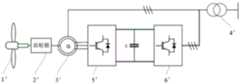
目前并网型风力发电机组存在两大主流技术路线,一种为直驱型风力发电机组,采用永磁同步发电机来转换电能,另一种为双馈型风力发电机组,采用异步发电机来转换电能,并且异步发电机的定子回路和转子回路都直接或间接地接入电网,实现双端馈电,即异步发电机具体为双馈异步发电机。传统的双馈型风力发电机组具体如图1所示,叶轮1'带动齿轮箱2',实现风能对机械能的转换;齿轮箱2'带动异步发电机3'并实现机械能对电能的转换;异步发电机3'的定子侧通过升压变压器4'升压并并入风电场内部馈线上;异步发电机3'的转子侧电能通过机侧变流器5'、网侧变流器6'和升压变压器4'分别进行换流和升压,最终汇入风电场内部馈线上。在图1中,无论是变流器的高压侧还是低压侧,工作频率均为50Hz;此外,升压变压器4'的高压侧一般都为35kV,低压侧电压等级根据机型不同而不同,一般选用690V占多数。鉴于此,图1所示的双馈型风力发电机组也可叫做低压工频型双馈异步风力发电机组。双馈型风力发电机组具有可以在不同的转速下实现恒频发电,满足用电负载和并网的要求的优势。At present, there are two mainstream technical routes for grid-connected wind turbines, one is direct-drive wind turbines, which use permanent magnet synchronous generators to convert electric energy, and the other is doubly-fed wind turbines, which use asynchronous generators to The electrical energy is converted, and the stator circuit and the rotor circuit of the asynchronous generator are directly or indirectly connected to the power grid to realize double-end feeding, that is, the asynchronous generator is specifically a double-fed asynchronous generator. The traditional doubly-fed wind turbine is specifically shown in Figure 1. The impeller 1' drives the gearbox 2' to realize the conversion of wind energy to mechanical energy; the gearbox 2' drives the asynchronous generator 3' to realize the conversion of mechanical energy to electrical energy; The stator side of the generator 3' is boosted through the step-up transformer 4' and incorporated into the internal feeder of the wind farm; the rotor side electric energy of the asynchronous generator 3' is passed through the machine-side converter 5', grid-side converter 6' and The step-up transformer 4' performs commutation and step-up respectively, and finally connects to the internal feeder of the wind farm. In Figure 1, both the high-voltage side and the low-voltage side of the converter operate at a frequency of 50 Hz; in addition, the high-voltage side of the step-up transformer 4' is generally 35kV, and the voltage level of the low-voltage side varies according to different models. 690V is used in the majority. In view of this, the doubly-fed wind turbine shown in Figure 1 can also be called a low-voltage power frequency doubly-fed asynchronous wind turbine. Doubly-fed wind turbines have the advantage of being able to achieve constant-frequency power generation at different speeds to meet the requirements of power loads and grid connection.
叶尖速比是风力发电机组的一个重要性能指标,指的是风轮叶片尖端线速度与风速之比,叶片越长,或者风轮转速越快,同风速下的叶尖速比就越大。为增大机组发电量,需要减小叶片设计叶尖速比。对于双馈型风力发电机组,在低风速时,要想使风轮运行于最佳的叶尖速比,需要风轮转速随风速降低而降低,这使得转差(异步发电机的定子旋转磁场转速与转子转速之差)过大,而由于转子电压与转差成正比,过大的转差会造成转子电压过高,超出机侧变流器的安全工作范围。因此,为保证机侧变流器安全,必须放弃风轮的最佳叶尖速比,即放弃最佳风功率捕获,导致双馈机组在轻载时发电效率远低于直驱机组。Tip speed ratio is an important performance index of wind turbines. It refers to the ratio of the linear speed of the tip of the wind rotor blade to the wind speed. The longer the blade, or the faster the speed of the wind rotor, the greater the tip speed ratio at the same wind speed. . In order to increase the generating capacity of the unit, it is necessary to reduce the design tip speed ratio of the blade. For doubly-fed wind turbines, at low wind speeds, in order to make the wind rotor run at the best tip speed ratio, the speed of the wind rotor needs to decrease as the wind speed decreases, which makes the slip (the stator rotation of the asynchronous generator The difference between the magnetic field speed and the rotor speed) is too large, and because the rotor voltage is proportional to the slip, too large slip will cause the rotor voltage to be too high, which exceeds the safe working range of the machine-side converter. Therefore, in order to ensure the safety of the machine-side converter, the optimal tip speed ratio of the wind rotor must be abandoned, that is, the optimal wind power capture must be abandoned, resulting in the power generation efficiency of the doubly-fed unit being much lower than that of the direct-drive unit at light loads.
发明内容Contents of the invention
因此,如何提升双馈型风力发电机组在轻载时的发电效率,至关重要。Therefore, how to improve the power generation efficiency of the doubly-fed wind turbine at light load is very important.
在一个总的方面,提供一种风力发电机组,所述风力发电机组包括:发电机;转子回路,连接在所述发电机的转子和并网点之间;短路开关,连接在所述发电机的转子与短路点之间;定子回路,连接在所述发电机的定子和所述并网点之间,所述定子回路包括全功率变流器、定子开关和旁路开关,其中,所述全功率变流器和所述定子开关串联连接之后与所述旁路开关并联连接。In a general aspect, a wind power generating set is provided, the wind power generating set includes: a generator; a rotor circuit connected between the rotor of the generator and a grid connection point; a short-circuit switch connected to the generator Between the rotor and the short-circuit point; the stator circuit, connected between the stator of the generator and the grid-connected point, the stator circuit includes a full-power converter, a stator switch and a bypass switch, wherein the full-power The converter and the stator switch are connected in series and then connected in parallel with the bypass switch.
可选地,所述发电机的定子输出电压与所述风力发电机组所并入的电网的电压相匹配;所述风力发电机组还包括设置在所述转子回路中的升压变压器。Optionally, the output voltage of the stator of the generator matches the voltage of the grid into which the wind generating set is integrated; the wind generating set further includes a step-up transformer arranged in the rotor circuit.
可选地,所述升压变压器的容量的取值范围为所述风力发电机组的容量的20%至35%。Optionally, the value range of the capacity of the step-up transformer is 20% to 35% of the capacity of the wind power generating set.
可选地,所述全功率变流器包括以下至少一种:模块化多电平变流器、模块化多电平矩阵变流器。Optionally, the full power converter includes at least one of the following: a modular multilevel converter and a modular multilevel matrix converter.
可选地,所述全功率变流器的子模块包括以下至少一种:半桥子模块、全桥子模块、钳位双子模块、五开关子模块、四电容组合的半桥子模块。Optionally, the sub-module of the full power converter includes at least one of the following: a half-bridge sub-module, a full-bridge sub-module, a clamping twin sub-module, a five-switch sub-module, and a half-bridge sub-module combined with four capacitors.
可选地,所述转子回路包括依次串联连接的转子机侧开关、转子变流器和转子网侧开关,所述转子机侧开关的一端连接在所述发电机的转子和所述短路开关之间,所述转子机侧开关的另一端连接所述转子变流器。Optionally, the rotor circuit includes a rotor machine-side switch, a rotor converter, and a rotor grid-side switch sequentially connected in series, and one end of the rotor machine-side switch is connected between the rotor of the generator and the short-circuit switch , the other end of the rotor machine-side switch is connected to the rotor converter.
可选地,所述风力发电机组还包括并网开关,所述并网开关的一端同时连接到所述转子回路的网侧端和所述定子回路的网侧端,所述并网开关的另一端连接到所述并网点。Optionally, the wind power generating set further includes a grid-connected switch, one end of the grid-connected switch is connected to the grid-side end of the rotor circuit and the grid-side end of the stator circuit at the same time, and the other end of the grid-connected switch One end is connected to the grid connection point.
在另一个总的方面,提供一种风力发电机组的控制方法,所述风力发电机组为上述任一风力发电机组,所述控制方法包括:获取所述风力发电机组的输出功率;响应于确定所述输出功率小于或等于预设功率,控制所述短路开关和所述定子开关闭合,并控制所述旁路开关断开;响应于确定所述输出功率大于所述预设功率,控制所述短路开关和所述定子开关断开,并控制所述旁路开关闭合。In another general aspect, there is provided a control method for a wind power generating set, the wind power generating set being any one of the above-mentioned wind power generating sets, the control method comprising: obtaining the output power of the wind power generating set; in response to determining the The output power is less than or equal to the preset power, control the short circuit switch and the stator switch to close, and control the bypass switch to open; in response to determining that the output power is greater than the preset power, control the short circuit The switch and the stator switch are disconnected, and the bypass switch is controlled to be closed.
可选地,所述预设功率等于所述风力发电机组的额定功率与预设占比的乘积,所述预设占比的取值范围为15%至30%。Optionally, the preset power is equal to the product of the rated power of the wind generating set and a preset ratio, and the preset ratio ranges from 15% to 30%.
在另一个总的方面,提供一种风力发电机组的控制装置,所述风力发电机组为上述任一风力发电机组,所述控制装置包括:获取单元,被配置为获取所述风力发电机组的输出功率;控制单元,被配置为响应于确定所述输出功率小于或等于预设功率,控制所述短路开关和所述定子开关闭合,并控制所述旁路开关断开;所述控制单元还被配置为响应于确定所述输出功率大于所述预设功率,控制所述短路开关和所述定子开关断开,并控制所述旁路开关闭合。In another general aspect, there is provided a control device for a wind power generating set, the wind power generating set is any one of the above-mentioned wind power generating sets, the control device includes: an acquisition unit configured to acquire the output of the wind power generating set power; a control unit configured to, in response to determining that the output power is less than or equal to a preset power, control the short-circuit switch and the stator switch to close, and control the bypass switch to open; the control unit is also It is configured to control the short-circuit switch and the stator switch to open, and control the bypass switch to close in response to determining that the output power is greater than the preset power.
可选地,所述预设功率等于所述风力发电机组的额定功率与预设占比的乘积,所述预设占比的取值范围为15%至30%。Optionally, the preset power is equal to the product of the rated power of the wind generating set and a preset ratio, and the preset ratio ranges from 15% to 30%.
在另一总的方面,提供一种计算机可读存储介质,当所述计算机可读存储介质中的指令被至少一个处理器运行时,促使所述至少一个处理器执行如上所述的风力发电机组的控制方法。In another general aspect, there is provided a computer-readable storage medium that, when executed by instructions in the computer-readable storage medium, causes at least one processor to execute a wind turbine as described above control method.
在另一总的方面,提供一种计算机设备,包括:至少一个处理器;至少一个存储计算机可执行指令的存储器,其中,所述计算机可执行指令在被所述至少一个处理器运行时,促使所述至少一个处理器执行如上所述的风力发电机组的控制方法。In another general aspect, there is provided a computer device comprising: at least one processor; at least one memory storing computer-executable instructions, wherein the computer-executable instructions, when executed by the at least one processor, cause The at least one processor executes the control method of the wind power plant as described above.
本公开提出了一种风力发电机组及其控制方法、装置、计算机可读存储介质,通过设置短路开关、旁路开关和全功率变流器,能够在低风速时通过闭合短路开关和定子开关、断开旁路开关(实践中还会断开转子回路上的开关),令转子回路退出并网,单独将带有全功率变流器的定子回路经并网点接入电网,可令发电机不作为双馈异步发电机运行,而转变为普通的异步发电机运行(即仅定子侧单端馈电),并利用全功率变流器实现定子侧电路的换流(转子回路接入时可利用转子回路上的转子变流器调节转子侧电流,进而实现定子侧电路的换流)。此时由于转子回路退出,全功率变流器又不受转差影响,所以可以降低叶轮转速来实现最佳叶尖速比,从而提高风功率捕获,提升双馈机组在轻载时的发电效率。该方案可降低风力发电机组的切入转速,提高双馈机组的变速范围,从而综合提高发电量。The disclosure proposes a wind power generating set and its control method, device, and computer-readable storage medium. By setting a short-circuit switch, a bypass switch, and a full-power converter, the short-circuit switch, the stator switch, and the stator switch can be closed at low wind speeds. Turn off the bypass switch (in practice, the switch on the rotor circuit will also be disconnected), so that the rotor circuit will withdraw from the grid connection, and the stator circuit with the full power converter will be connected to the grid through the grid connection point alone, so that the generator will not It operates as a doubly-fed asynchronous generator, but it is transformed into an ordinary asynchronous generator (that is, only the stator side is fed by a single end), and the full power converter is used to realize the commutation of the stator side circuit (it can be used when the rotor circuit is connected) The rotor converter on the rotor circuit adjusts the current on the rotor side, and then realizes the commutation of the stator side circuit). At this time, since the rotor circuit exits and the full power converter is not affected by slip, the impeller speed can be reduced to achieve the best tip speed ratio, thereby improving wind power capture and improving the power generation efficiency of the double-fed unit at light load . This solution can reduce the cut-in speed of the wind power generating set, increase the variable speed range of the doubly-fed generating set, and thus comprehensively increase the power generation.
应当理解的是,以上的一般描述和后文的细节描述仅是示例性和解释性的,并不能限制本公开。It is to be understood that both the foregoing general description and the following detailed description are exemplary and explanatory only and are not restrictive of the present disclosure.
附图说明Description of drawings
通过下面结合附图对实施例进行的描述,本公开的上述以及其他目的和特点将会变得更加清楚,在附图中:The above and other objects and features of the present disclosure will become more clear through the following description of the embodiments in conjunction with the accompanying drawings, in which:
图1是示出相关技术中的双馈异步风力发电机组的拓扑图;Fig. 1 is a topological diagram showing a doubly-fed asynchronous wind power generating set in the related art;
图2是示出根据本公开的一个实施例的风力发电机组的拓扑图;Fig. 2 is a topological diagram illustrating a wind power plant according to an embodiment of the present disclosure;
图3是示出根据本公开的另一个实施例的风力发电机组的拓扑图;Fig. 3 is a topological diagram showing a wind turbine according to another embodiment of the present disclosure;
图4至图8是示出根据本公开的实施例的全功率变流器的子模块拓扑图;4 to 8 are sub-module topology diagrams illustrating full power converters according to embodiments of the present disclosure;
图9是示出根据本公开的实施例的风力发电机组的控制方法的流程图;Fig. 9 is a flowchart illustrating a control method of a wind power generating set according to an embodiment of the present disclosure;
图10是示出根据本公开的实施例的风力发电机组的控制装置的框图;Fig. 10 is a block diagram showing a control device of a wind power generating set according to an embodiment of the present disclosure;
图11是示出根据本公开的实施例的计算机设备的框图。FIG. 11 is a block diagram illustrating a computer device according to an embodiment of the present disclosure.
图1附图标号说明:Explanation of the reference numerals in Figure 1:
1':叶轮;2':齿轮箱;3':异步发电机;4':升压变压器;5':机侧变流器;6':网侧变流器;1': impeller; 2': gearbox; 3': asynchronous generator; 4': step-up transformer; 5': machine-side converter; 6': grid-side converter;
图2和图3附图标号说明:Description of Figure 2 and Figure 3 reference numerals:
10:发电机;10: Generator;
20:转子回路;21:转子机侧开关;22:转子变流器;221:转子机侧变流器;222:转子网侧变流器;23:转子网侧开关;20: rotor circuit; 21: rotor machine side switch; 22: rotor converter; 221: rotor machine side converter; 222: rotor grid side converter; 23: rotor grid side switch;
30:短路开关;30: short circuit switch;
40:定子回路;41:全功率变流器;411:机侧变流器;412:网侧变流器;413:耗能电路;4131:耗能电阻;4132:耗能开关;42:定子开关;43:旁路开关;44:充电电路;441:充电电阻;442:充电开关;40: stator circuit; 41: full-power converter; 411: machine-side converter; 412: grid-side converter; 413: energy-dissipating circuit; 4131: energy-dissipating resistor; 4132: energy-dissipating switch; 42: stator switch; 43: bypass switch; 44: charging circuit; 441: charging resistor; 442: charging switch;
50:齿轮箱;50: gear box;
60:叶轮;60: impeller;
70:升压变压器;70: step-up transformer;
80:并网开关;80: Grid-connected switch;
A:并网点;A: grid connection point;
B:短路点。B: Short circuit point.
具体实施方式Detailed ways
提供下面的具体实施方式以帮助读者获得对在此描述的方法、设备和/或系统的全面理解。然而,在理解本申请的公开之后,在此描述的方法、设备和/或系统的各种改变、修改和等同物将是清楚的。例如,在此描述的操作的顺序仅是示例,并且不限于在此阐述的那些顺序,而是除了必须以特定的顺序发生的操作之外,可如在理解本申请的公开之后将是清楚的那样被改变。此外,为了更加清楚和简明,本领域已知的特征的描述可被省略。The following detailed description is provided to assist the reader in gaining an overall understanding of the methods, devices and/or systems described herein. However, various changes, modifications and equivalents of the methods, apparatus and/or systems described herein will be apparent after understanding the disclosure of the present application. For example, the order of operations described herein are examples only, and are not limited to those orders set forth herein, but, except for operations that must occur in a particular order, may occur as will become apparent after understanding the disclosure of this application. That's changed. Also, descriptions of features that are known in the art may be omitted for increased clarity and conciseness.
在此描述的特征可以以不同的形式来实现,而不应被解释为限于在此描述的示例。相反,已提供在此描述的示例,以仅示出实现在此描述的方法、设备和/或系统的许多可行方式中的一些可行方式,所述许多可行方式在理解本申请的公开之后将是清楚的。The features described herein may be implemented in different forms and should not be construed as limited to the examples described herein. Rather, the examples described herein have been provided to illustrate but a few of the many possible ways of implementing the methods, apparatus and/or systems described herein that would be useful after understanding the disclosure of the present application. clearly.
如在此使用的,术语“和/或”包括相关联的所列项中的任何一个以及任何两个或更多个的任何组合。As used herein, the term "and/or" includes any one and any combination of any two or more of the associated listed items.
尽管在此可使用诸如“第一”、“第二”和“第三”的术语来描述各种构件、组件、区域、层或部分,但是这些构件、组件、区域、层或部分不应被这些术语所限制。相反,这些术语仅用于将一个构件、组件、区域、层或部分与另一构件、组件、区域、层或部分进行区分。因此,在不脱离示例的教导的情况下,在此描述的示例中所称的第一构件、第一组件、第一区域、第一层或第一部分也可被称为第二构件、第二组件、第二区域、第二层或第二部分。Although terms such as "first", "second" and "third" may be used herein to describe various members, components, regions, layers or sections, these members, components, regions, layers or sections should not be referred to as These terms are limited. On the contrary, these terms are only used to distinguish one element, component, region, layer or section from another element, component, region, layer or section. Thus, a first member, a first component, a first region, a first layer, or a first portion referred to in examples described herein could also be termed a second member, a second component, or a first portion without departing from the teachings of the examples. Component, second area, second layer or second part.
在说明书中,当元件(诸如,层、区域或基底)被描述为“在”另一元件上、“连接到”或“结合到”另一元件时,该元件可直接“在”另一元件上、直接“连接到”或“结合到”另一元件,或者可存在介于其间的一个或多个其他元件。相反,当元件被描述为“直接在”另一元件上、“直接连接到”或“直接结合到”另一元件时,可不存在介于其间的其他元件。In the specification, when an element (such as a layer, region, or substrate) is described as being "on," "connected to," or "bonded to" another element, that element may be directly "on" another element. directly on, "connected to" or "coupled to" another element, or one or more other elements may be present therebetween. In contrast, when an element is described as being "directly on," "directly connected to" or "directly coupled to" another element, there may be no intervening elements present.
在此使用的术语仅用于描述各种示例,并不将用于限制公开。除非上下文另外清楚地指示,否则单数形式也意在包括复数形式。术语“包含”、“包括”和“具有”说明存在叙述的特征、数量、操作、构件、元件和/或它们的组合,但不排除存在或添加一个或多个其他特征、数量、操作、构件、元件和/或它们的组合。The terms used herein are for describing various examples only and will not be used to limit the disclosure. Singular forms are also intended to include plural forms unless the context clearly dictates otherwise. The terms "comprising", "including" and "having" indicate the presence of stated features, quantities, operations, components, elements and/or combinations thereof, but do not exclude the presence or addition of one or more other features, quantities, operations, components , components and/or combinations thereof.
除非另有定义,否则在此使用的所有术语(包括技术术语和科学术语)具有与由本公开所属领域的普通技术人员在理解本公开之后通常理解的含义相同的含义。除非在此明确地如此定义,否则术语(诸如,在通用词典中定义的术语)应被解释为具有与它们在相关领域的上下文和本公开中的含义一致的含义,并且不应被理想化或过于形式化地解释。Unless otherwise defined, all terms (including technical terms and scientific terms) used herein have the same meaning as commonly understood by one of ordinary skill in the art to which this disclosure belongs after understanding the present disclosure. Unless expressly so defined herein, terms (such as those defined in commonly used dictionaries) should be interpreted to have meanings consistent with their meanings in the context of the relevant art and in this disclosure, and should not be idealized or explained too formally.
此外,在示例的描述中,当认为公知的相关结构或功能的详细描述将引起对本公开的模糊解释时,将省略这样的详细描述。Also, in the description of examples, when it is considered that a detailed description of a well-known related structure or function will cause obscure interpretation of the present disclosure, such detailed description will be omitted.
下面将结合图2至图4介绍本公开的实施例提供的风力发电机组。The wind power generating set provided by the embodiments of the present disclosure will be described below with reference to FIG. 2 to FIG. 4 .
如图2所示,本公开一方面的实施例提供了一种风力发电机组,包括发电机10、转子回路20、短路开关30、定子回路40。As shown in FIG. 2 , an embodiment of one aspect of the present disclosure provides a wind power generating set, including a
发电机10具体为异步发电机。和现有的机组一样,发电机10之前还依次连接有齿轮箱50和叶轮60。The
转子回路20连接在发电机10的转子和并网点A之间,并网点A可直接连接电网,也可连接风电场内部馈线。转子回路20包括依次串联连接的转子机侧开关21、转子变流器22和转子网侧开关23,转子变流器22能够实现转子侧电路的换流,补偿机械频率和电频率之差,有效管理发电机10的运行状态。如图3所示,转子变流器22可采用传统的双馈变流器,具体包括转子机侧变流器221和转子网侧变流器222两部分,二者彼此独立控制,转子机侧变流器221可通过控制转子电流分量控制有功功率和无功功率,转子网侧变流器222可控制直流母线电压并确保转子变流器22运行在统一功率因数。通过在转子机侧变流器221和发电机10的转子之间设置转子机侧开关21,在转子网侧变流器222远离转子机侧变流器221的一侧设置转子网侧开关23,能够实现转子机侧变流器221和转子网侧变流器222的独立开关控制,保障了转子变流器22的可靠运行。The
短路开关30连接在发电机10的转子与短路点B之间,短路开关30连接发电机10的转子的一端具体是连接在发电机10的转子和转子回路20的转子机侧开关21之间,使得转子机侧开关21的一端连接在发电机10的转子和短路开关30之间,另一端连接转子变流器22。当短路开关30闭合,可令转子回路20因短接而退出并网。The short-
定子回路40连接在发电机10的定子和并网点A之间,定子回路40包括全功率变流器41、定子开关42和旁路开关43,其中,全功率变流器41和定子开关42串联连接之后与旁路开关43并联连接。通过在现有定子回路的基础上增设旁路开关43和全功率变流器41,能够与短路开关30相配合,在低风速时通过闭合短路开关30和定子开关42、断开旁路开关43(实践中还会断开转子回路20上的转子机侧开关21和转子网侧开关23),令转子回路20退出并网,单独将带有全功率变流器41的定子回路40经并网点A接入电网,可令发电机10不作为双馈异步发电机运行,而转变为普通的异步发电机运行(即仅定子侧单端馈电),并利用全功率变流器41的全功率运行实现定子侧电路的换流(转子回路20接入时可利用转子变流器22调节转子侧电流,进而实现定子侧电路的换流)。此时由于转子回路20退出,全功率变流器41又不受转差影响,所以可以降低叶轮60转速来实现最佳叶尖速比,从而提高风功率捕获,提升双馈机组在轻载时的发电效率。该方案可降低风力发电机组的切入转速,提高双馈机组的变速范围,从而综合提高发电量。The
可选地,与现有双馈机组的定子输出电压通常为690V或1140V不同的是,本公开的发电机10的定子输出电压与风力发电机组所并入的电网的电压相匹配,例如在电网电压为35kV时,定子输出电压也为35kV,在电网电压为10kV时,定子输出电压也为10kV,使得发电机10的定子直接输出中压,此时定子回路40不必连接升压变压器70,可减少一次电能转换环节,有助于进一步提升发电效率。同时,风力发电机组的升压变压器70设置在转子回路20中,可将690V、1140V等电压等级升压至35kV或10kV中压,由于仅用于为转子侧升压,因而能够大幅降低升压变压器70的容量和体积,节约了安装空间,并可降低升压变压器70布局位置的承重代价,进而带来对应的成本降低,提升了整机经济性。作为示例,对于将升压变压器70布局在机组机舱的情况,可降低机舱承重代价,对于将升压变压器70布局在塔底的情况,可降低塔底塔架的承重代价。Optionally, unlike the stator output voltage of the existing doubly-fed generator set, which is usually 690V or 1140V, the stator output voltage of the
进一步地,在发电机10的定子直接输出中压、升压变压器70设置在转子回路20中的情况下,升压变压器70的容量的取值范围为风力发电机组的容量的20%至35%。由于转子输出的功率通常约占总功率的20%至25%,所以升压变压器70的容量可相对于现有结构降低至少70%。此外,为保障使用安全,现有的升压变压器的容量往往在风力发电机组的容量的基础上保留有部分冗余,例如对于容量为6MW的风力发电机组,常采用容量为7MW的升压变压器,因此,升压变压器70的容量可略高于风力发电机组的容量的20%至25%。通过将升压变压器70的容量具体配置为风力发电机组的容量的20%至35%,既可满足转子侧的升压需求,保障机组的可靠运行,又能够大幅降低升压变压器70的容量和体积,提升整机经济性。具体地,可根据转子输出功率在风力发电机组容量中的实际占比来配置升压变压器70的容量取值。Further, when the stator of the
可选地,全功率变流器41包括以下至少一种:模块化多电平变流器(ModularMultilevel Converter,简称MMC)、模块化多电平矩阵变流器(Modular MultilevelMatrix Converter,简称M3C)。通过选用模块化多电平变流器或模块化多电平矩阵变流器,能够令定子侧直接输出中压,满足定子输出电压的取值需求,并且此时电压高、电流应力小、损耗小,有助于充分提升发电效率。应理解,对于发电机10的定子输出低压的实施例,全功率变流器41可为常规的输出低压的变流器,此时升压变压器70的设置位置可参考现有结构,即参考图1,同时连接定子回路40的网侧端和转子回路20的网侧端。Optionally, the
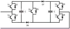
进一步地,如图3所示,全功率变流器41包括串联连接的机侧变流器411和网侧变流器412,机侧变流器411用于将交流电能转为直流电能,网侧变流器412用于将直流电能转为交流电能后,将发电机10产生的电能输送至并网点A。作为示例,如图3所示,机侧变流器411和网侧变流器412都采用模块化多电平变流器,采用三相结构,每相有上下两个桥臂,每个桥臂由N个子模块(Sub Module,简称SM)和一个桥臂电抗器Larm串联而成。Further, as shown in FIG. 3, the
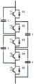
可选地,全功率变流器41的子模块包括以下至少一种:半桥子模块(参照图4)、全桥子模块(参照图5)、钳位双子模块(参照图6)、五开关子模块(参照图7)、四电容组合的半桥子模块(参照图8)。通过为全功率变流器41的子模块配置多种拓扑,能够根据具体应用场景的需求,综合考虑器件经济性、体积和控制复杂度选取合适的子模块拓扑,既提升了设计的灵活性,又有助于提升机组的发电效率。其中,除半桥子模块外,其他子模块均能够实现故障自清除。Optionally, the submodules of the
进一步地,全功率变流器41还包括耦合在机侧变流器411和网侧变流器412之间的耗能电路413,耗能电路413包括串联连接的耗能电阻4131和耗能开关4132。通过配置耗能电路413,能够在发电机10产生的电能不能传递至并网点A时通过耗能电阻4131的发热来消耗电能,以免损坏机侧变流器411和网侧变流器412。具体地,若网侧变流器412故障,电能可经机侧变流器411传递至耗能电阻4131;若机侧变流器411故障,机侧变流器411内的续流二极管可以把能量传递至耗能电阻4131来消耗。因此,应理解,为满足消耗电能的需求,耗能电阻4131的容量或电流要大,对电阻则无要求。Further, the
可选地,定子回路40还包括充电电路44,充电电路44与定子开关42并联连接,也就是全功率变流器41与并联连接的定子开关42以及充电电路44串联连接之后,与旁路开关43并联连接,充电电路44包括串联连接的充电电阻441和充电开关442。通过在定子开关42上并联连接充电电路44,能够令二者相互配合,并在启动状态下通过闭合充电开关442、断开定子开关42,令充电电阻441接入定子回路40中,从而在机组启动时拉低定子回路40上的电流,为全功率变流器41柔和地提供初始电压,降低全功率变流器41直接连接并网点A时产生冲击电流、损坏全功率变流器41内部元器件的风险。待充电完成后,可通过断开充电开关442、闭合定子开关42,令充电电阻441退出定子回路40,全功率变流器41进入正常工作状态。此外,通过将充电开关442也和充电电阻441一起与定子开关42并联,而不将充电电阻441与定子开关42并联连接之后与充电开关442串联连接,能够令充电开关442仅用于控制充电电路44的通断,而充电过程中通过充电开关442的电流较小,充电完成后充电开关442断开,定子回路40上的大电流也不会通过充电开关442,所以充电开关442可以选用小容量开关,有助于降低硬件成本。定子开关42则需要选用大容量开关,以保障定子回路40开关功能的可靠实现。实践中,判断充电是否完成可通过检测全功率变流器41所充得的电压是否足够来实现,确定充电完成后,可断开充电开关442,充电流程至此完成,可响应于充电流程完成,闭合定子开关42,使得控制流程简约高效。应理解,为满足缓冲需求,充电电阻441需要有较高的电阻,对容量则无要求。作为示例,与转子变流器22设置有转子机侧开关21和转子网侧开关23一样,全功率变流器41也可设置定子机侧开关和定子网侧开关,定子机侧开关设置在全功率变流器41的机侧变流器411和发电机10的定子之间,定子网侧开关设置在全功率变流器41的网侧变流器412远离机侧变流器411的一侧,本公开前文介绍的定子开关42可以是定子机侧开关,也可以是定子网侧开关(如图3所示)。Optionally, the
可选地,风力发电机组还包括并网开关80,并网开关80的一端同时连接到转子回路20的网侧端和定子回路40的网侧端,并网开关80的另一端连接到并网点A。通过在并网点A的前端设置并网开关80,能够为机组提供接入并网点A的总开关,充分保障对机组的全面控制,保障了使用安全。Optionally, the wind power generating set further includes a grid-connected
图9是示出根据本公开的实施例的风力发电机组的控制方法的流程图。应理解,受控制的风力发电机组为上述任一实施例的风力发电机组。根据本公开的实施例的风力发电机组的控制方法可由风力发电机组的单机控制器执行,也可以由风电场的场级控制器执行,并且由场级控制器执行时需要针对每台风力发电机组的实际运行情况单独予以控制。Fig. 9 is a flowchart illustrating a control method of a wind power generating set according to an embodiment of the present disclosure. It should be understood that the controlled wind power generating set is the wind power generating set in any of the above embodiments. The method for controlling a wind power generating set according to an embodiment of the present disclosure may be executed by a stand-alone controller of a wind generating set, or may be executed by a field-level controller of a wind farm. The actual operation of the system is controlled separately.
参照图9,在步骤S901中,获取风力发电机组的输出功率。需说明的是,根据本公开的实施例的风力发电机组的控制方法可以持续执行,例如可按照一定的频率定期获取实时的输出功率,再基于获取的输出功率执行后续的步骤,周而复始,实现风力发电机组的动态持续控制。Referring to Fig. 9, in step S901, the output power of the wind power generating set is acquired. It should be noted that the control method of the wind power generating set according to the embodiment of the present disclosure can be continuously executed, for example, the real-time output power can be obtained regularly according to a certain frequency, and then follow-up steps can be performed based on the obtained output power, and the cycle can be repeated to realize wind power generation. Dynamic continuous control of generator sets.
在步骤S902,响应于确定输出功率小于或等于预设功率,控制短路开关和定子开关闭合,并控制旁路开关断开。实践中,还会控制转子回路20上的转子机侧开关21和转子网侧开关23断开,以令转子回路20退出并网,并控制并网开关80闭合。此时发电机10作为普通的异步发电机运行(即定子侧单端馈电),并且定子回路40上的全功率变流器41参与并网,全功率变流器41将定子产生的电能输送至并网点A。由于参与并网的变流器为全功率变流器41,所以可将机组当前的运行模式称为全功率模式。In step S902, in response to determining that the output power is less than or equal to the preset power, the short-circuit switch and the stator switch are controlled to be closed, and the bypass switch is controlled to be opened. In practice, the rotor machine-
在步骤S903,响应于确定输出功率大于预设功率,控制短路开关和定子开关断开,并控制旁路开关闭合。与步骤S902同理,实践中,还会控制转子回路20上的转子机侧开关21和转子网侧开关23闭合,以令转子回路20参与并网,并网开关80则保持闭合状态不变。此时发电机10作为双馈异步发电机运行(即定子侧和转子侧双端馈电),并且定子回路40上的全功率变流器41退出运行,定子产生的电能直接输送至并网点A,转子回路20上的转子变流器22(采用传统的双馈变流器)参与并网,转子产生的电能通过转子变流器22和升压变压器70输送至并网点A。由于参与并网的变流器为双馈变流器(即转子变流器22),所以机组当前的运行模式为常规的双馈模式。应理解,此时定子产生的电能未经升压变压器70,直接输送至并网点A,实践中可利用转子机侧变流器221调整转子电压,进而将定子输出电压调整至中压(例如前述的35kV或10kV),从而令定子回路40无需连接升压变压器70,对于转子侧,由于转子机侧变流器221仅影响转子的机侧电压,所以转子的网侧电压仍为低压(例如前述的690V或1140V),不会影响升压变压器70的工作。In step S903, in response to determining that the output power is greater than the preset power, the short-circuit switch and the stator switch are controlled to be opened, and the bypass switch is controlled to be closed. Similar to step S902, in practice, the rotor machine-
根据本公开的实施例的风力发电机组的控制方法,通过配置预设功率,并根据输出功率与预设功率的大小关系来控制机组在全功率模式和双馈模式之间切换,能够为不同运行模式的切换提供准确的依据,保障了控制的可靠性。此外,本公开针对双馈机组在轻载时(即低风速时)发电效率不足的问题,出发点是在低风速时运行全功率模式,在高风速时运行常规的双馈模式,但不同的机组对风速的敏感程度不同,同样的风速对一个机组而言属于低风速,对另一个机组则可能属于高风速。对此,本公开通过将功率作为区分高低风速的依据参数,能够有效区分机组是处于轻载状态还是处于重载状态,进一步提升了控制的准确性。应理解,在风力发电机组处于启动状态时,尚无功率输出,发电机10将作为普通的异步发电机,但对于定子回路40还包括前述的充电电路44的实施例,此时需控制定子开关42断开,并控制充电开关442闭合,使全功率变流器41能够接入进行充电,充电电路44工作时与定子全功率运行时控制定子开关42闭合的操作虽然不同,但原理是一致的,都是为了接入全功率变流器41。待进入正常运行状态后,就可根据实时的输出功率来确定运行全功率模式还是双馈模式,并在确定运行全功率模式时控制定子开关42闭合。According to the control method of the wind power generator set in the embodiment of the present disclosure, by configuring the preset power and controlling the switch between the full power mode and the double-fed mode according to the relationship between the output power and the preset power, it is possible to provide different operating modes. Mode switching provides accurate basis and ensures the reliability of control. In addition, this disclosure addresses the problem of insufficient power generation efficiency of double-fed units at light loads (that is, at low wind speeds). The sensitivity to wind speed is different. The same wind speed is a low wind speed for one unit, but it may be a high wind speed for another unit. In this regard, the present disclosure can effectively distinguish whether the unit is in a light-load state or a heavy-load state by using power as a basis parameter for distinguishing high and low wind speeds, and further improves control accuracy. It should be understood that when the wind power generating set is in the starting state, there is no power output, and the
可选地,预设功率等于风力发电机组的额定功率与预设占比的乘积,预设占比的取值范围为15%至30%。风力发电机组的额定功率是在工作条件下,风力发电机组的设计要到达的最大持续输出电功率,反映了风力发电机组的发电能力。通过将额定功率与预设占比的乘积作为预设功率,能够为不同容量的机组提供统一的规则来确定预设功率,提升了规则的普适性。作为示例,预设占比为20%。Optionally, the preset power is equal to the product of the rated power of the wind generating set and the preset ratio, and the preset ratio ranges from 15% to 30%. The rated power of the wind turbine is the maximum continuous output power that the wind turbine is designed to achieve under working conditions, reflecting the power generation capacity of the wind turbine. By using the product of the rated power and the preset ratio as the preset power, a unified rule can be provided for units of different capacities to determine the preset power, which improves the universality of the rules. As an example, the default proportion is 20%.
接下来结合如图3所示的风力发电机组,介绍本公开的一个具体实施例的风力发电机组的控制流程。Next, in combination with the wind power generator shown in FIG. 3 , the control process of the wind power generator according to a specific embodiment of the present disclosure will be introduced.
当如图3所示的风力发电机组处于启动状态时,将转子变流器22切出,发电机10转子短接,使双馈异步发电机切换为普通的异步发电机。电能由电网经并网点A流入,通过向全功率变流器41的网侧变流器412和机侧变流器411的子模块电容充电,实现直流电压的建立,完成启动。此时,旁路开关43、转子网侧开关23、转子机侧开关21、定子开关42断开,短路开关30和并网开关80闭合,充电电路44中的充电开关442闭合,耗能电路413中的耗能开关4132断开,全功率变流器41的机侧变流器411和网侧变流器412中的开关器件(例如IGBT、IGCT这些可控的元器件)闭锁。When the wind power generating set shown in FIG. 3 is in the starting state, the
当如图3所示的风力发电机组处于正常运行状态时,叶轮60将风能转化为机械能,通过齿轮箱50变速后由发电机10将机械能转化为交流电能。在输出功率低于额定功率的20%(即预设功率)时,全功率变流器41运行于全功率模式,由机侧变流器411将交流电能转为直流电能,然后通过网侧变流器412将直流电能转为交流电能后将发电机10产生的电能输送至并网点A。此时旁路开关43、转子网侧开关23、转子机侧开关21、短路开关30、并网开关80均保持启动时的状态,充电电路44中的充电开关442断开,定子开关42闭合,耗能电路413中的耗能开关4132断开,机侧变流器411和网侧变流器412中的开关器件正常通断,将发出的功率全部传输到并网点A。在输出功率大于额定功率的20%时,全功率变流器41切出,转子变流器22投入,系统运行于传统的双馈模式,发电机10发出的交流电能大部分通过定子回路40输送至并网点A,小部分经过转子变流器22的转子机侧变流器221和转子网侧变流器222变换后,通过升压变压器70输送至并网点A。此时,旁路开关43、转子网侧开关23、转子机侧开关21、并网开关80闭合,定子开关42、短路开关30断开,充电电路44中的充电开关442断开,耗能电路413中的耗能开关4132断开,转子机侧变流器221和转子网侧变流器222中的开关器件正常通断,将发出的部分功率传输至并网点A。When the wind power generating set shown in FIG. 3 is in normal operation, the
图10是示出根据本公开的实施例的风力发电机组的控制装置的框图。Fig. 10 is a block diagram illustrating a control device of a wind power generating set according to an embodiment of the present disclosure.
参照图10,风力发电机组的控制装置1000包括获取单元1001和控制单元1002,风力发电机组为上述任一实施例的风力发电机组。Referring to FIG. 10 , a
获取单元1001可获取风力发电机组的输出功率。The acquiring
控制单元1002可响应于确定输出功率小于或等于预设功率,控制短路开关和定子开关闭合,并控制旁路开关断开。The
控制单元1002还可响应于确定输出功率大于预设功率,控制短路开关和定子开关断开,并控制旁路开关闭合。The
可选地,预设功率等于风力发电机组的额定功率与预设占比的乘积,预设占比的取值范围为15%至30%。Optionally, the preset power is equal to the product of the rated power of the wind generating set and the preset ratio, and the preset ratio ranges from 15% to 30%.
关于上述实施例中的装置,其中各个单元执行操作的具体方式已经在有关该方法的实施例中进行了详细描述,此处将不做详细阐述说明。Regarding the apparatus in the above embodiments, the specific manner in which each unit performs operations has been described in detail in the embodiments related to the method, and will not be described in detail here.
根据本公开的实施例的风力发电机组的控制方法可被编写为计算机程序并被存储在计算机可读存储介质上。当所述计算机程序对应的指令被处理器执行时,可实现如上所述的风力发电机组的控制方法。计算机可读存储介质的示例包括:只读存储器(ROM)、随机存取可编程只读存储器(PROM)、电可擦除可编程只读存储器(EEPROM)、随机存取存储器(RAM)、动态随机存取存储器(DRAM)、静态随机存取存储器(SRAM)、闪存、非易失性存储器、CD-ROM、CD-R、CD+R、CD-RW、CD+RW、DVD-ROM、DVD-R、DVD+R、DVD-RW、DVD+RW、DVD-RAM、BD-ROM、BD-R、BD-R LTH、BD-RE、蓝光或光盘存储器、硬盘驱动器(HDD)、固态硬盘(SSD)、卡式存储器(诸如,多媒体卡、安全数字(SD)卡或极速数字(XD)卡)、磁带、软盘、磁光数据存储装置、光学数据存储装置、硬盘、固态盘以及任何其他装置,所述任何其他装置被配置为以非暂时性方式存储计算机程序以及任何相关联的数据、数据文件和数据结构并将所述计算机程序以及任何相关联的数据、数据文件和数据结构提供给处理器或计算机使得处理器或计算机能执行所述计算机程序。在一个示例中,计算机程序以及任何相关联的数据、数据文件和数据结构分布在联网的计算机系统上,使得计算机程序以及任何相关联的数据、数据文件和数据结构通过一个或多个处理器或计算机以分布式方式存储、访问和执行。The method for controlling a wind power generating set according to an embodiment of the present disclosure may be written as a computer program and stored on a computer-readable storage medium. When the instructions corresponding to the computer program are executed by the processor, the above-mentioned control method of the wind power generating set can be realized. Examples of computer readable storage media include: Read Only Memory (ROM), Random Access Programmable Read Only Memory (PROM), Electrically Erasable Programmable Read Only Memory (EEPROM), Random Access Memory (RAM), Dynamic Random Access Memory (DRAM), Static Random Access Memory (SRAM), Flash Memory, Nonvolatile Memory, CD-ROM, CD-R, CD+R, CD-RW, CD+RW, DVD-ROM, DVD -R, DVD+R, DVD-RW, DVD+RW, DVD-RAM, BD-ROM, BD-R, BD-R LTH, BD-RE, Blu-ray or Disc storage, Hard Disk Drive (HDD), Solid State Drive ( SSD), memory cards (such as Multimedia Cards, Secure Digital (SD) or Extreme Digital (XD) cards), magnetic tapes, floppy disks, magneto-optical data storage devices, optical data storage devices, hard disks, solid-state disks, and any other device , said any other means configured to store in a non-transitory manner a computer program and any associated data, data files and data structures and to provide said computer program and any associated data, data files and data structures to a processing A processor or computer enables a processor or computer to execute the computer program. In one example, the computer program and any associated data, data files and data structures are distributed over a networked computer system such that the computer program and any associated data, data files and data structures are processed by one or more processors or Computers store, access and execute in a distributed fashion.
图11是示出根据本公开的实施例的计算机设备的框图。FIG. 11 is a block diagram illustrating a computer device according to an embodiment of the present disclosure.
参照图11,计算机设备1100包括至少一个存储器1101和至少一个处理器1102,所述至少一个存储器1101中存储有计算机可执行指令集合,当计算机可执行指令集合被至少一个处理器1102执行时,执行根据本公开的示例性实施例的风力发电机组的控制方法。Referring to FIG. 11 , a
作为示例,计算机设备1100可以是PC计算机、平板装置、个人数字助理、智能手机、或其他能够执行上述指令集合的装置。这里,计算机设备1100并非必须是单个的电子设备,还可以是任何能够单独或联合执行上述指令(或指令集)的装置或电路的集合体。计算机设备1100还可以是集成控制系统或系统管理器的一部分,或者可被配置为与本地或远程(例如,经由无线传输)以接口互联的便携式电子设备。As an example, the
在计算机设备1100中,处理器1102可包括中央处理器(CPU)、图形处理器(GPU)、可编程逻辑装置、专用处理器系统、微控制器或微处理器。作为示例而非限制,处理器还可包括模拟处理器、数字处理器、微处理器、多核处理器、处理器阵列、网络处理器等。In
处理器1102可运行存储在存储器1101中的指令或代码,其中,存储器1101还可以存储数据。指令和数据还可经由网络接口装置而通过网络被发送和接收,其中,网络接口装置可采用任何已知的传输协议。The
存储器1101可与处理器1102集成为一体,例如,将RAM或闪存布置在集成电路微处理器等之内。此外,存储器1101可包括独立的装置,诸如,外部盘驱动、存储阵列或任何数据库系统可使用的其他存储装置。存储器1101和处理器1102可在操作上进行耦合,或者可例如通过I/O端口、网络连接等互相通信,使得处理器1102能够读取存储在存储器中的文件。The
此外,计算机设备1100还可包括视频显示器(诸如,液晶显示器)和用户交互接口(诸如,键盘、鼠标、触摸输入装置等)。计算机设备1100的所有组件可经由总线和/或网络而彼此连接。In addition, the
本公开提出了一种风力发电机组及其控制方法、装置、计算机可读存储介质,通过设置短路开关30、旁路开关43和全功率变流器41,能够在低风速时通过闭合短路开关30和定子开关42、断开旁路开关43(实践中还会断开转子回路20上的开关),令转子回路20退出并网,单独将带有全功率变流器41的定子回路40经并网点A接入电网,可令发电机10不作为双馈异步发电机运行,而转变为普通的异步发电机运行(即仅定子侧单端馈电),并利用全功率变流器41实现定子侧电路的换流(转子回路20接入时可利用转子回路20上的转子变流器22调节转子侧电流,进而实现定子侧电路的换流)。此时由于转子回路20退出,全功率变流器41又不受转差影响,所以可以降低叶轮60转速来实现最佳叶尖速比,从而提高风功率捕获,提升双馈机组在轻载时的发电效率。该方案可降低风力发电机组的切入转速,提高双馈机组的变速范围,从而综合提高发电量。This disclosure proposes a wind power generating set and its control method, device, and computer-readable storage medium. By setting a short-
以上对本公开的具体实施方式进行了详细描述,虽然已表示和描述了一些实施例,但本领域技术人员应该理解,在不脱离由权利要求及其等同物限定其范围的本公开的原理和精神的情况下,可对这些实施例进行修改和变型,这些修改和变型也应在本公开的权利要求的保护范围内。The specific implementation manners of the present disclosure have been described in detail above. Although some embodiments have been shown and described, those skilled in the art should understand that the principle and spirit of the present disclosure without departing from the scope of the claims and their equivalents. Under the circumstances, modifications and variations can be made to these embodiments, and these modifications and variations should also be within the protection scope of the claims of the present disclosure.
Claims (12)
Translated fromChinesePriority Applications (1)
| Application Number | Priority Date | Filing Date | Title |
|---|---|---|---|
| CN202310552920.3ACN116316859A (en) | 2023-05-17 | 2023-05-17 | Wind power generating set and its control method, device, and computer-readable storage medium |
Applications Claiming Priority (1)
| Application Number | Priority Date | Filing Date | Title |
|---|---|---|---|
| CN202310552920.3ACN116316859A (en) | 2023-05-17 | 2023-05-17 | Wind power generating set and its control method, device, and computer-readable storage medium |
Publications (1)
| Publication Number | Publication Date |
|---|---|
| CN116316859Atrue CN116316859A (en) | 2023-06-23 |
Family
ID=86789115
Family Applications (1)
| Application Number | Title | Priority Date | Filing Date |
|---|---|---|---|
| CN202310552920.3APendingCN116316859A (en) | 2023-05-17 | 2023-05-17 | Wind power generating set and its control method, device, and computer-readable storage medium |
Country Status (1)
| Country | Link |
|---|---|
| CN (1) | CN116316859A (en) |
Cited By (2)
| Publication number | Priority date | Publication date | Assignee | Title |
|---|---|---|---|---|
| CN117639025A (en)* | 2023-11-02 | 2024-03-01 | 国家电投集团河南电力有限公司技术信息中心 | Flywheel energy storage power frequency modulation system |
| CN119543717A (en)* | 2025-01-23 | 2025-02-28 | 南方电网调峰调频发电有限公司 | Variable speed pumped storage unit starting method, device and power equipment |
Citations (6)
| Publication number | Priority date | Publication date | Assignee | Title |
|---|---|---|---|---|
| EP1513251A2 (en)* | 2003-07-25 | 2005-03-09 | Loher GmbH | Method and device for operating double fed ac machine in particular in a wind power station |
| CN104269884A (en)* | 2014-10-15 | 2015-01-07 | 三一重型能源装备有限公司 | Dual-mode grid-connection method, control device and system |
| CN206602450U (en)* | 2016-11-10 | 2017-10-31 | 中国石油大学(华东) | A kind of MMC submodules with direct-current short circuit electric current self-cleaning ability |
| CN108631633A (en)* | 2018-05-30 | 2018-10-09 | 上海海事大学 | A kind of mixing capacitance voltage type Shuangzi block coupled in series topological structure based on MMC |
| CN209692367U (en)* | 2019-03-26 | 2019-11-26 | 浙江运达风电股份有限公司 | A dual-mode operation control device for a doubly-fed converter of a wind power generating set |
| CN217769504U (en)* | 2022-07-15 | 2022-11-08 | 北京金风科创风电设备有限公司 | DC Offshore Transmission System |
- 2023
- 2023-05-17CNCN202310552920.3Apatent/CN116316859A/enactivePending
Patent Citations (6)
| Publication number | Priority date | Publication date | Assignee | Title |
|---|---|---|---|---|
| EP1513251A2 (en)* | 2003-07-25 | 2005-03-09 | Loher GmbH | Method and device for operating double fed ac machine in particular in a wind power station |
| CN104269884A (en)* | 2014-10-15 | 2015-01-07 | 三一重型能源装备有限公司 | Dual-mode grid-connection method, control device and system |
| CN206602450U (en)* | 2016-11-10 | 2017-10-31 | 中国石油大学(华东) | A kind of MMC submodules with direct-current short circuit electric current self-cleaning ability |
| CN108631633A (en)* | 2018-05-30 | 2018-10-09 | 上海海事大学 | A kind of mixing capacitance voltage type Shuangzi block coupled in series topological structure based on MMC |
| CN209692367U (en)* | 2019-03-26 | 2019-11-26 | 浙江运达风电股份有限公司 | A dual-mode operation control device for a doubly-fed converter of a wind power generating set |
| CN217769504U (en)* | 2022-07-15 | 2022-11-08 | 北京金风科创风电设备有限公司 | DC Offshore Transmission System |
Cited By (2)
| Publication number | Priority date | Publication date | Assignee | Title |
|---|---|---|---|---|
| CN117639025A (en)* | 2023-11-02 | 2024-03-01 | 国家电投集团河南电力有限公司技术信息中心 | Flywheel energy storage power frequency modulation system |
| CN119543717A (en)* | 2025-01-23 | 2025-02-28 | 南方电网调峰调频发电有限公司 | Variable speed pumped storage unit starting method, device and power equipment |
Similar Documents
| Publication | Publication Date | Title |
|---|---|---|
| US8698335B2 (en) | Low cost current source converters for power generation application | |
| CN103718414B (en) | Photovoltaic voltage regulates | |
| CN116316859A (en) | Wind power generating set and its control method, device, and computer-readable storage medium | |
| CN101860231A (en) | Special tri-level full-power converter set for large power wind-driven generator | |
| CN108631355A (en) | Converters, electrical control systems and wind farm transmission systems | |
| WO2024146094A1 (en) | Wind power plant black start system, wind power plant black start method, and wind power plant | |
| Bayhan et al. | Power electronic converters and control techniques in AC microgrids | |
| EP4209676A1 (en) | Wind power generation system, and control method and device therefor | |
| CN106208649B (en) | The failure reconfiguration method that parallel connection type current transformer is controlled based on virtual bridge arm | |
| CN104810854B (en) | Method for coordinating and controlling power between series-connected micro-grid and micro-sources of series-connected micro-grid | |
| CN108011527A (en) | Converter, direct-drive wind generating set and power transmission system | |
| CN219372037U (en) | Wind generating set | |
| CN202019336U (en) | Power generating unit and energy output equipment in power network | |
| Gjerde et al. | A transformerless generator-converter concept making feasible a 100 kV low weight offshore wind turbine part II-The converter | |
| CN102097826B (en) | Structure and control method of electrically excited double salient pole wind power generation system | |
| CN113193573B (en) | A kind of fan speed recovery control method, controller and wind farm | |
| CN105356504B (en) | A kind of current transformer and its control method and wind generator system | |
| CN201332277Y (en) | Transducer redundant system of large scale wind generating set | |
| Kumar Bisoyi et al. | A review of the state of the art of generators and power electronics converter topologies for wind energy conversion system | |
| CN116264396B (en) | Wind turbine generator set, wind power converter control method and control device | |
| CN207801488U (en) | Current transformer, electric-control system and wind power plant transmission system | |
| Elserougi et al. | Series‐connected multi‐half‐bridge modules converter for integrating multi‐megawatt wind multi‐phase permanent magnet synchronous generator with dc grid | |
| Li et al. | A frequency response control strategy for medium voltage wind turbines with multiple rotors | |
| KR20110060289A (en) | Multi-Wound Electric Appliance System | |
| CN114123297B (en) | Three-input single-output direct current series-parallel grid-connected switching system for wind power generation |
Legal Events
| Date | Code | Title | Description |
|---|---|---|---|
| PB01 | Publication | ||
| PB01 | Publication | ||
| SE01 | Entry into force of request for substantive examination | ||
| SE01 | Entry into force of request for substantive examination |