CN116315691A - A broadband dielectric resonant antenna applied to 5G communication - Google Patents
A broadband dielectric resonant antenna applied to 5G communicationDownload PDFInfo
- Publication number
- CN116315691A CN116315691ACN202310161351.XACN202310161351ACN116315691ACN 116315691 ACN116315691 ACN 116315691ACN 202310161351 ACN202310161351 ACN 202310161351ACN 116315691 ACN116315691 ACN 116315691A
- Authority
- CN
- China
- Prior art keywords
- dielectric
- rectangular
- broadband
- resonant antenna
- antenna applied
- Prior art date
- Legal status (The legal status is an assumption and is not a legal conclusion. Google has not performed a legal analysis and makes no representation as to the accuracy of the status listed.)
- Pending
Links
Images


Classifications
- H—ELECTRICITY
- H01—ELECTRIC ELEMENTS
- H01Q—ANTENNAS, i.e. RADIO AERIALS
- H01Q9/00—Electrically-short antennas having dimensions not more than twice the operating wavelength and consisting of conductive active radiating elements
- H01Q9/04—Resonant antennas
- H01Q9/0485—Dielectric resonator antennas
- H—ELECTRICITY
- H01—ELECTRIC ELEMENTS
- H01Q—ANTENNAS, i.e. RADIO AERIALS
- H01Q1/00—Details of, or arrangements associated with, antennas
- H01Q1/12—Supports; Mounting means
- H01Q1/22—Supports; Mounting means by structural association with other equipment or articles
- H01Q1/24—Supports; Mounting means by structural association with other equipment or articles with receiving set
- H01Q1/241—Supports; Mounting means by structural association with other equipment or articles with receiving set used in mobile communications, e.g. GSM
- H—ELECTRICITY
- H01—ELECTRIC ELEMENTS
- H01Q—ANTENNAS, i.e. RADIO AERIALS
- H01Q1/00—Details of, or arrangements associated with, antennas
- H01Q1/36—Structural form of radiating elements, e.g. cone, spiral, umbrella; Particular materials used therewith
- H01Q1/38—Structural form of radiating elements, e.g. cone, spiral, umbrella; Particular materials used therewith formed by a conductive layer on an insulating support
- H—ELECTRICITY
- H01—ELECTRIC ELEMENTS
- H01Q—ANTENNAS, i.e. RADIO AERIALS
- H01Q1/00—Details of, or arrangements associated with, antennas
- H01Q1/50—Structural association of antennas with earthing switches, lead-in devices or lightning protectors
- H—ELECTRICITY
- H01—ELECTRIC ELEMENTS
- H01Q—ANTENNAS, i.e. RADIO AERIALS
- H01Q13/00—Waveguide horns or mouths; Slot antennas; Leaky-waveguide antennas; Equivalent structures causing radiation along the transmission path of a guided wave
- H01Q13/10—Resonant slot antennas
- H01Q13/106—Microstrip slot antennas
- H—ELECTRICITY
- H01—ELECTRIC ELEMENTS
- H01Q—ANTENNAS, i.e. RADIO AERIALS
- H01Q5/00—Arrangements for simultaneous operation of antennas on two or more different wavebands, e.g. dual-band or multi-band arrangements
- H01Q5/20—Arrangements for simultaneous operation of antennas on two or more different wavebands, e.g. dual-band or multi-band arrangements characterised by the operating wavebands
- H01Q5/28—Arrangements for establishing polarisation or beam width over two or more different wavebands
- H—ELECTRICITY
- H01—ELECTRIC ELEMENTS
- H01Q—ANTENNAS, i.e. RADIO AERIALS
- H01Q5/00—Arrangements for simultaneous operation of antennas on two or more different wavebands, e.g. dual-band or multi-band arrangements
- H01Q5/30—Arrangements for providing operation on different wavebands
- H—ELECTRICITY
- H01—ELECTRIC ELEMENTS
- H01Q—ANTENNAS, i.e. RADIO AERIALS
- H01Q5/00—Arrangements for simultaneous operation of antennas on two or more different wavebands, e.g. dual-band or multi-band arrangements
- H01Q5/50—Feeding or matching arrangements for broad-band or multi-band operation
- Y—GENERAL TAGGING OF NEW TECHNOLOGICAL DEVELOPMENTS; GENERAL TAGGING OF CROSS-SECTIONAL TECHNOLOGIES SPANNING OVER SEVERAL SECTIONS OF THE IPC; TECHNICAL SUBJECTS COVERED BY FORMER USPC CROSS-REFERENCE ART COLLECTIONS [XRACs] AND DIGESTS
- Y02—TECHNOLOGIES OR APPLICATIONS FOR MITIGATION OR ADAPTATION AGAINST CLIMATE CHANGE
- Y02D—CLIMATE CHANGE MITIGATION TECHNOLOGIES IN INFORMATION AND COMMUNICATION TECHNOLOGIES [ICT], I.E. INFORMATION AND COMMUNICATION TECHNOLOGIES AIMING AT THE REDUCTION OF THEIR OWN ENERGY USE
- Y02D30/00—Reducing energy consumption in communication networks
- Y02D30/70—Reducing energy consumption in communication networks in wireless communication networks
Landscapes
- Engineering & Computer Science (AREA)
- Computer Networks & Wireless Communication (AREA)
- Waveguide Aerials (AREA)
Abstract
Description
Translated fromChinese技术领域technical field
本发明涉及天线技术领域,特别涉及一种应用于5G通信的宽频介质谐振天线。The invention relates to the technical field of antennas, in particular to a broadband dielectric resonant antenna applied to 5G communications.
背景技术Background technique
根据3GPP TS38.101-2 5G终端射频技术规范和TR38.817终端射频技术报告可知,5GmmWave频段有N257(26.5-29.5GHz)、N258(24.25-27.25GHz)、N260(37-40GHz)、N261(27.5-28.35GHz)以及新增的N259(39.5-43GHz)。显然,在5G毫米波移动终端通信中,我们可以用多组天线来实现覆盖上述频段,但是其必将减小终端空间,那么用单天线实现双频甚至多频特性,将简化集成天线的结构和设计流程。According to 3GPP TS38.101-2 5G terminal radio frequency technical specification and TR38.817 terminal radio frequency technical report, 5GmmWave frequency bands include N257 (26.5-29.5GHz), N258 (24.25-27.25GHz), N260 (37-40GHz), N261 ( 27.5-28.35GHz) and the newly added N259 (39.5-43GHz). Obviously, in 5G millimeter-wave mobile terminal communication, we can use multiple sets of antennas to cover the above-mentioned frequency bands, but it will inevitably reduce the terminal space, so using a single antenna to achieve dual-frequency or even multi-frequency characteristics will simplify the structure of the integrated antenna and design process.
由陶瓷体构成的介质谐振器天线,加工精度高,在毫米波频段体积小,成本更低,有极大的优势。常规设计的5G终端毫米波天线一般具有1×4单元,如果采用DRA(dielectric resonator antenna,介质谐振器天线)方式设计,那么安装时,需要4个分立式的介质谐振器,在粘接固定介质谐振器时也需要重复4次,这种设计方式造成的天线性能仿真与实际误差较大,如果天线设计成一体化,4个单元安装只需一次,可以缩小不确定因素,方便量产,所以四单元一体化的介质谐振器天线模组是迫切需求的。The dielectric resonator antenna made of ceramic body has high processing precision, small size and lower cost in the millimeter wave frequency band, which has great advantages. Conventionally designed 5G terminal millimeter-wave antennas generally have 1×4 units. If DRA (dielectric resonator antenna, dielectric resonator antenna) is used to design, then four discrete dielectric resonators are required during installation. The dielectric resonator also needs to be repeated 4 times. This design method causes a large error between the antenna performance simulation and the actual. If the antenna is designed to be integrated, the installation of the 4 units only needs to be done once, which can reduce uncertain factors and facilitate mass production. Therefore, a four-unit integrated dielectric resonator antenna module is in urgent need.
发明内容Contents of the invention
本发明解决的技术问题为:提供一种便于量产的应用于5G通信的宽频介质谐振天线。The technical problem solved by the present invention is to provide a broadband dielectric resonant antenna suitable for mass production and applied to 5G communication.
为了解决上述技术问题,本发明采用的技术方案为:一种应用于5G通信的宽频介质谐振天线,包括基板组件和介质谐振器,所述基板组件包括介质基板,所述介质基板的顶面设有顶层地层,所述顶层地层上设有耦合缝隙及所述介质谐振器,所述介质基板上设有用于通过所述耦合缝隙为所述介质谐振器馈电的匹配微带线,所述介质谐振器包括四个矩形体和三个介质臂,四个所述矩形体呈一排设置,相邻的两个所述矩形体通过所述介质臂相连,四个所述矩形体与三个所述介质臂为一体加工成型的一体式结构,所述矩形体的中央设有矩形槽;所述耦合缝隙对应于所述矩形槽的中央区域设置,所述耦合缝隙整体呈工字型,所述耦合缝隙包括第一缝隙和两个第二缝隙,所述第一缝隙的两端分别连接有所述第二缝隙,所述第一缝隙的长度方向与所述矩形槽的宽度方向一致。In order to solve the above technical problems, the technical solution adopted in the present invention is: a broadband dielectric resonant antenna applied to 5G communication, including a substrate assembly and a dielectric resonator, the substrate assembly includes a dielectric substrate, and the top surface of the dielectric substrate is set There is a top formation, the top formation is provided with a coupling slot and the dielectric resonator, the dielectric substrate is provided with a matching microstrip line for feeding the dielectric resonator through the coupling slot, and the dielectric The resonator includes four rectangular bodies and three dielectric arms, the four rectangular bodies are arranged in a row, two adjacent rectangular bodies are connected through the dielectric arms, and the four rectangular bodies are connected to the three dielectric arms. The medium arm is a one-piece structure that is integrally processed and formed, and a rectangular groove is provided in the center of the rectangular body; the coupling gap is set corresponding to the central area of the rectangular groove, and the coupling gap is generally I-shaped. The coupling slit includes a first slit and two second slits, the two ends of the first slit are respectively connected to the second slit, and the length direction of the first slit is consistent with the width direction of the rectangular groove.
本发明的有益效果在于:本应用于5G通信的宽频介质谐振天线结构简单、紧凑,整体体积小,生产成本低;将四个单元通过介质臂实现一体化,使介质谐振器仅需整体一次安装,大幅度降低了介质谐振器单元安装过程中产生的对位误差,利于保证介质谐振天线的天线性能;本介质谐振天线可覆盖5G通信中的N257、N258及N261频段,实现了宽频覆盖。The beneficial effects of the present invention are: the broadband dielectric resonant antenna applied to 5G communication has simple and compact structure, small overall volume, and low production cost; the integration of the four units through the dielectric arm makes the dielectric resonator only need to be installed once as a whole , which greatly reduces the alignment error generated during the installation of the dielectric resonator unit, which is conducive to ensuring the antenna performance of the dielectric resonant antenna; the dielectric resonant antenna can cover the N257, N258 and N261 frequency bands in 5G communication, realizing broadband coverage.
附图说明Description of drawings
为了更清楚地说明本发明实施例或现有技术中的技术方案,下面将对实施例或现有技术描述中所需要使用的附图作简单地介绍,显而易见地,下面描述中的附图仅仅是本发明的一些实施例,对于本领域普通技术人员来讲,在不付出创造性劳动的前提下,还可以根据这些附图示出的结构获得其他的附图。In order to more clearly illustrate the technical solutions in the embodiments of the present invention or the prior art, the following will briefly introduce the drawings that need to be used in the description of the embodiments or the prior art. Obviously, the accompanying drawings in the following description are only These are some embodiments of the present invention. For those skilled in the art, other drawings can also be obtained according to the structures shown in these drawings without creative effort.
图1为本发明实施例一的应用于5G通信的宽频介质谐振天线的结构示意图;FIG. 1 is a schematic structural diagram of a broadband dielectric resonant antenna applied to 5G communication according to Embodiment 1 of the present invention;
图2为本发明实施例一的应用于5G通信的宽频介质谐振天线的俯视图;2 is a top view of a broadband dielectric resonant antenna applied to 5G communication according to Embodiment 1 of the present invention;
图3为本发明实施例一的应用于5G通信的宽频介质谐振天线中的介质基板的内部结构示意图;3 is a schematic diagram of the internal structure of a dielectric substrate in a broadband dielectric resonant antenna applied to 5G communications according to Embodiment 1 of the present invention;
图4为本发明实施例一的矩形体设置矩形槽前后的S参数对比图;Fig. 4 is a comparison diagram of S parameters before and after a rectangular groove is arranged on a rectangular body according to Embodiment 1 of the present invention;
图5为本发明实施例一的应用于5G通信的宽频介质谐振天线的S参数图;5 is an S-parameter diagram of a broadband dielectric resonant antenna applied to 5G communication according to Embodiment 1 of the present invention;
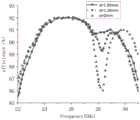
图6为本发明实施例一的应用于5G通信的宽频介质谐振天线在不同d值下的天线辐射效率曲线图;6 is a graph of antenna radiation efficiency curves of a broadband dielectric resonant antenna applied to 5G communication under different d values according to Embodiment 1 of the present invention;
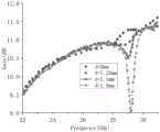
图7为本发明实施例一的应用于5G通信的宽频介质谐振天线在不同d值下的天线增益曲线图。FIG. 7 is an antenna gain curve diagram of the broadband dielectric resonant antenna applied to 5G communication under different values of d according to Embodiment 1 of the present invention.
附图标号说明:Explanation of reference numbers:
1、介质基板;1. Dielectric substrate;
2、顶层地层;21、耦合缝隙;211、第一缝隙;212、第二缝隙;2. Top stratum; 21. Coupling gap; 211. First gap; 212. Second gap;
3、介质谐振器;31、矩形体;311、矩形槽;32、介质臂;3. Dielectric resonator; 31. Rectangular body; 311. Rectangular slot; 32. Dielectric arm;
4、匹配微带线;4. Matching microstrip line;
5、底层地层;5. The bottom layer;
6、金属柱;6. Metal pillars;
7、芯片组件;7. Chip components;
d、第一虚拟平面与第二虚拟平面之间的距离。d. The distance between the first virtual plane and the second virtual plane.
具体实施方式Detailed ways
本发明目的实现、功能特点及优点将结合实施例,参照附图做进一步说明。The realization of the purpose, function and advantages of the present invention will be further described in conjunction with the embodiments and with reference to the accompanying drawings.
下面将结合本发明实施例中的附图,对本发明实施例中的技术方案进行清楚、完整地描述,显然,所描述的实施例仅仅是本发明的一部分实施例,而不是全部的实施例。基于本发明中的实施例,本领域普通技术人员在没有作出创造性劳动前提下所获得的所有其他实施例,都属于本发明保护的范围。The following will clearly and completely describe the technical solutions in the embodiments of the present invention with reference to the accompanying drawings in the embodiments of the present invention. Obviously, the described embodiments are only part of the embodiments of the present invention, not all of them. Based on the embodiments of the present invention, all other embodiments obtained by persons of ordinary skill in the art without creative efforts fall within the protection scope of the present invention.
需要说明,若本发明实施例中有涉及方向性指示诸如上、下、左、右、前、后……,则该方向性指示仅用于解释在某一特定姿态如附图所示下各部件之间的相对位置关系、运动情况等,如果该特定姿态发生改变时,则该方向性指示也相应地随之改变。It should be noted that if there are directional indications such as up, down, left, right, front, back, etc. in the embodiment of the present invention, the directional indications are only used to explain the position of each individual in a certain posture as shown in the attached figure. If the relative positional relationship, movement conditions, etc. between the components change, the directional indication will also change accordingly.
另外,若本发明实施例中有涉及“第一”、“第二”等的描述,则该“第一”、“第二”等的描述仅用于描述目的,而不能理解为指示或暗示其相对重要性或者隐含指明所指示的技术特征的数量。由此,限定有“第一”、“第二”的特征可以明示或者隐含地包括至少一个该特征。In addition, if there are descriptions involving "first", "second" and so on in the embodiments of the present invention, the descriptions of "first", "second" and so on are only for descriptive purposes, and should not be interpreted as indicating or implying Its relative importance or implicitly indicates the number of technical features indicated. Thus, the features defined as "first" and "second" may explicitly or implicitly include at least one of these features.
另外,若全文中出现的“和/或”的含义为,包括三个并列的方案,以“和/或”为例,包括方案,或方案,或和同时满足的方案。另外,各个实施例之间的技术方案可以相互结合,但是必须是以本领域普通技术人员能够实现为基础,当技术方案的结合出现相互矛盾或无法实现时应当认为这种技术方案的结合不存在,也不在本发明要求的保护范围之内。In addition, if the meaning of "and/or" appearing in the whole text is to include three parallel schemes, taking "and/or" as an example, it includes schemes, or schemes, or and schemes that are satisfied at the same time. In addition, the technical solutions of the various embodiments can be combined with each other, but it must be based on the realization of those skilled in the art. When the combination of technical solutions is contradictory or cannot be realized, it should be considered that the combination of technical solutions does not exist , nor within the scope of protection required by the present invention.
在本申请中,除非另有明确的规定和限定,术语“安装”、“相连”、“连接”、“固定”等术语应做广义理解,例如,可以是固定连接,也可以是可拆卸连接,或成一体;可以是机械连接,也可以是电连接;可以是直接相连,也可以通过中间媒介间接相连,可以是两个元件内部的连通或两个元件的相互作用关系。对于本领域的普通技术人员而言,可以根据具体情况理解上述术语在本申请中的具体含义。In this application, terms such as "installation", "connection", "connection" and "fixation" should be interpreted in a broad sense, for example, it can be a fixed connection or a detachable connection, unless otherwise clearly specified and limited. , or integrated; it can be mechanically connected or electrically connected; it can be directly connected or indirectly connected through an intermediary, and it can be the internal communication of two components or the interaction relationship between two components. Those of ordinary skill in the art can understand the specific meanings of the above terms in this application according to specific situations.
实施例一Embodiment one
请参照图1至图7,本发明的实施例一为:请结合图1至图3,一种应用于5G通信的宽频介质谐振天线,包括基板组件和介质谐振器3,所述基板组件包括介质基板1,所述介质基板1的顶面设有顶层地层2,所述顶层地层2上设有耦合缝隙21及所述介质谐振器3,即所述顶层地层2位于所述介质谐振器3与所述介质基板1之间,可选的,所述介质谐振器3胶粘固定在所述顶层地层2上,或者,所述介质谐振器3通过紧固结构件与所述介质基板1连接固定;所述介质基板1上设有用于通过所述耦合缝隙21为所述介质谐振器3馈电的匹配微带线4。Please refer to Figures 1 to 7, the first embodiment of the present invention is: Please combine Figures 1 to 3, a broadband dielectric resonant antenna applied to 5G communications, including a substrate assembly and a
所述介质谐振器3包括四个矩形体31和三个介质臂32,四个所述矩形体31呈一排间隔设置,相邻的两个所述矩形体31通过所述介质臂32相连,四个所述矩形体31与三个所述介质臂32为一体加工成型的一体式结构,所述矩形体31的中央设有矩形槽311;所述耦合缝隙21对应于所述矩形槽311的中央区域设置,所述耦合缝隙21整体呈工字型,所述耦合缝隙21包括第一缝隙211和两个第二缝隙212,所述第一缝隙211的两端分别连接有所述第二缝隙212,所述第一缝隙211与所述第二缝隙212的连通处位于所述第二缝隙212的中点,所述第一缝隙211的长度方向与所述矩形槽311的宽度方向一致,所述第二缝隙212的长度方向与所述矩形槽311的长度方向一致。本实施例中,所述介质谐振器3的介电常数为21。The
本实施例中,所述矩形体31的长为5.2mm,所述矩形体31的宽为3.3mm,所述矩形体31的高为0.85mm;所述矩形槽311的长度方向与所述矩形体31的长度方向一致,所述矩形槽311的高度方向与所述矩形体31的高度方向一致,所述矩形槽311的长为3.25mm,所述矩形槽311的宽为1.4mm,所述矩形槽311的的高为0.85mm。In this embodiment, the length of the
具体的,所述介质臂32呈矩形块状,所述介质臂32的中心线所在的第一虚拟平面与所述第一缝隙211长度方向的中线所在的第二虚拟平面之间的距离为d,1.26mm≤d≤1.5mm,所述第一虚拟平面与所述第二虚拟平面平行且分别垂直于所述顶层地层2。换个角度进行理解,俯视所述应用于5G通信的宽频介质谐振天线时,所述第一缝隙211长度方向的中线的延长线与所述介质臂32的中心线之间的距离即为所述d。Specifically, the
为方便加工制造,所述介质臂32的顶面与所述矩形体31的顶面平齐,所述介质臂32的底面与所述矩形体31的底面平齐。详细来说,三个所述介质臂32的中心线共线。To facilitate manufacturing, the top surface of the
作为优选的实施方式,所述匹配微带线4设于所述介质基板1内,将所述匹配微带线4设于所述介质基板1的内部可以减少外界信号干扰以及信号泄露,利于提高应用于5G通信的宽频介质谐振天线的性能表现。当然,在其他实施例中,所述匹配微带线4可以是设于所述介质基板1的底面的。As a preferred embodiment, the matching microstrip line 4 is arranged in the dielectric substrate 1, and setting the matching microstrip line 4 inside the dielectric substrate 1 can reduce external signal interference and signal leakage, which is beneficial to improve Performance of broadband dielectric resonant antennas applied to 5G communications. Certainly, in other embodiments, the matching microstrip line 4 may be provided on the bottom surface of the dielectric substrate 1 .
为进一步减少外界信号干扰,所述介质基板1的底面设有底层地层5,所述底层地层5与所述顶层地层2导通。优选的,所述底层地层5与所述顶层地层2通过金属柱6导通,所述匹配微带线4的两侧分别设有所述金属柱6。所述金属柱6可以是设于所述介质基板1上的金属化孔或柱状填充结构。In order to further reduce external signal interference, the bottom surface of the dielectric substrate 1 is provided with a
所述基板组件还包括设于所述介质基板1的底面的芯片组件7,所述芯片组件7包括射频芯片及分别与所述射频芯片电性连接的电源芯片与数字芯片,所述射频芯片连接所述匹配微带线4。The substrate assembly also includes a
接下来,说明下发明人的设计思路:Next, explain the inventor's design ideas:
先用超越方程设计DK(介电常数)为21的双模矩形介质谐振器(即所述矩形体),所述矩形体的长宽高为5.2X3.3X0.85mm,此时,所述矩形体的S参数曲线如图4中“未挖空”线条所示;The double-mode rectangular dielectric resonator (i.e. the rectangular body) that DK (dielectric constant) is 21 with transcendental equation design earlier, the length, width and height of the rectangular body is 5.2×3.3×0.85mm, at this moment, the rectangular The S-parameter curve of the body is shown in the "not hollowed out" line in Figure 4;
然后在矩形体上设置所述矩形槽以生成宽带天线,此时,所述矩形体的S参数曲线如图4中“挖空”线条所示;Then set the rectangular groove on the rectangular body to generate a broadband antenna, at this time, the S parameter curve of the rectangular body is shown in the "hollowed out" line in Figure 4;
从图4可以发现,双模式的矩形体的2个谐振点由TE111模式(图中左侧低点)和TE311模式(图中右侧低点)生成,但是其S参数表现成双频特性,在将矩形体中间挖去1.4X3.25X0.85mm体积形成矩形槽后,这时,耦合缝隙开始辐射生成了第三个谐振点,TE111、耦合缝隙、TE311这三个辐射模式生成了3个谐振点,使介质谐振器天线带宽覆盖(22.8-29.6GHz),其组阵后的S参数如图5所示,即图5为本实施例的应用于5G通信的宽频介质谐振天线的S参数图。It can be found from Figure 4 that the two resonance points of the dual-mode rectangular body are generated by the TE111 mode (the low point on the left in the figure) and the TE311 mode (the low point on the right in the figure), but its S parameters show dual-frequency characteristics. After digging out a volume of 1.4X3.25X0.85mm in the middle of the rectangular body to form a rectangular slot, at this time, the coupling gap starts to radiate to generate the third resonance point, and the three radiation modes of TE111, coupling gap, and TE311 generate three resonances Point, make the dielectric resonator antenna bandwidth coverage (22.8-29.6GHz), the S parameter after its formation is as shown in Figure 5, that is, Figure 5 is the S parameter diagram of the broadband dielectric resonant antenna applied to 5G communication in this embodiment .
接着用介质臂组阵,俯视状态下,介质臂到耦合缝隙长对称轴的距离d影响天线效率和增益,所以存在最佳距离范围。Then use the dielectric arm to form an array. In the state of looking down, the distance d from the dielectric arm to the long symmetry axis of the coupling slot affects the antenna efficiency and gain, so there is an optimal distance range.
如图6所示,宽频介质谐振器天线在28.6Ghz左右辐射效率会下降,因为在28.6GHz,介质臂产生了1个干扰天线的模式或者说场,在不同的d值的情况下,干扰程度不同,其中d=0mm的耦合最强,辐射效率下降最大;As shown in Figure 6, the radiation efficiency of the broadband dielectric resonator antenna will decrease around 28.6Ghz, because at 28.6GHz, the dielectric arm produces a mode or field that interferes with the antenna. Under different d values, the degree of interference different, the coupling of d=0mm is the strongest, and the radiation efficiency drops the most;
如图7所示,当d=1.89mm时,宽频介质谐振器天线在29.2GHZ增益掉得多,原因是天线的对称性被破坏最大,d=0mm时天线沿着缝隙高度对称,所以看d=0mm的增益曲线在29.2GHz基本没掉,且从图7可以看到,随着d的变大,天线增益越掉越多,当d=1.89mm时,增益下降尤为严重。As shown in Figure 7, when d=1.89mm, the gain of the broadband dielectric resonator antenna drops much at 29.2GHZ, because the symmetry of the antenna is destroyed the most. When d=0mm, the antenna is highly symmetrical along the slot, so look at d The gain curve of = 0mm basically does not drop at 29.2GHz, and it can be seen from Figure 7 that as d increases, the antenna gain drops more and more. When d = 1.89mm, the gain drop is particularly serious.
所以,综合图6和图7,介质臂到耦合缝隙长对称轴的距离最佳选择范围为1.26mm≤d≤1.5mm,最佳点值为d=1.26mm。Therefore, based on Fig. 6 and Fig. 7, the optimal selection range of the distance from the dielectric arm to the long symmetry axis of the coupling gap is 1.26mm≤d≤1.5mm, and the optimal point value is d=1.26mm.
上述仅为本发明的可选实施例,并非因此限制本发明的专利范围,凡是在本发明的发明构思下,利用本发明说明书及附图内容所作的等效结构变换,或直接/间接运用在其他相关的技术领域均包括在本发明的专利保护范围内。The above are only optional embodiments of the present invention, and are not intended to limit the patent scope of the present invention. Under the inventive concept of the present invention, the equivalent structural transformation made by using the description of the present invention and the contents of the accompanying drawings, or directly/indirectly used in Other relevant technical fields are all included in the patent protection scope of the present invention.
Claims (10)
Translated fromChinesePriority Applications (1)
| Application Number | Priority Date | Filing Date | Title |
|---|---|---|---|
| CN202310161351.XACN116315691A (en) | 2023-02-14 | 2023-02-14 | A broadband dielectric resonant antenna applied to 5G communication |
Applications Claiming Priority (1)
| Application Number | Priority Date | Filing Date | Title |
|---|---|---|---|
| CN202310161351.XACN116315691A (en) | 2023-02-14 | 2023-02-14 | A broadband dielectric resonant antenna applied to 5G communication |
Publications (1)
| Publication Number | Publication Date |
|---|---|
| CN116315691Atrue CN116315691A (en) | 2023-06-23 |
Family
ID=86791686
Family Applications (1)
| Application Number | Title | Priority Date | Filing Date |
|---|---|---|---|
| CN202310161351.XAPendingCN116315691A (en) | 2023-02-14 | 2023-02-14 | A broadband dielectric resonant antenna applied to 5G communication |
Country Status (1)
| Country | Link |
|---|---|
| CN (1) | CN116315691A (en) |
Citations (9)
| Publication number | Priority date | Publication date | Assignee | Title |
|---|---|---|---|---|
| CN103187624A (en)* | 2011-12-30 | 2013-07-03 | 财团法人工业技术研究院 | Dielectric antenna and antenna module |
| CN112542702A (en)* | 2020-11-24 | 2021-03-23 | 深圳市信维通信股份有限公司 | Dielectric resonator millimeter wave module and communication terminal |
| CN113193387A (en)* | 2021-03-19 | 2021-07-30 | 深圳市信维通信股份有限公司 | Dual-polarization dual-frequency dielectric resonator millimeter wave module and mobile terminal equipment |
| CN113437490A (en)* | 2021-06-07 | 2021-09-24 | 深圳市信维通信股份有限公司 | Ultra-wideband dielectric resonator antenna and communication equipment |
| CN215008573U (en)* | 2021-03-26 | 2021-12-03 | 深圳市信维通信股份有限公司 | Integrated dual-frequency dielectric resonant antenna module and electronic equipment |
| CN215266650U (en)* | 2021-04-30 | 2021-12-21 | 深圳市信维通信股份有限公司 | Integrated 5G millimeter wave dual-frequency dielectric resonator antenna module and electronic equipment |
| CN114865274A (en)* | 2022-03-18 | 2022-08-05 | 深圳市信维通信股份有限公司 | Integrated dual-frequency dielectric resonator antenna module and electronic equipment |
| CN217281204U (en)* | 2022-03-10 | 2022-08-23 | 深圳市信维通信股份有限公司 | Multiplexing 5G millimeter wave dielectric resonator antenna |
| CN219513348U (en)* | 2023-02-14 | 2023-08-11 | 深圳市信维通信股份有限公司 | Broadband dielectric resonant antenna applied to 5G communication |
- 2023
- 2023-02-14CNCN202310161351.XApatent/CN116315691A/enactivePending
Patent Citations (9)
| Publication number | Priority date | Publication date | Assignee | Title |
|---|---|---|---|---|
| CN103187624A (en)* | 2011-12-30 | 2013-07-03 | 财团法人工业技术研究院 | Dielectric antenna and antenna module |
| CN112542702A (en)* | 2020-11-24 | 2021-03-23 | 深圳市信维通信股份有限公司 | Dielectric resonator millimeter wave module and communication terminal |
| CN113193387A (en)* | 2021-03-19 | 2021-07-30 | 深圳市信维通信股份有限公司 | Dual-polarization dual-frequency dielectric resonator millimeter wave module and mobile terminal equipment |
| CN215008573U (en)* | 2021-03-26 | 2021-12-03 | 深圳市信维通信股份有限公司 | Integrated dual-frequency dielectric resonant antenna module and electronic equipment |
| CN215266650U (en)* | 2021-04-30 | 2021-12-21 | 深圳市信维通信股份有限公司 | Integrated 5G millimeter wave dual-frequency dielectric resonator antenna module and electronic equipment |
| CN113437490A (en)* | 2021-06-07 | 2021-09-24 | 深圳市信维通信股份有限公司 | Ultra-wideband dielectric resonator antenna and communication equipment |
| CN217281204U (en)* | 2022-03-10 | 2022-08-23 | 深圳市信维通信股份有限公司 | Multiplexing 5G millimeter wave dielectric resonator antenna |
| CN114865274A (en)* | 2022-03-18 | 2022-08-05 | 深圳市信维通信股份有限公司 | Integrated dual-frequency dielectric resonator antenna module and electronic equipment |
| CN219513348U (en)* | 2023-02-14 | 2023-08-11 | 深圳市信维通信股份有限公司 | Broadband dielectric resonant antenna applied to 5G communication |
Similar Documents
| Publication | Publication Date | Title |
|---|---|---|
| CN110676589B (en) | A high-gain differential dual-polarized dielectric patch antenna based on higher-order modes | |
| CN107634335A (en) | Millimeter wave array antenna based on multi-layer structure | |
| CN113097731B (en) | Millimeter wave filtering antenna based on ridge waveguide resonant cavity | |
| CN113922075B (en) | A slow-wave substrate integrated waveguide duplex antenna based on high-order modes | |
| CN103618138B (en) | Miniaturized differential microstrip antenna | |
| CN111834739B (en) | Four-mode broadband high-gain differential dielectric resonator antenna | |
| CN112886234B (en) | Microwave millimeter wave coplanar common-caliber antenna based on embedded structure | |
| CN115995678A (en) | A Millimeter Wave Broadband Substrate Integrated Mixed Dielectric Resonator Antenna | |
| CN114256616A (en) | An antenna unit and antenna array | |
| CN111541024A (en) | Radiating unit, antenna, antenna array and radar using the antenna array | |
| CN219513348U (en) | Broadband dielectric resonant antenna applied to 5G communication | |
| Tang et al. | Differentially SIW TE 20-mode Fed substrate integrated filtering dielectric resonator antenna for 5G millimeter wave application | |
| CN111525218A (en) | High-performance dielectric waveguide filter with six trapped waves and communication equipment | |
| CN116315691A (en) | A broadband dielectric resonant antenna applied to 5G communication | |
| CN113328241A (en) | Low-profile broadband wide-angle scanning tightly-coupled antenna unit and array | |
| CN115603054A (en) | Coupling spherical cavity waveguide antenna | |
| JP7534053B2 (en) | Dual polarized antenna, related antenna module and electronic device | |
| WO2024139652A1 (en) | Antenna apparatus and feed network assembly | |
| CN215816437U (en) | Antenna array for traffic radar | |
| CN216251147U (en) | A half-hole feed patch antenna | |
| CN215771561U (en) | Dual-frequency dielectric antenna and base station antenna array | |
| CN114725686B (en) | Logarithmic periodic antenna based on half-module rectangular metal waveguide excitation | |
| CN113471705A (en) | Grounded metal column coupled dielectric resonator antenna | |
| CN221928529U (en) | Microstrip changes waveguide structure and radar | |
| CN217239753U (en) | Symmetrical soft surface coupling suppression structure |
Legal Events
| Date | Code | Title | Description |
|---|---|---|---|
| PB01 | Publication | ||
| PB01 | Publication | ||
| SE01 | Entry into force of request for substantive examination | ||
| SE01 | Entry into force of request for substantive examination |