CN116313610A - Wall switch, socket and combination thereof - Google Patents
Wall switch, socket and combination thereofDownload PDFInfo
- Publication number
- CN116313610A CN116313610ACN202310290652.2ACN202310290652ACN116313610ACN 116313610 ACN116313610 ACN 116313610ACN 202310290652 ACN202310290652 ACN 202310290652ACN 116313610 ACN116313610 ACN 116313610A
- Authority
- CN
- China
- Prior art keywords
- mounting
- module
- plate
- socket
- hole
- Prior art date
- Legal status (The legal status is an assumption and is not a legal conclusion. Google has not performed a legal analysis and makes no representation as to the accuracy of the status listed.)
- Pending
Links
- 238000009434installationMethods0.000claimsdescription37
- 230000007935neutral effectEffects0.000claimsdescription17
- 239000004020conductorSubstances0.000claimsdescription15
- 238000003825pressingMethods0.000claimsdescription5
- 230000037431insertionEffects0.000claims1
- 238000003780insertionMethods0.000claims1
- 238000003032molecular dockingMethods0.000claims1
- 238000004519manufacturing processMethods0.000abstractdescription12
- 230000006835compressionEffects0.000description5
- 238000007906compressionMethods0.000description5
- 230000000712assemblyEffects0.000description3
- 238000000429assemblyMethods0.000description3
- 238000005516engineering processMethods0.000description2
- 239000000047productSubstances0.000description2
- 230000002787reinforcementEffects0.000description2
- 230000009286beneficial effectEffects0.000description1
- 238000010586diagramMethods0.000description1
- 230000000694effectsEffects0.000description1
- 239000012467final productSubstances0.000description1
- 239000002184metalSubstances0.000description1
- 238000000034methodMethods0.000description1
- 230000000149penetrating effectEffects0.000description1
Images


Classifications
- H—ELECTRICITY
- H01—ELECTRIC ELEMENTS
- H01H—ELECTRIC SWITCHES; RELAYS; SELECTORS; EMERGENCY PROTECTIVE DEVICES
- H01H23/00—Tumbler or rocker switches, i.e. switches characterised by being operated by rocking an operating member in the form of a rocker button
- H01H23/02—Details
- H01H23/04—Cases; Covers
- H—ELECTRICITY
- H01—ELECTRIC ELEMENTS
- H01H—ELECTRIC SWITCHES; RELAYS; SELECTORS; EMERGENCY PROTECTIVE DEVICES
- H01H23/00—Tumbler or rocker switches, i.e. switches characterised by being operated by rocking an operating member in the form of a rocker button
- H01H23/02—Details
- H01H23/08—Bases; Stationary contacts mounted thereon
- H—ELECTRICITY
- H01—ELECTRIC ELEMENTS
- H01H—ELECTRIC SWITCHES; RELAYS; SELECTORS; EMERGENCY PROTECTIVE DEVICES
- H01H23/00—Tumbler or rocker switches, i.e. switches characterised by being operated by rocking an operating member in the form of a rocker button
- H01H23/02—Details
- H01H23/12—Movable parts; Contacts mounted thereon
- H01H23/16—Driving mechanisms
- H—ELECTRICITY
- H01—ELECTRIC ELEMENTS
- H01H—ELECTRIC SWITCHES; RELAYS; SELECTORS; EMERGENCY PROTECTIVE DEVICES
- H01H23/00—Tumbler or rocker switches, i.e. switches characterised by being operated by rocking an operating member in the form of a rocker button
- H01H23/28—Tumbler or rocker switches, i.e. switches characterised by being operated by rocking an operating member in the form of a rocker button with three operating positions
- H—ELECTRICITY
- H01—ELECTRIC ELEMENTS
- H01R—ELECTRICALLY-CONDUCTIVE CONNECTIONS; STRUCTURAL ASSOCIATIONS OF A PLURALITY OF MUTUALLY-INSULATED ELECTRICAL CONNECTING ELEMENTS; COUPLING DEVICES; CURRENT COLLECTORS
- H01R13/00—Details of coupling devices of the kinds covered by groups H01R12/70 or H01R24/00 - H01R33/00
- H01R13/02—Contact members
- H01R13/10—Sockets for co-operation with pins or blades
- H—ELECTRICITY
- H01—ELECTRIC ELEMENTS
- H01R—ELECTRICALLY-CONDUCTIVE CONNECTIONS; STRUCTURAL ASSOCIATIONS OF A PLURALITY OF MUTUALLY-INSULATED ELECTRICAL CONNECTING ELEMENTS; COUPLING DEVICES; CURRENT COLLECTORS
- H01R13/00—Details of coupling devices of the kinds covered by groups H01R12/70 or H01R24/00 - H01R33/00
- H01R13/46—Bases; Cases
- H01R13/502—Bases; Cases composed of different pieces
- H01R13/506—Bases; Cases composed of different pieces assembled by snap action of the parts
- H—ELECTRICITY
- H01—ELECTRIC ELEMENTS
- H01R—ELECTRICALLY-CONDUCTIVE CONNECTIONS; STRUCTURAL ASSOCIATIONS OF A PLURALITY OF MUTUALLY-INSULATED ELECTRICAL CONNECTING ELEMENTS; COUPLING DEVICES; CURRENT COLLECTORS
- H01R13/00—Details of coupling devices of the kinds covered by groups H01R12/70 or H01R24/00 - H01R33/00
- H01R13/73—Means for mounting coupling parts to apparatus or structures, e.g. to a wall
- H01R13/74—Means for mounting coupling parts in openings of a panel
- H01R13/741—Means for mounting coupling parts in openings of a panel using snap fastening means
- Y—GENERAL TAGGING OF NEW TECHNOLOGICAL DEVELOPMENTS; GENERAL TAGGING OF CROSS-SECTIONAL TECHNOLOGIES SPANNING OVER SEVERAL SECTIONS OF THE IPC; TECHNICAL SUBJECTS COVERED BY FORMER USPC CROSS-REFERENCE ART COLLECTIONS [XRACs] AND DIGESTS
- Y02—TECHNOLOGIES OR APPLICATIONS FOR MITIGATION OR ADAPTATION AGAINST CLIMATE CHANGE
- Y02B—CLIMATE CHANGE MITIGATION TECHNOLOGIES RELATED TO BUILDINGS, e.g. HOUSING, HOUSE APPLIANCES OR RELATED END-USER APPLICATIONS
- Y02B20/00—Energy efficient lighting technologies, e.g. halogen lamps or gas discharge lamps
- Y02B20/40—Control techniques providing energy savings, e.g. smart controller or presence detection
Landscapes
- Switch Cases, Indication, And Locking (AREA)
Abstract
Description
Translated fromChinese技术领域technical field
本申请涉及墙壁开关的领域,尤其是涉及一种墙壁开关、插座及其组合。The present application relates to the field of wall switches, in particular to a wall switch, a socket and a combination thereof.
背景技术Background technique
墙壁开关是指安装在墙壁上使用的电器开关,用来接通和断开电路的,控制照明灯的开关,狭义上的电工产品通常仅指建筑电气中的开关、插座。A wall switch refers to an electrical switch installed on the wall, used to turn on and off the circuit, and to control the switch of the lighting lamp. Electrical products in a narrow sense usually only refer to switches and sockets in building electrical appliances.
公告号为CN217788263U的专利公开了墙壁三开控制开关,其包括开关外壳和内部壳体,内部壳体中安装有三组通断元件,开关外壳上设置有三个按键以分别控制三组通断元件对不同电路进行控制。The patent with the notification number CN217788263U discloses a wall three-opening control switch, which includes a switch housing and an inner housing. Three groups of on-off elements are installed in the inner housing, and three buttons are arranged on the switch housing to control the three groups of on-off elements. Controlled by different circuits.
根据市场需求,墙壁开关通常采用单开、二开、三开以满足不同的电路控制需求,或者以墙壁开关、插座的组合形式提供,但是针对上述多种开关的形式,每种开关都需要制作相应不同结构的内部壳体,例如上述相关技术,对于生产制造而言,需要较多的生产成本,有待改进。According to market demand, wall switches are usually single-open, double-open, and three-open to meet different circuit control requirements, or provided in the form of a combination of wall switches and sockets, but for the above-mentioned forms of various switches, each switch needs to be manufactured Correspondingly different structures of the inner housing, such as the above-mentioned related technologies, require more production costs for production and manufacture, and need to be improved.
发明内容Contents of the invention
为了提高配件的通用性,本申请提供一种墙壁开关、插座及其组合。In order to improve the versatility of accessories, the present application provides a wall switch, a socket and a combination thereof.
第一方面,本申请提供的一种墙壁开关采用如下的技术方案:In the first aspect, a wall switch provided by the application adopts the following technical solution:
一种墙壁开关,包括安装板,所述安装板上贯穿有安装孔,安装孔内设置有通断组件,所述安装板上设置有控制通断组件的按键面板,所述通断组件和按键面板的数量相对应且设置为至少一个,所述通断组件包括安装座、设置于安装座内的通断模块、对通断模块进行限位固定的盖板,所述盖板贯穿有通孔,所述通断组件还包括控制通断模块切换电路的控制杆,所述控制杆从通孔穿出并与盖板转动连接,所述控制杆与按键面板联动连接,所述安装座和安装板卡接配合。A wall switch, comprising a mounting plate, a mounting hole is penetrated on the mounting plate, an on-off assembly is arranged in the installation hole, a key panel for controlling the on-off assembly is arranged on the mounting plate, the on-off assembly and the key The number of panels corresponds to at least one. The on-off assembly includes a mounting seat, an on-off module arranged in the mounting seat, and a cover plate for limiting and fixing the on-off module. The cover plate is penetrated with a through hole , the on-off assembly also includes a control rod for controlling the switching circuit of the on-off module, the control rod passes through the through hole and is rotatably connected with the cover plate, the control rod is linked with the key panel, the mounting seat and the installation The board fits together.
通过采用上述技术方案,通过将通断组件进行配件标准化,并通过卡接配合的方式安装在安装板上,当需要生产不同组合形式的墙壁开关时,取相应数量的通断组件组合装入安装板上即可。相较于现有技术而言,有效降低了生产成本,及提高生产效率。By adopting the above technical scheme, standardizing the on-off components and installing them on the installation board by snap-fitting, when it is necessary to produce wall switches in different combinations, take the corresponding number of on-off components and assemble them for installation on the board. Compared with the prior art, the production cost is effectively reduced and the production efficiency is improved.
可选的,所述安装板的一侧设置有两个卡接扣板,两个所述卡接扣板分别位于安装座长度方向的两侧,每个卡接扣板上均开设有和通断组件数量相对应的扣合孔,所述安装座长度方向的两端均设置有扣合孔相卡接的扣合块。Optionally, one side of the mounting plate is provided with two snap-in buckle plates, and the two snap-in buckle plates are respectively located on both sides of the length direction of the mounting seat. There are fastening holes corresponding to the number of broken components, and fastening blocks that are engaged with the fastening holes are provided at both ends of the mounting seat in the length direction.
通过采用上述技术方案,通过扣合块和卡接扣板的相互扣合,对安装座长度方向的两端进行限位,相较于宽度方向上卡接固定,具有更良好的稳定性。By adopting the above technical solution, the two ends of the installation seat in the length direction are limited by the mutual buckling of the buckling block and the snapping buckle plate, which has better stability than the snapping and fixing in the width direction.
可选的,所述安装板的一侧设置有两个固定板,两个所述固定板分别和安装座宽度方向的两相对侧壁相贴合。Optionally, two fixing plates are provided on one side of the mounting plate, and the two fixing plates are attached to two opposite side walls in the width direction of the mounting seat respectively.
通过采用上述技术方案,进一步对安装座宽度方向的两侧进行限位,提高安装座的安装稳定性。By adopting the above technical solution, the two sides in the width direction of the installation seat are further limited, and the installation stability of the installation seat is improved.
可选的,所述墙壁开关为三控开关,所述安装座内的通断模块设置为三组,将三组通断模块分别定义为第一通断模块、第二通断模块、第三通断模块,所述第一通断模块和第二通断模块并排设置,所述第三通断模块和第一通断模块并列设置,所述安装座于第三通断模块的并排处设置有让位槽,当所述通断组件的数量大于一个时,两个安装座之间相互错位形成方形结构。Optionally, the wall switch is a three-control switch, and the on-off modules in the mounting base are set in three groups, and the three groups of on-off modules are respectively defined as the first on-off module, the second on-off module, the third on-off module The on-off module, the first on-off module and the second on-off module are arranged side by side, the third on-off module and the first on-off module are arranged side by side, and the mounting seat is arranged on the side of the third on-off module There are relief slots, and when the number of on-off components is more than one, the two installation seats are misaligned to form a square structure.
通过采用上述技术方案,通过对通断模块进行特定排列,使得安装座形成了特定了类似于L形的结构,一方面降低了通断组件的整体体积、一方面在多个通断组件进行组合时可以进一步降低占用面积。By adopting the above-mentioned technical scheme and by arranging the on-off modules in a specific way, the mounting base forms a specific L-shaped structure, which reduces the overall volume of the on-off components on the one hand, and combines multiple on-off components on the one hand. The occupied area can be further reduced.
可选的,所述控制杆背离安装座的一端设置有联动板,所述联动板上开设有卡接孔,所述按键面板朝向联动板的一侧设置有和卡接孔相扣合的固定扣板。Optionally, a linkage plate is provided at the end of the control rod away from the mounting seat, and a locking hole is opened on the linkage plate, and a fixed buckle plate that is engaged with the locking hole is provided on the side of the button panel facing the linkage plate .
通过采用上述技术方案,确保按键面板和联动板之间的配合稳定性。By adopting the above technical solution, the cooperation stability between the button panel and the linkage plate is ensured.
第二方面,本申请提供的一种墙壁插座采用如下的技术方案:In the second aspect, a wall socket provided by the present application adopts the following technical solution:
一种墙壁插座,包括安装板,所述安装板贯穿有安装孔,安装孔内设置有接电组件,安装板上设置有插座面板,所述接电组件包括安装壳体、设置于安装壳体内的接电模块、对接电模块进行限位固定的插座盖,所述安装壳体和安装板卡接配合。A wall socket, comprising a mounting plate, the mounting plate is penetrated with a mounting hole, an electrical connection assembly is arranged in the installation hole, a socket panel is arranged on the mounting plate, the electrical connection assembly includes a mounting shell, and is arranged in the mounting shell The power connection module, the socket cover for limiting and fixing the power connection module, and the installation shell and the installation plate are clamped and matched.
通过采用上述技术方案,通过将接电组件进行配件标准化,并通过卡接配合的方式安装在安装板上,当需要生产不同组合形式的墙壁插座时,取相应数量的接电组件组合装入安装板上即可。相较于现有技术而言,有效降低了生产成本,及提高生产效率。By adopting the above technical scheme, standardizing the accessories of the power connection components, and installing them on the installation board through snap-fitting, when it is necessary to produce wall sockets in different combinations, take the corresponding number of power connection components and assemble them into the installation on the board. Compared with the prior art, the production cost is effectively reduced and the production efficiency is improved.
可选的,所述接电模块包括三个结构相同的接线座、地线导电件、结构相同且呈对称设置的零线导电件和火线导电件,三个所述接线座分别定义为零线座、地线座、火线座并分别和零线导电件、地线导电件、火线导电件电连接,所述零线导电件包括二插接电部和三插接电部,所述二插接电部和三插接电部之间通过导电片相连接,所述导电片呈竖直设置,所述导电片的中部设置有插入零线座的接电板。Optionally, the power connection module includes three terminal blocks with the same structure, ground wire conductors, zero line conductors and live wire conductors with the same structure and arranged symmetrically, and the three terminal blocks are respectively defined as neutral wires seat, ground wire seat, and live wire seat and are electrically connected to the neutral wire conductive part, ground wire conductive part, and live wire conductive part respectively. The neutral wire conductive part includes two plug-in electric parts and three plug-in electric parts. The electric connection part and the three plug-in electric parts are connected through a conductive sheet, and the conductive sheet is arranged vertically, and the middle part of the conductive sheet is provided with a connection plate inserted into the neutral wire holder.
通过采用上述技术方案,通过对接电模块进行特定排列,有效降低接电组件的体积,进而提高组合装配数量。By adopting the above-mentioned technical solution and by arranging the power-connection modules in a specific way, the volume of the power-connection components can be effectively reduced, thereby increasing the assembly quantity.
可选的,所述插座盖朝向安装壳体的一侧设置有压紧板组,所述压紧板组同时压紧地线导电件、火线导电件、零线导电件和对应接线座的连接处。Optionally, the side of the socket cover facing the installation housing is provided with a pressing plate set, and the pressing plate set simultaneously presses the connection of the ground conductor, the live conductor, the neutral conductor and the corresponding terminal block place.
通过采用上述技术方案,提高整体内部装配稳定性。By adopting the above technical solution, the overall internal assembly stability is improved.
第三方面,本申请提供的一种墙壁开关、插座组合采用如下的技术方案:In the third aspect, a wall switch and socket combination provided by the application adopts the following technical solution:
一种墙壁开关、插座组合,包括安装板,所述安装板上开设有至少两个安装孔,一所述安装孔安装有如权利要求1-5任一项所述的若干通断组件和按键面板,另一所述安装孔安装有如权利要求6-8任一项所述的接电组件。A wall switch and socket combination, comprising a mounting plate, at least two mounting holes are opened on the mounting plate, and a plurality of on-off components and key panels according to any one of claims 1-5 are installed in one of the mounting holes , the other said mounting hole is installed with the electrical connection assembly as described in any one of claims 6-8.
通过采用上述技术方案,通过讲通断组件和接电组件进行配件标准化,在安装板上开设所需规格的安装孔即可完成相应的组合装配,有效降低生产成本并提高生产效率。By adopting the above-mentioned technical scheme, the on-off components and the power connection components are standardized, and the corresponding assembly can be completed by opening the installation holes of the required specifications on the mounting plate, which effectively reduces the production cost and improves the production efficiency.
综上所述,本申请包括以下至少一种有益技术效果:In summary, the present application includes at least one of the following beneficial technical effects:
1.通过将通断组件及接电组件进行配件标准化,并通过卡接配合的方式安装在安装板上,当需要生产不同组合形式的墙壁开关、插座时,取相应数量的通断组件和接电组件进而组合装入安装板上即可。相较于现有技术而言,有效降低了生产成本,及提高生产效率;1. By standardizing the accessories of on-off components and power-connection components, and installing them on the installation board by snap-fitting, when it is necessary to produce wall switches and sockets in different combinations, take the corresponding number of on-off components and connection components. The electrical components can then be combined and loaded onto the mounting board. Compared with the existing technology, the production cost is effectively reduced and the production efficiency is improved;
2.通过对通断模块进行特定排列,使得安装座形成了特定了类似于L形的结构,一方面降低了通断组件的整体体积、一方面在多个通断组件进行组合时可以进一步降低占用面积;2. Through the specific arrangement of the on-off modules, the mounting base forms a specific L-shaped structure, which reduces the overall volume of the on-off components on the one hand, and can further reduce the overall volume of the on-off components when multiple on-off components are combined. occupied area;
3.通过对接电模块进行特定排列,有效降低接电组件的体积,进而提高组合装配数量。3. Through the specific arrangement of the power-connection modules, the volume of the power-connection components can be effectively reduced, thereby increasing the number of combined assemblies.
附图说明Description of drawings
图1是本申请实施例1的爆炸视图。Fig. 1 is an exploded view of
图2是本申请实施例1中通断组件的爆炸视图。Fig. 2 is an exploded view of the on-off assembly in
图3是本申请实施例1中通断组件去除安装座和盖板后的结构示意图。Fig. 3 is a schematic structural view of the on-off assembly in
图4是本申请实施例2的爆炸视图。Fig. 4 is an exploded view of
图5是本申请实施例3的爆炸视图。Fig. 5 is an exploded view of
图6是本申请实施例4的爆炸视图。Fig. 6 is an exploded view of
图7是本申请实施例5的爆炸视图。Fig. 7 is an exploded view of
图8是本申请实施例5中接电模块的结构示意图。FIG. 8 is a schematic structural diagram of the power connection module in
图9是本申请实施例6的爆炸视图。Fig. 9 is an exploded view of
图10是本申请实施例7的爆炸视图。Fig. 10 is an exploded view of Embodiment 7 of the present application.
图11是本申请实施例8的爆炸视图。Fig. 11 is an exploded view of
图12是本申请实施例9的正视图。Fig. 12 is a front view of Embodiment 9 of the present application.
图13是本申请实施例10的正视图。Fig. 13 is a front view of
图14是本申请实施例11的正视图。Fig. 14 is a front view of
图15是本申请实施例12的正视图。Fig. 15 is a front view of
图16是本申请实施例13的正视图。Fig. 16 is a front view of
附图标记说明:1、安装板;2、通断组件;21、安装座;22、通断模块;23、盖板;24、压紧块;25、控制杆;26、联动板;3、按键面板;4、安装孔;5、卡接扣板;6、扣合块;7、让位槽;8、固定扣板;9、接电组件;91、安装壳体;92、接电模块;921、接线座;922、地线导电件;923、零线导电件;924、火线导电件;93、插座盖;94、压紧板组;10、插座面板;11、二插接电部;12、三插接电部;13、导电片;14、接电板。Explanation of reference signs: 1. Mounting plate; 2. On-off assembly; 21. Mounting seat; 22. On-off module; 23. Cover plate; 24. Compression block; 25. Control rod; 26. Linkage plate; 3. Button panel; 4. Mounting hole; 5. Clamping buckle plate; 6. Fastening block; 7. Relief groove; 8. Fixed buckle plate; 9. Power connection component; ; 921, wiring seat; 922, ground wire conductive part; 923, zero line conductive part; 924, fire wire conductive part; 93, socket cover; 94, pressing plate group; 10, socket panel; ; 12, three plug-in electrical parts; 13, conductive sheet; 14, connecting plate.
具体实施方式Detailed ways
以下结合附图1-9对本申请作进一步详细说明。The present application will be described in further detail below in conjunction with accompanying drawings 1-9.
实施例Example
实施例1Example 1
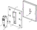
本申请实施例公开了一种墙壁开关,具体为单开三控墙壁开关。参照图1,墙壁开关包括安装板1、通断组件2、控制通断组件2切换电路的按键面板3。安装板1的中部贯穿有和通断组件2的形状相契合的安装孔4,通断组件2从安装板1背离按键面板3的一侧装入安装孔4内。The embodiment of the application discloses a wall switch, specifically a single-open three-control wall switch. Referring to FIG. 1 , the wall switch includes a mounting
参照图1,安装板1朝向通断组件2的一侧一体成型有两个卡接扣板5和两个加固板,两个卡接扣板5和两个加固板分别位于安装孔4开口的四周。两个卡接扣板5分别位于通断组件2长度方向的两端,两个固定板分别位于通断组件2宽度方向的两端。其中,卡接扣板5上贯穿有扣合孔。Referring to Fig. 1, the side of the mounting
参照图1、图2,通断组件2包括安装座21,安装座21长度方向的两端一体成型有和扣合孔相卡接的扣合块6。安装座21宽度方向的两侧壁分别和两个固定板侧壁相互贴合。Referring to FIG. 1 and FIG. 2 , the on-off
参照图2、图3,安装座21内设置有三组通断模块22,三组通断模块22分别定义为第一通断模块、第二通断模块、第三通断模块,第一通断模块和第二通断模块并排设置,第三通断模块和第一通断模块并列设置。安装座21于第三通断模块的并排处设置有让位槽7,使得安装座21的形状呈类似于L形设置。Referring to Fig. 2 and Fig. 3, three groups of on-off
参照图1、图 2、图3,安装座21朝向按键面板3的一侧设置有盖板23,盖板23朝向通断模块22的一侧一体连接有三个压紧块24,三个压紧块24分别对三组通断模块22进行压紧固定。盖板23贯穿有通孔,安装座21内设置有控制三组通断模块22切换电路的控制杆25,该控制杆25的端部从通孔中伸出。控制杆25于安装座21外的一端一体连接有联动板26,该联动板26和盖板23转动连接。Referring to Fig. 1, Fig. 2 and Fig. 3, the mounting
参照图1、图2,联动板26的两侧贯穿有卡接孔,按键面板3朝向联动板26的一侧一体连接有固定条,该固定条的两端均一体连接有固定扣板8,两个固定扣板8分别和相应的卡接孔相互卡接扣合。Referring to Fig. 1 and Fig. 2, the two sides of the
实施例2Example 2
参照图4,本申请实施例公开了一种墙壁开关,具体为双开三控墙壁开关。与实施例1的区别在于,通断组件2和按键面板3均设置为两组,且两个通断组件2的安装座21之间相互错位拼装形成方形结构。卡接扣板5上贯穿有两个扣合孔,分别供两个安装座21进行卡接固定。Referring to FIG. 4 , the embodiment of the present application discloses a wall switch, specifically a double-opening three-control wall switch. The difference from
实施例3Example 3
参照图5,本申请实施例公开了一种墙壁开关,具体为三开三控墙壁开关。与实施例1的区别在于,通断组件2和按键面板3均设置为三组,三个通断组件2采用并排排列的方式进行安装,在其他实施例中,还可以采用实施例1、2相结合的方式进行安装。其中,卡接扣板5上贯穿有三个扣合孔,分别供三个安装座21进行卡接固定。Referring to FIG. 5 , the embodiment of the present application discloses a wall switch, specifically a three-open three-control wall switch. The difference from
实施例4Example 4
参照图6,本申请实施例公开了一种墙壁开关,具体为四开三控墙壁开关。与实施例1的区别在于,通断组件2和按键面板3均设置为四组,且两个通断组件2的安装座21之间相互错位拼装形成方形结构。其中,卡接扣板5上贯穿有四个扣合孔,分别供四个安装座21进行卡接固定。Referring to FIG. 6 , the embodiment of the present application discloses a wall switch, specifically a four-open three-control wall switch. The difference from
实施例5Example 5
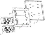
参照图7,本申请实施例公开了一种墙壁插座,其包括安装板1、接电组件9及插座面板10,安装板1的中部贯穿有和接电组件9的形状相契合的安装孔4,接电组件9从安装板1背离插座面板10的一侧装入安装孔4内,插座面板10和安装板1卡接配合。Referring to FIG. 7 , the embodiment of the present application discloses a wall socket, which includes a mounting
参照图7,安装板1朝向接电组件9的一侧一体成型有四个卡接扣板5,四个卡接扣板5以两个为一组分别位于安装孔4开口的两相对侧,且两组卡接扣板5分别位于接电组件9长度方向的两端。其中,卡接扣板5上贯穿有扣合孔。Referring to FIG. 7 , the side of the mounting
参照图7、图8,接电组件9包括安装壳体91,安装壳体91的两相对侧壁上均一体连接有两个卡扣,四个卡扣分别与四个卡接扣板5相互卡接扣合。Referring to Fig. 7 and Fig. 8, the power connection assembly 9 includes an
接电组件9还包括设置于安装壳体91内的接电模块92,接电模块92包括三个结构相同的接线座921,以及地线导电件922,以及结构相同且呈对称设置的零线导电件923和火线导电件924。三个接线座921呈并排设置并依次定义为零线座、地线座、火线座,并分别和零线导电件923、地线导电件922、火线导电件924电连接。The power connection assembly 9 also includes a
零线导电件923包括二插接电部11和三插接电部12,二插接电部11和三插接电部12之间通过导电片13相连接,二插接电部11、导电片13、三插接电部12采用导电金属一体成型设置。其中,导电片13呈竖直设置,且导电片13的中部一体连接有接电板14,接电板14呈弯折设置并插入零线座内。The
参照图7、图8,安装壳体91上卡扣连接有插座盖93,插座盖93朝向安装壳体91的一侧一体连接有压紧板组94,压紧板组94同时压紧地线导电件922、火线导电件924、零线导电件923和对应接线座921的连接处。进而保证接电模块92的安装稳定性及电连接性能。Referring to Fig. 7 and Fig. 8, a
实施例6Example 6
参照图9,本申请实施例公开了一种墙壁插座,与实施例5的区别在于,安装板1贯穿有两个安装孔4,两个安装孔4内均安装有接电组件9。Referring to FIG. 9 , the embodiment of the present application discloses a wall socket. The difference from
实施例7Example 7
参照图10,本申请实施例公开了一种墙壁插座,与实施例6的区别在于,两个接电组件9的安装方向相反。Referring to FIG. 10 , the embodiment of the present application discloses a wall socket. The difference from
实施例8Example 8
参照图11,本申请实施例公开了一种墙壁开关、插座的组合,其包括安装板1,安装板1贯穿有两个安装孔4,两个安装孔4内分别对应安装有实施例1中的通断组件2和实施例5中的接电组件9,其安装方式为卡接配合。安装板1上卡接配合有对应通断组件2和接电组件9的按键面板3和插座面板10。Referring to Fig. 11 , the embodiment of the present application discloses a combination of a wall switch and a socket, which includes a mounting
在本实施例中为一组通断组件2和按键面板3,在其他实施例中,通断组件2和按键面板3可以设置为多组。In this embodiment, it is a group of on-
实施例9Example 9
参照图12,本申请实施例公开了一种墙壁插座,和实施例8的区别在于,将通断组件2替换为电视信号接口组件。Referring to FIG. 12 , the embodiment of the present application discloses a wall socket, and the difference from
实施例10Example 10
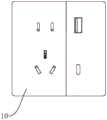
参照图13,本申请实施例公开了一种墙壁插座,和实施例8的区别在于,将通断组件2替换为网络信号接口组件。Referring to FIG. 13 , the embodiment of the present application discloses a wall socket. The difference from
实施例11Example 11
参照图14,本申请实施例公开了一种墙壁开关、插座的组合,和实施例8的区别在于,将通断组件2替换为定时器组件。Referring to FIG. 14 , the embodiment of the present application discloses a combination of a wall switch and a socket, and the difference from
实施例12Example 12
参照图15,本申请实施例公开了一种墙壁插座,和实施例8的区别在于,将通断组件2替换为1A1C插座组件。Referring to FIG. 15 , the embodiment of the present application discloses a wall socket, the difference from
实施例13Example 13
参照图16,本申请实施例公开了一种墙壁开关、插座的组合,和实施例8的区别在于,将通断组件2替换为人体红外开关组件。Referring to FIG. 16 , the embodiment of the present application discloses a combination of a wall switch and a socket, and the difference from
本申请实施例一种墙壁开关、插座及其组合的实施原理为:The implementation principle of a wall switch, socket and combination thereof in the embodiment of the present application is as follows:
根据市场上墙壁开关、插座及其组合所需类型生产相应的安装板1、插座面板10和按键面板3,而通断组件2和接电组件9采用统一标准生产制备,根据不同产品类型装配至相应的安装板1上即可。According to the required types of wall switches, sockets and their combinations on the market, the corresponding
以上均为本申请的较佳实施例,并非依此限制本申请的保护范围,故:凡依本申请的结构、形状、原理所做的等效变化,均应涵盖于本申请的保护范围之内。All of the above are preferred embodiments of the present application, and are not intended to limit the protection scope of the application. Therefore, all equivalent changes made according to the structure, shape and principle of the application should be covered by the protection scope of the application. Inside.
Claims (9)
Translated fromChinesePriority Applications (1)
| Application Number | Priority Date | Filing Date | Title |
|---|---|---|---|
| CN202310290652.2ACN116313610A (en) | 2023-03-22 | 2023-03-22 | Wall switch, socket and combination thereof |
Applications Claiming Priority (1)
| Application Number | Priority Date | Filing Date | Title |
|---|---|---|---|
| CN202310290652.2ACN116313610A (en) | 2023-03-22 | 2023-03-22 | Wall switch, socket and combination thereof |
Publications (1)
| Publication Number | Publication Date |
|---|---|
| CN116313610Atrue CN116313610A (en) | 2023-06-23 |
Family
ID=86825493
Family Applications (1)
| Application Number | Title | Priority Date | Filing Date |
|---|---|---|---|
| CN202310290652.2APendingCN116313610A (en) | 2023-03-22 | 2023-03-22 | Wall switch, socket and combination thereof |
Country Status (1)
| Country | Link |
|---|---|
| CN (1) | CN116313610A (en) |
Cited By (1)
| Publication number | Priority date | Publication date | Assignee | Title |
|---|---|---|---|---|
| CN119517658A (en)* | 2025-01-10 | 2025-02-25 | 浙江今立电器有限公司 | High-strength wall switch |
Citations (10)
| Publication number | Priority date | Publication date | Assignee | Title |
|---|---|---|---|---|
| US5709554A (en)* | 1996-02-12 | 1998-01-20 | Savage, Jr.; John M. | Angled circuit connector structure |
| CN2598203Y (en)* | 2003-01-29 | 2004-01-07 | 蔡干强 | Combined switch socket |
| CN209298505U (en)* | 2019-03-30 | 2019-08-23 | 乐清今立电器科技有限公司 | It is bright to fill five spring hole scokets |
| CN209641567U (en)* | 2019-04-25 | 2019-11-15 | 温州市联峰电器有限公司 | A kind of switch on wall structure |
| CN110706963A (en)* | 2019-09-17 | 2020-01-17 | 宁波公牛电器有限公司 | Wireless control switch |
| CN210182656U (en)* | 2019-09-17 | 2020-03-24 | 王仕凯 | Socket convenient for wiring |
| CN212342528U (en)* | 2020-07-17 | 2021-01-12 | 浙江利邦电器有限公司 | Wall switch |
| CN215184697U (en)* | 2021-06-07 | 2021-12-14 | 广东红禾朗电工有限公司 | Five-hole socket with double USB interfaces |
| CN217934299U (en)* | 2022-09-14 | 2022-11-29 | 温州高新特电器有限公司 | Protection type wall socket |
| CN219321202U (en)* | 2023-03-22 | 2023-07-07 | 温州市麦特力克电器有限公司 | Wall switch |
- 2023
- 2023-03-22CNCN202310290652.2Apatent/CN116313610A/enactivePending
Patent Citations (10)
| Publication number | Priority date | Publication date | Assignee | Title |
|---|---|---|---|---|
| US5709554A (en)* | 1996-02-12 | 1998-01-20 | Savage, Jr.; John M. | Angled circuit connector structure |
| CN2598203Y (en)* | 2003-01-29 | 2004-01-07 | 蔡干强 | Combined switch socket |
| CN209298505U (en)* | 2019-03-30 | 2019-08-23 | 乐清今立电器科技有限公司 | It is bright to fill five spring hole scokets |
| CN209641567U (en)* | 2019-04-25 | 2019-11-15 | 温州市联峰电器有限公司 | A kind of switch on wall structure |
| CN110706963A (en)* | 2019-09-17 | 2020-01-17 | 宁波公牛电器有限公司 | Wireless control switch |
| CN210182656U (en)* | 2019-09-17 | 2020-03-24 | 王仕凯 | Socket convenient for wiring |
| CN212342528U (en)* | 2020-07-17 | 2021-01-12 | 浙江利邦电器有限公司 | Wall switch |
| CN215184697U (en)* | 2021-06-07 | 2021-12-14 | 广东红禾朗电工有限公司 | Five-hole socket with double USB interfaces |
| CN217934299U (en)* | 2022-09-14 | 2022-11-29 | 温州高新特电器有限公司 | Protection type wall socket |
| CN219321202U (en)* | 2023-03-22 | 2023-07-07 | 温州市麦特力克电器有限公司 | Wall switch |
Cited By (1)
| Publication number | Priority date | Publication date | Assignee | Title |
|---|---|---|---|---|
| CN119517658A (en)* | 2025-01-10 | 2025-02-25 | 浙江今立电器有限公司 | High-strength wall switch |
Similar Documents
| Publication | Publication Date | Title |
|---|---|---|
| US5764487A (en) | Junction block with integral printed circuit board and electrical connector for same | |
| US6062914A (en) | Circuit breaker plug in bracket and auxiliary/alarm switch connector for use therewith | |
| CN100576657C (en) | Electrical adapters and their components | |
| CN100362704C (en) | Electrical connector with wire management module | |
| US20090321129A1 (en) | Electrical Junction Box | |
| CN1124942A (en) | Composite connector | |
| CN116313610A (en) | Wall switch, socket and combination thereof | |
| RU2719766C1 (en) | Overvoltage protection module for modular plug connector | |
| CA2604062C (en) | Electric connection box | |
| US5053926A (en) | Electronic equipment cabinet cover panel with integrated connector assembly | |
| JP2875868B2 (en) | Electronics assembly | |
| CN209592506U (en) | A kind of termination and air conditioner | |
| JP2000012131A (en) | Connector | |
| US6123553A (en) | Branch junction box assembly | |
| US6299457B1 (en) | Electrical connection device and electronic instrument using it | |
| CN1035738C (en) | Device with four-legged coil | |
| CN113328269B (en) | Connecting assembly, cable plug and cable assembly | |
| CN214717502U (en) | Electrostatic voltage-regulating dust-removing circuit connection assembling system | |
| JP2003051235A (en) | Terminal device of breaker | |
| CN118555778B (en) | Module assembly equipment | |
| US7361038B2 (en) | Microswitch connector | |
| CN112397952B (en) | Integrated assembly of electrical conductors, fuses and connectors | |
| CN115548756B (en) | A modular switchgear | |
| CN218850036U (en) | Connector and refrigerator | |
| CN116565618B (en) | Module connector |
Legal Events
| Date | Code | Title | Description |
|---|---|---|---|
| PB01 | Publication | ||
| PB01 | Publication | ||
| SE01 | Entry into force of request for substantive examination | ||
| SE01 | Entry into force of request for substantive examination | ||
| RJ01 | Rejection of invention patent application after publication | ||
| RJ01 | Rejection of invention patent application after publication | Application publication date:20230623 |