CN116299871A - A single-mode optical fiber core expansion integrated collimator and preparation method - Google Patents
A single-mode optical fiber core expansion integrated collimator and preparation methodDownload PDFInfo
- Publication number
- CN116299871A CN116299871ACN202310241496.0ACN202310241496ACN116299871ACN 116299871 ACN116299871 ACN 116299871ACN 202310241496 ACN202310241496 ACN 202310241496ACN 116299871 ACN116299871 ACN 116299871A
- Authority
- CN
- China
- Prior art keywords
- core
- fiber core
- mode fiber
- convex spherical
- expanding
- Prior art date
- Legal status (The legal status is an assumption and is not a legal conclusion. Google has not performed a legal analysis and makes no representation as to the accuracy of the status listed.)
- Pending
Links
Images
Classifications
- G—PHYSICS
- G02—OPTICS
- G02B—OPTICAL ELEMENTS, SYSTEMS OR APPARATUS
- G02B6/00—Light guides; Structural details of arrangements comprising light guides and other optical elements, e.g. couplings
- G02B6/24—Coupling light guides
- G02B6/26—Optical coupling means
- G02B6/32—Optical coupling means having lens focusing means positioned between opposed fibre ends
- G—PHYSICS
- G02—OPTICS
- G02B—OPTICAL ELEMENTS, SYSTEMS OR APPARATUS
- G02B27/00—Optical systems or apparatus not provided for by any of the groups G02B1/00 - G02B26/00, G02B30/00
- G02B27/30—Collimators
- G—PHYSICS
- G02—OPTICS
- G02B—OPTICAL ELEMENTS, SYSTEMS OR APPARATUS
- G02B3/00—Simple or compound lenses
- G—PHYSICS
- G02—OPTICS
- G02B—OPTICAL ELEMENTS, SYSTEMS OR APPARATUS
- G02B6/00—Light guides; Structural details of arrangements comprising light guides and other optical elements, e.g. couplings
- G02B6/02—Optical fibres with cladding with or without a coating
- G—PHYSICS
- G02—OPTICS
- G02B—OPTICAL ELEMENTS, SYSTEMS OR APPARATUS
- G02B6/00—Light guides; Structural details of arrangements comprising light guides and other optical elements, e.g. couplings
- G02B6/24—Coupling light guides
- G02B6/26—Optical coupling means
- G—PHYSICS
- G02—OPTICS
- G02B—OPTICAL ELEMENTS, SYSTEMS OR APPARATUS
- G02B6/00—Light guides; Structural details of arrangements comprising light guides and other optical elements, e.g. couplings
- G02B6/24—Coupling light guides
- G02B6/42—Coupling light guides with opto-electronic elements
- G02B6/4201—Packages, e.g. shape, construction, internal or external details
- G02B6/4251—Sealed packages
- Y—GENERAL TAGGING OF NEW TECHNOLOGICAL DEVELOPMENTS; GENERAL TAGGING OF CROSS-SECTIONAL TECHNOLOGIES SPANNING OVER SEVERAL SECTIONS OF THE IPC; TECHNICAL SUBJECTS COVERED BY FORMER USPC CROSS-REFERENCE ART COLLECTIONS [XRACs] AND DIGESTS
- Y02—TECHNOLOGIES OR APPLICATIONS FOR MITIGATION OR ADAPTATION AGAINST CLIMATE CHANGE
- Y02E—REDUCTION OF GREENHOUSE GAS [GHG] EMISSIONS, RELATED TO ENERGY GENERATION, TRANSMISSION OR DISTRIBUTION
- Y02E30/00—Energy generation of nuclear origin
- Y02E30/10—Nuclear fusion reactors
Landscapes
- Physics & Mathematics (AREA)
- General Physics & Mathematics (AREA)
- Optics & Photonics (AREA)
- Optical Couplings Of Light Guides (AREA)
Abstract
Description
Translated fromChinese技术领域technical field
本发明属于光学器件技术领域,涉及一种单模光纤扩芯一体式准直器及制备方法。The invention belongs to the technical field of optical devices, and relates to a single-mode optical fiber core expansion integrated collimator and a preparation method.
背景技术Background technique
光纤准直器可将光纤端面出射的发散光束进行准直变成平行光束或者将平行光束会聚并耦合入光纤,是光无源器件中的基础器件。目前,市场上常规的准直器均是由单模光纤、透镜、玻璃管封装成准直器,当进行光斑耦合时,因光纤MFD大小限制,对工作距离、光斑大小及光轴偏角敏感,易出现耦合效率低和承受功率低问题,且封装尺寸过大无法满足现有市场小型集成化的光器件/光模块需求。The fiber collimator can collimate the divergent beam emitted from the end face of the fiber into a parallel beam or converge and couple the parallel beam into the fiber. It is the basic device in the optical passive device. At present, the conventional collimators on the market are all packaged into collimators by single-mode optical fiber, lens, and glass tube. When performing spot coupling, due to the limitation of the size of the fiber MFD, it is sensitive to the working distance, spot size, and optical axis deflection angle. , prone to problems of low coupling efficiency and low power withstand, and the package size is too large to meet the needs of small integrated optical devices/optical modules in the existing market.
发明内容Contents of the invention
本发明目的在于提供一种单模光纤扩芯一体式准直器及制备方法,对单模光纤进行扩芯和烧球处理,微型化封装尺寸,提升光纤MFD大小,提高耦合效率。The purpose of the present invention is to provide a single-mode optical fiber core-expanding integrated collimator and a preparation method, which can perform core expansion and ball-burning treatment on single-mode optical fibers, miniaturize the packaging size, increase the size of the optical fiber MFD, and improve the coupling efficiency.
为实现上述目的,本发明提供如下技术方案:To achieve the above object, the present invention provides the following technical solutions:
一种单模光纤扩芯一体式准直器,包括单模光纤和玻璃管,所述单模光纤从外至内依次设置有涂覆层、包层和纤芯,所述单模光纤一端部分裸露包层,所述纤芯末端设置有扩芯端,所述扩芯端为锥台体,所述扩芯端小端直径与纤芯直径相等,所述扩芯端大端设置有凸球状微透镜,所述纤芯、扩芯端、凸球状微透镜一体化且同轴,所述凸球状微透镜外顶点A至扩芯端变形点B的长度与凸球状微透镜的镜面曲率的焦距相等,所述玻璃管套于裸露的包层上且涂覆层部分伸于玻璃管内,所述玻璃管一端紧靠凸球状微透镜,另一端与涂覆层密封固定连接。An integrated collimator for single-mode fiber core expansion, comprising a single-mode fiber and a glass tube, the single-mode fiber is sequentially provided with a coating layer, a cladding and a fiber core from the outside to the inside, and one end part of the single-mode fiber The cladding is exposed, the end of the fiber core is provided with an expanded core end, the expanded core end is a frustum, the diameter of the small end of the expanded core end is equal to the diameter of the fiber core, and the large end of the expanded core end is provided with a convex ball The microlens, the fiber core, the expanded core end, and the convex spherical microlens are integrated and coaxial, and the length from the outer vertex A of the convex spherical microlens to the deformation point B at the expanded core end is the focal length of the mirror surface curvature of the convex spherical microlens Equally, the glass tube is sheathed on the exposed cladding layer and the coating layer partially extends inside the glass tube. One end of the glass tube is close to the convex spherical microlens, and the other end is sealed and fixedly connected with the coating layer.
进一步的,所述扩芯端由纤芯扩芯处理而成。Further, the expanded core end is formed by core expansion of the fiber core.
进一步的,所述凸球状微透镜由扩芯端大端烧球处理而成,所述凸球状微透镜的镜面曲率的焦距为1.2~1.5mm。Further, the convex spherical microlens is formed by burning the large end of the expanded core, and the focal length of the curvature of the mirror surface of the convex spherical microlens is 1.2-1.5 mm.
进一步的,所述涂覆层伸于玻璃管内的距离为3~5 mm。Further, the distance that the coating layer extends into the glass tube is 3-5 mm.
进一步的,所述玻璃管与涂覆层利用抗高温胶水胶接密封。Further, the glass tube and the coating layer are bonded and sealed with high temperature resistant glue.
本发明还提供了一种单模光纤扩芯一体式准直器的制备方法,包括如下步骤:The present invention also provides a method for preparing a single-mode optical fiber core expansion integrated collimator, comprising the following steps:
1)剥除单模光纤一端的涂覆层,露出包层;1) Strip the coating at one end of the single-mode fiber to expose the cladding;
2)采用氢氧火头对纤芯末端进行加热扩芯处理,形成锥台体的扩芯段;2) Use a hydrogen-oxygen burner to heat and expand the end of the fiber core to form a frustum-shaped core expansion section;
3)调整烧球机光纤固定位置与三电极位置,设置放电强度和放电时间参数,对扩芯段的末端一次性熔烧成凸球状微透镜,使凸球状微透镜的中心轴与纤芯、扩芯段的中心轴重合,使凸球状微透镜外顶点A至扩芯端变形点B的长度与凸球状微透镜的镜面曲率的焦距相等;3) Adjust the fixed position of the optical fiber and the position of the three electrodes of the ball burning machine, set the discharge intensity and discharge time parameters, and burn the end of the expanded core section into a convex spherical microlens at one time, so that the central axis of the convex spherical microlens is in line with the fiber core, The central axis of the expanded core section coincides so that the length from the outer vertex A of the convex spherical microlens to the deformation point B at the expanded core end is equal to the focal length of the mirror surface curvature of the convex spherical microlens;
4)使用玻璃管套于裸露的包层上且涂覆层部分伸于玻璃管内,使玻璃管一端紧靠凸球状微透镜,另一端与涂覆层利用抗高温胶水封装保护处理,即得单模光纤扩芯一体式准直器。4) Use a glass tube to cover the bare cladding and the coating part extends into the glass tube, so that one end of the glass tube is close to the convex spherical microlens, and the other end and the coating are packaged and protected with high temperature resistant glue, and the single Mode fiber core expansion integrated collimator.
进一步的,步骤3)中,放电强度200~240V,放电时间3~5秒。Further, in step 3), the discharge intensity is 200-240V, and the discharge time is 3-5 seconds.
进一步的,步骤3)中,凸球状微透镜(105)的镜面曲率的焦距控制在1.2~1.5mm。Further, in step 3), the focal length of the mirror surface curvature of the convex spherical microlens (105) is controlled within 1.2-1.5 mm.
进一步的,步骤4)中,涂覆层(103)伸于玻璃管(2)中的距离控制在3~5 mm。Further, in step 4), the distance of the coating layer (103) extending into the glass tube (2) is controlled within 3-5 mm.
与现有技术相比,本发明的有益效果是:Compared with prior art, the beneficial effect of the present invention is:
1、在结构设计方面,本发明与传统的单模光纤Pigtail和透镜的封装组合相比,不需要单独封装LENS,不需要单独熔接多模光纤或无芯光纤提升MFD大小,不需要单独封装Pigtail,也不需要研磨加工,使得产品结构更为简单,封装尺寸可以做得更小,满足现有市场小型集成化的光器件/光模块需求;制备方法更为简便、实用、高效,只需对单模光纤扩芯和烧球处理就可以达到准直效果,并提升MFD大小和耦合效率,且制备成本更低、制备周期更短。1. In terms of structural design, compared with the traditional packaging combination of single-mode optical fiber Pigtail and lens, the present invention does not require separate packaging of LENS, separate fusion splicing of multi-mode optical fiber or coreless optical fiber to increase the size of MFD, and no separate packaging of Pigtail , and does not require grinding, which makes the product structure simpler, and the package size can be made smaller to meet the needs of small integrated optical devices/optical modules in the existing market; the preparation method is more convenient, practical, and efficient. Single-mode fiber core expansion and ball burning can achieve collimation effect, improve MFD size and coupling efficiency, and the preparation cost is lower and the preparation cycle is shorter.
2、在光学应用方面,凸球状微透镜输出的光束具有光斑直径大、光轴偏角小的特点,因此可承受的功率大于单模光纤输出端的功率,即大于传统准直器的承受功率,规避了熔接扩束光纤引起的损耗发热风险,同时解决了短工作距离和光轴偏角不敏感特性;2. In terms of optical applications, the beam output by the convex spherical microlens has the characteristics of large spot diameter and small optical axis deflection angle, so the withstand power is greater than the power of the output end of the single-mode fiber, that is, greater than the withstand power of the traditional collimator. It avoids the risk of loss and heat caused by fusion splicing expanded beam optical fibers, and at the same time solves the characteristics of short working distance and insensitivity to optical axis deflection angle;
3、在胶水封装方面,包层完全不与胶水接触,仅在涂覆层涂胶封装,有效规避高功率发热影响。3. In terms of glue packaging, the cladding is not in contact with glue at all, and only the coating layer is glued and packaged, effectively avoiding the influence of high-power heating.
附图说明Description of drawings
图1为本发明结构示意图;Fig. 1 is a structural representation of the present invention;
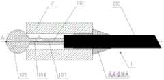
附图中的标记为:1-单模光纤,101-涂覆层,102-包层,103-纤芯,104-扩芯端,105-凸球状微透镜,2-玻璃管。The marks in the drawings are: 1-single-mode optical fiber, 101-coating layer, 102-cladding layer, 103-fiber core, 104-expanded core end, 105-convex spherical microlens, 2-glass tube.
实施方式Implementation
为了使本发明所解决的技术问题、技术方案及有益效果更加清楚明白,以下结合实施例,对本发明进行进一步详细说明。应当理解,此处所描述的具体实施例仅仅用以解释本发明,并不用于限定本发明。In order to make the technical problems, technical solutions and beneficial effects solved by the present invention clearer, the present invention will be further described in detail below in conjunction with the embodiments. It should be understood that the specific embodiments described here are only used to explain the present invention, and are not intended to limit the present invention.
实施例Example
请参阅图1,一种单模光纤扩芯一体式准直器,包括单模光纤1和玻璃管2,单模光纤1从外至内依次设置有涂覆层101、包层102和纤芯103,单模光纤1一端部分裸露包层102,纤芯103末端设置有扩芯端104,以提升光纤MFD大小,使其输出光得到扩束,扩芯端104为锥台体,扩芯端104小端直径与纤芯103直径相等,扩芯端104大端设置有凸球状微透镜105,纤芯103、扩芯端104、凸球状微透镜105一体化且同轴,扩芯端104由纤芯103扩芯处理而成,凸球状微透镜105由扩芯端104大端烧球处理而成,凸球状微透镜105的镜面曲率的焦距为1.2mm,凸球状微透镜105外顶点A至扩芯端104变形点B的长度与凸球状微透镜105的镜面曲率的焦距相等,确保输出准直光斑,且扩芯端104大端直径大于纤芯103的直径,使凸球状微透镜105输出的光束具有光斑直径大、光轴偏角小的特点,因此可承受的功率大于单模光纤1输出端的功率,即大于传统准直器的承受功率,规避了熔接扩束光纤引起的损耗发热风险,同时解决了短工作距离和光轴偏角不敏感特性,玻璃管2套于裸露的包层102上且涂覆层101部分伸于玻璃管2内,涂覆层101伸于玻璃管2内的距离为3~5 mm,玻璃管2一端紧靠凸球状微透镜105,另一端与涂覆层101利用抗高温胶水胶接密封。Please refer to Figure 1, an integrated collimator for single-mode fiber core expansion, including a single-mode fiber 1 and a
其制备方法包括以下步骤:Its preparation method comprises the following steps:
1)选取125um单模光纤,剥除单模光纤1一端的涂覆层101,露出包层102;1) Select a 125um single-mode fiber, strip off the
2)采用氢氧火头对纤芯103末端进行加热扩芯处理,形成锥台体的扩芯段104;2) Using a hydrogen-oxygen burner to heat and expand the end of the
3)调整烧球机光纤固定位置与三电极位置,设置放电强度和放电时间参数,放电强度220V,放电时间4秒,对扩芯段104的末端一次性熔烧成凸球状微透镜105,使凸球状微透镜105的中心轴与纤芯103、扩芯段104的中心轴重合,使凸球状微透镜105外顶点A至扩芯端104变形点B的长度与凸球状微透镜105的镜面曲率的焦距相等,凸球状微透镜105的镜面曲率的焦距控制在1.2~1.5mm,本实施例为1.2mm;3) Adjust the fixed position of the optical fiber and the position of the three electrodes of the ball burning machine, set the discharge intensity and discharge time parameters, the discharge intensity is 220V, and the discharge time is 4 seconds. The end of the expanded
4)使用玻璃管2套于裸露的包层102上且涂覆层101部分伸于玻璃管2内,涂覆层101伸于玻璃管2中的距离控制在3~5 mm,使玻璃管2一端紧靠凸球状微透镜105,另一端与涂覆层101利用抗高温胶水封装保护处理,即得单模光纤扩芯一体式准直器。4) Use the
经测试,耦合效率提升30%以上。After testing, the coupling efficiency has increased by more than 30%.
实施例Example
本实施例与实施例1基本相同,不同之处在于本实施例中凸球状微透镜105的镜面曲率的焦距为1.5mm。This embodiment is basically the same as Embodiment 1, except that the focal length of the curvature of the mirror surface of the convex
经测试,耦合效率提升30%以上。After testing, the coupling efficiency has increased by more than 30%.
尽管已经示出和描述了本发明的实施例,对于本领域的普通技术人员而言,可以理解在不脱离本发明的原理和精神的情况下可以对这些实施例进行多种变化、修改、替换和变型,本发明的范围由所附权利要求及其等同物限定。Although the embodiments of the present invention have been shown and described, those skilled in the art can understand that various changes, modifications and substitutions can be made to these embodiments without departing from the principle and spirit of the present invention. and modifications, the scope of the invention is defined by the appended claims and their equivalents.
Claims (9)
Priority Applications (1)
| Application Number | Priority Date | Filing Date | Title |
|---|---|---|---|
| CN202310241496.0ACN116299871A (en) | 2023-03-14 | 2023-03-14 | A single-mode optical fiber core expansion integrated collimator and preparation method |
Applications Claiming Priority (1)
| Application Number | Priority Date | Filing Date | Title |
|---|---|---|---|
| CN202310241496.0ACN116299871A (en) | 2023-03-14 | 2023-03-14 | A single-mode optical fiber core expansion integrated collimator and preparation method |
Publications (1)
| Publication Number | Publication Date |
|---|---|
| CN116299871Atrue CN116299871A (en) | 2023-06-23 |
Family
ID=86812726
Family Applications (1)
| Application Number | Title | Priority Date | Filing Date |
|---|---|---|---|
| CN202310241496.0APendingCN116299871A (en) | 2023-03-14 | 2023-03-14 | A single-mode optical fiber core expansion integrated collimator and preparation method |
Country Status (1)
| Country | Link |
|---|---|
| CN (1) | CN116299871A (en) |
Citations (5)
| Publication number | Priority date | Publication date | Assignee | Title |
|---|---|---|---|---|
| CN101995602A (en)* | 2010-12-03 | 2011-03-30 | 蒋菊生 | Expanded core fiber |
| CN102253457A (en)* | 2011-08-08 | 2011-11-23 | 上海理工大学 | Hot core expansion optical fiber collimator |
| CN104656194A (en)* | 2015-02-05 | 2015-05-27 | 深圳朗光科技有限公司 | Collimator and on-line polarizer comprising same |
| CN108761665A (en)* | 2018-03-22 | 2018-11-06 | 中国科学院上海光学精密机械研究所 | The method for improving multi-core optical fiber coupling efficiency |
| CN211698277U (en)* | 2020-03-13 | 2020-10-16 | 光越科技(深圳)有限公司 | Optical fiber collimator |
- 2023
- 2023-03-14CNCN202310241496.0Apatent/CN116299871A/enactivePending
Patent Citations (5)
| Publication number | Priority date | Publication date | Assignee | Title |
|---|---|---|---|---|
| CN101995602A (en)* | 2010-12-03 | 2011-03-30 | 蒋菊生 | Expanded core fiber |
| CN102253457A (en)* | 2011-08-08 | 2011-11-23 | 上海理工大学 | Hot core expansion optical fiber collimator |
| CN104656194A (en)* | 2015-02-05 | 2015-05-27 | 深圳朗光科技有限公司 | Collimator and on-line polarizer comprising same |
| CN108761665A (en)* | 2018-03-22 | 2018-11-06 | 中国科学院上海光学精密机械研究所 | The method for improving multi-core optical fiber coupling efficiency |
| CN211698277U (en)* | 2020-03-13 | 2020-10-16 | 光越科技(深圳)有限公司 | Optical fiber collimator |
Similar Documents
| Publication | Publication Date | Title |
|---|---|---|
| US8509577B2 (en) | Fiberoptic device with long focal length gradient-index or grin fiber lens | |
| CN103728696B (en) | A kind of 1 �� N fiber coupler | |
| CN102681109B (en) | Large-caliber light beam coupler | |
| CN101852894B (en) | Coupling method for suspended-core optical fibers | |
| CN102147499B (en) | Optical fiber fusion tapering method using high-frequency pulsed carbon dioxide laser as heat source | |
| JPH04211205A (en) | Fiber optic coupler and manufacture thereof | |
| CN102253457A (en) | Hot core expansion optical fiber collimator | |
| US20160124168A1 (en) | Pigtailed laser device based on spherical lens coupling | |
| CN116449496A (en) | Solid optical fiber and hollow optical fiber coupling device | |
| CN2748933Y (en) | N*1 optical fiber beam combiner | |
| CN108761646A (en) | A kind of optical fiber pigtail | |
| CN104656194A (en) | Collimator and on-line polarizer comprising same | |
| CN118732170A (en) | Method and device for improving solid core optical fiber-hollow core optical fiber coupling efficiency | |
| CN103823277A (en) | Optical fiber connector | |
| CN205038369U (en) | Novel high power optical collimator structure | |
| CN116299871A (en) | A single-mode optical fiber core expansion integrated collimator and preparation method | |
| CN208654360U (en) | A kind of optical fiber pigtail | |
| CN201413416Y (en) | Optical fiber LD coupling structure used for wave band of visible light | |
| CN103558663A (en) | S-shaped photonic crystal fiber taper sensor and preparing method thereof | |
| JP2007500870A (en) | Fiber with lens with small form factor and method for producing the same | |
| CN209028250U (en) | An all-fiber mode controller | |
| CN1508584A (en) | A coupling method of semiconductor laser and optical fiber and coupling device thereof | |
| CN1323304C (en) | Multi mould multi-optical fiber power coupler and its preparation method | |
| CN111965757A (en) | Multi-core fiber fan-in fan-out beam splitter based on direct alignment coupling of collimated beams | |
| CN203745677U (en) | Welding device of optical fiber end cap |
Legal Events
| Date | Code | Title | Description |
|---|---|---|---|
| PB01 | Publication | ||
| PB01 | Publication | ||
| SE01 | Entry into force of request for substantive examination | ||
| SE01 | Entry into force of request for substantive examination |