CN116299611A - Floating type electronic boundary pile capable of being charged wirelessly and monitoring method - Google Patents
Floating type electronic boundary pile capable of being charged wirelessly and monitoring methodDownload PDFInfo
- Publication number
- CN116299611A CN116299611ACN202310260073.3ACN202310260073ACN116299611ACN 116299611 ACN116299611 ACN 116299611ACN 202310260073 ACN202310260073 ACN 202310260073ACN 116299611 ACN116299611 ACN 116299611A
- Authority
- CN
- China
- Prior art keywords
- chip
- electrically connected
- wireless
- pin
- charging
- Prior art date
- Legal status (The legal status is an assumption and is not a legal conclusion. Google has not performed a legal analysis and makes no representation as to the accuracy of the status listed.)
- Granted
Links
Images


Classifications
- B—PERFORMING OPERATIONS; TRANSPORTING
- B63—SHIPS OR OTHER WATERBORNE VESSELS; RELATED EQUIPMENT
- B63B—SHIPS OR OTHER WATERBORNE VESSELS; EQUIPMENT FOR SHIPPING
- B63B22/00—Buoys
- G—PHYSICS
- G01—MEASURING; TESTING
- G01P—MEASURING LINEAR OR ANGULAR SPEED, ACCELERATION, DECELERATION, OR SHOCK; INDICATING PRESENCE, ABSENCE, OR DIRECTION, OF MOVEMENT
- G01P15/00—Measuring acceleration; Measuring deceleration; Measuring shock, i.e. sudden change of acceleration
- G01P15/14—Measuring acceleration; Measuring deceleration; Measuring shock, i.e. sudden change of acceleration by making use of gyroscopes
- G—PHYSICS
- G01—MEASURING; TESTING
- G01P—MEASURING LINEAR OR ANGULAR SPEED, ACCELERATION, DECELERATION, OR SHOCK; INDICATING PRESENCE, ABSENCE, OR DIRECTION, OF MOVEMENT
- G01P15/00—Measuring acceleration; Measuring deceleration; Measuring shock, i.e. sudden change of acceleration
- G01P15/18—Measuring acceleration; Measuring deceleration; Measuring shock, i.e. sudden change of acceleration in two or more dimensions
- G—PHYSICS
- G01—MEASURING; TESTING
- G01S—RADIO DIRECTION-FINDING; RADIO NAVIGATION; DETERMINING DISTANCE OR VELOCITY BY USE OF RADIO WAVES; LOCATING OR PRESENCE-DETECTING BY USE OF THE REFLECTION OR RERADIATION OF RADIO WAVES; ANALOGOUS ARRANGEMENTS USING OTHER WAVES
- G01S19/00—Satellite radio beacon positioning systems; Determining position, velocity or attitude using signals transmitted by such systems
- G01S19/01—Satellite radio beacon positioning systems transmitting time-stamped messages, e.g. GPS [Global Positioning System], GLONASS [Global Orbiting Navigation Satellite System] or GALILEO
- G01S19/13—Receivers
- G01S19/24—Acquisition or tracking or demodulation of signals transmitted by the system
- G01S19/25—Acquisition or tracking or demodulation of signals transmitted by the system involving aiding data received from a cooperating element, e.g. assisted GPS
- G01S19/256—Acquisition or tracking or demodulation of signals transmitted by the system involving aiding data received from a cooperating element, e.g. assisted GPS relating to timing, e.g. time of week, code phase, timing offset
- G—PHYSICS
- G01—MEASURING; TESTING
- G01S—RADIO DIRECTION-FINDING; RADIO NAVIGATION; DETERMINING DISTANCE OR VELOCITY BY USE OF RADIO WAVES; LOCATING OR PRESENCE-DETECTING BY USE OF THE REFLECTION OR RERADIATION OF RADIO WAVES; ANALOGOUS ARRANGEMENTS USING OTHER WAVES
- G01S19/00—Satellite radio beacon positioning systems; Determining position, velocity or attitude using signals transmitted by such systems
- G01S19/38—Determining a navigation solution using signals transmitted by a satellite radio beacon positioning system
- G01S19/39—Determining a navigation solution using signals transmitted by a satellite radio beacon positioning system the satellite radio beacon positioning system transmitting time-stamped messages, e.g. GPS [Global Positioning System], GLONASS [Global Orbiting Navigation Satellite System] or GALILEO
- G01S19/42—Determining position
- G—PHYSICS
- G01—MEASURING; TESTING
- G01S—RADIO DIRECTION-FINDING; RADIO NAVIGATION; DETERMINING DISTANCE OR VELOCITY BY USE OF RADIO WAVES; LOCATING OR PRESENCE-DETECTING BY USE OF THE REFLECTION OR RERADIATION OF RADIO WAVES; ANALOGOUS ARRANGEMENTS USING OTHER WAVES
- G01S19/00—Satellite radio beacon positioning systems; Determining position, velocity or attitude using signals transmitted by such systems
- G01S19/38—Determining a navigation solution using signals transmitted by a satellite radio beacon positioning system
- G01S19/39—Determining a navigation solution using signals transmitted by a satellite radio beacon positioning system the satellite radio beacon positioning system transmitting time-stamped messages, e.g. GPS [Global Positioning System], GLONASS [Global Orbiting Navigation Satellite System] or GALILEO
- G01S19/53—Determining attitude
- H—ELECTRICITY
- H02—GENERATION; CONVERSION OR DISTRIBUTION OF ELECTRIC POWER
- H02J—CIRCUIT ARRANGEMENTS OR SYSTEMS FOR SUPPLYING OR DISTRIBUTING ELECTRIC POWER; SYSTEMS FOR STORING ELECTRIC ENERGY
- H02J50/00—Circuit arrangements or systems for wireless supply or distribution of electric power
- H02J50/10—Circuit arrangements or systems for wireless supply or distribution of electric power using inductive coupling
- H—ELECTRICITY
- H04—ELECTRIC COMMUNICATION TECHNIQUE
- H04L—TRANSMISSION OF DIGITAL INFORMATION, e.g. TELEGRAPHIC COMMUNICATION
- H04L67/00—Network arrangements or protocols for supporting network services or applications
- H04L67/01—Protocols
- H04L67/12—Protocols specially adapted for proprietary or special-purpose networking environments, e.g. medical networks, sensor networks, networks in vehicles or remote metering networks
- H04L67/125—Protocols specially adapted for proprietary or special-purpose networking environments, e.g. medical networks, sensor networks, networks in vehicles or remote metering networks involving control of end-device applications over a network
- H—ELECTRICITY
- H04—ELECTRIC COMMUNICATION TECHNIQUE
- H04W—WIRELESS COMMUNICATION NETWORKS
- H04W4/00—Services specially adapted for wireless communication networks; Facilities therefor
- H04W4/02—Services making use of location information
- H04W4/021—Services related to particular areas, e.g. point of interest [POI] services, venue services or geofences
- Y—GENERAL TAGGING OF NEW TECHNOLOGICAL DEVELOPMENTS; GENERAL TAGGING OF CROSS-SECTIONAL TECHNOLOGIES SPANNING OVER SEVERAL SECTIONS OF THE IPC; TECHNICAL SUBJECTS COVERED BY FORMER USPC CROSS-REFERENCE ART COLLECTIONS [XRACs] AND DIGESTS
- Y02—TECHNOLOGIES OR APPLICATIONS FOR MITIGATION OR ADAPTATION AGAINST CLIMATE CHANGE
- Y02T—CLIMATE CHANGE MITIGATION TECHNOLOGIES RELATED TO TRANSPORTATION
- Y02T10/00—Road transport of goods or passengers
- Y02T10/60—Other road transportation technologies with climate change mitigation effect
- Y02T10/70—Energy storage systems for electromobility, e.g. batteries
Landscapes
- Engineering & Computer Science (AREA)
- Radar, Positioning & Navigation (AREA)
- Remote Sensing (AREA)
- Computer Networks & Wireless Communication (AREA)
- General Physics & Mathematics (AREA)
- Physics & Mathematics (AREA)
- Signal Processing (AREA)
- Computing Systems (AREA)
- Medical Informatics (AREA)
- General Health & Medical Sciences (AREA)
- Health & Medical Sciences (AREA)
- Power Engineering (AREA)
- Chemical & Material Sciences (AREA)
- Combustion & Propulsion (AREA)
- Mechanical Engineering (AREA)
- Ocean & Marine Engineering (AREA)
- Charge And Discharge Circuits For Batteries Or The Like (AREA)
Abstract
Translated fromChinese
Description
Translated fromChinese技术领域technical field
本发明涉及电子界桩技术领域,尤其涉及一种无线充电的漂浮式电子界桩及监测方法。The invention relates to the technical field of electronic boundary posts, in particular to a wireless charging floating electronic boundary post and a monitoring method.
背景技术Background technique
界桩是指作为地界标志的指示物,用来标示不同属性或者不同权利范围的土地周围界址,界桩根据结构可以分为传统界桩和电子界桩,传统界桩包括水泥界桩、塑料界桩或者金属界桩,表面镌刻文字以便于识别;电子界桩是近年来发展起来的确权装置,使用现代信息技术,采集和传输定位信息、报警信息等。传统的界桩依赖管理人员定期巡视,容易遭到破坏或者人为移动,对确权带来不利影响。电子界桩较传统界桩具有明显的优势,能够感知周围环境,避免人为搬运或者破坏,已得到广泛的应用。作为电子产品,电子界桩需要内置电源,如在户外长期运行,还需要定期进行充电,为了便于充电或外界太阳能发电装置,界桩表面往往要预留充电接口,不仅降低了电子界桩的可靠性,而且容易损坏,不适用于水体等潮湿的环境。Boundary stakes refer to indicators as land boundary markers, which are used to mark the boundaries around the land with different attributes or different scopes of rights. Boundary stakes can be divided into traditional boundary stakes and electronic boundary stakes according to their structure. Traditional boundary stakes include cement boundary stakes, plastic boundary stakes or metal boundary stakes. Engraved text for easy identification; electronic boundary post is a right confirmation device developed in recent years, using modern information technology to collect and transmit positioning information, alarm information, etc. Traditional boundary posts rely on regular inspections by managers, and are easily damaged or moved by humans, which will have an adverse effect on the confirmation of rights. Compared with traditional boundary posts, electronic boundary posts have obvious advantages. They can sense the surrounding environment and avoid human handling or damage, and have been widely used. As an electronic product, the electronic boundary post needs a built-in power supply. If it is used outdoors for a long time, it needs to be charged regularly. In order to facilitate charging or external solar power generation devices, charging ports are often reserved on the surface of the boundary post, which not only reduces the reliability of the electronic boundary post, but also Easily damaged, not suitable for wet environments such as water bodies.
中国发明专利CN110867054A公开了一种智能电子界桩监测系统,该方案通过充电电路与向电子界桩充电,仍采用了充电接口方式,显然不适用于潮湿且液面经常发生变化的水体环境使用,而且方案本身采用被动工作方式,需要巡查人员激活RFID才能工作,其他时间不主动监测,无法及时感知界桩位置的变化情况。因此,针对现有电子界桩普遍存在外置充电接口、不适用于水体环境、被动监测等缺点,研究一种无暴露接口、可持续运行,并可应用于水域潮湿环境的电子界桩,具有重要意义。Chinese invention patent CN110867054A discloses an intelligent electronic boundary post monitoring system. This solution uses a charging circuit to charge the electronic boundary post, and still uses a charging interface, which is obviously not suitable for use in wet water environments where the liquid level often changes, and the solution It adopts a passive working method, which requires inspectors to activate RFID to work. It does not actively monitor at other times, and cannot perceive changes in the position of boundary pillars in a timely manner. Therefore, it is of great significance to study an electronic boundary post that has no exposed interface, sustainable operation, and can be applied to the humid environment of waters, in view of the shortcomings of existing electronic boundary posts, such as external charging interface, unsuitable for water environment, and passive monitoring. .
发明内容Contents of the invention
有鉴于此,本发明提出了一种无外置接口、具有主动环境监测功能、无线充电的漂浮式电子界桩及监测方法。In view of this, the present invention proposes a floating electronic boundary post with no external interface, active environment monitoring function and wireless charging and a monitoring method.
本发明的技术方案是这样实现的:一方面,本发明提供了一种无线充电的漂浮式电子界桩,包括:The technical solution of the present invention is achieved as follows: On the one hand, the present invention provides a wireless charging floating electronic boundary post, including:
本体,内部中空;Body, hollow inside;
数据采集单元,设置在本体内,用于获取界桩的位置信号和加速度信号;The data acquisition unit is arranged in the body and is used to acquire the position signal and acceleration signal of the boundary post;
通信单元,与数据采集单元通信连接,用于与远程的云端接收平台远程通信;The communication unit is connected to the data acquisition unit for remote communication with the remote cloud receiving platform;
电源单元,设置在本体内,用于向数据采集单元和通信单元供电;The power supply unit is arranged in the body and is used to supply power to the data acquisition unit and the communication unit;
无线充电单元,设置在本体内,用于向电源单元非接触式无线充电;The wireless charging unit is arranged in the body and is used for non-contact wireless charging to the power supply unit;
其中,所述本体跟随液面的高度浮动;无线充电单元还与外置的便携式充电站进行无线能量传输。Wherein, the body floats with the height of the liquid surface; the wireless charging unit also performs wireless energy transmission with an external portable charging station.
在以上技术方案的基础上,优选的,所述本体包括若干顺次嵌套设置的支撑体和浮筒;若干支撑体和浮筒内部中空,若干支撑体远离水体底部的一端设置有窗口;最外侧的支撑体非开设窗口的端部固设在水体底部,与该最外侧支撑体相邻的支撑体穿置在窗口的内表面内且与最外侧的支撑体滑动连接;浮筒嵌设在最内侧的支撑体的窗口内,并与最内侧支撑体滑动连接;非固定状态的若干支撑体和浮筒跟随液位的变化上升或者下降;所述数据采集单元、通信单元、电源单元和无线充电单元均设置在浮筒伸出水体的一端。On the basis of the above technical solutions, preferably, the body includes several support bodies and buoys nested in sequence; several support bodies and buoys are hollow inside, and a window is provided at one end of several support bodies away from the bottom of the water body; the outermost The end of the support without the window is fixed at the bottom of the water body, and the support adjacent to the outermost support is inserted into the inner surface of the window and slidably connected with the outermost support; the buoy is embedded in the innermost In the window of the support body, and slidingly connected with the innermost support body; several support bodies and buoys in the non-fixed state rise or fall with the change of the liquid level; the data acquisition unit, communication unit, power supply unit and wireless charging unit are all set At the end of the buoy protruding from the body of water.
优选的,所述数据采集单元包括定位芯片U7、加速度传感器U8和MCU;MCU包括若干通信接口和通用输入输出接口;定位芯片U7的引脚1与+3.3V电源电性连接,定位芯片U7的引脚2接地,定位芯片U7的引脚3和引脚4分别与MCU的一个通信接口一一对应电性连接;加速度传感器U8的引脚13与+3.3V电源电性连接,加速度传感器U8的引脚18接地,加速度传感器U8的引脚23和引脚24分别与MCU的另一个通信接口一一对应电性连接,加速度传感器U8的引脚12与MCU的一个通用输入输出接口电性连接;所述定位芯片U7采用NEO-6M-SCH,加速度传感器U8采用MPU6050。Preferably, the data acquisition unit includes a positioning chip U7, an acceleration sensor U8 and an MCU; the MCU includes several communication interfaces and general input and output interfaces; the
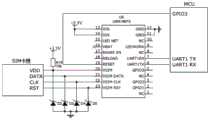
进一步优选的,所述通信单元包括无线传输芯片U6和SIM卡槽;无线传输芯片U6的引脚6和引脚7与MCU的一个通信接口一一对应电性连接,无线传输芯片U6的引脚11和引脚12接地,无线传输芯片U6的引脚13和引脚14与+3.3V电源电性连接,无线传输芯片U6的引脚19与MCU的一个通用输入输出接口电性连接,无线传输芯片U6的引脚20分别与SIM卡槽的VDD端、电阻R16的一端和第二稳压二极管D2的阴极电性连接,电阻R16的另一端与+3.3V电性连接;无线传输芯片U6的引脚21分别与SIM卡槽的DATA端和第三稳压二极管D3的阴极电性连接;无线传输芯片U6的引脚22分别与SIM卡槽的CLK端和第四稳压二极管D4的阴极电性连接;无线传输芯片U6的引脚23分别与SIM卡槽的RST端和第五稳压二极管D5的阴极电性连接,第二稳压二极管D2的阳极、第三稳压二极管D3的阳极、第四稳压二极管D4的阳极和第五稳压二极管D5的阳极均接地;无线传输芯片U6采用USR-NB75物联网通信芯片。Further preferably, the communication unit includes a wireless transmission chip U6 and a SIM card slot; the
更进一步优选的,所述电源单元包括蓄电池、降压芯片U4和升压芯片U5;降压芯片U4的输入端与蓄电池的正极电性连接,降压芯片U4的输出端输出+3.3V电源;升压芯片U5的输入端和使能端与蓄电池的正极电性连接,升压芯片U5的开关端与电感L4的一端电性连接,电感L4的另一端与升压芯片U5的输入端电性连接,升压芯片U5的输出端输出+5V电源;升压芯片U5的输出端还与电阻R18的一端电性连接,电阻R18的另一端分别与电阻R17的一端和升压芯片U5的反馈输入端电性连接,电阻R17的另一端接地;降压芯片U4选用LM1117-3.3V,升压芯片U5选用PS7516。More preferably, the power supply unit includes a battery, a step-down chip U4 and a boost chip U5; the input terminal of the step-down chip U4 is electrically connected to the positive pole of the battery, and the output terminal of the step-down chip U4 outputs +3.3V power; The input end and enable end of the boost chip U5 are electrically connected to the positive pole of the battery, the switch end of the boost chip U5 is electrically connected to one end of the inductor L4, and the other end of the inductor L4 is electrically connected to the input end of the boost chip U5. Connection, the output terminal of the boost chip U5 outputs +5V power supply; the output terminal of the boost chip U5 is also electrically connected to one end of the resistor R18, and the other end of the resistor R18 is respectively connected to one end of the resistor R17 and the feedback input of the boost chip U5 The terminals are electrically connected, and the other end of the resistor R17 is grounded; the step-down chip U4 uses LM1117-3.3V, and the step-up chip U5 uses PS7516.
再进一步优选的,所述无线充电单元包括无线发射芯片U1、无线接收芯片U2和充电芯片U3;无线发射芯片U1的输入端与外置的便携式充电站电性连接;无线发射芯片U1的输出端与第一线圈L1电性连接,第一线圈L1螺旋形卷绕并抵持在浮筒的外表面,用于无线功率发射;无线接收芯片U2的输入端与第二线圈L2电性连接,第二线圈L2螺旋形卷绕并设置在浮筒内,并与第一线圈L1相对间隔设置,用于无线接收功率;无线接收芯片U2的输出端与充电芯片U3的输入端电性连接,充电芯片U3的充电状态输出端分别与第三LED的阳极和第四LED4的阴极电性连接,第三LED的阴极接地,第四LED的阳极与充电芯片U3的输入端电性连接;充电芯片U3的输出端与蓄电池的正极电性连接,充电芯片U3用于向蓄电池充电;所述无线发射芯片U1采用IP6826;所述无线接收芯片U2采用NU1680;充电芯片U3采用MCP73831T。Still further preferably, the wireless charging unit includes a wireless transmitting chip U1, a wireless receiving chip U2 and a charging chip U3; the input terminal of the wireless transmitting chip U1 is electrically connected to an external portable charging station; the output terminal of the wireless transmitting chip U1 Electrically connected with the first coil L1, the first coil L1 is helically wound and held against the outer surface of the buoy for wireless power transmission; the input end of the wireless receiving chip U2 is electrically connected with the second coil L2, the second The coil L2 is spirally wound and arranged in the buoy, and is set at a distance from the first coil L1 for wireless power reception; the output end of the wireless receiving chip U2 is electrically connected to the input end of the charging chip U3, and the charging chip U3 The charging state output terminal is electrically connected to the anode of the third LED and the cathode of the fourth LED4 respectively, the cathode of the third LED is grounded, and the anode of the fourth LED is electrically connected to the input terminal of the charging chip U3; the output terminal of the charging chip U3 The charging chip U3 is used to charge the battery; the wireless transmitting chip U1 adopts IP6826; the wireless receiving chip U2 adopts NU1680; the charging chip U3 adopts MCP73831T.
更进一步的优选的,所述浮筒伸出窗口的表面设置有粗糙段,第一线圈L1可拆卸式的设置在粗糙段处的浮筒表面;浮筒内部还设置有中空的密封盒,数据采集单元、通信单元、电源单元和无线充电单元均设置在密封盒内;密封盒与浮筒的内表面间隔设置,密封盒与浮筒内表面之间设置有缓冲层。More preferably, the surface of the buoy extending out of the window is provided with a rough section, and the first coil L1 is detachably arranged on the surface of the buoy at the rough section; the inside of the buoy is also provided with a hollow sealed box, a data acquisition unit, The communication unit, the power supply unit and the wireless charging unit are all arranged in the sealed box; the sealed box is arranged at intervals from the inner surface of the buoy, and a buffer layer is arranged between the sealed box and the inner surface of the buoy.
优选的,所述若干支撑体上均设置有排水口,排水口设置在若干支撑体靠近水体底部的一端。Preferably, the plurality of supports are all provided with drainage outlets, and the drainage outlets are arranged at one end of the plurality of supports near the bottom of the water body.
另一方面,本发明还提供了一种无线充电的漂浮式电子界桩的监测方法,包括如下步骤:On the other hand, the present invention also provides a wireless charging floating electronic boundary post monitoring method, including the following steps:
配置上述的无线充电的漂浮式电子界桩;The above-mentioned floating electronic boundary post with wireless charging;
无线充电的漂浮式电子界桩选择性的进入定时工作模式或者报警中断模式;The wireless charging floating electronic boundary post selectively enters the timing work mode or the alarm interruption mode;
定时工作模式时,数据采集单元和通信单元按预设的时间间隔定时启动,并获取当前界桩的位置信号、加速度信号和实时时间,从而确认界桩的当前位置和姿态;位置信号、加速度信号和实时时间经通信单元封装为定时数据包后发送到远程的云端接收平台;定时数据包发送成功后,进入下一个定时工作循环计时,如果达到预设的发送时间阈值,定时数据包仍未发送成功,则同样进入下一个定时工作循环计时,但是会由数据采集单元在预先建立的连续失败传输记录中进行累加存储;In the timing working mode, the data acquisition unit and the communication unit start regularly according to the preset time interval, and obtain the position signal, acceleration signal and real-time time of the current boundary post, so as to confirm the current position and attitude of the boundary post; the position signal, acceleration signal and real-time The time is encapsulated into a timing data packet by the communication unit and sent to the remote cloud receiving platform; after the timing data packet is successfully sent, it will enter the next timing working cycle timing. If the preset sending time threshold is reached, the timing data packet has not been sent successfully. Then it will also enter the next timing working cycle timing, but it will be accumulated and stored in the pre-established continuous failure transmission records by the data acquisition unit;
报警中断模式时,数据采集单元的加速度传感器U8连续的输入信号触发并唤醒MCU,MCU对加速度传感器U8的输入进一步判断,确认是否为有效的震动/倾斜信号;如加速度传感器U8输入的信号确认为有效的震动/倾斜信号,数据采集单元获取当前界桩的位置信号和实时时间,位置信号、震动/倾斜信号和实时时间经通信单元封装为数据包后发送到远程的云端接收平台;如加速度传感器U8输入的信号经确认不是有效的震动/倾斜信号,则MCU会等待一段时间,继续接收来自加速度传感器U8的输入信号,直到有可靠的震动/倾斜信号输入MCU,数据采集单元获取当前界桩的位置信号和实时时间,位置信号、震动/倾斜信号和实时时间经通信单元封装为报警数据包后发送到远程的云端接收平台;如果加速度传感器U8超过预设的响应时间后仍未返回有效的输入信号,或者通信单元达到预设的发送时间阈值,报警数据包仍未发送成功的,则进行中断返回;但是会由数据采集单元在预先建立的中断失败传输记录中进行累加存储;In the alarm interrupt mode, the continuous input signal of the acceleration sensor U8 of the data acquisition unit triggers and wakes up the MCU, and the MCU further judges the input of the acceleration sensor U8 to confirm whether it is a valid vibration/tilt signal; if the signal input by the acceleration sensor U8 is confirmed as For effective vibration/tilt signals, the data acquisition unit obtains the position signal and real-time time of the current boundary post. The position signal, vibration/tilt signal and real-time time are encapsulated into data packets by the communication unit and sent to the remote cloud receiving platform; such as the acceleration sensor U8 It is confirmed that the input signal is not a valid vibration/tilt signal, then the MCU will wait for a period of time and continue to receive the input signal from the acceleration sensor U8 until a reliable vibration/tilt signal is input to the MCU, and the data acquisition unit obtains the position signal of the current boundary post and real-time time, position signal, vibration/tilt signal and real-time time are sent to the remote cloud receiving platform after being encapsulated into an alarm data packet by the communication unit; if the acceleration sensor U8 has not returned a valid input signal after exceeding the preset response time, Or if the communication unit reaches the preset sending time threshold and the alarm data packet is still not sent successfully, the interrupt will be returned; however, the data acquisition unit will accumulate and store in the pre-established interrupt failure transmission record;
当定时工作模式时,连续N个周期均有定时数据包连续失败传输记录;或者当报警中断模式时,连续M个中断均有报警数据包中断失败传输记录的,云端接收平台发出界桩通信异常警告信息,提示管理人员现场排查;N、M均为整数;In the timing working mode, there are consecutive failed transmission records of timing data packets for N consecutive cycles; or in the alarm interrupt mode, if there are alarm data packet interruption and failed transmission records for M consecutive interruptions, the cloud receiving platform will issue a boundary post communication abnormal warning information, prompting the management personnel to conduct on-site investigation; N and M are both integers;
数据采集单元的MCU还获取电源单元的蓄电池充电电压,并向云端接收平台发送充电请求。The MCU of the data acquisition unit also obtains the battery charging voltage of the power supply unit, and sends a charging request to the cloud receiving platform.
优选的,所述在报警中断模式时,如果加速度传感器U8超过预设的响应时间后仍未返回有效的输入信号,或者通信单元达到预设的发送时间阈值,报警数据包仍未发送成功的,当数据采集单元在预先建立的中断失败传输记录中进行连续累加存储达到M次时,无线充电的漂浮式电子界桩不再进入报警中断模式,而是保持在定时工作模式下工作,判断当前界桩在定时工作模式下是否存在定时数据包的连续失败传输记录的累加现象,并由数据采集单元进行记录保存。Preferably, in the alarm interruption mode, if the acceleration sensor U8 has not returned a valid input signal after exceeding the preset response time, or the communication unit reaches the preset sending time threshold, and the alarm data packet has not been sent successfully, When the data acquisition unit performs continuous accumulative storage for M times in the pre-established interruption failure transmission record, the wireless charging floating electronic boundary post will no longer enter the alarm interruption mode, but will keep working in the timing work mode, judging that the current boundary post is in Whether there is an accumulation phenomenon of continuous failure transmission records of timing data packets in the timing working mode, and the records are saved by the data acquisition unit.
本发明提供的一种无线充电的漂浮式电子界桩,相对于现有技术,具有以下有益效果:Compared with the prior art, a wireless charging floating electronic boundary post provided by the present invention has the following beneficial effects:
(1)本方案取消了外置的接口,接口部位不容易被损坏,而是通过非接触式的无线充电方式充电,在户外能够可靠的运行;(1) This solution cancels the external interface, the interface part is not easy to be damaged, but it is charged by non-contact wireless charging, and it can operate reliably outdoors;
(2)本体能够适应水位的高度而变化,设备内置于本体内部,并隔水密封,使本方案的电子界桩尤其适用于潮湿的水体环境;(2) The body can adapt to changes in the height of the water level, and the equipment is built into the body and sealed against water, making the electronic boundary post of this solution especially suitable for wet water environments;
(3)采用定时工作模式与报警工作模式相结合的方式,节省能源开销并能主动监控界桩的姿态和位置变化,将水体用界桩的被动监测改为主动监测方式,克服人工定期巡查导致的不便。(3) The combination of timing work mode and alarm work mode is adopted to save energy costs and actively monitor the posture and position changes of boundary posts, and change the passive monitoring of water body boundary posts to active monitoring to overcome the inconvenience caused by manual regular inspections .
附图说明Description of drawings
为了更清楚地说明本发明实施例或现有技术中的技术方案,下面将对实施例或现有技术描述中所需要使用的附图作简单地介绍,显而易见地,下面描述中的附图仅仅是本发明的一些实施例,对于本领域普通技术人员来讲,在不付出创造性劳动的前提下,还可以根据这些附图获得其他的附图。In order to more clearly illustrate the technical solutions in the embodiments of the present invention or the prior art, the following will briefly introduce the drawings that need to be used in the description of the embodiments or the prior art. Obviously, the accompanying drawings in the following description are only These are some embodiments of the present invention. Those skilled in the art can also obtain other drawings based on these drawings without creative work.
图1为本发明一种无线充电的漂浮式电子界桩的前视图;Fig. 1 is a front view of a wireless charging floating electronic boundary post of the present invention;
图2为本发明一种无线充电的漂浮式电子界桩的半剖前视图;Fig. 2 is a half-section front view of a wireless charging floating electronic boundary post of the present invention;
图3为本发明一种无线充电的漂浮式电子界桩的浮筒的半剖前视图;Fig. 3 is a half-cut front view of the buoy of a wireless charging floating electronic boundary post of the present invention;
图4为本发明一种无线充电的漂浮式电子界桩的充电状态示意图;Fig. 4 is a schematic diagram of a charging state of a wireless charging floating electronic boundary post of the present invention;
图5为本发明一种无线充电的漂浮式电子界桩的结构框图;Fig. 5 is a structural block diagram of a wireless charging floating electronic boundary post of the present invention;
图6为本发明一种无线充电的漂浮式电子界桩的无线充电单元的部分接线图;Fig. 6 is a partial wiring diagram of a wireless charging unit of a wireless charging floating electronic boundary post of the present invention;
图7为本发明一种无线充电的漂浮式电子界桩的无线充电单元的另一部分接线图;Fig. 7 is a wiring diagram of another part of the wireless charging unit of a wireless charging floating electronic boundary post of the present invention;
图8为本发明一种无线充电的漂浮式电子界桩的电源单元的接线图;Fig. 8 is a wiring diagram of a power supply unit of a wireless charging floating electronic boundary post of the present invention;
图9为本发明一种无线充电的漂浮式电子界桩的通信单元的接线图;Fig. 9 is a wiring diagram of a communication unit of a wireless charging floating electronic boundary post of the present invention;
图10为本发明一种无线充电的漂浮式电子界桩的数据采集单元的部分接线图;Fig. 10 is a partial wiring diagram of the data acquisition unit of a wireless charging floating electronic boundary post of the present invention;
图11为本发明一种无线充电的漂浮式电子界桩的数据采集单元的一部分接线图;Fig. 11 is a part of the wiring diagram of the data acquisition unit of a wireless charging floating electronic boundary post in the present invention;
图12为本发明一种无线充电的漂浮式电子界桩的监测方法的定时工作模式的流程图;Fig. 12 is a flow chart of the timing working mode of a monitoring method of a wireless charging floating electronic boundary post in the present invention;
图13为本发明一种无线充电的漂浮式电子界桩的监测方法的报警中断模式的流程图。Fig. 13 is a flowchart of an alarm interruption mode of a monitoring method of a wireless charging floating electronic boundary post according to the present invention.
附图标记:1、本体;2、数据采集单元;3、通信单元;4、电源单元;5、无线充电单元;11、支撑体;12、浮筒;100、窗口;200、粗糙段;120、密封盒;300、缓冲层;400、排水口;111、第一支撑体;112、第二支撑体;113、第三支撑体。Reference signs: 1, body; 2, data acquisition unit; 3, communication unit; 4, power supply unit; 5, wireless charging unit; 11, support body; 12, buoy; 100, window; 200, rough section; 120, Sealing box; 300, buffer layer; 400, drain port; 111, first support body; 112, second support body; 113, third support body.
具体实施方式Detailed ways
下面将结合本发明实施方式,对本发明实施方式中的技术方案进行清楚、完整地描述,显然,所描述的实施方式仅仅是本发明一部分实施方式,而不是全部的实施方式。基于本发明中的实施方式,本领域普通技术人员在没有做出创造性劳动前提下所获得的所有其他实施方式,都属于本发明保护的范围。The following will clearly and completely describe the technical solutions in the embodiments of the present invention in conjunction with the embodiments of the present invention. Obviously, the described embodiments are only part of the embodiments of the present invention, not all of them. Based on the implementation manners in the present invention, all other implementation manners obtained by persons of ordinary skill in the art without making creative efforts belong to the scope of protection of the present invention.
如图1-图5所示,一方面,本发明提供了一种无线充电的漂浮式电子界桩,包括:As shown in Figures 1-5, on the one hand, the present invention provides a wireless charging floating electronic boundary post, including:
本体1,内部中空;本体1内部空间用于容纳数据采集单元2、通信单元3、电源单元4和部分无线充电单元5。The
数据采集单元2设置在本体1内,用于获取界桩的位置信号和加速度信号;The
通信单元3与数据采集单元2通信连接,用于与远程的云端接收平台通信;The
电源单元4设置在本体1内,用于向数据采集单元2和通信单元3供电;The
无线充电单元5设置在本体1内,用于向电源单元4非接触式无线充电;The
其中,本体1跟随液面的高度浮动;无线充电单元5还与外置的便携式充电站进行无线能量传输。无线充电单元5的接收部分位于本体1内部,当需要充电时,由管理人员携带外置的便携式充电站与无线充电单元5的发射部分进行连接,发射部分与接收部分进行无线能量传输即可,无线充电单元5的发射部分可以与便携式充电站整合为一体,在非充电状态时与本体1可拆卸式连接,在充电状态时与贴附或者固定在本体1的外表面上。由于没有采用外置的裸露接口,避免了人为损坏和在潮湿水体环境中故障或者短路的可能,提高了水体界桩的适用性和可靠性。Wherein, the
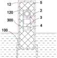
同样如图1和图5所示,为了适应水体液面高度的变化,本体1包括若干顺次嵌套设置的支撑体11和浮筒12;若干支撑体11和浮筒12内部中空,若干支撑体11远离水体底部的一端设置有窗口100;最外侧的支撑体11非开设窗口100的端部固设在水体底部,与该最外侧支撑体11相邻的支撑体11穿置在窗口100的内表面内且与最外侧的支撑体11滑动连接;浮筒12嵌设在最内侧的支撑体11的窗口100内,并与最内侧支撑体11滑动连接;非固定状态的若干支撑体11和浮筒12跟随液位的变化上升或者下降;数据采集单元2、通信单元3、电源单元4和无线充电单元5均设置在浮筒12伸出水体的一端。以图2和图3为例进行说明,图2中的支撑体11共有三个,以第一支撑体111、第二支撑体112和第三支撑体113进行区分;最外侧的第一支撑体111的一端与水体底部固定连接,第一支撑体111的另一端设置有窗口100;类似的,第二支撑体112嵌设在第一支撑体111的窗口100内,第三支撑体113嵌设在第二支撑体112的窗口100内,浮筒12则嵌设在第三支撑体113的窗口100内。若干支撑体11和浮筒12采用轻质可漂浮材料,且不妨碍电磁信号传输,如玻璃钢、PVC或者亚克力材料制成。为了更好的适应水位高度的大范围变化,若干支撑体11上均设置有排水口400,排水口400设置在若干支撑体11靠近水体底部的一端。当液位低于当前支撑体11的排水口400时,进入支撑体11内的水会从排水口排出,从而使当前支撑体11缩回相邻支撑体11的窗口100内,实现自适应液位调节。此处举例说明的图示采用了三个支撑体11,但是实际使用时的数量可以增加或者减少,图示内容不应视为对方案的支撑体11的数量限制。Also as shown in Figures 1 and 5, in order to adapt to changes in the liquid level of the water body, the
由图5结合图10和图11可知,数据采集单元2包括定位芯片U7、加速度传感器U8和MCU;MCU包括若干通信接口和通用输入输出接口;定位芯片U7的引脚1与+3.3V电源电性连接,定位芯片U7的引脚2接地,定位芯片U7的引脚3和引脚4分别与MCU的一个通信接口一一对应电性连接;加速度传感器U8的引脚13与+3.3V电源电性连接,加速度传感器U8的引脚18接地,加速度传感器U8的引脚23和引脚24分别与MCU的另一个通信接口一一对应电性连接,加速度传感器U8的引脚12与MCU的一个通用输入输出接口电性连接;定位芯片U7采用NEO-6M-SCH,加速度传感器U8采用MPU6050。定位芯片U7为GPS芯片,具有授时功能和全球定位功能,可以获取当前实时时间和界桩的当前位置信号,通过UART端口与MCU通信连接,除了采用文中提供的型号,还可以选择支持GNSS或者北斗系统的定位芯片,在此不再赘述。加速度传感器U8集成了三轴陀螺仪和三轴MEMS加速度计,内置16位精度的ADC,通过IIC串行总线与MCU通信连接,可以测量角度和加速度。当然测量界桩是否倾斜,还可以进一步使用测倾开关来实现,在此不再赘述。From Fig. 5 in conjunction with Fig. 10 and Fig. 11, it can be seen that the
如图5结合图9所示,通信单元3包括无线传输芯片U6和SIM卡槽;无线传输芯片U6的引脚6和引脚7与MCU的一个通信接口一一对应电性连接,无线传输芯片U6的引脚11和引脚12接地,无线传输芯片U6的引脚13和引脚14与+3.3V电源电性连接,无线传输芯片U6的引脚19与MCU的一个通用输入输出接口电性连接,无线传输芯片U6的引脚20分别与SIM卡槽的VDD端、电阻R16的一端和第二稳压二极管D2的阴极电性连接,电阻R16的另一端与+3.3V电性连接;无线传输芯片U6的引脚21分别与SIM卡槽的DATA端和第三稳压二极管D3的阴极电性连接;无线传输芯片U6的引脚22分别与SIM卡槽的CLK端和第四稳压二极管D4的阴极电性连接;无线传输芯片U6的引脚23分别与SIM卡槽的RST端和第五稳压二极管D5的阴极电性连接,第二稳压二极管D2的阳极、第三稳压二极管D3的阳极、第四稳压二极管D4的阳极和第五稳压二极管D5的阳极均接地;无线传输芯片U6采用USR-NB75物联网通信芯片。无线传输芯片U6支持4G/5G和NB-IOT物联网通信,可以任意选择,无线传输芯片U6本身通过UART端口与MCU通信连接;并通过预留的引脚20、引脚21、引脚22、和引脚23与SIM卡槽进行通信,第二稳压二极管D2、第三稳压二极管D3、第四稳压二极管D4和第五稳压二极管D5用于限压,无线传输芯片U6的引脚20还通过电阻R16做了上拉处理。As shown in Figure 5 in conjunction with Figure 9, the communication unit 3 includes a wireless transmission chip U6 and a SIM card slot; pins 6 and 7 of the wireless transmission chip U6 are electrically connected to a communication interface of the MCU one by one, and the wireless transmission chip Pin 11 and pin 12 of U6 are grounded, pin 13 and pin 14 of the wireless transmission chip U6 are electrically connected to the +3.3V power supply, and pin 19 of the wireless transmission chip U6 is electrically connected to a general input and output interface of the MCU connection, the pin 20 of the wireless transmission chip U6 is electrically connected to the VDD end of the SIM card slot, one end of the resistor R16, and the cathode of the second Zener diode D2, and the other end of the resistor R16 is electrically connected to +3.3V; The pins 21 of the transmission chip U6 are electrically connected to the DATA end of the SIM card slot and the cathode of the third Zener diode D3 respectively; the pins 22 of the wireless transmission chip U6 are respectively connected to the CLK end of the SIM card slot and the fourth Zener diode The cathode of D4 is electrically connected; the pin 23 of the wireless transmission chip U6 is respectively electrically connected with the RST end of the SIM card slot and the cathode of the fifth zener diode D5, the anode of the second zener diode D2, the third zener diode The anode of D3, the anode of the fourth zener diode D4 and the anode of the fifth zener diode D5 are all grounded; the wireless transmission chip U6 adopts the USR-NB75 IoT communication chip. The wireless transmission chip U6 supports 4G/5G and NB-IOT Internet of Things communication, which can be selected arbitrarily. The wireless transmission chip U6 itself communicates with the MCU through the UART port; and through the reserved
如图5结合图8所示,电源单元4包括蓄电池BAT、降压芯片U4和升压芯片U5;降压芯片U4的输入端与蓄电池的正极电性连接,降压芯片U4的输出端输出+3.3V电源,降压芯片U4的输入端和输出端的电容C19和C20具有滤波功能;升压芯片U5的输入端和使能端与蓄电池的正极电性连接,升压芯片U5的开关端与电感L4的一端电性连接,电感L4的另一端与升压芯片U5的输入端电性连接,升压芯片U5的输出端输出+5V电源;升压芯片U5的输出端还与电阻R18的一端电性连接,电阻R18的另一端分别与电阻R17的一端和升压芯片U5的反馈输入端电性连接,电阻R17的另一端接地;降压芯片U4选用LM1117-3.3V,升压芯片U5选用PS7516。蓄电池BAT可以采用锂电池,电压3.7-4.2V左右,为了提供通信单元3、数据采集单元2和无线充电单元5的工作电压,需要对蓄电池BAT的输出电压进行升压或者降压变换。升压芯片U5外围采用的电感L4决定了升压转换的开关频率和效率。电阻R18和电阻R17构成了分压电路,分压信号作为+5V电源输出的反馈信号送回升压芯片U5的反馈输入端,形成闭环反馈回路,使升压芯片U5根据反馈信号的大小来稳定+5V电源输出。As shown in Figure 5 in conjunction with Figure 8, the
如图3、图4、图5、图6和图7所示,无线充电单元5包括无线发射芯片U1、无线接收芯片U2和充电芯片U3;无线发射芯片U1的输入端与外置的便携式充电站电性连接;无线发射芯片U1的输出端与第一线圈L1电性连接,第一线圈L1螺旋形卷绕并抵持在浮筒12的外表面,用于无线功率发射;无线接收芯片U2的输入端与第二线圈L2电性连接,第二线圈L2螺旋形卷绕并设置在浮筒12内,并与第一线圈L1相对间隔设置,用于无线接收功率;无线接收芯片U2的输出端与充电芯片U3的输入端电性连接,充电芯片U3的充电状态输出端分别与第三LED的阳极和第四LED4的阴极电性连接,第三LED的阴极接地,第四LED的阳极与充电芯片U3的输入端电性连接;充电芯片U3的输出端与蓄电池的正极电性连接,充电芯片U3用于向蓄电池充电;所述无线发射芯片U1采用IP6826;无线接收芯片U2采用NU1680;充电芯片U3采用MCP73831T。图示的电路分为三个部分:功率发射部分、功率接收部分和蓄电池充电部分。功率发射部分对应了图4和图6,外置的便携式充电站的输入信号即图6中的VIN,可以是12V及以上直流信号,并联在LX1与LX2引脚之间的第一线圈L1是发射线圈,即图4中的虚线圆环部分,输出功率5W-15W;电容C5、C6、C7和C8作为去耦电容使用,第一稳压二极管D1阴极侧的电阻R7和R8分压后得到电压信号VDET,反馈输入至无线发射芯片U1的引脚30,输入电压反馈信号;而电阻R6、电阻C9、电阻R9和电容C10构成了解调输入的分支,获取的VDECODE信号输入无线发射芯片U1的引脚18,即内置解调器的输入端。另外,为了便于无线发射芯片U1与外置的便携式充电站连接,无线发射芯片U1的DP、DM、CC1和CC2引脚与扩展的USB TYPEC接口电性连接,第一发光二极管LED1和第二发光二极管LED2用于指示无线充电输出状态。功率接收部分对应了图3和图7的上半部分,第二线圈L2即图3中的实线圆环部分,无线接收芯片U2的电容C11、C12和C13起到去耦作用,无线接收芯片U2的引脚16和引脚5作为功率输入端,引脚6和引脚15是整流器输出,应尽可能远离其他信号电路,从而减小谐振环路。无线接收芯片U2的引脚8、引脚11、引脚9和引脚10分别与MCU的通用输入输出端口和IIC串行总线连接,实现中断、使能或者通信功能。无线接收芯片U2的引脚14输出VOUT1电压信号。但是VOUT1电压信号有可能无法直接被蓄电池BAT使用,故在图7下方增设了蓄电池充电部分,将VOUT1降为合适的充电电压供蓄电池BAT使用。此处采用了充电芯片U3,当进行蓄电池充电时,充电芯片U3的引脚1STAT输出低电平,第四发光二极管LED4点亮,第三发光二极管LED3熄灭;当没有对蓄电池进行充电时,充电芯片U3的引脚1STAT输出高电平,第四发光二极管LED4熄灭,第三发光二极管LED3点亮。进一步的,可以将蓄电池BAT的正极接入ADC通过测量蓄电池BAT的输出电压,判断蓄电池BAT的剩余容量。As shown in Fig. 3, Fig. 4, Fig. 5, Fig. 6 and Fig. 7, the
作为一种优选的实施方式,如图1和图3所示,浮筒12伸出窗口100的表面设置有粗糙段200,第一线圈L1可拆卸式的设置在粗糙段200处的浮筒12表面;浮筒12内部还设置有中空的密封盒120,数据采集单元2、通信单元3、电源单元4和无线充电单元5均设置在密封盒120内;密封盒120与浮筒12的内表面间隔设置,密封盒120与浮筒12内表面之间设置有缓冲层300。第一线圈L1可以采用磁吸的方式与粗糙段200处的浮筒12贴合,相应的浮筒12表面可以设置铁磁材料,粗糙段200能增大第一线圈L1与浮筒12表面的摩擦力,防止第一线圈L1滑落。当然第一线圈L1也可以采用柔性绑带的方式缠绕在浮筒12表面,柔性绑带上可进一步设置系绳或者魔术贴方便与浮筒12的拆卸。As a preferred embodiment, as shown in Figure 1 and Figure 3, the surface of the
另一方面,本发明还提供了一种无线充电的漂浮式电子界桩的监测方法,包括如下步骤:On the other hand, the present invention also provides a wireless charging floating electronic boundary post monitoring method, including the following steps:
配置上述的无线充电的漂浮式电子界桩;The above-mentioned floating electronic boundary post with wireless charging;
无线充电的漂浮式电子界桩选择性的进入定时工作模式或者报警中断模式;The wireless charging floating electronic boundary post selectively enters the timing work mode or the alarm interruption mode;
定时工作模式时,数据采集单元和通信单元按预设的时间间隔定时启动,并获取当前界桩的位置信号、加速度信号和实时时间,从而确认界桩的当前位置和姿态;位置信号、加速度信号和实时时间经通信单元封装为定时数据包后发送到远程的云端接收平台;定时数据包发送成功后,进入下一个定时工作循环计时,如果达到预设的发送时间阈值,定时数据包仍未发送成功,则同样进入下一个定时工作循环计时,但是会由数据采集单元在预先建立的连续失败传输记录中进行累加存储;In the timing working mode, the data acquisition unit and the communication unit start regularly according to the preset time interval, and obtain the position signal, acceleration signal and real-time time of the current boundary post, so as to confirm the current position and attitude of the boundary post; the position signal, acceleration signal and real-time The time is encapsulated into a timing data packet by the communication unit and sent to the remote cloud receiving platform; after the timing data packet is successfully sent, it will enter the next timing working cycle timing. If the preset sending time threshold is reached, the timing data packet has not been sent successfully. Then it will also enter the next timing working cycle timing, but it will be accumulated and stored in the pre-established continuous failure transmission records by the data acquisition unit;
报警中断模式时,数据采集单元的加速度传感器U8连续的输入信号触发并唤醒MCU,MCU对加速度传感器U8的输入进一步判断,确认是否为有效的震动/倾斜信号;如加速度传感器U8输入的信号确认为有效的震动/倾斜信号,数据采集单元获取当前界桩的位置信号和实时时间,位置信号、震动/倾斜信号和实时时间经通信单元封装为数据包后发送到远程的云端接收平台;如加速度传感器U8输入的信号经确认不是有效的震动/倾斜信号,则MCU会等待一段时间,继续接收来自加速度传感器U8的输入信号,直到有可靠的震动/倾斜信号输入MCU,数据采集单元获取当前界桩的位置信号和实时时间,位置信号、震动/倾斜信号和实时时间经通信单元封装为报警数据包后发送到远程的云端接收平台;如果加速度传感器U8超过预设的响应时间后仍未返回有效的输入信号,或者通信单元达到预设的发送时间阈值,报警数据包仍未发送成功的,则进行中断返回;但是会由数据采集单元在预先建立的中断失败传输记录中进行累加存储;In the alarm interrupt mode, the continuous input signal of the acceleration sensor U8 of the data acquisition unit triggers and wakes up the MCU, and the MCU further judges the input of the acceleration sensor U8 to confirm whether it is a valid vibration/tilt signal; if the signal input by the acceleration sensor U8 is confirmed as For effective vibration/tilt signals, the data acquisition unit obtains the position signal and real-time time of the current boundary post. The position signal, vibration/tilt signal and real-time time are encapsulated into data packets by the communication unit and sent to the remote cloud receiving platform; such as the acceleration sensor U8 It is confirmed that the input signal is not a valid vibration/tilt signal, then the MCU will wait for a period of time and continue to receive the input signal from the acceleration sensor U8 until a reliable vibration/tilt signal is input to the MCU, and the data acquisition unit obtains the position signal of the current boundary post and real-time time, position signal, vibration/tilt signal and real-time time are sent to the remote cloud receiving platform after being encapsulated into an alarm data packet by the communication unit; if the acceleration sensor U8 has not returned a valid input signal after exceeding the preset response time, Or if the communication unit reaches the preset sending time threshold and the alarm data packet is still not sent successfully, the interrupt will be returned; however, the data acquisition unit will accumulate and store in the pre-established interrupt failure transmission record;
当定时工作模式时,连续N个周期均有定时数据包连续失败传输记录;或者当报警中断模式时,连续M个中断均有报警数据包中断失败传输记录的,云端接收平台发出界桩通信异常警告信息,提示管理人员现场排查;N、M均为整数;In the timing working mode, there are consecutive failed transmission records of timing data packets for N consecutive cycles; or in the alarm interrupt mode, if there are alarm data packet interruption and failed transmission records for M consecutive interruptions, the cloud receiving platform will issue a boundary post communication abnormal warning information, prompting the management personnel to conduct on-site investigation; N and M are both integers;
数据采集单元的MCU还获取电源单元的蓄电池充电电压,并向云端接收平台发送充电请求。The MCU of the data acquisition unit also obtains the battery charging voltage of the power supply unit, and sends a charging request to the cloud receiving platform.
为了确认通信单元或数据采集单元是否处于可靠的工作状态,在报警中断模式时,如果加速度传感器U8超过预设的响应时间后仍未返回有效的输入信号,或者通信单元达到预设的发送时间阈值,报警数据包仍未发送成功的,当数据采集单元在预先建立的中断失败传输记录中进行连续累加存储达到M次时,无线充电的漂浮式电子界桩不再进入报警中断模式,而是保持在定时工作模式下工作,判断当前界桩在定时工作模式下是否存在定时数据包的连续失败传输记录的累加现象,并由数据采集单元进行记录保存。即在报警中断模式中的连续多次通信单元或加速度传感器U8均不能正常响应,再转入定时工作模式下判断一定次数,如果均不能正常响应,则表示通信单元可能发生故障,由云端接收平台发出界桩通信异常警告信息,通知管理人员前去查看。In order to confirm whether the communication unit or the data acquisition unit is in a reliable working state, in the alarm interrupt mode, if the acceleration sensor U8 has not returned a valid input signal after exceeding the preset response time, or the communication unit reaches the preset sending time threshold , if the alarm data packet has not been sent successfully, when the data acquisition unit has continuously accumulated and stored M times in the pre-established interruption failure transmission record, the wireless charging floating electronic boundary post will no longer enter the alarm interruption mode, but remain in the Working in the timing working mode, it is judged whether there is an accumulation phenomenon of continuous failure transmission records of the timing data packets in the current boundary post in the timing working mode, and the record is saved by the data acquisition unit. That is, in the alarm interruption mode, the communication unit or the acceleration sensor U8 cannot respond normally for many times in a row, and then switch to the timing work mode to judge a certain number of times. If they cannot respond normally, it means that the communication unit may be faulty. The cloud receiving platform Issue a warning message about the abnormality of the boundary post communication, and notify the management personnel to check it.
以上所述仅为本发明的较佳实施方式而已,并不用以限制本发明,凡在本发明的精神和原则之内,所作的任何修改、等同替换、改进等,均应包含在本发明的保护范围之内。The above description is only a preferred embodiment of the present invention, and is not intended to limit the present invention. Any modifications, equivalent replacements, improvements, etc. made within the spirit and principles of the present invention shall be included in the scope of the present invention. within the scope of protection.
Claims (10)
Priority Applications (1)
| Application Number | Priority Date | Filing Date | Title |
|---|---|---|---|
| CN202310260073.3ACN116299611B (en) | 2023-03-17 | 2023-03-17 | A wireless charging floating electronic boundary stake and monitoring method |
Applications Claiming Priority (1)
| Application Number | Priority Date | Filing Date | Title |
|---|---|---|---|
| CN202310260073.3ACN116299611B (en) | 2023-03-17 | 2023-03-17 | A wireless charging floating electronic boundary stake and monitoring method |
Publications (2)
| Publication Number | Publication Date |
|---|---|
| CN116299611Atrue CN116299611A (en) | 2023-06-23 |
| CN116299611B CN116299611B (en) | 2025-09-05 |
Family
ID=86797459
Family Applications (1)
| Application Number | Title | Priority Date | Filing Date |
|---|---|---|---|
| CN202310260073.3AActiveCN116299611B (en) | 2023-03-17 | 2023-03-17 | A wireless charging floating electronic boundary stake and monitoring method |
Country Status (1)
| Country | Link |
|---|---|
| CN (1) | CN116299611B (en) |
Cited By (1)
| Publication number | Priority date | Publication date | Assignee | Title |
|---|---|---|---|---|
| CN119164455A (en)* | 2024-11-25 | 2024-12-20 | 浙江数维科技有限公司 | An electronic boundary stake monitoring device and system for temporary land use post-approval supervision |
Citations (8)
| Publication number | Priority date | Publication date | Assignee | Title |
|---|---|---|---|---|
| CN110520352A (en)* | 2017-02-01 | 2019-11-29 | 斯卡特里公司 | System for fixing immersion floating drum |
| CN111006721A (en)* | 2019-12-19 | 2020-04-14 | 合肥泽众城市智能科技有限公司 | Online monitoring method for subway protection area |
| CN212409923U (en)* | 2020-09-18 | 2021-01-26 | 中国科学院西北生态环境资源研究院 | Cold region reservoir temperature ice layer changes automatic monitoring device |
| WO2022012224A1 (en)* | 2020-07-16 | 2022-01-20 | 惠州市新泓威科技有限公司 | Electronic atomization device having wireless charging unit, and charging control method therefor |
| US20220091279A1 (en)* | 2020-09-23 | 2022-03-24 | Hydromapper GmbH | A system and associated method for measuring a construction pit |
| CN216283695U (en)* | 2021-12-06 | 2022-04-12 | 中国人民解放军31401部队70分队 | Remote sensing monitoring device for environment in optical fiber connector box |
| CN216815805U (en)* | 2022-03-08 | 2022-06-24 | 楚能新能源股份有限公司 | Novel battery temperature collecting system |
| CN217786252U (en)* | 2022-09-05 | 2022-11-11 | 武汉慧联无限科技有限公司 | Monitoring system of lake monument |
- 2023
- 2023-03-17CNCN202310260073.3Apatent/CN116299611B/enactiveActive
Patent Citations (8)
| Publication number | Priority date | Publication date | Assignee | Title |
|---|---|---|---|---|
| CN110520352A (en)* | 2017-02-01 | 2019-11-29 | 斯卡特里公司 | System for fixing immersion floating drum |
| CN111006721A (en)* | 2019-12-19 | 2020-04-14 | 合肥泽众城市智能科技有限公司 | Online monitoring method for subway protection area |
| WO2022012224A1 (en)* | 2020-07-16 | 2022-01-20 | 惠州市新泓威科技有限公司 | Electronic atomization device having wireless charging unit, and charging control method therefor |
| CN212409923U (en)* | 2020-09-18 | 2021-01-26 | 中国科学院西北生态环境资源研究院 | Cold region reservoir temperature ice layer changes automatic monitoring device |
| US20220091279A1 (en)* | 2020-09-23 | 2022-03-24 | Hydromapper GmbH | A system and associated method for measuring a construction pit |
| CN216283695U (en)* | 2021-12-06 | 2022-04-12 | 中国人民解放军31401部队70分队 | Remote sensing monitoring device for environment in optical fiber connector box |
| CN216815805U (en)* | 2022-03-08 | 2022-06-24 | 楚能新能源股份有限公司 | Novel battery temperature collecting system |
| CN217786252U (en)* | 2022-09-05 | 2022-11-11 | 武汉慧联无限科技有限公司 | Monitoring system of lake monument |
Cited By (1)
| Publication number | Priority date | Publication date | Assignee | Title |
|---|---|---|---|---|
| CN119164455A (en)* | 2024-11-25 | 2024-12-20 | 浙江数维科技有限公司 | An electronic boundary stake monitoring device and system for temporary land use post-approval supervision |
Also Published As
| Publication number | Publication date |
|---|---|
| CN116299611B (en) | 2025-09-05 |
Similar Documents
| Publication | Publication Date | Title |
|---|---|---|
| CN107014971B (en) | Underwater hiding-machine buoy base station with efficient charging and remote data transmission function | |
| CN104483871B (en) | Highway traffic safety facility Internet of things system real-time watch device and method of work | |
| CN202372837U (en) | Intelligent hydrological monitoring device | |
| CN108230651A (en) | The underwater signal acquisition wireless communication device and its communication means of a kind of fish lead flow measurement | |
| CN208520442U (en) | Internet of Things ponding detecting alarm and ponding detecting and warning system | |
| CN116299611A (en) | Floating type electronic boundary pile capable of being charged wirelessly and monitoring method | |
| CN103760604A (en) | Circuit module for dragging multi-linear-array horizontal control device | |
| CN103116008B (en) | Wireless sensor network-based drinking water safety monitoring device | |
| CN102175218A (en) | Data acquisition device of deep sea self-contained inclination angle sensor | |
| CN102749652A (en) | Electronic monitoring system and method for landslide | |
| CN203037309U (en) | Electronic water gauge | |
| CN104764444A (en) | Real-time monitoring instrument of submersible type profile ocean-current meter and use method thereof | |
| CN206638274U (en) | A kind of intelligent monument suitable for lightguide cable link ground surface environment condition monitoring | |
| CN209290617U (en) | A kind of self-propulsion type navigation light | |
| EP3870762A2 (en) | Intelligent snow poles | |
| CN208043177U (en) | Bridge bottom water depth monitoring device | |
| CN202619642U (en) | Portable mineral vital sign detection system | |
| CN203965624U (en) | Finder and control device thereof | |
| CN114519930B (en) | Activation method of intelligent well lid monitoring terminal | |
| CN212903432U (en) | Waterlogging water spot water level monitoring system | |
| CN115792166A (en) | River is with velocity of flow buffering formula water quality monitoring device under water | |
| CN207895675U (en) | A kind of underwater signal acquisition wireless communication device of fish lead flow measurement | |
| CN209028068U (en) | A kind of automatic monitering buoy of water quality of river based on wireless telecommunications | |
| CN207360520U (en) | One kind anchoring control device | |
| CN106931948A (en) | A kind of hydrological telemetry instrument |
Legal Events
| Date | Code | Title | Description |
|---|---|---|---|
| PB01 | Publication | ||
| PB01 | Publication | ||
| SE01 | Entry into force of request for substantive examination | ||
| SE01 | Entry into force of request for substantive examination | ||
| GR01 | Patent grant | ||
| GR01 | Patent grant |