CN116295902A - Method and device for detecting ambient temperature of electronic equipment - Google Patents
Method and device for detecting ambient temperature of electronic equipmentDownload PDFInfo
- Publication number
- CN116295902A CN116295902ACN202310126730.5ACN202310126730ACN116295902ACN 116295902 ACN116295902 ACN 116295902ACN 202310126730 ACN202310126730 ACN 202310126730ACN 116295902 ACN116295902 ACN 116295902A
- Authority
- CN
- China
- Prior art keywords
- value
- electronic device
- surface temperature
- temperature rise
- equipment
- Prior art date
- Legal status (The legal status is an assumption and is not a legal conclusion. Google has not performed a legal analysis and makes no representation as to the accuracy of the status listed.)
- Pending
Links
- 238000000034methodMethods0.000titleclaimsabstractdescription75
- 238000004364calculation methodMethods0.000claimsabstractdescription35
- 238000001514detection methodMethods0.000claimsabstractdescription22
- 239000011159matrix materialSubstances0.000claimsdescription62
- 230000006870functionEffects0.000claimsdescription28
- 238000010438heat treatmentMethods0.000claimsdescription24
- 230000000694effectsEffects0.000claimsdescription15
- 230000017525heat dissipationEffects0.000claimsdescription8
- 230000007613environmental effectEffects0.000abstractdescription4
- 238000010586diagramMethods0.000description14
- 238000010276constructionMethods0.000description6
- 238000012545processingMethods0.000description6
- 238000004891communicationMethods0.000description5
- 230000001360synchronised effectEffects0.000description5
- 238000009825accumulationMethods0.000description4
- 230000001186cumulative effectEffects0.000description3
- 238000007599dischargingMethods0.000description3
- 238000012360testing methodMethods0.000description3
- 230000003190augmentative effectEffects0.000description2
- 238000004590computer programMethods0.000description2
- 230000007423decreaseEffects0.000description2
- 238000003745diagnosisMethods0.000description2
- 239000000463materialSubstances0.000description2
- 230000003287optical effectEffects0.000description2
- 230000003068static effectEffects0.000description2
- 241000699670Mus sp.Species0.000description1
- 230000002159abnormal effectEffects0.000description1
- 238000005352clarificationMethods0.000description1
- 230000020169heat generationEffects0.000description1
- 238000009434installationMethods0.000description1
- 239000004973liquid crystal related substanceSubstances0.000description1
- 229940050561matrix productDrugs0.000description1
- 238000005259measurementMethods0.000description1
- 238000012544monitoring processMethods0.000description1
- 238000013021overheatingMethods0.000description1
- 230000000630rising effectEffects0.000description1
- 230000017105transpositionEffects0.000description1
Images


Classifications
- G—PHYSICS
- G01—MEASURING; TESTING
- G01K—MEASURING TEMPERATURE; MEASURING QUANTITY OF HEAT; THERMALLY-SENSITIVE ELEMENTS NOT OTHERWISE PROVIDED FOR
- G01K7/00—Measuring temperature based on the use of electric or magnetic elements directly sensitive to heat ; Power supply therefor, e.g. using thermoelectric elements
- G01K7/16—Measuring temperature based on the use of electric or magnetic elements directly sensitive to heat ; Power supply therefor, e.g. using thermoelectric elements using resistive elements
- G01K7/22—Measuring temperature based on the use of electric or magnetic elements directly sensitive to heat ; Power supply therefor, e.g. using thermoelectric elements using resistive elements the element being a non-linear resistance, e.g. thermistor
- G—PHYSICS
- G01—MEASURING; TESTING
- G01K—MEASURING TEMPERATURE; MEASURING QUANTITY OF HEAT; THERMALLY-SENSITIVE ELEMENTS NOT OTHERWISE PROVIDED FOR
- G01K1/00—Details of thermometers not specially adapted for particular types of thermometer
- G01K1/14—Supports; Fastening devices; Arrangements for mounting thermometers in particular locations
- G01K1/143—Supports; Fastening devices; Arrangements for mounting thermometers in particular locations for measuring surface temperatures
- Y—GENERAL TAGGING OF NEW TECHNOLOGICAL DEVELOPMENTS; GENERAL TAGGING OF CROSS-SECTIONAL TECHNOLOGIES SPANNING OVER SEVERAL SECTIONS OF THE IPC; TECHNICAL SUBJECTS COVERED BY FORMER USPC CROSS-REFERENCE ART COLLECTIONS [XRACs] AND DIGESTS
- Y02—TECHNOLOGIES OR APPLICATIONS FOR MITIGATION OR ADAPTATION AGAINST CLIMATE CHANGE
- Y02D—CLIMATE CHANGE MITIGATION TECHNOLOGIES IN INFORMATION AND COMMUNICATION TECHNOLOGIES [ICT], I.E. INFORMATION AND COMMUNICATION TECHNOLOGIES AIMING AT THE REDUCTION OF THEIR OWN ENERGY USE
- Y02D10/00—Energy efficient computing, e.g. low power processors, power management or thermal management
Landscapes
- Physics & Mathematics (AREA)
- General Physics & Mathematics (AREA)
- Nonlinear Science (AREA)
- Measuring Temperature Or Quantity Of Heat (AREA)
Abstract
Description
Translated fromChinese技术领域technical field
本申请涉及电子装置技术领域,具体涉及一种电子设备的环境温度检测方法、装置、电子设备及存储介质。The present application relates to the technical field of electronic devices, in particular to a method and device for detecting the ambient temperature of an electronic device, an electronic device, and a storage medium.
背景技术Background technique
移动电子设备在工作中,设备本体常伴随着发热现象;导致此类现象产生的原因,一方面来自电子设备自身热功耗累积,另一方面则是由于电子设备所处的散热环境较差,热量堆积导致温度升高;精准监控电子设备的环境温度变化并做出相应调整,是确保电子设备能够稳定运行的重要举措。When mobile electronic devices are working, the device body is often accompanied by heat generation; the reason for this phenomenon is, on the one hand, the accumulation of thermal power consumption of the electronic device itself, and on the other hand, the poor heat dissipation environment of the electronic device. Heat accumulation leads to temperature rise; accurately monitoring the environmental temperature changes of electronic equipment and making corresponding adjustments is an important measure to ensure the stable operation of electronic equipment.
相关技术中,通过集成在电子设备内部的传感器来检测环境温度变化。In the related art, the change of ambient temperature is detected by a sensor integrated inside the electronic device.
但现有技术方案里,传感器检测结果往往缺乏时效性,且无法消除由于电子设备自身运行带来的设备发热造成的影响;对于电子设备所处的环境温度检测精度差。However, in the existing technical solutions, the detection results of the sensors often lack timeliness, and the influence caused by the heating of the equipment caused by the operation of the electronic equipment itself cannot be eliminated; the detection accuracy of the ambient temperature of the electronic equipment is poor.
发明内容Contents of the invention
本申请实施例的目的是提供一种电子设备的环境温度检测方法、装置、电子设备及存储介质,能够解决现有技术中对于电子设备所处的环境温度检测精度较差的问题。The purpose of the embodiments of the present application is to provide a method and device for detecting the ambient temperature of an electronic device, an electronic device, and a storage medium, which can solve the problem of poor detection accuracy of the ambient temperature of the electronic device in the prior art.
第一方面,本申请实施例提供了一种电子设备的环境温度检测方法,该方法包括:In a first aspect, an embodiment of the present application provides a method for detecting the ambient temperature of an electronic device, the method comprising:
获取电子设备内部设置的热敏电阻的电阻值,根据所述热敏电阻的电阻值,计算得到电子设备的表面温度;Obtaining the resistance value of the thermistor installed inside the electronic device, and calculating the surface temperature of the electronic device according to the resistance value of the thermistor;
获取电子设备的电气参数,根据所述电气参数,计算得到电子设备的设备热耗值;所述设备热耗值用于表征电子设备在使用过程中,由元器件的电流热效应所产生的热量值;Obtain the electrical parameters of the electronic equipment, and calculate the equipment heat consumption value of the electronic equipment according to the electrical parameters; the equipment heat consumption value is used to represent the heat value generated by the current thermal effect of the components during the use of the electronic equipment ;
根据所述设备热耗值,计算得到电子设备的表面温升值;所述表面温升值为所述设备热耗值对所述电子设备造成的温度升高量;According to the heat consumption value of the equipment, the surface temperature rise value of the electronic equipment is calculated; the surface temperature rise value is the temperature rise caused by the heat consumption value of the equipment to the electronic equipment;
根据所述表面温度和所述表面温升值,计算得到所述电子设备周围的环境温度。According to the surface temperature and the surface temperature rise value, the ambient temperature around the electronic device is calculated.
第二方面,本申请实施例提供了一种电子设备的环境温度检测装置,所述装置包括:In a second aspect, an embodiment of the present application provides an environmental temperature detection device for electronic equipment, the device comprising:
表面温度确定模块,用于获取电子设备内部设置的热敏电阻的电阻值,根据所述热敏电阻的电阻值,计算得到电子设备的表面温度;A surface temperature determination module, configured to obtain the resistance value of the thermistor provided inside the electronic device, and calculate the surface temperature of the electronic device according to the resistance value of the thermistor;
设备热耗值确定模块,用于获取电子设备的电气参数,根据所述电气参数,计算得到电子设备的设备热耗值;所述设备热耗值用于表征电子设备在使用过程中,由元器件的电流热效应所产生的热量值;The equipment heat consumption value determination module is used to obtain the electrical parameters of the electronic equipment, and calculate the equipment heat consumption value of the electronic equipment according to the electrical parameters; the equipment heat consumption value is used to represent the electronic equipment during use. The calorific value generated by the current heating effect of the device;
表面温升值确定模块,用于根据所述设备热耗值,计算得到电子设备的表面温升值;所述表面温升值为所述设备热耗值对所述电子设备造成的温度升高量;A surface temperature rise value determining module, configured to calculate the surface temperature rise value of the electronic device according to the heat consumption value of the device; the surface temperature rise value is the amount of temperature rise caused by the heat consumption value of the device to the electronic device;
环境温度确定模块,用于根据所述表面温度和所述表面温升值,计算得到所述电子设备周围的环境温度。The ambient temperature determination module is configured to calculate and obtain the ambient temperature around the electronic device according to the surface temperature and the surface temperature rise value.
第三方面,本申请实施例提供了一种电子设备,该电子设备包括处理器和存储器,所述存储器存储可在所述处理器上运行的程序或指令,所述程序或指令被所述处理器执行时实现如第一方面所述的方法的步骤。In the third aspect, the embodiment of the present application provides an electronic device, the electronic device includes a processor and a memory, the memory stores programs or instructions that can run on the processor, and the programs or instructions are processed by the The steps of the method described in the first aspect are realized when the controller is executed.
第四方面,本申请实施例提供了一种可读存储介质,所述可读存储介质上存储程序或指令,所述程序或指令被处理器执行时实现如第一方面所述的方法的步骤。In a fourth aspect, an embodiment of the present application provides a readable storage medium, on which a program or an instruction is stored, and when the program or instruction is executed by a processor, the steps of the method described in the first aspect are implemented .
第五方面,本申请实施例提供了一种芯片,所述芯片包括处理器和通信接口,所述通信接口和所述处理器耦合,所述处理器用于运行程序或指令,实现如第一方面所述的方法。In the fifth aspect, the embodiment of the present application provides a chip, the chip includes a processor and a communication interface, the communication interface is coupled to the processor, and the processor is used to run programs or instructions, so as to implement the first aspect the method described.
第六方面,本申请实施例提供一种计算机程序产品,该程序产品被存储在存储介质中,该程序产品被至少一个处理器执行以实现如第一方面所述的方法。In a sixth aspect, an embodiment of the present application provides a computer program product, the program product is stored in a storage medium, and the program product is executed by at least one processor to implement the method described in the first aspect.
在本申请实施例中,首先通过读取设置在电子设备内部的热敏电阻的电阻值,通过计算得到电子设备的表面温度;进而通过电子设备的电气参数得到电子设备的设备热耗值;设备热耗值即为电子设备在使用过程中,由元器件所产生的热量值;由设备热耗值,计算得到电子设备的表面温升值;表面温升值为设备热耗值对电子设备造成的温度升高量;最后根据表面温度和表面温升值,共同计算得到电子设备周围的环境温度,以此抵消电子设备的自身发热对热敏电阻的变化影响,提高了对环境温度的检测精准度。In the embodiment of the present application, firstly, by reading the resistance value of the thermistor installed inside the electronic device, the surface temperature of the electronic device is obtained through calculation; then the heat consumption value of the electronic device is obtained through the electrical parameters of the electronic device; the device The heat consumption value is the heat value generated by the components during the use of the electronic equipment; the surface temperature rise value of the electronic equipment is calculated from the heat consumption value of the equipment; the surface temperature rise value is the temperature caused by the heat consumption value of the equipment to the electronic equipment The amount of rise; finally, according to the surface temperature and the surface temperature rise, the ambient temperature around the electronic device is jointly calculated to offset the influence of the self-heating of the electronic device on the thermistor, and improve the detection accuracy of the ambient temperature.
附图说明Description of drawings
图1是本申请实施例提供的一种电子设备环境温度检测方法的简要实施步骤流图;Fig. 1 is a flow chart of the brief implementation steps of a method for detecting the ambient temperature of an electronic device provided in an embodiment of the present application;
图2是本申请实施例提供的一种电子设备的元器件布局连接关系图;FIG. 2 is a layout connection diagram of components of an electronic device provided in an embodiment of the present application;
图3是本申请实施例提供的一种设备表面温升值的时间-温度变化统计图;Fig. 3 is a time-temperature change statistical diagram of the surface temperature rise value of a device provided in the embodiment of the present application;
图4是本申请实施例提供的一种电子设备环境温度检测的逻辑框图;FIG. 4 is a logic block diagram of an electronic device ambient temperature detection provided by an embodiment of the present application;
图5是本申请实施例提供的一种电子设备环境温度检测方法的完整实施步骤流图;Fig. 5 is a flowchart of complete implementation steps of a method for detecting the ambient temperature of an electronic device provided in the embodiment of the present application;
图6是本申请实施例提供的一种电子设备发热原因诊断流程示意图;FIG. 6 is a schematic diagram of a diagnosis process for the cause of heating of an electronic device provided in an embodiment of the present application;
图7是本申请实施例提供的一种电子设备环境温度检测装置的功能模块装置组成示意图;Fig. 7 is a schematic diagram of the composition of functional modules of an electronic device ambient temperature detection device provided in an embodiment of the present application;
图8是本申请实施例提供的一种电子设备的功能组件关系图;FIG. 8 is a diagram of functional components of an electronic device provided in an embodiment of the present application;
图9是本申请实施例提供的另一种电子设备的硬件结构示意图。FIG. 9 is a schematic diagram of a hardware structure of another electronic device provided by an embodiment of the present application.
具体实施方式Detailed ways
下面将结合本申请实施例中的附图,对本申请实施例中的技术方案进行清楚地描述,显然,所描述的实施例是本申请一部分实施例,而不是全部的实施例。基于本申请中的实施例,本领域普通技术人员获得的所有其他实施例,都属于本申请保护的范围。The following will clearly describe the technical solutions in the embodiments of the present application with reference to the drawings in the embodiments of the present application. Obviously, the described embodiments are part of the embodiments of the present application, but not all of them. All other embodiments obtained by persons of ordinary skill in the art based on the embodiments in this application belong to the protection scope of this application.
本申请的说明书和权利要求书中的术语“第一”、“第二”等是用于区别类似的对象,而不用于描述特定的顺序或先后次序。应该理解这样使用的数据在适当情况下可以互换,以便本申请的实施例能够以除了在这里图示或描述的那些以外的顺序实施,且“第一”、“第二”等所区分的对象通常为一类,并不限定对象的个数,例如第一对象可以是一个,也可以是多个。此外,说明书以及权利要求中“和/或”表示所连接对象的至少其中之一,字符“/”,一般表示前后关联对象是一种“或”的关系。The terms "first", "second" and the like in the specification and claims of the present application are used to distinguish similar objects, and are not used to describe a specific sequence or sequence. It should be understood that the terms so used are interchangeable under appropriate circumstances such that the embodiments of the application can be practiced in sequences other than those illustrated or described herein, and that references to "first," "second," etc. distinguish Objects are generally of one type, and the number of objects is not limited. For example, there may be one or more first objects. In addition, "and/or" in the specification and claims means at least one of the connected objects, and the character "/" generally means that the related objects are an "or" relationship.
下面结合附图,通过具体的实施例及其应用场景对本申请实施例提供的一种马达振动波形生成方法进行详细地说明。A method for generating a motor vibration waveform provided by an embodiment of the present application will be described in detail below through specific embodiments and application scenarios with reference to the accompanying drawings.
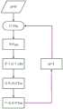
参照图1,图1是本申请实施例提供的一种电子设备环境温度检测方法的简要实施步骤流图;如图1所示,所述方法包括:Referring to Fig. 1, Fig. 1 is a flow chart of the brief implementation steps of a method for detecting the ambient temperature of an electronic device provided in an embodiment of the present application; as shown in Fig. 1 , the method includes:
步骤S101,获取电子设备内部设置的热敏电阻的电阻值,根据所述热敏电阻的电阻值,计算得到电子设备的表面温度。Step S101, acquiring the resistance value of the thermistor installed inside the electronic device, and calculating the surface temperature of the electronic device according to the resistance value of the thermistor.
本申请实施例提供的一种电子设备的环境温度检测方法,首先通过现有元器件及相关方法获取设备的表面温度,亦即设备表面的壳体温度;通过获取设置在电子设备内部的热敏电阻的阻值变化,利用线性拟合的方法,测量获得热敏电阻周围的温度变化。The embodiment of the present application provides a method for detecting the ambient temperature of an electronic device. First, the surface temperature of the device, that is, the temperature of the shell on the surface of the device is obtained through the existing components and related methods; The resistance value change of the resistor is measured by the linear fitting method to obtain the temperature change around the thermistor.
具体地,在本申请的一种可选实施例中所采用的热敏电阻为负温度系数电阻(NTC,Negative Temperature Coefficient),是一种具有随温度上升电阻呈指数关系减小特性的热敏材料;在电子设备的结构内部,内置有多颗NTC分散在电子设备内部各处以获取多组不同的电阻值数据,使得测量结果更加精准;NTC一般设置在电子设备的主板与小冷板区域,在元器件布局上靠近设备的振动马达。Specifically, the thermistor used in an optional embodiment of the present application is a negative temperature coefficient resistor (NTC, Negative Temperature Coefficient), which is a thermosensitive resistor with a characteristic that the resistance decreases exponentially as the temperature rises. Materials; inside the structure of electronic equipment, there are many built-in NTCs scattered throughout the interior of the electronic equipment to obtain multiple sets of different resistance value data, making the measurement results more accurate; NTCs are generally set on the main board and small cold plate area of electronic equipment. The vibration motor is close to the equipment in the component layout.
值得说明的是,在此过程中对于单颗NTC需要连续记录多组电阻值的历史变化情况,以搭配线性拟合法的计算公式获得电子设备的表面温度。It is worth noting that in this process, for a single NTC, it is necessary to continuously record the historical changes of multiple sets of resistance values, so as to obtain the surface temperature of the electronic device with the calculation formula of the linear fitting method.
通过采集多颗布局的热敏电阻的阻值变化,以线性拟合方式计算获得电子设备的表面温度;分散设置的NTC能够更加均匀的监测电子设备完整表面的壳体温度变化,同时在计算过程中不断更新已监测到的历史电阻值作为计算输入,能够很好的确保计算结果温度变化的连续性,使得计算获得的温度结果更加准确。The surface temperature of the electronic device can be obtained through linear fitting calculation by collecting the resistance value changes of the thermistors in multiple layouts; the dispersedly set NTC can monitor the temperature change of the complete surface of the electronic device more uniformly, and at the same time during the calculation process Continuously updating the monitored historical resistance value as the calculation input can well ensure the continuity of the temperature change of the calculation result and make the temperature result obtained by the calculation more accurate.
步骤S102,获取电子设备的电气参数,根据所述电气参数,计算得到电子设备的设备热耗值;所述设备热耗值用于表征电子设备在使用过程中,由元器件的电流热效应所产生的热量值。Step S102, obtain the electrical parameters of the electronic equipment, and calculate the equipment heat consumption value of the electronic equipment according to the electrical parameters; the equipment heat consumption value is used to represent the current thermal effect of the electronic equipment during use. caloric value.
如步骤S101所述方法,通过测量热敏电阻的阻值变化计算设备表面温度,整个检测及计算过程均由电子设备本体完成,在此过程中同样需要电子设备的其他元器件共同参与完成;如,数据的处理与计算依赖于电子设备的核心处理单元——系统级芯片(SOC,System on Chip);事实上,在实际应用中电子设备除检测温度变化之外可能处于各种不同的使用负载场景,其中必定伴随着其他元器件因为通电使用导致的发热现象;在本申请实施例中将电子设备在使用过程中因元器件的电流热效应等原因所产生的热量值归类为设备热耗,属于环境温度检测的干扰因素。As in the method described in step S101, the surface temperature of the device is calculated by measuring the resistance value change of the thermistor. The entire detection and calculation process is completed by the electronic device body, and other components of the electronic device are also required to participate in the process; , the processing and calculation of data depends on the core processing unit of the electronic equipment - system-on-chip (SOC, System on Chip); in fact, in practical applications, electronic equipment may be under various loads other than detecting temperature changes Scenarios, which must be accompanied by the heating phenomenon caused by other components due to power-on use; in the embodiment of this application, the heat value generated by the current heating effect of components during the use of electronic equipment is classified as equipment heat consumption, It belongs to the interference factor of ambient temperature detection.
在本申请实施例中,对于电子设备自身工作产生设备热耗的场景大致归类为两部分:设备充电模式及设备放电模式;参照图2,图2是本申请实施例提供的一种电子设备的元器件布局连接关系图;如图2所示,在常规充电状态下,通过通用串行总线(USB,UniversalSerial Bus)接口接入充电电源,Ibus表示充电电流,Vbus表示充电电压;随后充电电流流向充电芯片进行电力参数装,最终接入设备电池进行电力存储;而在放电状态下,电能由充点芯片释放至电芯,以供给设备电芯及系统能够正常工作,Ibat为电芯电流,Vbat为电芯电压。In the embodiment of the present application, the scene of the heat consumption of the electronic device itself is roughly classified into two parts: the device charging mode and the device discharging mode; refer to Fig. 2, which is an electronic device provided by the embodiment of the present application Layout connection diagram of the components and parts; as shown in Figure 2, in the normal charging state, the charging power supply is connected through the Universal Serial Bus (USB, UniversalSerial Bus) interface, Ibus represents the charging current, and Vbus represents the charging voltage; then The charging current flows to the charging chip for power parameter installation, and finally connects to the battery of the device for power storage; while in the discharging state, the electric energy is released from the charging point chip to the battery core to supply the equipment battery core and systemto work normally. Core current, Vbat is the battery voltage.
由于原器件内部线路存在材料电阻,当电流通过时必定会引发电流的热效应从而产生热量,正确评估电子设备运行过程中产生的设备热耗,是消除设备热耗对壳体表面温度的影响的重要步骤。Due to the material resistance of the internal circuit of the original device, when the current passes through, it will inevitably cause the thermal effect of the current to generate heat. Correctly evaluating the heat consumption of the equipment generated during the operation of the electronic equipment is an important factor to eliminate the influence of the heat consumption of the equipment on the surface temperature of the shell. step.
步骤S103,根据所述设备热耗值,计算得到电子设备的表面温升值;所述表面温升值为所述设备热耗值对所述电子设备造成的温度升高量。Step S103 , calculating a surface temperature rise value of the electronic device according to the heat consumption value of the device; the surface temperature rise value is a temperature rise amount of the electronic device caused by the heat consumption value of the device.
承接步骤S102,在确定由电子设备工作状态下各元器件导致的设备热耗后,需要将产生的热量具体量化为温度数值上的变化,即电子设备的表面温升;在本申请实施例中,采用递归计算的方式,由前一时刻的设备表面温升值与当前时刻新增的设备热耗共同获得下一时刻的设备表面温升。Following step S102, after determining the heat consumption of the equipment caused by each component in the working state of the electronic equipment, it is necessary to quantify the heat generated as a change in the temperature value, that is, the surface temperature rise of the electronic equipment; in the embodiment of this application , using a recursive calculation method, the equipment surface temperature rise at the next moment is jointly obtained from the equipment surface temperature rise at the previous moment and the newly added equipment heat consumption at the current moment.
具体地,参照图3,图3是本申请实施例提供的一种设备表面温升值的时间-温度变化统计图;如图3所示,横坐标表示具体地时间变化,纵坐标表示具体温度值,Δt为时间间隔,ΔTn表示n*Δt时刻的具体温升,Pn表示时刻n下电子设备产生的设备热耗值;在图3中,按照坐标轴箭头所指示的方向,随着单位时间间隔Δt的时间变化各时刻的设备热耗值及其对应的表面温升值;值得说明的是,在此过程中,初始时刻温升可以直接通过测试数据获得。Specifically, referring to Fig. 3, Fig. 3 is a time-temperature change statistical diagram of the surface temperature rise value of a device provided by the embodiment of the present application; as shown in Fig. 3, the abscissa represents the specific time change, and the ordinate represents the specific temperature value , Δt is the time interval, ΔTn represents the specific temperature rise at time n*Δt, Pn represents the heat consumption value of the equipment generated by the electronic equipment at time n; in Figure 3, according to the direction indicated by the arrow of the coordinate axis, with the unit The time interval Δt changes the heat consumption value of the equipment at each moment and the corresponding surface temperature rise value; it is worth noting that in this process, the temperature rise at the initial moment can be directly obtained from the test data.
热耗与温度的变化关系为前后连续的,且在时间尺度上由前一时刻的表面温升值与当前时刻的设备热耗值相叠加共同组成当前时刻的表面温升值;同时,温度的自然熵变遵循时间衰减变化原则,在表面温升的数值计算中引入时间衰减函数e(-β*Δt)以表达历史热耗温度随时间的变化关系,能够更加准确的获得电子设备表面温度的变化关系。The change relationship between heat consumption and temperature is continuous, and on the time scale, the surface temperature rise value at the previous moment and the equipment heat consumption value at the current moment are superimposed to form the surface temperature rise value at the current moment; at the same time, the natural entropy of temperature Following the principle of time decay change, the time decay function e(-β*Δt) is introduced in the numerical calculation of surface temperature rise to express the change relationship of historical heat consumption temperature with time, which can more accurately obtain the change relationship of surface temperature of electronic equipment .
步骤S104,根据所述表面温度和所述表面温升值,计算得到所述电子设备周围的环境温度。Step S104, according to the surface temperature and the surface temperature rise value, calculate the ambient temperature around the electronic device.
在获得电子设备的表面温度和表面温升值后,即可计算获得电子设备周围的环境温度;在本申请实施例中,所采取的处理思想为在测量获得的电子设备表面温度基础上,消除电子设备热耗与表面温升值对表面温度造成的影响,从而正确的测量出电子设备所处的环境温度。After obtaining the surface temperature and surface temperature rise of the electronic device, the ambient temperature around the electronic device can be calculated; in the embodiment of this application, the processing idea adopted is to eliminate the electronic The influence of equipment heat consumption and surface temperature rise on surface temperature, so as to correctly measure the ambient temperature of electronic equipment.
参照图4,图4是本申请实施例提供的一种电子设备环境温度检测的逻辑框图;从首次逻辑循环n=0开始,依次计算设备热耗值Pn,由设备热耗值获得累计温升值ΔTn,累计温升值ΔTn将同步影响检测得到的电子设备的表面温度;最后从壳体温度Tsn中消除累计温升值ΔTn带来的误差影响,即可获得准确的环境温度Tan;上述逻辑步骤依次对应本申请实施例提供的一种电子设备环境温度检测方法中,步骤S101-步骤S104中的所述内容;获得当前时刻的环境温度后,再重新进入下一个检测循环,执行如步骤S101至步骤S104中的相关方法,就能持续计算电子设备周围环境温度。Referring to Fig. 4, Fig. 4 is a logic block diagram of an electronic device ambient temperature detection provided by the embodiment of the present application; starting from the first logic cycle n=0, the heat consumption value Pn of the equipment is calculated in sequence, and the cumulative temperature rise value is obtained from the heat consumption value of the equipment ΔTn , the cumulative temperature rise value ΔTn will synchronously affect the detected surface temperature of the electronic device; finally, the accurate ambient temperature Tan can be obtained by eliminating the error effect caused by the cumulative temperature rise value ΔT n from the shell temperature Tsn; The above logical steps correspond in turn to the content in step S101-step S104 in a method for detecting the ambient temperature of an electronic device provided in the embodiment of the present application; after obtaining the ambient temperature at the current moment, re-enter the next detection cycle and execute as follows The related methods in step S101 to step S104 can continuously calculate the ambient temperature of the electronic device.
综上所述,本申请实施例提供的一种电子设备环境温度检测方法,首先通过读取设置在电子设备内部的热敏电阻的电阻值,通过计算得到电子设备的表面温度;进而通过电子设备的电气参数得到电子设备的设备热耗值;设备热耗值即为电子设备在使用过程中,由元器件所产生的热量值;由设备热耗值,计算得到电子设备的表面温升值;表面温升值为设备热耗值对电子设备造成的温度升高量;最后根据表面温度和表面温升值,共同计算得到电子设备周围的环境温度,以此抵消电子设备的自身发热对热敏电阻的变化影响,提高了对环境温度的检测精准度。To sum up, the method for detecting the ambient temperature of an electronic device provided by the embodiment of the present application first obtains the surface temperature of the electronic device through calculation by reading the resistance value of the thermistor installed inside the electronic device; The electrical parameters of the electronic equipment can be used to obtain the equipment heat consumption value of the electronic equipment; the equipment heat consumption value is the heat value generated by the components during the use of the electronic equipment; the surface temperature rise value of the electronic equipment is calculated from the equipment heat consumption value; the surface The temperature rise value is the temperature rise caused by the heat consumption value of the equipment to the electronic equipment; finally, according to the surface temperature and the surface temperature rise value, the ambient temperature around the electronic equipment is jointly calculated to offset the self-heating of the electronic equipment to the thermistor. Influence, improve the detection accuracy of the ambient temperature.
参照图5,图5是本申请实施例提供的一种电子设备环境温度检测方法的完整实施步骤流图;如图5所示,所示方法包括:Referring to FIG. 5, FIG. 5 is a flowchart of complete implementation steps of a method for detecting the ambient temperature of an electronic device provided in the embodiment of the present application; as shown in FIG. 5, the shown method includes:
步骤S201,获取电子设备内部设置的热敏电阻的电阻值,根据所述热敏电阻的电阻值,计算得到电子设备的表面温度。Step S201, acquiring the resistance value of the thermistor installed inside the electronic device, and calculating the surface temperature of the electronic device according to the resistance value of the thermistor.
本步骤具体可参照上述步骤S101,本实施例此处不再赘述。For details of this step, reference may be made to the above step S101, which will not be repeated here in this embodiment.
在一种可选的实施例中,所述步骤S201还包括:In an optional embodiment, the step S201 also includes:
子步骤S2011,获取所述热敏电阻的电阻值;所述电阻值包括:热敏电阻的当前电阻值与历史电阻值。Sub-step S2011, acquiring the resistance value of the thermistor; the resistance value includes: the current resistance value and the historical resistance value of the thermistor.
对于设置在电子设备内部的单颗NTC,以固定时间间隔连续记录其电阻值的变化情况;在除过初始时刻外的任一时刻下,获取的单颗NTC的电阻值都包括:当前电阻值与历史电阻值。For a single NTC set inside the electronic device, the change of its resistance value is continuously recorded at fixed time intervals; at any time except the initial time, the obtained resistance value of a single NTC includes: the current resistance value with historical resistance values.
具体地,可通过NTC所在的内部集成电路参数(NTC两端的电压及流过的电流值)计算得到当前时刻的具体电阻值。Specifically, the specific resistance value at the current moment can be obtained by calculating the parameters of the internal integrated circuit where the NTC is located (the voltage at both ends of the NTC and the value of the current flowing through it).
子步骤S2012,根据所述电阻值构建电阻参数矩阵,根据第一拟合参数构建拟合参数矩阵。Sub-step S2012, constructing a resistance parameter matrix according to the resistance value, and constructing a fitting parameter matrix according to the first fitting parameter.
其中,第一拟合参数与热敏电阻的电阻值一一对应;拟合参数通常根据测试数据返乡拟合获得。Wherein, the first fitting parameter is in one-to-one correspondence with the resistance value of the thermistor; the fitting parameter is usually obtained by back-home fitting according to the test data.
在一种可选的实施例中,所述子步骤S2012还包括:In an optional embodiment, the substep S2012 also includes:
子步骤S20121,按照时间顺序对热敏电阻的所述当前电阻值与历史电阻值进行排序,获得电阻值队列。Sub-step S20121, sorting the current resistance value and the historical resistance value of the thermistor according to time sequence to obtain a resistance value queue.
按照热敏电阻的电阻值的获取顺序,依次将当前电阻值与历史电阻值进行排序,获得电阻值队列。According to the acquisition order of the resistance value of the thermistor, the current resistance value and the historical resistance value are sequentially sorted to obtain a resistance value queue.
例如,用

将单颗NTC的所有电阻值按照时间顺序依次排列,组成电阻值队列:
子步骤S20122,根据所述电阻值队列构建电阻参数矩阵,所述电阻参数矩阵为一阶行矩阵。Sub-step S20122, constructing a resistance parameter matrix according to the resistance value queue, and the resistance parameter matrix is a first-order row matrix.
获得电阻值队列后,将其构建为一阶线性矩阵,以参与后续的线性拟合计算;电阻值矩阵为:
子步骤S20123,按照所述热敏电阻的电阻值的排列顺序对第一拟合参数进行排列,获得拟合参数队列。Sub-step S20123, arranging the first fitting parameters according to the sequence of the resistance values of the thermistors to obtain a fitting parameter queue.
同理,对于任一电阻值都有其对应的第一拟合参数;第一拟合参数具体为拟合系数,按照与电阻值获得的时间顺序排列后,获得拟合参数队列:


子步骤S20124,根据所述拟合参数队列构建拟合参数矩阵,所述拟合参数矩阵为一阶列矩阵。Sub-step S20124, construct a fitting parameter matrix according to the fitting parameter sequence, and the fitting parameter matrix is a first-order column matrix.
获得拟合参数队列后,同样将其构建为一阶线性矩阵,以参与后续的线性拟合计算;拟合参数矩阵为:
子步骤S2013,根据所述电阻参数矩阵、所述拟合参数矩阵以及第二拟合参数获得电子设备的所述表面温度。Sub-step S2013, obtaining the surface temperature of the electronic device according to the resistance parameter matrix, the fitting parameter matrix and a second fitting parameter.
当获取到多颗NTC的多组历史电阻值后,通过如下公式计算获得电子设备的表面温度:After obtaining multiple sets of historical resistance values of multiple NTCs, the surface temperature of the electronic device is calculated by the following formula:

其中,Ts为计算获得的电子设备表面温度,T为NTC的电阻值,α为系数,C为常数,下角标m为NTC个数,上角标n为同一NTC历史电阻值的个数;α、C通常根据测试数据反向拟合获得。Among them, Ts is the calculated surface temperature of the electronic equipment, T is the resistance value of the NTC, α is a coefficient, C is a constant, the subscript m is the number of NTCs, and the superscript n is the number of historical resistance values of the same NTC; α and C are usually obtained by inverse fitting of test data.
在一种可选的实施例中,所述子步骤S2013还包括:In an optional embodiment, the substep S2013 also includes:
子步骤S20131,获取所述电阻参数矩阵与所述拟合参数矩阵的乘积结果。Sub-step S20131, obtaining the product result of the resistance parameter matrix and the fitting parameter matrix.
参照子步骤S2013所述内容,拟合计算公式中,


子步骤S20132,获取所述乘积结果与第二拟合参数的求和结果,将所述求和结果作为电子设备的表面温度的值。Sub-step S20132, obtaining the summation result of the product result and the second fitting parameter, and using the summation result as the value of the surface temperature of the electronic device.
将所有NTC与拟合参数矩阵的乘积结果相加后,再与第二拟合参数进行求和,并将求和结果作为电子设备的表面温度的具体值。After adding the product results of all the NTCs and the fitting parameter matrix, they are summed with the second fitting parameter, and the summing result is used as a specific value of the surface temperature of the electronic device.
步骤S202,获取电子设备的电气参数,根据所述电气参数,计算得到电子设备的设备热耗值;所述设备热耗值用于表征电子设备在使用过程中,由元器件的电流热效应所产生的热量值。Step S202, obtain the electrical parameters of the electronic equipment, and calculate the equipment heat consumption value of the electronic equipment according to the electrical parameters; the equipment heat consumption value is used to represent the current thermal effect of the components during the use of the electronic equipment caloric value.
本步骤具体可参照上述步骤S102,本实施例此处不再赘述。For details of this step, reference may be made to the above step S102, which will not be repeated here in this embodiment.
在一种可选的实施例中,所述步骤S202还包括:In an optional embodiment, the step S202 also includes:
子步骤S2021,根据所述电气参数,计算获得所述设备热耗值。电气参数包括:电子设备的充电电压值与充电电流值、电子设备的电芯电流值与电芯电压值、电子设备的充电电芯的前端阻抗值、电子设备的电芯阻抗值、以及电子设备充电芯片的输入电流值与输出电流值的比值中的一种或多种。Sub-step S2021, according to the electrical parameters, calculate and obtain the heat consumption value of the equipment. Electrical parameters include: charging voltage value and charging current value of electronic equipment, cell current value and cell voltage value of electronic equipment, front-end impedance value of charging cell of electronic equipment, cell impedance value of electronic equipment, and One or more of the ratio of the input current value to the output current value of the charging chip.
参照图2,图2所示的电子设备的元器件布局连接关系图中,由USB入口至充电电芯处的电路阻值统一表示为前端阻抗R1,电流比例A用于表示充电电流的输入电流与输出电流的比值;电芯内部的阻值表示为电芯阻抗R2。Referring to Figure 2, in the layout and connection relationship diagram of the electronic equipment shown in Figure 2, the circuit resistance from the USB inlet to the charging cell is uniformly represented as the front-end impedance R1, and the current ratio A is used to represent the input current of the charging current The ratio to the output current; the resistance inside the cell is expressed as the cell impedance R2.
按照如下公式计算得到所述电子设备的热耗值:Calculate the heat consumption value of the electronic equipment according to the following formula:

其中,P为热耗值,Ibus为充电电流,Vbus为充电电压,Ibat为电子设备的电芯电流,Vbat为电子设备的电芯电压,R1为充电电芯的前端阻抗,R2为电芯阻抗,A为充电电芯的输入电流与输出电流的比值。Among them, P is the heat consumption value, Ibus is the charging current, Vbus is the charging voltage, Ibat is the battery current of the electronic equipment, Vbat is the battery voltage of the electronic equipment, R1 is the front-end impedance of the charging battery, and R2 is the battery impedance , A is the ratio of the input current to the output current of the charging cell.
值得说明的是,在放电状态下,充电芯片的输入电流值与电压值均为0,同时默认此刻充电芯片的电流比例A也为0。此时只考虑电子设备的电芯工作的电压与电流,由于在放电模式下电芯的电流流向与充电模式相反,因此Ibat的流向相反,以参考方向表示为负电流值,计算出的设备热耗P亦为正。It is worth noting that in the discharge state, the input current value and voltage value of the charging chip are both 0, and the default current ratio A of the charging chip at this moment is also 0. At this time, only the working voltage and current of the battery cell of the electronic device are considered. Since the current flow of the battery cell in the discharge mode is opposite to that in the charge mode, the flow direction of Ibat is opposite, and the reference direction is expressed as a negative current value. The calculated heat of the device Consumption of P is also positive.
步骤S203,根据所述设备热耗值,计算得到电子设备的表面温升值;所述表面温升值为所述设备热耗值对所述电子设备造成的温度升高量。Step S203, calculating a surface temperature rise value of the electronic device according to the heat consumption value of the device; the surface temperature rise value is a temperature rise amount of the electronic device caused by the heat consumption value of the device.
本步骤具体可参照上述步骤S103,本实施例此处不再赘述。For details of this step, reference may be made to the above step S103, which will not be repeated here in this embodiment.
在一种可选的实施例中,所述步骤S203还包括:In an optional embodiment, the step S203 also includes:
子步骤S2031,获取电子设备的历史表面温升值。Sub-step S2031, acquiring the historical surface temperature rise of the electronic equipment.
其中,历史表面温升值为前一时刻的电子设备的表面温升值与时间衰减函数的乘积结果;时间衰减函数为以自然对数为底数的指数函数,自然对数的指数为衰减系数与单位时间间隔的乘积结果。Among them, the historical surface temperature rise value is the product result of the surface temperature rise value of the electronic equipment at the previous moment and the time decay function; the time decay function is an exponential function with the natural logarithm as the base, and the natural logarithm exponent is the decay coefficient and unit time The product result of the intervals.
通过如下公式计算获得电子设备的表面温升值:Calculate the surface temperature rise value of the electronic device by the following formula:

其中,其中,ΔTn+1为(n+1)*Δt时刻温升值,ΔTn为n*Δt时刻温升值,β为系数,Δt为时间间隔,A用于表示设备自身的散热能力,P为设备热耗。Among them, ΔTn+1 is the temperature rise value at (n+1)*Δt time, ΔTn is the temperature rise value at n*Δt time, β is the coefficient, Δt is the time interval, A is used to represent the heat dissipation capacity of the device itself, P is the heat consumption of the device.
子步骤S2032,根据所述设备热耗值计算得到电子设备的当前热耗温升值。Sub-step S2032, calculating the current heat consumption temperature rise value of the electronic equipment according to the equipment heat consumption value.
参照子步骤S2031中所述的计算公式,根据设备热耗值计算得到电子设备的当前热耗温升值。Referring to the calculation formula described in sub-step S2031, the current heat consumption temperature rise value of the electronic equipment is calculated according to the heat consumption value of the equipment.
在一种可选的实施例中,所述子步骤S2032还包括:In an optional embodiment, the substep S2032 also includes:
子步骤S20321,获取所述设备热耗值与电子设备的散热能力系数值的比值,和1与时间衰减函数的差值的相乘结果,得到所述电子设备的当前热耗温升值;其中,所述时间衰减函数为以自然对数为底数的指数函数,自然对数的指数为衰减系数与单位时间间隔的乘积结果。Sub-step S20321, obtain the ratio of the heat consumption value of the device to the heat dissipation capacity coefficient value of the electronic device, and the multiplication result of the difference between 1 and the time decay function to obtain the current heat consumption temperature rise of the electronic device; wherein, The time attenuation function is an exponential function with natural logarithm as the base, and the exponent of natural logarithm is the product result of the attenuation coefficient and the unit time interval.
参照子步骤S2031中所述计算公式,可将当前热耗温升值大致分为两部分;其中
子步骤S2033,获取所述当前热耗温升值与历史表面温升值的求和结果,得到所述电子设备的当前表面温升值。Sub-step S2033, obtaining the summation result of the current heat consumption temperature rise and the historical surface temperature rise to obtain the current surface temperature rise of the electronic device.
当前热耗温升值与历史表面温升值进行求和后,即可获得电子设备的当前表面温升值;由于热耗与温度的变化关系为前后连续的,且在时间尺度上由前一时刻的表面温升值与当前时刻的设备热耗值相叠加共同组成当前时刻的表面温升值。After summing the current heat consumption temperature rise and the historical surface temperature rise, the current surface temperature rise of the electronic equipment can be obtained; since the relationship between heat consumption and temperature changes is continuous, and on the time scale, the surface temperature rise at the previous moment The temperature rise value and the equipment heat consumption value at the current moment are superimposed to form the surface temperature rise value at the current moment.
步骤S204,根据所述表面温度和所述表面温升值,计算得到所述电子设备周围的环境温度。Step S204, calculating the ambient temperature around the electronic device according to the surface temperature and the surface temperature rise value.
本步骤具体可参照上述步骤S104,本实施例此处不再赘述。For details of this step, reference may be made to the above step S104, which will not be repeated here in this embodiment.
可选的,所述步骤S204还包括:Optionally, the step S204 also includes:
子步骤S2041,获取电子设备的所述表面温度与所述表面温升值的差值,得到所述电子设备周围的环境温度。Sub-step S2041, obtaining the difference between the surface temperature of the electronic device and the surface temperature rise value to obtain the ambient temperature around the electronic device.
根据步骤S201获得的电子设备表面温度值与步骤S203获得的电子设备表面温升,即可获得电子设备周围的环境温度。According to the surface temperature value of the electronic device obtained in step S201 and the temperature rise of the surface of the electronic device obtained in step S203, the ambient temperature around the electronic device can be obtained.
将上述两项结果数值作差:Take the difference between the above two results:
Ta=Ts-ΔTTa =Ts -ΔT
其中,Ta为电子设备周围环境温度,Ts为电子设备表面温度,ΔT为电子设备表面温升;最终结果Ta即为电子设备周围的环境温度。Among them, Ta is the ambient temperature around the electronic equipment, Ts is the surface temperature of the electronic equipment, ΔT is the surface temperature rise of the electronic equipment; the final result Ta is the ambient temperature around the electronic equipment.
步骤S205,根据电子设备的所述表面温升值与电子设备周围的环境温度的变化结果,确定所述电子设备的表面温度升高的原因。Step S205, according to the change result of the surface temperature rise value of the electronic device and the ambient temperature around the electronic device, determine the cause of the rise in the surface temperature of the electronic device.
根据电子设备的表面温升值与电子设备周围的环境温度的变化结果,能够明确电子设备的表面温度升高的具体原因,以便后续通过针对性操作改善电子设备的温度过高问题。According to the change results of the surface temperature rise of the electronic equipment and the ambient temperature around the electronic equipment, the specific reasons for the increase of the surface temperature of the electronic equipment can be clarified, so that the problem of excessive temperature of the electronic equipment can be improved through targeted operations in the future.
步骤S206,若电子设备的所述表面温升值大于或等于第一设备温度阈值,且电子设备周围的环境温度小于第一环境温度阈值,则确定电子设备的表面温度升高由所述电子设备的设备热耗造成的。Step S206, if the surface temperature rise value of the electronic device is greater than or equal to the first device temperature threshold, and the ambient temperature around the electronic device is lower than the first ambient temperature threshold, then determine that the electronic device's surface temperature rise is caused by the electronic device's temperature threshold. caused by equipment heat loss.
参照图6,图6是本申请实施例提供的一种电子设备发热原因诊断流程示意图;在电子设备的表面温度(壳体温度)以超过门限值的情况下,确定电子设备当前存在发热问题。Referring to FIG. 6, FIG. 6 is a schematic diagram of a diagnosis process for the cause of heating of an electronic device provided by an embodiment of the present application; when the surface temperature (housing temperature) of the electronic device exceeds a threshold value, it is determined that the electronic device currently has a heating problem .
如图6内容所示,在一种实施例中,电子设备所处的环境温度为25摄氏度;从前台应用开始依次判断各温度状态与门限阈值的关系,对于电子设备的表面壳体温度:本申请实施例中认为壳体温度在轻载放电状态下高于37℃、轻载充电状态下高于39℃;或重载放电状态下高于40℃、重载充电状态下高于42℃,则认为壳体温度以超过门限阈值;反之则认为电子设备并未出现过热问题As shown in Figure 6, in one embodiment, the ambient temperature of the electronic device is 25 degrees Celsius; starting from the foreground application, the relationship between each temperature state and the threshold value is sequentially judged. For the surface shell temperature of the electronic device: In the application examples, it is considered that the temperature of the housing is higher than 37°C in the light-load discharge state, and higher than 39°C in the light-load charge state; or higher than 40°C in the heavy-load discharge state, and higher than 42°C in the heavy-load charge state, If the case temperature is considered to exceed the threshold; otherwise, it is considered that the electronic device does not have an overheating problem
在壳温超过门限阈值后,在现实判断过程中,首先判断电子设备的温度变化是否为环境引起,在本申请实施例中,认为常规状态下平均室温维持在25℃,若环境温度超过此温度值,则确定电子设备的表面温度升高是环境致热;相对则认为电子设备的表面温度升高是由设备热耗本身所导致的。After the case temperature exceeds the threshold value, in the actual judgment process, it is first judged whether the temperature change of the electronic device is caused by the environment. In the embodiment of this application, it is considered that the average value, it is determined that the increase in the surface temperature of the electronic device is caused by the environment; in contrast, it is considered that the increase in the surface temperature of the electronic device is caused by the heat loss of the device itself.
进一步地,若充电热耗大于门限值,则表明设备热耗的温度来源是充电引起的,在本申请实施例中,当灭屏状态下充电功耗高于3W、亮屏充电下功率高于500mW,则认为充电热耗大于门限阈值,将发热原因归咎于充电制热,可通过简单断开充电来限制充电发热。Furthermore, if the charging heat consumption is greater than the threshold value, it indicates that the temperature source of the heat consumption of the device is caused by charging. In the embodiment of this application, when the charging power consumption is higher than 3W when the screen is off, and the power consumption is high when the screen is on, If the charging heat consumption is greater than 500mW, it is considered that the charging heat consumption is greater than the threshold value, and the cause of the heating is attributed to the charging heating, and the charging heating can be limited by simply disconnecting the charging.
此外,若整机功耗大于门限阈值,则说明设备热耗并非由充电导致,而是设备的其他元器件工作用电引起;在本申请实施例中,认为整机功耗在轻载模式下高于720mA,或重载模式下高于900mA,则判断整机功耗已超过功耗门限阈值;具体地,在整机功耗中出现屏幕功耗大于200毫安(mA,milliampere电流计量单位)、网络功耗大于150mA、后台功耗大于50mA、亦或前台功耗在轻载模式下高于300mA,重载模式下高于500mA情况中的任意一种情况,都视为其对应工作模块功耗超过功耗阈值;特别地,当确定前台功耗超过门限阈值后,还需判断设备的前台负载是否正常;若前台负载正常,则判断致热原因为正常前台制热,相反则表明致热原因为异常前台制热。对于元件功耗的致热阈值标准,本申请实施例不做限制,开发人员可根据实际情况进行调整;值得说明的是,若电子设备的整体整机功耗大于门限阈值,则表明该电子设备自身的但热能力较差。In addition, if the power consumption of the whole machine is greater than the threshold threshold, it means that the heat consumption of the device is not caused by charging, but by the power consumption of other components of the device; If it is higher than 720mA, or higher than 900mA in heavy load mode, it is judged that the power consumption of the whole machine has exceeded the power consumption threshold; ), the network power consumption is greater than 150mA, the background power consumption is greater than 50mA, or the foreground power consumption is higher than 300mA in light load mode, and higher than 500mA in heavy load mode. The power consumption exceeds the power consumption threshold; in particular, when it is determined that the power consumption of the foreground exceeds the threshold, it is necessary to determine whether the foreground load of the device is normal; The cause of heat is abnormal front heating. The embodiment of this application does not limit the heating threshold standard of component power consumption, and developers can adjust it according to the actual situation; it is worth noting that if the overall power consumption of the electronic device is greater than the threshold threshold, it indicates that the electronic device Own but less thermally capable.
在一种可选的实施例中,所述步骤S206还包括:In an optional embodiment, the step S206 also includes:
在确定电子设备的表面温度升高由所述电子设备的设备热耗造成的情况下,所述方法还包括:Where it is determined that the increase in surface temperature of the electronic device is caused by device heat dissipation of the electronic device, the method further includes:
子步骤S2061,降低所述电子设备的电芯的工作频率,直至所述电子设备的表面温升值等于或小于上一时刻电子设备的表面温升值。Sub-step S2061, reducing the operating frequency of the battery cell of the electronic device until the surface temperature rise of the electronic device is equal to or less than the surface temperature rise of the electronic device at the previous moment.
在实际应用中,可通过下调设备电芯的工作频率减少电芯对于数据处理的运算负载,从而降低其引起的设备热耗,最终控制表面温升值的降低,防止热量持续累计造成设备壳体表面不断升高。In practical applications, it is possible to reduce the operational load of the battery cells for data processing by lowering the operating frequency of the equipment cells, thereby reducing the heat consumption of the equipment caused by it, and finally controlling the reduction of the surface temperature rise to prevent the continuous accumulation of heat from causing damage to the surface of the equipment shell. keep rising.
子步骤S2062,降低所述电子设备的电芯的工作供电功率,直至所述电子设备的表面温升值等于或小于上一时刻电子设备的表面温升值。Sub-step S2062, reducing the working power of the battery cell of the electronic device until the surface temperature rise of the electronic device is equal to or less than the surface temperature rise of the electronic device at the previous moment.
同理,还可通过限制电子设备的电芯的耗电功率,控制在工作状态下的功耗上限,降低其引起的设备热耗,最终控制表面温升值的降低,防止热量持续累计造成设备壳体表面不断升高。In the same way, by limiting the power consumption of the battery cells of electronic equipment, the upper limit of power consumption in the working state can be controlled to reduce the heat consumption of the equipment caused by it, and finally control the reduction of the surface temperature rise to prevent the continuous accumulation of heat from causing damage to the equipment shell. The body surface continues to rise.
限制设备电芯的供电功耗后,系统将随即同步对设备的其他元器件的工作功耗进行限制,全方位降低电子设备的整机功耗。After limiting the power consumption of the device's battery, the system will simultaneously limit the power consumption of other components of the device to reduce the overall power consumption of the electronic device in an all-round way.
步骤S207,若电子设备的所述表面温升值小于第一设备温度阈值,且电子设备周围的环境温度大于或等于第一环境温度阈值,则确定电子设备的表面温度升高是由所述电子设备所处的环境温度造成的。Step S207, if the surface temperature rise of the electronic device is less than the first device temperature threshold, and the ambient temperature around the electronic device is greater than or equal to the first ambient temperature threshold, then it is determined that the increase in the surface temperature of the electronic device is caused by the electronic device caused by the ambient temperature.
若在电子设备发热原因诊断流程中,环境温度已超出门限阈值,则表明当前电子设备的表面温度升高主要原因在于所处的环境;由于环境温度不属于电子设备自身的可控因素范畴,因此在该场景下通常采用澄清解释应对,提醒用户对环境控温采取相应措施。If in the process of diagnosing the cause of heating of electronic equipment, the ambient temperature has exceeded the threshold value, it indicates that the main reason for the increase in surface temperature of the current electronic equipment is the environment in which it is located; since the ambient temperature does not belong to the controllable factors of the electronic equipment itself, so In this scenario, a clarification explanation is usually used to remind the user to take corresponding measures for environmental temperature control.
综上所述,本申请实施例提供的一种电子设备环境温度检测方法,首先通过读取设置在电子设备内部的热敏电阻的电阻值,通过计算得到电子设备的表面温度;进而通过电子设备的电气参数得到电子设备的设备热耗值;设备热耗值即为电子设备在使用过程中,由元器件所产生的热量值;由设备热耗值,计算得到电子设备的表面温升值;表面温升值为设备热耗值对电子设备造成的温度升高量;最后根据表面温度和表面温升值,共同计算得到电子设备周围的环境温度,以此抵消电子设备的自身发热对热敏电阻的变化影响,提高了对环境温度的检测精准度;之后根据检测结果明晰电子设备表面温度的致热主要原因,以采取响应的解决措施对温度进行控制,保障电子设备的硬件安全与用户的人身安全。To sum up, the method for detecting the ambient temperature of an electronic device provided by the embodiment of the present application first obtains the surface temperature of the electronic device through calculation by reading the resistance value of the thermistor installed inside the electronic device; The electrical parameters of the electronic equipment can be used to obtain the equipment heat consumption value of the electronic equipment; the equipment heat consumption value is the heat value generated by the components during the use of the electronic equipment; the surface temperature rise value of the electronic equipment is calculated from the equipment heat consumption value; the surface The temperature rise value is the temperature rise caused by the heat consumption value of the equipment to the electronic equipment; finally, according to the surface temperature and the surface temperature rise value, the ambient temperature around the electronic equipment is jointly calculated to offset the self-heating of the electronic equipment to the thermistor. After that, according to the detection results, the main reason for the heating of the surface temperature of electronic equipment is clarified, and corresponding solutions are taken to control the temperature to ensure the hardware safety of electronic equipment and the personal safety of users.
参照图7,图7是本申请实施例提供的一种电子设备环境温度检测装置的功能模块装置组成示意图;如图7所示,所述装置包括:Referring to FIG. 7, FIG. 7 is a schematic diagram of the functional module device composition of an electronic equipment ambient temperature detection device provided by the embodiment of the present application; as shown in FIG. 7, the device includes:
表面温度确定模块S301,用于获取电子设备内部设置的热敏电阻的电阻值,根据所述热敏电阻的电阻值,计算得到电子设备的表面温度;The surface temperature determination module S301 is used to obtain the resistance value of the thermistor installed inside the electronic device, and calculate the surface temperature of the electronic device according to the resistance value of the thermistor;
可选的,所述表面温度确定模块S301还包括:Optionally, the surface temperature determination module S301 also includes:
电阻值获取子模块,用于获取所述热敏电阻的电阻值;所述电阻值包括:热敏电阻的当前电阻值与历史电阻值。The resistance value obtaining sub-module is used to obtain the resistance value of the thermistor; the resistance value includes: the current resistance value and the historical resistance value of the thermistor.
计算矩阵构建子模块,用于根据所述电阻值构建电阻参数矩阵,根据第一拟合参数构建拟合参数矩阵。The calculation matrix construction sub-module is configured to construct a resistance parameter matrix according to the resistance value, and construct a fitting parameter matrix according to the first fitting parameter.
可选的,所述计算矩阵构建子模块还包括:Optionally, the calculation matrix construction submodule also includes:
电阻值队列构建单元,用于按照时间顺序对热敏电阻的所述当前电阻值与历史电阻值进行排序,获得电阻值队列。The resistance value queue construction unit is configured to sort the current resistance value and the historical resistance value of the thermistor in time order to obtain a resistance value queue.
电阻参数矩阵构建单元,用于根据所述电阻值队列构建电阻参数矩阵,所述电阻参数矩阵为一阶行矩阵。The resistance parameter matrix construction unit is configured to construct a resistance parameter matrix according to the resistance value sequence, and the resistance parameter matrix is a first-order row matrix.
拟合参数队列构建单元,按照所述热敏电阻的电阻值的排列顺序对第一拟合参数进行排列,获得拟合参数队列。The fitting parameter queue construction unit arranges the first fitting parameters according to the sequence of the resistance values of the thermistors to obtain a fitting parameter queue.
拟合参数矩阵构建单元,用于根据所述拟合参数队列构建拟合参数矩阵,所述拟合参数矩阵为一阶列矩阵。A fitting parameter matrix construction unit is configured to construct a fitting parameter matrix according to the fitting parameter queue, and the fitting parameter matrix is a first-order column matrix.
表面温度计算子模块,用于根据所述电阻参数矩阵、所述拟合参数矩阵以及第二拟合参数获得电子设备的所述表面温度。The surface temperature calculation sub-module is used to obtain the surface temperature of the electronic device according to the resistance parameter matrix, the fitting parameter matrix and the second fitting parameter.
可选的,所述表面温度计算子模块还包括:Optionally, the surface temperature calculation submodule also includes:
矩阵乘积运算单元,用于获取所述电阻参数矩阵与所述拟合参数矩阵的乘积结果。A matrix product operation unit, configured to obtain a product result of the resistance parameter matrix and the fitting parameter matrix.
表面温度计算单元,用于获取所述乘积结果与第二拟合参数的求和结果,将所述求和结果作为电子设备的表面温度的值。The surface temperature calculation unit is configured to obtain a summation result of the product result and the second fitting parameter, and use the summation result as a value of the surface temperature of the electronic device.
设备热耗值确定模块S320,用于获取电子设备的电气参数,根据所述电气参数,计算得到电子设备的设备热耗值;所述设备热耗值用于表征电子设备在使用过程中,由元器件的电流热效应所产生的热量值;The equipment heat consumption value determination module S320 is used to obtain the electrical parameters of the electronic equipment, and calculate the equipment heat consumption value of the electronic equipment according to the electrical parameters; the equipment heat consumption value is used to represent the electronic equipment during use. The calorific value generated by the current heating effect of components;
设备热耗值计算子模块,用于根据所述电气参数,计算获得所述设备热耗值。The equipment heat consumption value calculation sub-module is used to calculate and obtain the equipment heat consumption value according to the electrical parameters.
表面温升值确定模块S303,用于根据所述设备热耗值,计算得到电子设备的表面温升值;所述表面温升值为所述设备热耗值对所述电子设备造成的温度升高量;The surface temperature rise value determination module S303 is used to calculate the surface temperature rise value of the electronic device according to the heat consumption value of the device; the surface temperature rise value is the temperature rise caused by the heat consumption value of the device to the electronic device;
历史表面温升值获取子模块,用于获取电子设备的历史表面温升值。The historical surface temperature rise value acquisition sub-module is used to obtain the historical surface temperature rise value of electronic equipment.
当前热耗值计算子模块,用于根据所述设备热耗值计算得到电子设备的当前热耗温升值。The current heat consumption value calculation sub-module is used to calculate the current heat consumption temperature rise value of the electronic equipment according to the equipment heat consumption value.
可选的,所述当前热耗值计算子模块还包括:Optionally, the current heat consumption calculation submodule also includes:
当前热耗温升值计算单元,用于获取所述设备热耗值与电子设备的散热能力系数值的比值,和1与时间衰减函数的差值的相乘结果,得到所述电子设备的当前热耗温升值。The current heat consumption temperature rise calculation unit is used to obtain the ratio of the heat consumption value of the device to the heat dissipation capacity coefficient value of the electronic device, and the multiplication result of the difference between 1 and the time decay function to obtain the current heat dissipation of the electronic device Temperature rise.
当前表面温升值计算子模块,用于获取所述当前热耗温升值与历史表面温升值的求和结果,得到所述电子设备的当前表面温升值。The current surface temperature rise calculation sub-module is used to obtain the summation result of the current heat consumption temperature rise and the historical surface temperature rise to obtain the current surface temperature rise of the electronic device.
环境温度确定模块S304,用于根据所述表面温度和所述表面温升值,计算得到所述电子设备周围的环境温度。The ambient temperature determination module S304 is configured to calculate the ambient temperature around the electronic device according to the surface temperature and the surface temperature rise value.
可选的,所述环境温度确定模块S304还包括:Optionally, the ambient temperature determination module S304 also includes:
环境温度确定子模块,用于获取电子设备的所述表面温度与所述表面温升值的差值,得到所述电子设备周围的环境温度。The ambient temperature determining submodule is configured to obtain a difference between the surface temperature of the electronic device and the surface temperature rise value to obtain the ambient temperature around the electronic device.
可选的,所述装置还包括:Optionally, the device also includes:
表面温升确定模块,用于根据电子设备的所述表面温升值与电子设备周围的环境温度的变化结果,确定所述电子设备的表面温度升高的原因。The surface temperature rise determination module is configured to determine the cause of the rise in the surface temperature of the electronic device according to the change result of the surface temperature rise value of the electronic device and the ambient temperature around the electronic device.
设备状态调整模块,用于在确定电子设备的表面温度升高由所述电子设备的设备热耗造成的之后,调节电子设备的工作状态。The device state adjustment module is configured to adjust the working state of the electronic device after it is determined that the increase in the surface temperature of the electronic device is caused by the heat consumption of the electronic device.
可选的,所述设备状态调整模块还包括:Optionally, the device status adjustment module further includes:
频率调整子模块,用于降低所述电子设备的电芯的工作频率,直至所述电子设备的表面温升值等于或小于上一时刻电子设备的表面温升值。The frequency adjustment sub-module is used to reduce the operating frequency of the battery cell of the electronic device until the surface temperature rise of the electronic device is equal to or less than the surface temperature rise of the electronic device at the previous moment.
功耗调整子模块,用于降低所述电子设备的电芯的工作供电功率,直至所述电子设备的表面温升值等于或小于上一时刻电子设备的表面温升值。The power consumption adjustment sub-module is used to reduce the working power supply of the electric core of the electronic device until the surface temperature rise of the electronic device is equal to or less than the surface temperature rise of the electronic device at the previous moment.
综上所述,本申请实施例提供的一种电子设备环境温度检测装置,首先通过读取设置在电子设备内部的热敏电阻的电阻值,通过计算得到电子设备的表面温度;进而通过电子设备的电气参数得到电子设备的设备热耗值;设备热耗值即为电子设备在使用过程中,由元器件所产生的热量值;由设备热耗值,计算得到电子设备的表面温升值;表面温升值为设备热耗值对电子设备造成的温度升高量;最后根据表面温度和表面温升值,共同计算得到电子设备周围的环境温度,以此抵消电子设备的自身发热对热敏电阻的变化影响,提高了对环境温度的检测精准度;之后根据检测结果明晰电子设备表面温度的致热主要原因,采取响应的解决措施,通过设备状态调整对温度进行控制,保障电子设备的硬件安全与用户的人身安全。To sum up, the device for detecting the ambient temperature of an electronic device provided by the embodiment of the present application first obtains the surface temperature of the electronic device by reading the resistance value of the thermistor installed inside the electronic device; The electrical parameters of the electronic equipment can be used to obtain the equipment heat consumption value of the electronic equipment; the equipment heat consumption value is the heat value generated by the components during the use of the electronic equipment; the surface temperature rise value of the electronic equipment is calculated from the equipment heat consumption value; the surface The temperature rise value is the temperature rise caused by the heat consumption value of the equipment to the electronic equipment; finally, according to the surface temperature and the surface temperature rise value, the ambient temperature around the electronic equipment is jointly calculated to offset the self-heating of the electronic equipment to the thermistor. After that, according to the detection results, the main reason for the heating of the surface temperature of electronic equipment is clarified, and corresponding solutions are taken to control the temperature through equipment status adjustment, so as to ensure the hardware safety of electronic equipment and users. personal safety.
本申请实施例中的一种电子设备环境温度检测装置可以是电子设备,也可以是电子设备中的部件,例如集成电路或芯片。该电子设备可以是终端,也可以为除终端之外的其他设备。示例性的,电子设备可以为手机、平板电脑、笔记本电脑、掌上电脑、车载电子设备、移动上网装置(Mobile Internet Device,MID)、增强现实(augmented reality,AR)/虚拟现实(virtual reality,VR)设备、机器人、可穿戴设备、超级移动个人计算机(ultra-mobile personal computer,UMPC)、上网本或者个人数字助理(personal digitalassistant,PDA)等,还可以为服务器、网络附属存储器(Network Attached Storage,NAS)、个人计算机(personal computer,PC)、电视机(television,TV)、柜员机或者自助机等,本申请实施例不作具体限定。The device for detecting the ambient temperature of an electronic device in the embodiment of the present application may be an electronic device, or may be a component in the electronic device, such as an integrated circuit or a chip. The electronic device may be a terminal, or other devices other than the terminal. Exemplarily, the electronic device may be a mobile phone, a tablet computer, a notebook computer, a handheld computer, a vehicle electronic device, a mobile Internet device (Mobile Internet Device, MID), an augmented reality (augmented reality, AR)/virtual reality (virtual reality, VR ) equipment, robots, wearable devices, ultra-mobile personal computer (ultra-mobile personal computer, UMPC), netbook or personal digital assistant (personal digital assistant, PDA), etc., can also serve as server, network attached storage (Network Attached Storage, NAS ), a personal computer (personal computer, PC), a television (television, TV), a teller machine or a self-service machine, etc., which are not specifically limited in this embodiment of the present application.
本申请实施例中的一种电子设备环境温度检测装置可以为具有操作系统的装置。该操作系统可以为安卓(Android)操作系统,可以为IOS操作系统,还可以为其他可能的操作系统,本申请实施例不作具体限定。The device for detecting the ambient temperature of an electronic device in the embodiment of the present application may be a device with an operating system. The operating system may be an Android operating system, an IOS operating system, or other possible operating systems, which are not specifically limited in this embodiment of the present application.
本申请实施例提供的一种电子设备环境温度检测装置能够实现1至图6的方法实施例实现的各个过程,为避免重复,这里不再赘述。The device for detecting the ambient temperature of an electronic device provided in the embodiment of the present application can realize various processes realized in the method embodiments in 1 to FIG. 6 , and details are not repeated here to avoid repetition.
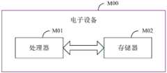
可选地,如图8所示,本申请实施例还提供一种电子设备M00,包括处理器M01和存储器M02,存储器M02上存储有可在所述处理器M01上运行的程序或指令,该程序或指令被处理器M01执行时实现上述电子设备环境温度检测方法实施例的各个步骤,且能达到相同的技术效果,为避免重复,这里不再赘述。Optionally, as shown in FIG. 8 , the embodiment of the present application also provides an electronic device M00, including a processor M01 and a memory M02, and the memory M02 stores programs or instructions that can run on the processor M01. When the program or instruction is executed by the processor M01, the steps of the above-mentioned embodiment of the method for detecting the ambient temperature of the electronic device can be realized, and the same technical effect can be achieved. To avoid repetition, details are not repeated here.
需要说明的是,本申请实施例中的电子设备包括上述所述的移动电子设备和非移动电子设备。It should be noted that the electronic devices in the embodiments of the present application include the above-mentioned mobile electronic devices and non-mobile electronic devices.
图9为实现本申请实施例的一种电子设备的硬件结构示意图。FIG. 9 is a schematic diagram of a hardware structure of an electronic device implementing an embodiment of the present application.
该电子设备1000包括但不限于:射频单元1001、网络模块1002、音频输出单元1003、输入单元1004、传感器1005、显示单元1006、用户输入单元1007、接口单元1008、存储器1009、以及处理器1010等部件。The
本领域技术人员可以理解,电子设备1000还可以包括给各个部件供电的电源(比如电池),电源可以通过电源管理系统与处理器1010逻辑相连,从而通过电源管理系统实现管理充电、放电、以及功耗管理等功能。图9中示出的电子设备结构并不构成对电子设备的限定,电子设备可以包括比图示更多或更少的部件,或者组合某些部件,或者不同的部件布置,在此不再赘述。Those skilled in the art can understand that the
其中,处理器101用于:获取电子设备内部设置的热敏电阻的电阻值,根据所述热敏电阻的电阻值,计算得到电子设备的表面温度;Wherein, the processor 101 is configured to: obtain the resistance value of the thermistor installed inside the electronic device, and calculate the surface temperature of the electronic device according to the resistance value of the thermistor;
获取电子设备的电气参数,根据所述电气参数,计算得到电子设备的设备热耗值;所述设备热耗值用于表征电子设备在使用过程中,由元器件的电流热效应所产生的热量值;Obtain the electrical parameters of the electronic equipment, and calculate the equipment heat consumption value of the electronic equipment according to the electrical parameters; the equipment heat consumption value is used to represent the heat value generated by the current thermal effect of the components during the use of the electronic equipment ;
根据所述设备热耗值,计算得到电子设备的表面温升值;所述表面温升值为所述设备热耗值对所述电子设备造成的温度升高量;According to the heat consumption value of the equipment, the surface temperature rise value of the electronic equipment is calculated; the surface temperature rise value is the temperature rise caused by the heat consumption value of the equipment to the electronic equipment;
根据所述表面温度和所述表面温升值,计算得到所述电子设备周围的环境温度。According to the surface temperature and the surface temperature rise value, the ambient temperature around the electronic device is calculated.
本申请实施例提供的一种电子设备环境温度检测方法,首先通过读取设置在电子设备内部的热敏电阻的电阻值,通过计算得到电子设备的表面温度;进而通过电子设备的电气参数得到电子设备的设备热耗值;设备热耗值即为电子设备在使用过程中,由元器件所产生的热量值;由设备热耗值,计算得到电子设备的表面温升值;表面温升值为设备热耗值对电子设备造成的温度升高量;最后根据表面温度和表面温升值,共同计算得到电子设备周围的环境温度,以此抵消电子设备的自身发热对热敏电阻的变化影响,提高了对环境温度的检测精准度。In the method for detecting the ambient temperature of an electronic device provided in the embodiment of the present application, firstly, the surface temperature of the electronic device is obtained through calculation by reading the resistance value of the thermistor installed inside the electronic device; The equipment heat consumption value of the equipment; the equipment heat consumption value is the heat value generated by the components during the use of the electronic equipment; the surface temperature rise value of the electronic equipment is calculated from the equipment heat consumption value; the surface temperature rise value is the heat value of the equipment The temperature increase caused by the consumption value of the electronic equipment; finally, according to the surface temperature and the surface temperature rise, the ambient temperature around the electronic equipment is jointly calculated, so as to offset the influence of the self-heating of the electronic equipment on the thermistor, and improve the thermal resistance. The detection accuracy of ambient temperature.
可选地,处理器1010还用于:按照时间顺序对热敏电阻的所述当前电阻值与历史电阻值进行排序,获得电阻值队列;Optionally, the
根据所述电阻值队列构建电阻参数矩阵,所述电阻参数矩阵为一阶行矩阵;Constructing a resistance parameter matrix according to the resistance value queue, the resistance parameter matrix is a first-order row matrix;
按照所述热敏电阻的电阻值的排列顺序对第一拟合参数进行排列,获得拟合参数队列;Arranging the first fitting parameters according to the sequence of the resistance values of the thermistors to obtain a fitting parameter queue;
根据所述拟合参数队列构建拟合参数矩阵,所述拟合参数矩阵为一阶列矩阵。A fitting parameter matrix is constructed according to the fitting parameter queue, and the fitting parameter matrix is a first-order column matrix.
可选的,处理器1010还用于:获取所述电阻参数矩阵与所述拟合参数矩阵的乘积结果;Optionally, the
获取所述乘积结果与第二拟合参数的求和结果,将所述求和结果作为电子设备的表面温度的值。A summation result of the product result and the second fitting parameter is obtained, and the summation result is used as a value of the surface temperature of the electronic device.
可选的,处理器1010还用于:按照如下公式计算得到所述电子设备的热耗值:Optionally, the

其中,P为热耗值,Ibus为充电电流,Vbus为充电电压,Ibat为电子设备的电芯电流,Vbat为电子设备的电芯电压,R1为充电电芯的前端阻抗,R2为电芯阻抗,A为充电电芯的输入电流与输出电流的比值。Among them, P is the heat consumption value, Ibus is the charging current, Vbus is the charging voltage, Ibat is the battery current of the electronic equipment, Vbat is the battery voltage of the electronic equipment, R1 is the front-end impedance of the charging battery, and R2 is the battery impedance , A is the ratio of the input current to the output current of the charging cell.
可选的,处理器1010还用于:获取电子设备的历史表面温升值;Optionally, the
根据所述设备热耗值计算得到电子设备的当前热耗温升值;Calculate and obtain the current heat consumption temperature rise of the electronic equipment according to the heat consumption value of the equipment;
获取所述当前热耗温升值与历史表面温升值的求和结果,得到所述电子设备的当前表面温升值。The summation result of the current heat consumption temperature rise and the historical surface temperature rise is obtained to obtain the current surface temperature rise of the electronic device.
可选的,处理器1010还用于:获取所述设备热耗值与电子设备的散热能力系数值的比值,和1与时间衰减函数的差值的相乘结果,得到所述电子设备的当前热耗温升值;Optionally, the
其中,所述时间衰减函数为以自然对数为底数的指数函数,自然对数的指数为衰减系数与单位时间间隔的乘积结果。Wherein, the time attenuation function is an exponential function with natural logarithm as the base, and the exponent of natural logarithm is the product result of the attenuation coefficient and the unit time interval.
可选的,处理器1010还用于:获取电子设备的所述表面温度与所述表面温升值的差值,得到所述电子设备周围的环境温度。Optionally, the
可选的,处理器1010还用于:根据电子设备的所述表面温升值与电子设备周围的环境温度的变化结果,确定所述电子设备的表面温度升高的原因;Optionally, the
若电子设备的所述表面温升值大于或等于第一设备温度阈值,且电子设备周围的环境温度小于第一环境温度阈值,则确定电子设备的表面温度升高由所述电子设备的设备热耗造成的;If the surface temperature rise value of the electronic device is greater than or equal to the first device temperature threshold, and the ambient temperature around the electronic device is lower than the first ambient temperature threshold, it is determined that the increase in the surface temperature of the electronic device is caused by the heat consumption of the electronic device. Caused;
若电子设备的所述表面温升值小于第一设备温度阈值,且电子设备周围的环境温度大于或等于第一环境温度阈值,则确定电子设备的表面温度升高是由所述电子设备所处的环境温度造成的。If the surface temperature rise of the electronic device is less than the first device temperature threshold, and the ambient temperature around the electronic device is greater than or equal to the first ambient temperature threshold, it is determined that the increase in the surface temperature of the electronic device is caused by the electronic device caused by ambient temperature.
可选的,处理器1010还用于:降低所述电子设备的电芯的工作频率,直至所述电子设备的表面温升值等于或小于上一时刻电子设备的表面温升值;Optionally, the
降低所述电子设备的电芯的工作供电功率,直至所述电子设备的表面温升值等于或小于上一时刻电子设备的表面温升值。Reduce the working power supply of the electric core of the electronic device until the surface temperature rise of the electronic device is equal to or less than the surface temperature rise of the electronic device at the previous moment.
本申请实施例提供的一种电子设备环境温度检测方法,首先通过读取设置在电子设备内部的热敏电阻的电阻值,通过计算得到电子设备的表面温度;进而通过电子设备的电气参数得到电子设备的设备热耗值;设备热耗值即为电子设备在使用过程中,由元器件所产生的热量值;由设备热耗值,计算得到电子设备的表面温升值;表面温升值为设备热耗值对电子设备造成的温度升高量;最后根据表面温度和表面温升值,共同计算得到电子设备周围的环境温度,以此抵消电子设备的自身发热对热敏电阻的变化影响,提高了对环境温度的检测精准度;之后根据检测结果明晰电子设备表面温度的致热主要原因,以采取响应的解决措施对温度进行控制,保障电子设备的硬件安全与用户的人身安全。In the method for detecting the ambient temperature of an electronic device provided in the embodiment of the present application, firstly, the surface temperature of the electronic device is obtained through calculation by reading the resistance value of the thermistor installed inside the electronic device; The equipment heat consumption value of the equipment; the equipment heat consumption value is the heat value generated by the components during the use of the electronic equipment; the surface temperature rise value of the electronic equipment is calculated from the equipment heat consumption value; the surface temperature rise value is the heat value of the equipment The temperature increase caused by the consumption value of the electronic equipment; finally, according to the surface temperature and the surface temperature rise, the ambient temperature around the electronic equipment is jointly calculated, so as to offset the influence of the self-heating of the electronic equipment on the thermistor, and improve the thermal resistance. The detection accuracy of the ambient temperature; then, according to the detection results, the main cause of the heating of the surface temperature of the electronic equipment is clarified, and corresponding solutions are taken to control the temperature to ensure the hardware safety of the electronic equipment and the personal safety of the user.
应理解的是,本申请实施例中,输入单元1004可以包括图形处理器(GraphicsProcessing Unit,GPU)10041和麦克风10042,图形处理器10041对在视频捕获模式或图像捕获模式中由图像捕获装置(如摄像头)获得的静态图片或视频的图像数据进行处理。显示单元1006可包括显示面板10061,可以采用液晶显示器、有机发光二极管等形式来配置显示面板10061。用户输入单元1007包括触控面板10071以及其他输入设备10072中的至少一种。触控面板10071,也称为触摸屏。触控面板10071可包括触摸检测装置和触摸控制器两个部分。其他输入设备10072可以包括但不限于物理键盘、功能键(比如音量控制按键、开关按键等)、轨迹球、鼠标、操作杆,在此不再赘述。It should be understood that, in this embodiment of the present application, the
存储器1009可用于存储软件程序以及各种数据。存储器1009可主要包括存储程序或指令的第一存储区和存储数据的第二存储区,其中,第一存储区可存储操作系统、至少一个功能所需的应用程序或指令(比如声音播放功能、图像播放功能等)等。此外,存储器1009可以包括易失性存储器或非易失性存储器,或者,存储器1009可以包括易失性和非易失性存储器两者。其中,非易失性存储器可以是只读存储器(Read-Only Memory,ROM)、可编程只读存储器(Programmable ROM,PROM)、可擦除可编程只读存储器(Erasable PROM,EPROM)、电可擦除可编程只读存储器(Electrically EPROM,EEPROM)或闪存。易失性存储器可以是随机存取存储器(Random Access Memory,RAM),静态随机存取存储器(Static RAM,SRAM)、动态随机存取存储器(Dynamic RAM,DRAM)、同步动态随机存取存储器(Synchronous DRAM,SDRAM)、双倍数据速率同步动态随机存取存储器(Double Data Rate SDRAM,DDRSDRAM)、增强型同步动态随机存取存储器(Enhanced SDRAM,ESDRAM)、同步连接动态随机存取存储器(Synch link DRAM,SLDRAM)和直接内存总线随机存取存储器(Direct Rambus RAM,DRRAM)。本申请实施例中的存储器1009包括但不限于这些和任意其它适合类型的存储器。The
处理器1010可包括一个或多个处理单元;可选的,处理器1010集成应用处理器和调制解调处理器,其中,应用处理器主要处理涉及操作系统、用户界面和应用程序等的操作,调制解调处理器主要处理无线通信信号,如基带处理器。可以理解的是,上述调制解调处理器也可以不集成到处理器1010中。The
本申请实施例还提供一种可读存储介质,所述可读存储介质上存储有程序或指令,该程序或指令被处理器执行时实现上述电子设备环境温度检测方法实施例的各个过程,且能达到相同的技术效果,为避免重复,这里不再赘述。The embodiment of the present application also provides a readable storage medium, where a program or instruction is stored on the readable storage medium, and when the program or instruction is executed by a processor, each process of the above-mentioned embodiment of the method for detecting the ambient temperature of an electronic device is implemented, and The same technical effect can be achieved, so in order to avoid repetition, details will not be repeated here.
其中,所述处理器为上述实施例中所述的电子设备中的处理器。所述可读存储介质,包括计算机可读存储介质,如计算机只读存储器ROM、随机存取存储器RAM、磁碟或者光盘等。Wherein, the processor is the processor in the electronic device described in the above embodiments. The readable storage medium includes a computer-readable storage medium, such as a computer read-only memory ROM, a random access memory RAM, a magnetic disk or an optical disk, and the like.
本申请实施例另提供了一种芯片,所述芯片包括处理器和通信接口,所述通信接口和所述处理器耦合,所述处理器用于运行程序或指令,实现上述电子设备环境温度检测方法实施例的各个过程,且能达到相同的技术效果,为避免重复,这里不再赘述。The embodiment of the present application further provides a chip, the chip includes a processor and a communication interface, the communication interface is coupled to the processor, and the processor is used to run programs or instructions to implement the above method for detecting the ambient temperature of electronic equipment The various processes of the embodiment can achieve the same technical effect, so in order to avoid repetition, details are not repeated here.
应理解,本申请实施例提到的芯片还可以称为系统级芯片、系统芯片、芯片系统或片上系统芯片等。It should be understood that the chips mentioned in the embodiments of the present application may also be called system-on-chip, system-on-chip, system-on-a-chip, or system-on-a-chip.
本申请实施例提供一种计算机程序产品,该程序产品被存储在存储介质中,该程序产品被至少一个处理器执行以实现如上述电子设备环境温度检测方法实施例的各个过程,且能达到相同的技术效果,为避免重复,这里不再赘述。The embodiment of the present application provides a computer program product, the program product is stored in a storage medium, and the program product is executed by at least one processor to implement the various processes in the above-mentioned embodiment of the method for detecting the ambient temperature of an electronic device, and can achieve the same To avoid repetition, the technical effects will not be repeated here.
需要说明的是,在本文中,术语“包括”、“包含”或者其任何其他变体意在涵盖非排他性的包含,从而使得包括一系列要素的过程、方法、物品或者装置不仅包括那些要素,而且还包括没有明确列出的其他要素,或者是还包括为这种过程、方法、物品或者装置所固有的要素。在没有更多限制的情况下,由语句“包括一个……”限定的要素,并不排除在包括该要素的过程、方法、物品或者装置中还存在另外的相同要素。此外,需要指出的是,本申请实施方式中的方法和装置的范围不限按示出或讨论的顺序来执行功能,还可包括根据所涉及的功能按基本同时的方式或按相反的顺序来执行功能,例如,可以按不同于所描述的次序来执行所描述的方法,并且还可以添加、省去、或组合各种步骤。另外,参照某些示例所描述的特征可在其他示例中被组合。It should be noted that, in this document, the term "comprising", "comprising" or any other variation thereof is intended to cover a non-exclusive inclusion such that a process, method, article or apparatus comprising a set of elements includes not only those elements, It also includes other elements not expressly listed, or elements inherent in the process, method, article, or device. Without further limitations, an element defined by the phrase "comprising a ..." does not preclude the presence of additional identical elements in the process, method, article, or apparatus comprising that element. In addition, it should be pointed out that the scope of the methods and devices in the embodiments of the present application is not limited to performing functions in the order shown or discussed, and may also include performing functions in a substantially simultaneous manner or in reverse order according to the functions involved. Functions are performed, for example, the described methods may be performed in an order different from that described, and various steps may also be added, omitted, or combined. Additionally, features described with reference to certain examples may be combined in other examples.
通过以上的实施方式的描述,本领域的技术人员可以清楚地了解到上述实施例方法可借助软件加必需的通用硬件平台的方式来实现,当然也可以通过硬件,但很多情况下前者是更佳的实施方式。基于这样的理解,本申请的技术方案本质上或者说对现有技术做出贡献的部分可以以计算机软件产品的形式体现出来,该计算机软件产品存储在一个存储介质(如ROM/RAM、磁碟、光盘)中,包括若干指令用以使得一台终端(可以是手机,计算机,服务器,或者网络设备等)执行本申请各个实施例所述的方法。Through the description of the above embodiments, those skilled in the art can clearly understand that the methods of the above embodiments can be implemented by means of software plus a necessary general-purpose hardware platform, and of course also by hardware, but in many cases the former is better implementation. Based on such an understanding, the technical solution of the present application can be embodied in the form of computer software products, which are stored in a storage medium (such as ROM/RAM, magnetic disk, etc.) , optical disc), including several instructions to enable a terminal (which may be a mobile phone, computer, server, or network device, etc.) to execute the methods described in various embodiments of the present application.
上面结合附图对本申请的实施例进行了描述,但是本申请并不局限于上述的具体实施方式,上述的具体实施方式仅仅是示意性的,而不是限制性的,本领域的普通技术人员在本申请的启示下,在不脱离本申请宗旨和权利要求所保护的范围情况下,还可做出很多形式,均属于本申请的保护之内。The embodiments of the present application have been described above in conjunction with the accompanying drawings, but the present application is not limited to the above-mentioned specific implementations. The above-mentioned specific implementations are only illustrative and not restrictive. Those of ordinary skill in the art will Under the inspiration of this application, without departing from the purpose of this application and the scope of protection of the claims, many forms can also be made, all of which belong to the protection of this application.
Claims (14)
Translated fromChinese
Priority Applications (2)
| Application Number | Priority Date | Filing Date | Title |
|---|---|---|---|
| CN202310126730.5ACN116295902A (en) | 2023-02-15 | 2023-02-15 | Method and device for detecting ambient temperature of electronic equipment |
| PCT/CN2024/076860WO2024169905A1 (en) | 2023-02-15 | 2024-02-08 | Ambient temperature measurement method and apparatus for electronic device |
Applications Claiming Priority (1)
| Application Number | Priority Date | Filing Date | Title |
|---|---|---|---|
| CN202310126730.5ACN116295902A (en) | 2023-02-15 | 2023-02-15 | Method and device for detecting ambient temperature of electronic equipment |
Publications (1)
| Publication Number | Publication Date |
|---|---|
| CN116295902Atrue CN116295902A (en) | 2023-06-23 |
Family
ID=86837002
Family Applications (1)
| Application Number | Title | Priority Date | Filing Date |
|---|---|---|---|
| CN202310126730.5APendingCN116295902A (en) | 2023-02-15 | 2023-02-15 | Method and device for detecting ambient temperature of electronic equipment |
Country Status (2)
| Country | Link |
|---|---|
| CN (1) | CN116295902A (en) |
| WO (1) | WO2024169905A1 (en) |
Cited By (5)
| Publication number | Priority date | Publication date | Assignee | Title |
|---|---|---|---|---|
| CN117454821A (en)* | 2023-11-15 | 2024-01-26 | 广东工业大学 | Power utilization frequency calculation method and system based on ceramic capacitor temperature rise |
| WO2024169905A1 (en)* | 2023-02-15 | 2024-08-22 | 维沃移动通信有限公司 | Ambient temperature measurement method and apparatus for electronic device |
| WO2025055808A1 (en)* | 2023-09-11 | 2025-03-20 | 维沃移动通信有限公司 | Electronic device |
| CN119880194A (en)* | 2025-03-20 | 2025-04-25 | 杭州微影软件有限公司 | Environment temperature calculating method and device, electronic equipment, medium and product |
| CN119987524A (en)* | 2025-01-15 | 2025-05-13 | 维沃移动通信有限公司 | Thermal prediction method, device, electronic device and storage medium |
Families Citing this family (1)
| Publication number | Priority date | Publication date | Assignee | Title |
|---|---|---|---|---|
| CN119782301B (en)* | 2025-03-06 | 2025-05-27 | 闽西职业技术学院 | Data quality monitoring storage system based on equipment electrical state evaluation |
Family Cites Families (7)
| Publication number | Priority date | Publication date | Assignee | Title |
|---|---|---|---|---|
| JPH02173815A (en)* | 1988-12-27 | 1990-07-05 | Toshiba Corp | Electronic equipment |
| CN103777067B (en)* | 2012-10-19 | 2016-12-21 | 华为技术有限公司 | Chip power-consumption measuring circuit, chip and chip power-consumption measuring method |
| CN106546357B (en)* | 2015-09-23 | 2020-06-02 | 中兴通讯股份有限公司 | A method, device and electronic device for detecting ambient temperature |
| CN110824243A (en)* | 2019-11-29 | 2020-02-21 | 盛科网络(苏州)有限公司 | Device and method for measuring power consumption of chip |
| CN111473887B (en)* | 2020-05-06 | 2021-08-24 | Oppo广东移动通信有限公司 | Method, device, storage medium and electronic device for acquiring temperature of casing |
| CN113835948B (en)* | 2020-06-23 | 2024-10-18 | 华为技术有限公司 | Temperature detection method, temperature detection device and electronic equipment |
| CN116295902A (en)* | 2023-02-15 | 2023-06-23 | 维沃移动通信有限公司 | Method and device for detecting ambient temperature of electronic equipment |
- 2023
- 2023-02-15CNCN202310126730.5Apatent/CN116295902A/enactivePending
- 2024
- 2024-02-08WOPCT/CN2024/076860patent/WO2024169905A1/enactivePending
Cited By (7)
| Publication number | Priority date | Publication date | Assignee | Title |
|---|---|---|---|---|
| WO2024169905A1 (en)* | 2023-02-15 | 2024-08-22 | 维沃移动通信有限公司 | Ambient temperature measurement method and apparatus for electronic device |
| WO2025055808A1 (en)* | 2023-09-11 | 2025-03-20 | 维沃移动通信有限公司 | Electronic device |
| CN117454821A (en)* | 2023-11-15 | 2024-01-26 | 广东工业大学 | Power utilization frequency calculation method and system based on ceramic capacitor temperature rise |
| CN117454821B (en)* | 2023-11-15 | 2024-04-02 | 广东工业大学 | A method and system for calculating power frequency based on temperature rise of ceramic capacitors |
| CN119987524A (en)* | 2025-01-15 | 2025-05-13 | 维沃移动通信有限公司 | Thermal prediction method, device, electronic device and storage medium |
| CN119880194A (en)* | 2025-03-20 | 2025-04-25 | 杭州微影软件有限公司 | Environment temperature calculating method and device, electronic equipment, medium and product |
| CN119880194B (en)* | 2025-03-20 | 2025-06-24 | 杭州微影软件有限公司 | Environment temperature calculating method and device, electronic equipment, medium and product |
Also Published As
| Publication number | Publication date |
|---|---|
| WO2024169905A1 (en) | 2024-08-22 |
Similar Documents
| Publication | Publication Date | Title |
|---|---|---|
| CN116295902A (en) | Method and device for detecting ambient temperature of electronic equipment | |
| CN107221980B (en) | Terminal device, temperature rise control method and device during charging of terminal device, and storage medium | |
| CN111679206B (en) | Electric quantity detection method and device, and storage medium | |
| CN106772091A (en) | The update method of battery capacity value, device and terminal | |
| CN113748438A (en) | Electric quantity prediction method and device | |
| CN107423199A (en) | Electronic equipment, temperature rise control method, control device, and storage medium | |
| CN114441848A (en) | Power consumption determination method and device, electronic equipment and storage medium | |
| CN107423197B (en) | Electronic device, temperature rise control method, control device, and storage medium | |
| CN108474823A (en) | A kind of method and device of estimated temperature | |
| CN116465509B (en) | Method for analyzing internal temperature of battery cell, storage medium, electronic equipment and system | |
| CN114062957A (en) | Method and device for acquiring remaining battery capacity, electronic equipment and storage medium | |
| CN112858938A (en) | Electric quantity calculation method and device, storage medium and electronic equipment | |
| CN107204494A (en) | Detection method, terminal and the computer-readable recording medium of battery temperature | |
| CN107402081A (en) | The determination method and device of mobile terminal, battery temperature | |
| CN112818535B (en) | Method and device for establishing electrothermal simulation model and obtaining electrothermal simulation value | |
| CN113437375A (en) | Quick charging method and device, electronic equipment and storage medium | |
| CN110767946B (en) | A method, device and mobile terminal for controlling discharge of mobile terminal | |
| CN117901722A (en) | Power battery charging thermal management method, device, computer equipment and storage medium | |
| CN109324941B (en) | Temperature acquisition method, terminal and storage medium | |
| CN101567476A (en) | Battery capacity detection device and method for portable electronic device | |
| CN111596745A (en) | Temperature detection device, method and system and electronic equipment | |
| CN119650970A (en) | A heat dissipation balance control method and system for a lithium battery energy storage system | |
| CN107221984A (en) | Temperature rise control method, device and storage medium when terminal device and its charging | |
| CN112378331B (en) | Electronic device, battery deformation detection method, and readable storage medium | |
| CN110994052B (en) | Method and device for prolonging battery endurance, storage medium and terminal equipment |
Legal Events
| Date | Code | Title | Description |
|---|---|---|---|
| PB01 | Publication | ||
| PB01 | Publication | ||
| SE01 | Entry into force of request for substantive examination | ||
| SE01 | Entry into force of request for substantive examination |