CN116288623A - PCB (printed circuit board) clamp and clamp stabilizing mechanism - Google Patents
PCB (printed circuit board) clamp and clamp stabilizing mechanismDownload PDFInfo
- Publication number
- CN116288623A CN116288623ACN202211626260.0ACN202211626260ACN116288623ACN 116288623 ACN116288623 ACN 116288623ACN 202211626260 ACN202211626260 ACN 202211626260ACN 116288623 ACN116288623 ACN 116288623A
- Authority
- CN
- China
- Prior art keywords
- stabilizing
- clamp
- clamping
- arm
- clamping part
- Prior art date
- Legal status (The legal status is an assumption and is not a legal conclusion. Google has not performed a legal analysis and makes no representation as to the accuracy of the status listed.)
- Pending
Links
Images


Classifications
- C—CHEMISTRY; METALLURGY
- C25—ELECTROLYTIC OR ELECTROPHORETIC PROCESSES; APPARATUS THEREFOR
- C25D—PROCESSES FOR THE ELECTROLYTIC OR ELECTROPHORETIC PRODUCTION OF COATINGS; ELECTROFORMING; APPARATUS THEREFOR
- C25D17/00—Constructional parts, or assemblies thereof, of cells for electrolytic coating
- C25D17/06—Suspending or supporting devices for articles to be coated
- H—ELECTRICITY
- H05—ELECTRIC TECHNIQUES NOT OTHERWISE PROVIDED FOR
- H05K—PRINTED CIRCUITS; CASINGS OR CONSTRUCTIONAL DETAILS OF ELECTRIC APPARATUS; MANUFACTURE OF ASSEMBLAGES OF ELECTRICAL COMPONENTS
- H05K3/00—Apparatus or processes for manufacturing printed circuits
- H05K3/10—Apparatus or processes for manufacturing printed circuits in which conductive material is applied to the insulating support in such a manner as to form the desired conductive pattern
- H05K3/18—Apparatus or processes for manufacturing printed circuits in which conductive material is applied to the insulating support in such a manner as to form the desired conductive pattern using precipitation techniques to apply the conductive material
- H05K3/188—Apparatus or processes for manufacturing printed circuits in which conductive material is applied to the insulating support in such a manner as to form the desired conductive pattern using precipitation techniques to apply the conductive material by direct electroplating
Landscapes
- Engineering & Computer Science (AREA)
- Chemical & Material Sciences (AREA)
- Chemical Kinetics & Catalysis (AREA)
- Electrochemistry (AREA)
- Materials Engineering (AREA)
- Metallurgy (AREA)
- Organic Chemistry (AREA)
- Manufacturing & Machinery (AREA)
- Microelectronics & Electronic Packaging (AREA)
- Clamps And Clips (AREA)
Abstract
Translated fromChinese
Description
Translated fromChinese技术领域technical field
本发明属于PCB板电镀生产线技术领域,尤其涉及一种PCB板电镀生产线的板件夹具及夹具稳定机构。The invention belongs to the technical field of a PCB electroplating production line, and in particular relates to a board fixture and a fixture stabilizing mechanism of a PCB electroplating production line.
背景技术Background technique
电路板也称PCB板,是电子自动化设备芯片、元器件的安装和连接载体,应用十分广泛,市场需求量巨大。目前电路板的电镀工艺主要采用以下两种形式的生产线:龙门式和环形式。龙门式PCB板电镀线在一定程度上实现了自动化生产,提高了生产效率,但传统的龙门式电镀线都是采用人工操作的方式实现电路板的上板和下板,上板时由工人将电路板逐个夹到电镀线的板件夹具上,电镀完成后再由工人将板件夹具上的电路板逐个取下。由于上板和下板的工序无法实现自动化,效率低,而且工人劳动强度大,还会对工人身体造成一定的健康危害。The circuit board, also known as the PCB board, is the installation and connection carrier of electronic automation equipment chips and components. It is widely used and has a huge market demand. At present, the electroplating process of circuit boards mainly adopts the following two forms of production lines: gantry type and ring type. The gantry-type PCB board electroplating line has realized automatic production to a certain extent and improved production efficiency, but the traditional gantry-type electroplating line uses manual operation to realize the upper and lower boards of the circuit boards. The circuit boards are clamped one by one to the plate fixture of the electroplating line, and after the electroplating is completed, the workers take off the circuit boards on the plate fixture one by one. Since the process of upper and lower plates cannot be automated, the efficiency is low, and the labor intensity of the workers is high, which will also cause certain health hazards to the workers.
为了提高了PCB板电镀线上下板的效率,202020441821X号中国发明专利公开了一种自动上下板装置,用于实现PCB板的自动上板和下板,但现有板件夹具的结构仍存在需要改进的地方,上下板时板件夹具的位置可能出现漂移,导致难以实现自动化统一上下板。In order to improve the efficiency of PCB board plating on and off the board, Chinese invention patent No. 202020441821X discloses an automatic board loading and unloading device, which is used to realize automatic board loading and unloading of PCB boards, but there is still a need for the structure of the existing board fixture For improvement, the position of the panel fixture may drift when loading and unloading panels, making it difficult to realize automation and unified loading and unloading.
发明内容Contents of the invention
本发明的目的是提供一种可以保证夹具位置稳定的PCB板件夹具及夹具稳定机构。The object of the present invention is to provide a PCB board fixture and a fixture stabilization mechanism that can ensure the stability of the fixture position.
为了实现上述目的,本发明采取如下的技术解决方案:In order to achieve the above object, the present invention takes the following technical solutions:
一种PCB板件夹具,包括第一夹臂、第二夹臂、压紧弹簧,所述第一夹臂和所述第二夹臂通过铰轴相连,所述压紧弹簧位于铰轴的上方;还包括与所述第一夹臂直接或间接相连的夹具稳定突部,所述夹具稳定突部沿所述铰轴的轴向或沿平行于所述铰轴的轴向的方向突出于所述PCB板件夹具的两侧。A PCB board clamp, comprising a first clamp arm, a second clamp arm, and a compression spring, the first clamp arm and the second clamp arm are connected through a hinge shaft, and the compression spring is located above the hinge shaft ; further comprising a clamp stabilizing protrusion directly or indirectly connected to the first clamp arm, the clamp stabilizing protrusion protruding from the hinge axis along the axis of the hinge or along a direction parallel to the axis of the hinge axis Both sides of the PCB board fixture.
进一步的,所述PCB板件夹具为非对称偏开夹具,所述第一夹臂为固定臂,所述第二夹臂为活动臂,所述第二夹臂可绕所述铰轴转动。Further, the PCB board fixture is an asymmetric offset fixture, the first clamping arm is a fixed arm, the second clamping arm is a movable arm, and the second clamping arm can rotate around the hinge shaft.
更进一步的,所述固定臂具有固定臂铰轴连接部,所述活动臂具有活动臂铰轴连接部,所述固定臂铰轴连接部和所述活动臂铰轴连接部通过所述铰轴相连,所述夹具稳定突部位于所述铰轴的轴向端部的两侧。Furthermore, the fixed arm has a fixed arm hinge connection part, and the movable arm has a movable arm hinge connection part, and the fixed arm hinge connection part and the movable arm hinge connection part pass through the hinge shaft Connected, the clamp stabilizing protrusions are located on both sides of the axial end of the hinge shaft.
更进一步的,所述夹具稳定突部设置于所述固定臂的中下部,位于所述压紧弹簧的下方。Furthermore, the clamp stabilizing protrusion is arranged at the middle and lower part of the fixing arm, and is located below the compression spring.
进一步的,所述铰轴在所述固定臂所在平面上的投影位于所述夹具稳定突部在所述固定臂所在平面上的投影范围内。Further, the projection of the hinge axis on the plane of the fixed arm is within the range of the projection of the fixture stabilizing protrusion on the plane of the fixed arm.
本发明还提供了一种用于前述PCB板件夹具的夹具稳定机构,多个所述PCB板件夹具间隔设置在同一板件挂架上,所述夹具稳定机构包括:第一稳定突部夹紧部;和所述第一稳定突部夹紧部相对设置的第二稳定突部夹紧部,所述第一稳定突部夹紧部和所述第二稳定突部夹紧部可相对移动,所述第一稳定突部夹紧部和所述第二稳定突部夹紧部相向移动时,可夹紧所述夹具稳定突部,所述第一稳定突部夹紧部和所述第二稳定突部夹紧部相背移动时,松开所述夹具稳定突部;所述第一稳定突部夹紧部及所述第二稳定突部夹紧部的移动由移动驱动单元控制。The present invention also provides a fixture stabilizing mechanism for the aforementioned PCB plate fixture, a plurality of said PCB plate fixtures are arranged at intervals on the same plate hanger, and said fixture stabilizing mechanism includes: a first stabilizing protrusion clip Tight part; a second stabilizing protrusion clamping part opposite to the first stabilizing protrusion clamping part, the first stabilizing protrusion clamping part and the second stabilizing protrusion clamping part can move relatively , when the clamping portion of the first stabilizing protrusion and the clamping portion of the second stabilizing protrusion move toward each other, the stabilizing protrusion of the clamp can be clamped, and the clamping portion of the first stabilizing protrusion and the second stabilizing protrusion When the clamping parts of the two stabilizing protrusions move away from each other, the stabilizing protrusions of the clamp are released; the movement of the clamping parts of the first stabilizing protrusion and the clamping part of the second stabilizing protrusion is controlled by the mobile driving unit.
进一步的,还包括第一夹紧部安装架和第二夹紧部安装架,所述第一稳定突部夹紧部设置于所述第一夹紧部安装架上,所述第二稳定突部夹紧部设置于所述第二夹紧部安装架上,所述移动驱动单元控制所述第一稳定突部夹紧部及所述第二稳定突部夹紧部的移动。Further, it also includes a first clamping part mounting frame and a second clamping part mounting frame, the clamping part of the first stabilizing protrusion is arranged on the first clamping part mounting frame, and the second stabilizing protrusion The clamping part is arranged on the mounting frame of the second clamping part, and the moving driving unit controls the movement of the clamping part of the first stabilizing protrusion and the clamping part of the second stabilizing protruding part.
进一步的,所述第一稳定突部夹紧部和所述第二稳定突部夹紧部呈U形,长度相同且对称设置;或者所述第一稳定突部夹紧部和所述第二稳定突部夹紧部的长度不同,且均呈U形。Further, the clamping portion of the first stabilizing protrusion and the clamping portion of the second stabilizing protrusion are U-shaped, have the same length and are arranged symmetrically; or the clamping portion of the first stabilizing protrusion and the second stabilizing protrusion The clamping portions of the stabilizing protrusions have different lengths and are all U-shaped.
进一步的,所述第一稳定突部夹紧部呈U形,所述第二稳定突部夹紧部为平板。Further, the clamping portion of the first stabilizing protrusion is U-shaped, and the clamping portion of the second stabilizing protrusion is a flat plate.
进一步的,所述第一夹紧部安装架上设置有多个第一稳定突部夹紧部,所述第二夹紧部安装架上设置有多个第二稳定突部夹紧部。Further, the mounting frame of the first clamping part is provided with a plurality of clamping parts of the first stabilizing protrusion, and the mounting frame of the second clamping part is provided with a plurality of clamping parts of the second stabilizing protrusion.
由以上技术方案可知,本发明通过在PCB板件夹具上设置夹具稳定突部,并配合夹具稳定机构,夹具稳定机构可夹紧PCB板件夹具上的夹具稳定突部,从而对PCB板件夹具起到稳定的作用,防止PCB板件夹具位置漂移,保持PCB板件夹具的位置一致,以便于实现自动化上下板。It can be seen from the above technical solutions that the present invention provides a fixture stabilizing protrusion on the PCB board fixture and cooperates with a fixture stabilizing mechanism, the fixture stabilizing mechanism can clamp the fixture stabilizing protrusion on the PCB board fixture, thereby stabilizing the PCB board fixture. It plays a stable role, prevents the position of the PCB board fixture from drifting, and keeps the position of the PCB board fixture consistent, so as to realize automatic loading and unloading of the board.
附图说明Description of drawings
为了更清楚地说明本发明实施例或现有技术中的技术方案,下面将对实施例或现有技术描述中需要使用的附图做简单介绍,显而易见地,下面描述中的附图仅仅是本发明的一些实施例,对于本领域普通技术人员来讲,在不付出创造性劳动的前提下,还可以根据这些附图获得其他的附图。In order to more clearly illustrate the technical solutions in the embodiments of the present invention or the prior art, the following will briefly introduce the drawings that need to be used in the description of the embodiments or the prior art. Obviously, the drawings in the following description are only For some embodiments of the invention, those skilled in the art can also obtain other drawings based on these drawings without creative effort.
图1为本发明实施例1的PCB板件夹具的结构示意图。FIG. 1 is a schematic structural view of a PCB board fixture according to
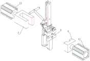
图2为本发明实施例1的PCB板件夹具另一角度的结构示意图。FIG. 2 is a structural schematic diagram of another angle of the PCB board fixture according to
图3为本发明实施例2的PCB板件夹具的结构示意图。FIG. 3 is a schematic structural diagram of a PCB board fixture according to
图4为本发明实施例2的PCB板件夹具另一角度的结构示意图。FIG. 4 is a structural schematic diagram of another angle of the PCB board fixture according to
图5为本发明实施例3的PCB板件夹具的结构示意图。FIG. 5 is a schematic structural diagram of a PCB board fixture according to
图6为本发明实施例4的PCB板件夹具的结构示意图。FIG. 6 is a schematic structural view of a PCB board fixture according to
图7为本发明实施例5的夹具稳定机构的结构示意图。Fig. 7 is a schematic structural view of the fixture stabilization mechanism according to
图8为本发明实施例5的夹具稳定机构另一角度的结构示意图。Fig. 8 is a structural schematic diagram of another angle of the clamp stabilization mechanism according to
图9为本发明实施例6的夹具稳定机构的结构示意图。FIG. 9 is a schematic structural view of the fixture stabilization mechanism according to
图10为本发明实施例6的夹具稳定机构另一角度的结构示意图。Fig. 10 is a structural schematic diagram of another angle of the clamp stabilization mechanism according to
图11为本发明实施例7的夹具稳定机构夹紧时的示意图。Fig. 11 is a schematic diagram of the clamp stabilization mechanism of
图12为本发明实施例7的夹具稳定机构松开时的示意图。Fig. 12 is a schematic diagram when the clamp stabilization mechanism of
图13为对称形PCB板件夹具的结构示意图;Fig. 13 is a structural schematic diagram of a symmetrical PCB board fixture;
图14为本发明实施例8的板件夹具的结构示意图;Fig. 14 is a schematic structural view of a panel fixture according to
图15为本发明实施例8的板件夹具另一角度的结构示意图;Fig. 15 is a structural schematic diagram of another angle of the panel fixture according to
图16为本发明实施例9的板件夹具的结构示意图;Fig. 16 is a schematic structural view of a panel fixture according to
图17为本发明实施例10的板件夹具的结构示意图。Fig. 17 is a schematic structural diagram of a panel clamp according to
具体实施方式Detailed ways
为了让本发明的上述和其它目的、特征及优点能更明显,下文特举本发明实施例,并配合所附图示,做详细说明如下。In order to make the above and other objects, features and advantages of the present invention more apparent, the following specifically cites the embodiments of the present invention, together with the accompanying drawings, for a detailed description as follows.
实施例1Example 1
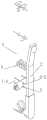
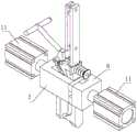
如图1和图2所示,本实施例的PCB板件夹具包括固定臂1(第一夹臂)、通过铰轴与固定臂1相连的活动臂2(第二夹臂),活动臂2可绕铰轴(未图示)转动,从而和固定臂1夹紧或松开。在固定臂1和活动臂2之间设置有压紧弹簧3,压紧弹簧3的一端抵在固定臂1上、另一端抵在活动臂2上,为固定臂1和活动臂2提供使两者相互夹紧的作用力,从而夹具可以处于夹紧的状态。施加于活动臂2上的外力克服压紧弹簧3的弹力时可将夹具打开。压紧弹簧3位于铰轴的上方。As shown in Figures 1 and 2, the PCB board fixture of this embodiment includes a fixed arm 1 (first clamp arm), a movable arm 2 (second clamp arm) connected to the
固定臂1上具有固定臂铰轴连接部1-1,固定臂铰轴连接部1-1从固定臂1上向活动臂2延伸,活动臂2上具有活动臂铰轴连接部2-1,活动臂铰轴连接部2-1从活动臂2向固定臂延伸,固定臂铰轴连接部1-1和活动臂铰轴连接部2-1通过铰轴相连。在铰轴的两侧分别设置有夹具稳定突部4,夹具稳定突部4沿平行于铰轴的轴向的方向突出于固定臂1夹具)的两侧。夹具稳定突部4可直接或间接与固定臂1相连,本实施例的夹具稳定突部4设置于固定臂铰轴连接部1-1上,在其他的实施例中,如果活动臂铰轴连接部2-1位于固定臂铰轴连接部1-1的外侧,夹具稳定突部4也可以设置于活动臂铰轴连接部2-1上,通过活动臂铰轴连接部2-1间接和固定臂铰轴连接部1-1相连。The
实施例2Example 2
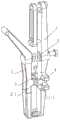
如图3和图4所示,本实施例和实施例1不同的地方在于,本实施例的夹具稳定突部4和固定臂1连为一体,夹具稳定突部4设置于固定臂1上。固定臂铰轴连接部1-1和活动臂铰轴连接部2-1通过铰轴5相连。夹具稳定突部4设置于固定臂1的中下部,位于压紧弹簧3的下方,且设置于铰轴5的附近,即铰轴5在固定臂1所在平面(和压紧弹簧的轴线相垂直的平面)上的投影位于夹具稳定突部4在固定臂所在平面上的投影范围内。As shown in FIG. 3 and FIG. 4 , the difference between this embodiment and
实施例3Example 3
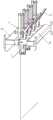
如图5所示,本实施例和实施例1、2不同的地方在于:本实施例PCB板件夹具为自锁型夹具,在夹具上设置有锁紧机构6,压紧弹簧作用于锁紧机构6上。本实施例和常规的自锁型夹具相比,在固定臂1上设置了夹具稳定突部4,夹具稳定突部4通过螺纹紧固件与固定臂1相连。As shown in Figure 5, the difference between this embodiment and
实施例4Example 4
如图6所示,本实施例和实施例3不同的地方在于,本实施例的夹具稳定突部4和固定臂1之间通过焊接的方式相连。As shown in FIG. 6 , the difference between this embodiment and
实施例5Example 5
参照图7和图8,本实施例提供了一种应用于前述实施例的PCB板件夹具的夹具稳定机构,下面以应用于实施例1的PCB板件夹具为例对夹具稳定机构的结构进行说明。PCB板件夹具悬挂于PCB板电镀线的铜扁(未图示)上,固定臂1通过螺纹紧固件或焊接的方式和铜扁(板件挂架)相连,铜扁上设置有多个PCB板件夹具。Referring to Fig. 7 and Fig. 8, the present embodiment provides a fixture stabilizing mechanism applied to the PCB board fixture of the foregoing embodiment, and the structure of the fixture stabilizing mechanism is described below taking the PCB board fixture applied in
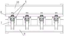
夹具稳定机构包括第一稳定突部夹紧部7、第二稳定突部夹紧部8、第一夹紧部安装架9以及第二夹紧部安装架10。第一稳定突部夹紧部7和第二稳定突部夹紧部8相对设置,两者间可在水平方向上相互移动,从而夹紧PCB板件夹具上的夹具稳定突部4。本实施例的第一稳定突部夹紧部7和第二稳定突部夹紧部8均呈U形,且为对称结构。第一稳定突部夹紧部7设置于第一夹紧部安装架9上,第二稳定突部夹紧部8设置于第二夹紧部安装架9上。第一夹紧部安装架9由移动驱动单元(未图示)驱动可在水平方向上移动,第二夹紧部安装架10同样由移动驱动单元(未图示)驱动可在水平方向上移动,两者可向着相互靠近或相互远离的方向平移,从而使第一稳定突部夹紧部7和第二稳定突部夹紧部8夹紧PCB板件夹具上的夹具稳定突部4或松开PCB板件夹具上的夹具稳定突部4,当夹紧PCB板件夹具上的夹具稳定突部4时,可以对PCB板件夹具起到稳定的作用。夹紧部安装架上可同时设置多个稳定突部夹紧部,从而同时稳定多个PCB板件夹具,保持这些PCB板件夹具位置的一致性。第一、第二夹紧部安装架可由同一个移动驱动单元通过同步传动结构控制移动,也可以分别由不同的移动驱动单元控制移动,移动驱动单元可以是气缸、电机、推杆等常规的机械驱动单元。The clamp stabilizing mechanism includes a first stabilizing
实施例6Example 6
如图9和图10所示,本实施例和实施例5不同的地方在于,本实施例的第一稳定突部夹紧部7呈U形,第二稳定突部夹紧部8为平板结构,可应用于实施例应用于实施例2-4的PCB板件夹具。第一稳定突部夹紧部7设置于第一夹紧部安装架9上,第二稳定突部夹紧部8设置于第二夹紧部安装架9上。第一夹紧部安装架9由移动驱动单元(未图示)驱动可在水平方向上移动,第二夹紧部安装架10同样由移动驱动单元(未图示)驱动可在水平方向上移动,两者可向着相互靠近或相互远离的方向平移,从而使第一稳定突部夹紧部7和第二稳定突部夹紧部8夹紧PCB板件夹具上的夹具稳定突部4或松开PCB板件夹具上的夹具稳定突部4,当夹紧PCB板件夹具上的夹具稳定突部4时,可以对PCB板件夹具起到稳定的作用。As shown in Figure 9 and Figure 10, the difference between this embodiment and
实施例7Example 7
如图11和图12所示,本实施例和实施例5不同的地方在于,本实施例的第一稳定突部夹紧部7和第二稳定突部夹紧部8虽然都呈U形,但两者的长度不一样,可应用于实施例应用于实施例2-4的PCB板件夹具。同时,第一稳定突部夹紧部7和第二稳定突部夹紧部8均直接和各自的移动驱动单元11相连,本实施例的移动驱动单元11为气缸。As shown in Figure 11 and Figure 12, the difference between this embodiment and
前述实施例的板件夹具都是非对称偏开型夹具,即第一夹臂和第二夹具不是对称结构,其中一个夹臂相对固定,另一个夹臂相对固定的夹臂转动,从而打开或关闭,但也可用于如图13所示的对称性夹具中,夹具稳定突部4设置在和第一夹臂和第二夹臂相连的铰轴连接部Q上,实施例5的夹具稳定机构可用于此类对称形板件夹具上。The panel clamps in the foregoing embodiments are all asymmetrical offset clamps, that is, the first clamp arm and the second clamp are not symmetrical in structure, one of the clamp arms is relatively fixed, and the other clamp arm rotates relative to the fixed clamp arm, thereby opening or closing , but it can also be used in a symmetrical clamp as shown in Figure 13, the
实施例8Example 8
为了方便板件夹具在铜扁上的安装定位,板件夹具上还可以包括夹具定位组件,夹具定位组件设置于铜扁上,用于实现板件夹具在铜扁上的安装定位。如图14和图15所示,本实施例的夹具定位组件包括和第一夹臂1相对设置的铜扁压板12,以及设置于铜扁压板12上的夹具定位销13,在铜扁压板12上加工有供夹具定位销13穿过的定位销孔(未图示)。铜扁压板12通过连接螺栓14和第一夹臂1相连,本实施例的连接螺栓14设置于铜扁压板12的上部和下部,铜扁压板12和第一夹臂1上设置有位置相对应的螺纹孔(未图示),连接螺栓14穿过铜扁压板12和第一夹臂1上的螺纹孔,将铜扁压板12和第一夹臂1连接在一起,从而铜扁压板12和第一夹臂1都设置于铜扁100上。本实施例的定位销孔位于铜扁压板12上下两个螺纹孔之间,夹具定位销13穿过定位销孔后,压紧在位于铜扁压板12和第一夹臂1之间的铜扁100上,从而实现板件夹具在铜扁100上的定位。In order to facilitate the installation and positioning of the board fixture on the copper flat, the board fixture may also include a fixture positioning component, which is arranged on the copper flat to realize the installation and positioning of the board fixture on the copper flat. As shown in Fig. 14 and Fig. 15, the clamp positioning assembly of this embodiment includes a copper
实施例9Example 9
如图16所示,本实施例和实施例8不同的地方在于:本实施例的夹具定位组件包括一对L形的定位夹板15,定位夹板15通过螺钉或螺栓等紧固件(未标号)固定在铜扁100上,定位夹板15的截面形状为L形,两个定位夹板15分别位于板件夹具的第一夹臂1的两侧,将第一夹臂1夹在中间,从而实现板件夹具在铜扁100上的定位。As shown in Figure 16, the difference between this embodiment and
实施例10Example 10
如图17所示,本实施例和实施例9及实施例10不同的地方在于:本实施例的铜扁100为水平设置,而不是竖直设置。本实施例的夹具定位组件为穿过铜扁100的定位连接螺栓16,板件夹具具有水平设置的安装板17,安装板17和铜扁100上加工有供定位连接螺栓16穿过的装配孔(未图示),定位连接螺栓16穿过安装板17及铜扁100后,和螺母(未标号)相配合,实现板件夹具在铜扁100上的安装及定位。As shown in FIG. 17 , the difference between this embodiment and
本说明书中各个部分采用递进的方式描述,每个部分重点说明的都是与其它部分的不同之处,各个部分之间相同或相似部分互相参见即可。对所公开的实施例的上述说明,使本领域专业技术人员能够实现或使用本发明。对这些实施例的多种修改对本领域的专业技术人员来说将是显而易见的,本文中所定义的一般原理可以在不脱离本发明的精神或范围的情况下,在其它实施例中实现。因此,本发明将不会被限制于本文所示的实施例,而是要符合与本文所公开的原理和新颖特点相一致的最宽范围。Each part in this specification is described in a progressive manner, and each part focuses on the difference from other parts, and the same or similar parts of each part can be referred to each other. The above description of the disclosed embodiments is provided to enable any person skilled in the art to make or use the invention. Various modifications to these embodiments will be readily apparent to those skilled in the art, and the general principles defined herein may be implemented in other embodiments without departing from the spirit or scope of the invention. Therefore, the present invention will not be limited to the embodiments shown herein, but is to be accorded the widest scope consistent with the principles and novel features disclosed herein.
Claims (11)
Applications Claiming Priority (2)
| Application Number | Priority Date | Filing Date | Title |
|---|---|---|---|
| CN2021232775396 | 2021-12-20 | ||
| CN202123277539 | 2021-12-20 |
Publications (1)
| Publication Number | Publication Date |
|---|---|
| CN116288623Atrue CN116288623A (en) | 2023-06-23 |
Family
ID=86784001
Family Applications (2)
| Application Number | Title | Priority Date | Filing Date |
|---|---|---|---|
| CN202223395352.0UActiveCN219689913U (en) | 2021-12-20 | 2022-12-16 | PCB (printed circuit board) clamp and clamp stabilizing mechanism |
| CN202211626260.0APendingCN116288623A (en) | 2021-12-20 | 2022-12-16 | PCB (printed circuit board) clamp and clamp stabilizing mechanism |
Family Applications Before (1)
| Application Number | Title | Priority Date | Filing Date |
|---|---|---|---|
| CN202223395352.0UActiveCN219689913U (en) | 2021-12-20 | 2022-12-16 | PCB (printed circuit board) clamp and clamp stabilizing mechanism |
Country Status (1)
| Country | Link |
|---|---|
| CN (2) | CN219689913U (en) |
Families Citing this family (1)
| Publication number | Priority date | Publication date | Assignee | Title |
|---|---|---|---|---|
| CN219689913U (en)* | 2021-12-20 | 2023-09-15 | 陕西中土重工机械有限公司 | PCB (printed circuit board) clamp and clamp stabilizing mechanism |
Citations (12)
| Publication number | Priority date | Publication date | Assignee | Title |
|---|---|---|---|---|
| JP3162603U (en)* | 2010-06-25 | 2010-09-09 | ツバキ山久チエイン株式会社 | Elastic grip for grip chain |
| JP3176980U (en)* | 2012-04-28 | 2012-07-12 | 丸仲工業株式会社 | Clamping jig for thin plate-like workpieces in horizontal transfer plating processing equipment |
| CN203333801U (en)* | 2013-07-24 | 2013-12-11 | 亿鸿环保机械(苏州)有限公司 | Clamp |
| CN103737514A (en)* | 2013-12-26 | 2014-04-23 | 昆山福易雅自动化科技有限公司 | Product clamping device |
| JP2016108601A (en)* | 2014-12-04 | 2016-06-20 | 株式会社オジックテクノロジーズ | Jig and jig production method |
| JP2016131052A (en)* | 2015-01-14 | 2016-07-21 | アルパイン株式会社 | Disk clamp mechanism |
| CN108502719A (en)* | 2018-05-22 | 2018-09-07 | 微山宏瑞电力科技有限公司 | A kind of firm stone tongs of electric pole |
| CN210367984U (en)* | 2019-07-05 | 2020-04-21 | 天津精工华晖制版技术开发有限公司 | Stabilising arrangement for electroplate |
| CN210367961U (en)* | 2019-07-11 | 2020-04-21 | 天津市津川精密电子有限公司 | Feeding clamp for anodic oxidation of aluminum profile |
| CN212834095U (en)* | 2020-03-30 | 2021-03-30 | 陕西中土重工机械有限公司 | Automatic board loading and unloading device for PCB (printed circuit board) electroplating line |
| CN219689913U (en)* | 2021-12-20 | 2023-09-15 | 陕西中土重工机械有限公司 | PCB (printed circuit board) clamp and clamp stabilizing mechanism |
| CN219689915U (en)* | 2021-12-20 | 2023-09-15 | 陕西中土重工机械有限公司 | Electroplating suspension bracket |
- 2022
- 2022-12-16CNCN202223395352.0Upatent/CN219689913U/enactiveActive
- 2022-12-16CNCN202211626260.0Apatent/CN116288623A/enactivePending
Patent Citations (12)
| Publication number | Priority date | Publication date | Assignee | Title |
|---|---|---|---|---|
| JP3162603U (en)* | 2010-06-25 | 2010-09-09 | ツバキ山久チエイン株式会社 | Elastic grip for grip chain |
| JP3176980U (en)* | 2012-04-28 | 2012-07-12 | 丸仲工業株式会社 | Clamping jig for thin plate-like workpieces in horizontal transfer plating processing equipment |
| CN203333801U (en)* | 2013-07-24 | 2013-12-11 | 亿鸿环保机械(苏州)有限公司 | Clamp |
| CN103737514A (en)* | 2013-12-26 | 2014-04-23 | 昆山福易雅自动化科技有限公司 | Product clamping device |
| JP2016108601A (en)* | 2014-12-04 | 2016-06-20 | 株式会社オジックテクノロジーズ | Jig and jig production method |
| JP2016131052A (en)* | 2015-01-14 | 2016-07-21 | アルパイン株式会社 | Disk clamp mechanism |
| CN108502719A (en)* | 2018-05-22 | 2018-09-07 | 微山宏瑞电力科技有限公司 | A kind of firm stone tongs of electric pole |
| CN210367984U (en)* | 2019-07-05 | 2020-04-21 | 天津精工华晖制版技术开发有限公司 | Stabilising arrangement for electroplate |
| CN210367961U (en)* | 2019-07-11 | 2020-04-21 | 天津市津川精密电子有限公司 | Feeding clamp for anodic oxidation of aluminum profile |
| CN212834095U (en)* | 2020-03-30 | 2021-03-30 | 陕西中土重工机械有限公司 | Automatic board loading and unloading device for PCB (printed circuit board) electroplating line |
| CN219689913U (en)* | 2021-12-20 | 2023-09-15 | 陕西中土重工机械有限公司 | PCB (printed circuit board) clamp and clamp stabilizing mechanism |
| CN219689915U (en)* | 2021-12-20 | 2023-09-15 | 陕西中土重工机械有限公司 | Electroplating suspension bracket |
Non-Patent Citations (1)
| Title |
|---|
| 汪佑思;: "PCB电路印刷基板卡位数控加工夹具设计", 模具工业, no. 03, 15 March 2013 (2013-03-15)* |
Also Published As
| Publication number | Publication date |
|---|---|
| CN219689913U (en) | 2023-09-15 |
Similar Documents
| Publication | Publication Date | Title |
|---|---|---|
| CN105568352B (en) | One kind plating folder | |
| CN116288623A (en) | PCB (printed circuit board) clamp and clamp stabilizing mechanism | |
| CN108320671B (en) | Connection structure and display device | |
| CN205313696U (en) | Go up unloading and open clamp device | |
| CN108167718A (en) | Flap seat and Fast Installation structure | |
| CN107570945A (en) | A kind of circuit board welding clamp | |
| CN104236583A (en) | Novel high-efficiency gyro alignment calibration device | |
| CN212910253U (en) | Chip mounter PCB board mounting fixture | |
| CN207757645U (en) | The card taking clip claw mechanism of card dispatcher | |
| CN116056364A (en) | Welding fixing device for double-sided PCB circuit board | |
| CN205119378U (en) | Polar plate assembly and air purifier | |
| CN209344688U (en) | Indoor electric wire wiring groove mounting structure | |
| KR101503041B1 (en) | Plating Rack | |
| CN208196769U (en) | A kind of terminal-collecting machine fixed mechanism of terminal-collecting machine analog platform | |
| CN206899048U (en) | Adjusting and clamping device for a fixture | |
| CN208127059U (en) | A kind of mounting base of quick despatch microswitch | |
| CN209224100U (en) | Cable fixing structure and robot with same | |
| CN220338350U (en) | Wall washer lamp | |
| CN208867179U (en) | A module automatic assembly machine feeding mechanism | |
| CN221742336U (en) | Medium voltage switchgear with door interlock | |
| CN220218210U (en) | Car side wall anchor clamps switch structure | |
| CN221774035U (en) | A clamp for fully automatic conveyor | |
| CN218412661U (en) | Probe connecting structure for PCB detection | |
| CN206020474U (en) | Pcb board fixed structure and detecting system | |
| CN223363752U (en) | Automobile wiring harness distribution frame |
Legal Events
| Date | Code | Title | Description |
|---|---|---|---|
| PB01 | Publication | ||
| PB01 | Publication | ||
| SE01 | Entry into force of request for substantive examination | ||
| SE01 | Entry into force of request for substantive examination |