CN116280682A - container with lid - Google Patents
container with lidDownload PDFInfo
- Publication number
- CN116280682A CN116280682ACN202211655084.3ACN202211655084ACN116280682ACN 116280682 ACN116280682 ACN 116280682ACN 202211655084 ACN202211655084 ACN 202211655084ACN 116280682 ACN116280682 ACN 116280682A
- Authority
- CN
- China
- Prior art keywords
- container
- recess
- lid
- ventilation
- cover
- Prior art date
- Legal status (The legal status is an assumption and is not a legal conclusion. Google has not performed a legal analysis and makes no representation as to the accuracy of the status listed.)
- Pending
Links
Images


Classifications
- B—PERFORMING OPERATIONS; TRANSPORTING
- B65—CONVEYING; PACKING; STORING; HANDLING THIN OR FILAMENTARY MATERIAL
- B65D—CONTAINERS FOR STORAGE OR TRANSPORT OF ARTICLES OR MATERIALS, e.g. BAGS, BARRELS, BOTTLES, BOXES, CANS, CARTONS, CRATES, DRUMS, JARS, TANKS, HOPPERS, FORWARDING CONTAINERS; ACCESSORIES, CLOSURES, OR FITTINGS THEREFOR; PACKAGING ELEMENTS; PACKAGES
- B65D53/00—Sealing or packing elements; Sealings formed by liquid or plastics material
- B65D53/02—Collars or rings
- B—PERFORMING OPERATIONS; TRANSPORTING
- B65—CONVEYING; PACKING; STORING; HANDLING THIN OR FILAMENTARY MATERIAL
- B65D—CONTAINERS FOR STORAGE OR TRANSPORT OF ARTICLES OR MATERIALS, e.g. BAGS, BARRELS, BOTTLES, BOXES, CANS, CARTONS, CRATES, DRUMS, JARS, TANKS, HOPPERS, FORWARDING CONTAINERS; ACCESSORIES, CLOSURES, OR FITTINGS THEREFOR; PACKAGING ELEMENTS; PACKAGES
- B65D41/00—Caps, e.g. crown caps or crown seals, i.e. members having parts arranged for engagement with the external periphery of a neck or wall defining a pouring opening or discharge aperture; Protective cap-like covers for closure members, e.g. decorative covers of metal foil or paper
- B65D41/02—Caps or cap-like covers without lines of weakness, tearing strips, tags, or like opening or removal devices
- B65D41/04—Threaded or like caps or cap-like covers secured by rotation
- B65D41/0435—Threaded or like caps or cap-like covers secured by rotation with separate sealing elements
- B65D41/0442—Collars or rings
- B—PERFORMING OPERATIONS; TRANSPORTING
- B65—CONVEYING; PACKING; STORING; HANDLING THIN OR FILAMENTARY MATERIAL
- B65D—CONTAINERS FOR STORAGE OR TRANSPORT OF ARTICLES OR MATERIALS, e.g. BAGS, BARRELS, BOTTLES, BOXES, CANS, CARTONS, CRATES, DRUMS, JARS, TANKS, HOPPERS, FORWARDING CONTAINERS; ACCESSORIES, CLOSURES, OR FITTINGS THEREFOR; PACKAGING ELEMENTS; PACKAGES
- B65D51/00—Closures not otherwise provided for
- B65D51/16—Closures not otherwise provided for with means for venting air or gas
- B65D51/1633—Closures not otherwise provided for with means for venting air or gas whereby venting occurs by automatic opening of the closure, container or other element
- B65D51/1644—Closures not otherwise provided for with means for venting air or gas whereby venting occurs by automatic opening of the closure, container or other element the element being a valve
- B65D51/1655—Closures not otherwise provided for with means for venting air or gas whereby venting occurs by automatic opening of the closure, container or other element the element being a valve formed by an elastic band closing an opening in a tubular part of the closure encircled by said band
- B—PERFORMING OPERATIONS; TRANSPORTING
- B65—CONVEYING; PACKING; STORING; HANDLING THIN OR FILAMENTARY MATERIAL
- B65D—CONTAINERS FOR STORAGE OR TRANSPORT OF ARTICLES OR MATERIALS, e.g. BAGS, BARRELS, BOTTLES, BOXES, CANS, CARTONS, CRATES, DRUMS, JARS, TANKS, HOPPERS, FORWARDING CONTAINERS; ACCESSORIES, CLOSURES, OR FITTINGS THEREFOR; PACKAGING ELEMENTS; PACKAGES
- B65D51/00—Closures not otherwise provided for
- B65D51/16—Closures not otherwise provided for with means for venting air or gas
- B65D51/1672—Closures not otherwise provided for with means for venting air or gas whereby venting occurs by manual actuation of the closure or other element
Landscapes
- Engineering & Computer Science (AREA)
- Mechanical Engineering (AREA)
- Closures For Containers (AREA)
- Filling Or Discharging Of Gas Storage Vessels (AREA)
Abstract
Description
Translated fromChinese技术领域technical field
本发明涉及带盖容器。The present invention relates to containers with lids.
背景技术Background technique
例如,存在一种带盖容器,其采用了使用内盖以及外盖来对设置于容器主体的开口部进行密闭的构造(例如,参照下述专利文献1。)。For example, there is a container with a lid that has a structure that seals an opening provided in a container main body using an inner lid and an outer lid (for example, refer to Patent Document 1 below).
具体而言,这样的带盖容器具备:容器主体,其在上端部设置有开口部;内盖,其在从开口部嵌入了容器主体的内侧的状态下关闭开口部;止水衬垫,其在安装于内盖的状态下对容器主体与内盖之间进行密闭;以及外盖,其在从外侧覆盖了开口部的状态下通过旋合而装配于容器主体。此外,带盖容器成为设置于外盖的闭栓衬垫(栓体)关闭设置于内盖的空气孔(通气孔)的构造。Specifically, such a container with a lid includes: a container main body provided with an opening at an upper end; an inner lid that closes the opening while being fitted into the inside of the container main body from the opening; The container body is sealed between the container body and the inner cap in a state attached to the inner cap, and the outer cap is screwed and assembled to the container body in a state covering the opening from the outside. In addition, the container with a lid has a structure in which a plug-closing packing (plug body) provided on the outer lid closes an air hole (vent hole) provided on the inner lid.
在这样的带盖容器中,在将外盖装配于容器主体时,闭栓衬垫与内盖抵接,由此限制内盖向上侧的移动。另外,在带盖容器中,在从容器主体取下外盖时,闭栓衬垫对空气孔的关闭被解除。由此,即便在容器主体内的压力降低(成为负压)的情况下,由于在从容器主体取下外盖时外部空气通过空气孔导入,所以容器主体内的压力也与大气压相同。因此,内盖不被拉向容器主体的内侧,从而能够将内盖从容器主体容易地取下。In such a container with a lid, when the outer lid is attached to the container body, the stopper gasket abuts on the inner lid, thereby restricting the upward movement of the inner lid. In addition, in the container with a lid, when the outer lid is removed from the container main body, the closing gasket for the air hole is released. Thus, even when the pressure inside the container body decreases (becomes a negative pressure), since outside air is introduced through the air hole when the outer cover is removed from the container body, the pressure inside the container body is equal to atmospheric pressure. Therefore, the inner cap is not pulled toward the inner side of the container body, and the inner cap can be easily removed from the container body.
专利文献1:日本专利第5494717号公报Patent Document 1: Japanese Patent No. 5494717
然而,在上述的现有的带盖容器中,采用使用内盖以及外盖对设置于容器主体的开口部进行密闭的构造,由此不仅构造复杂化,还存在成本因部件数量的增加而增大的问题。However, in the above-mentioned conventional container with a lid, the opening portion provided in the container body is sealed using the inner lid and the outer lid, which not only complicates the structure, but also increases the cost due to the increase in the number of parts. Big question.
发明内容Contents of the invention
本发明是鉴于这样的现有的状况而提出的,目的在于提供一种带盖容器,其具有低成本且简便的构造,并且相对于容器主体内的压力变化能够将盖体从容器主体容易且安全地取下。The present invention is made in view of such existing conditions, and an object thereof is to provide a container with a lid which has a low-cost and simple structure, and which can easily remove the lid from the container body in response to pressure changes in the container body. Remove safely.
为了实现上述目的,本发明提供以下的方案。In order to achieve the above objects, the present invention provides the following solutions.
〔1〕一种带盖容器,其特征在于,具备:[1] A container with a lid, characterized in that it has:
容器主体,该容器主体的上端部开口;a container body, the upper end of which is open;
盖体,该盖体通过旋合而装卸自如地安装于上述容器主体,由此对上述容器主体的上端开口部进行开闭;以及a lid body, which is detachably attached to the container body by screwing, thereby opening and closing the upper end opening of the container body; and
止水衬垫,该止水衬垫在上述盖体关闭了上述容器主体的上端开口部的状态下,与上述容器主体的上端部遍及整周紧贴,并且对上述容器主体与上述盖体之间进行密闭,A water-stop gasket that is in close contact with the upper end of the container body over the entire circumference in a state where the lid closes the upper end opening of the container body, and that seals the gap between the container body and the lid. room is sealed,
上述盖体具有:周壁部,该周壁部与上述容器主体的外周面对置;顶壁部,该顶壁部对上述周壁部的上部进行关闭;肋壁,该肋壁与上述周壁部的内周面对置,并且从上述顶壁部的下表面遍及整周地突出;槽部,该槽部形成于上述周壁部与上述肋壁之间;第1通气用凹部,该第1通气用凹部使上述槽部的底面的一部分沿着径向凹陷而成;以及第2通气用凹部,该第2通气用凹部使上述肋壁的一部分沿着上下方向凹陷而成,The cover body has: a peripheral wall portion facing the outer peripheral surface of the container body; a top wall portion closing the upper portion of the peripheral wall portion; The peripheral surfaces face each other and protrude from the lower surface of the top wall portion over the entire circumference; the groove portion is formed between the peripheral wall portion and the rib wall; the first ventilation concave portion is the first ventilation concave portion a part of the bottom surface of the groove portion is dented in the radial direction; and a second ventilation recess is formed by denting a part of the rib wall in the vertical direction,
上述止水衬垫具有与上述槽部嵌合的第1弹性部、和设置有供上述肋壁嵌合的嵌合凹部的第2弹性部,上述止水衬垫通过嵌合而装卸自如地安装于上述盖体的内侧。The waterproof gasket has a first elastic portion fitted into the groove, and a second elastic portion provided with a fitting recess for fitting the rib wall, and the waterproof gasket is detachably attached by fitting. on the inside of the cover.
〔2〕一种带盖容器,其特征在于,具备:[2] A container with a lid, characterized in that it has:
容器主体,该容器主体的上端部开口;a container body, the upper end of which is open;
盖体,该盖体通过旋合而装卸自如地安装于上述容器主体,由此对上述容器主体的上端开口部进行开闭;以及a lid body, which is detachably attached to the container body by screwing, thereby opening and closing the upper end opening of the container body; and
止水衬垫,该止水衬垫在上述盖体关闭了上述容器主体的上端开口部的状态下,与上述容器主体的上端部遍及整周紧贴,并且对上述容器主体与上述盖体之间进行密闭,A water-stop gasket that is in close contact with the upper end of the container body over the entire circumference in a state where the lid closes the upper end opening of the container body, and that seals the gap between the container body and the lid. room is sealed,
上述盖体具有:周壁部,该周壁部与上述容器主体的外周面对置;顶壁部,该顶壁部对上述周壁部的上部进行关闭;肋壁,该肋壁与上述周壁部的内周面对置,并且从上述顶壁部的下表面遍及整周地突出;以及槽部,该槽部形成于上述周壁部与上述肋壁之间,The cover body has: a peripheral wall portion facing the outer peripheral surface of the container body; a top wall portion closing the upper portion of the peripheral wall portion; The peripheral surfaces face each other and protrude from the lower surface of the top wall portion over the entire circumference; and a groove portion is formed between the peripheral wall portion and the rib wall,
上述止水衬垫具有:第1弹性部,该第1弹性部与上述槽部嵌合;第2弹性部,该第2弹性部设置有供上述肋壁嵌合的嵌合凹部;第1通气用凹部,该第1通气用凹部使上述第1弹性部中的与上述槽部的底面对置的面的一部分沿着径向凹陷而成;以及第2通气用凹部,该第2通气用凹部使上述第2弹性部中的与上述肋壁对置的面的一部分沿着上下方向凹陷而成,上述止水衬垫通过嵌合而装卸自如地安装于上述盖体的内侧。The above-mentioned waterproof gasket has: a first elastic part fitted into the groove; a second elastic part provided with a fitting recess for fitting the rib wall; a first air vent A concave portion, the first ventilation concave portion is formed by denting a part of the surface of the first elastic portion facing the bottom surface of the groove portion in the radial direction; and a second ventilation concave portion, the second ventilation. The recess is formed by denting a part of the surface of the second elastic portion facing the rib wall in the vertical direction, and the waterproof gasket is detachably attached to the inside of the cover by fitting.
〔3〕根据上述〔1〕或〔2〕记载的带盖容器,其特征在于,在上述容器主体内的压力上升或者降低时,上述止水衬垫的一部分弹性变形,并且通过上述第1通气用凹部、上述第2通气用凹部以及上述嵌合凹部的一部分,使外部与上述容器主体的内部通气。[3] The container with a lid according to the above [1] or [2], wherein when the pressure in the container body increases or decreases, a part of the water-stop packing elastically deforms, and the first ventilation The outside and the inside of the container main body are ventilated through the concave portion, the second ventilation concave portion, and a part of the fitting concave portion.
〔4〕根据上述〔1〕或〔2〕记载的带盖容器,其特征在于,上述第2通气用凹部设置于与上述第1通气用凹部在周向重叠的位置。[4] The container with a lid according to the above [1] or [2], wherein the second venting recess is provided at a position overlapping the first venting recess in the circumferential direction.
〔5〕根据上述〔1〕或〔2〕记载的带盖容器,其特征在于,上述第1通气用凹部与上述第2通气用凹部连续地设置。[5] The container with a lid according to the above [1] or [2], wherein the first venting recess and the second venting recess are provided continuously.
〔6〕根据上述〔1〕或〔2〕记载的带盖容器,其特征在于,上述止水衬垫具有第3弹性部,上述第3弹性部隔着上述嵌合凹部位于与上述第1弹性部相反的一侧。[6] The container with a lid according to the above [1] or [2], wherein the waterproof gasket has a third elastic portion, and the third elastic portion is located opposite to the first elastic portion via the fitting recess. the opposite side of the department.
〔7〕根据上述〔1〕或〔2〕记载的带盖容器,其特征在于,上述第1通气用凹部以及上述第2通气用凹部分别设置于周向的多个部位。[7] The container with a lid according to the above [1] or [2], wherein the first venting recess and the second venting recess are respectively provided at a plurality of positions in the circumferential direction.
〔8〕根据上述〔1〕或〔2〕记载的带盖容器,其特征在于,上述第1通气用凹部形成为比上述第2通气用凹部宽度宽。[8] The container with a lid according to the above [1] or [2], wherein the first venting recess is formed wider than the second venting recess.
〔9〕根据上述〔1〕或〔2〕记载的带盖容器,其特征在于,上述盖体具有内螺纹部,该内螺纹部设置于上述周壁部的内周面,上述容器主体具有外螺纹部,该外螺纹部设置于与上述周壁部对置的外周面,通过上述内螺纹部与上述外螺纹部的旋合,而将上述盖体装卸自如地安装于上述容器主体。[9] The container with a lid according to the above [1] or [2], wherein the lid body has an internal thread portion provided on the inner peripheral surface of the peripheral wall portion, and the container body has an external thread. The external thread portion is provided on the outer peripheral surface facing the peripheral wall portion, and the lid body is detachably attached to the container body by screwing the internal thread portion and the external thread portion.
如以上那样,根据本发明,能够提供一种带盖容器,其具有低成本且简便的构造,并且相对于容器主体内的压力变化能够将盖体从容器主体容易且安全地取下。As described above, according to the present invention, it is possible to provide a container with a lid which has a low-cost and simple structure and which can easily and safely remove the lid from the container body against pressure changes in the container body.
附图说明Description of drawings
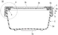
图1是表示本发明的第1实施方式所涉及的带盖容器的结构的分解立体图。Fig. 1 is an exploded perspective view showing the structure of a container with a lid according to a first embodiment of the present invention.
图2是表示带盖容器的相对于容器主体安装了盖体的状态的剖视图。Fig. 2 is a cross-sectional view showing a state where a lid body is attached to a container body of the container with a lid.
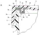
图3是对图2中所示的包围部分A进行了放大的带盖容器的剖视图。FIG. 3 is an enlarged cross-sectional view of the enclosed portion A shown in FIG. 2 .
图4是表示在盖体的内侧安装了止水衬垫的状态的立体图。Fig. 4 is a perspective view showing a state where a waterproof packing is attached to the inside of the cover.
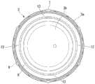
图5是表示盖体的内侧的俯视图。Fig. 5 is a plan view showing the inside of the cover.
图6是对图5中所示的包围部分B进行了放大的盖体的俯视图。FIG. 6 is a plan view of the cover body in which the enclosing portion B shown in FIG. 5 is enlarged.
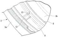
图7是对图5中所示的包围部分B进行了放大的盖体的立体图。FIG. 7 is a perspective view of the cover body in which the enclosing portion B shown in FIG. 5 is enlarged.
图8是在对图2中所示的包围部分A进行了放大的带盖容器的剖视图中,用于对容器主体内的压力降低了时的止水衬垫的变形状态进行说明的图。Fig. 8 is a view for explaining a deformed state of the water-tight packing when the pressure in the container main body is lowered in a cross-sectional view of the container with a lid enlarging the enclosing portion A shown in Fig. 2 .
图9是作为图1所示的带盖容器的变形例,对图2中所示的包围部分A进行了放大的带盖容器的剖视图。FIG. 9 is a cross-sectional view of a closed container shown in FIG. 2 in which the enclosing portion A shown in FIG. 2 is enlarged as a modified example of the covered container shown in FIG. 1 .
图10是作为图1所示的带盖容器的变形例,对图5中所示的包围部分B进行了放大的盖体的立体图。Fig. 10 is a perspective view of a cap body showing an enlarged enclosing portion B shown in Fig. 5 as a modified example of the container with a cap shown in Fig. 1 .
图11是作为图1所示的带盖容器的变形例,表示第2通气用凹部相对于第1通气用凹部位于沿周向移动了90°的位置时的盖体的内侧的俯视图。11 is a plan view showing the inside of the lid when the second venting recess is located at a position shifted by 90° in the circumferential direction from the first venting recess as a modified example of the container with a lid shown in FIG. 1 .
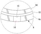
图12是表示本发明的第2实施方式所涉及的带盖容器的结构的分解立体图。Fig. 12 is an exploded perspective view showing the structure of a container with a lid according to a second embodiment of the present invention.
图13是表示带盖容器的相对于容器主体安装了盖体的状态的剖视图。Fig. 13 is a cross-sectional view showing a state in which a lid body is attached to a container body of the container with a lid.
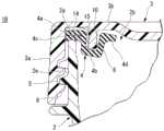
图14是对图13中所示的包围部分C进行了放大的带盖容器的剖视图。FIG. 14 is an enlarged cross-sectional view of a closed portion C shown in FIG. 13 .
图15是表示盖体的内侧的俯视图。Fig. 15 is a plan view showing the inside of the cover.
图16是表示止水衬垫的结构的俯视图。Fig. 16 is a plan view showing the structure of the waterproof gasket.
图17是对图16中所示的包围部分D进行了放大的止水衬垫的俯视图。FIG. 17 is a plan view of the waterproof gasket in which the enclosing portion D shown in FIG. 16 is enlarged.
图18是对图16中所示的包围部分D进行了放大的止水衬垫的立体图。FIG. 18 is a perspective view of the waterproof gasket in which the enclosing portion D shown in FIG. 16 is enlarged.
图19是在对图13中所示的包围部分C进行了放大的带盖容器的剖视图中,用于对容器主体内的压力降低了时的止水衬垫的变形状态进行说明的图。Fig. 19 is a diagram for explaining a deformed state of the water-tight packing when the pressure in the container main body is lowered in a cross-sectional view of the container with a lid enlarging the enclosing portion C shown in Fig. 13 .
附图标记说明Explanation of reference signs
1A、1B...带盖容器;2...容器主体;3...盖体;3a...周壁部;3b...顶壁部;4...止水衬垫;4a...第1弹性部;4b...第2弹性部;4c...弹性凸缘部;4d...第3弹性部;5...外螺纹部;6...内螺纹部;7...突起部;8...肋壁;9...槽部;10...嵌合凹部;11...抓捏片;12...第1通气用凹部;13...第2通气用凹部;14...第1通气用凹部;15...第2通气用凹部。1A, 1B...container with lid; 2...container body; 3...lid; 3a...surrounding wall; 3b...top wall; 4...waterproof gasket; 4a. ..1st elastic part; 4b...2nd elastic part; 4c...elastic flange part; 4d...3rd elastic part; 5...external thread part; 6...internal thread part; 7...protrusion; 8...rib wall; 9...groove; 10...fitting recess; 11...grabbing piece; 12...first ventilating recess; 13.. .The second venting recess; 14...the first venting recess; 15...the second venting recess.
具体实施方式Detailed ways
以下,参照附图,对本发明的实施方式详细地进行说明。Hereinafter, embodiments of the present invention will be described in detail with reference to the drawings.
(第1实施方式)(first embodiment)
首先,作为本发明的第1实施方式,对例如图1~图8所示的带盖容器1A进行说明。First, as a first embodiment of the present invention, for example, a container with a
此外,图1是表示带盖容器1A的结构的分解立体图。图2是表示带盖容器1A的相对于容器主体2安装了盖体3的状态的剖视图。图3是对图2中所示的包围部分A进行了放大的带盖容器1A的剖视图。图4是表示在盖体3的内侧安装了止水衬垫4的状态的立体图。图5是表示盖体3的内侧的俯视图。图6是对图5中所示的包围部分B进行了放大的盖体3的俯视图。图7是对图5中所示的包围部分B进行了放大的盖体3的立体图。图8是在对图2中所示的包围部分A进行了放大的带盖容器1A的剖视图中,用于对容器主体2内的压力降低了时的止水衬垫4的变形状态进行说明的图。In addition, FIG. 1 is an exploded perspective view showing the structure of the container with a
如图1~图3所示,本实施方式的带盖容器1A具备:容器主体2,其上端部2a开口;盖体3,其对容器主体2的上端开口部2b进行开闭;以及止水衬垫4,其对容器主体2与盖体3之间进行密闭。As shown in FIGS. 1 to 3 , a container with a
容器主体2例如由聚丙烯(PP)等耐热性树脂构成,并具有大致圆形状的底部2c、从底部2c的外周以圆筒状立起的躯体部2d以及在躯体部2d的上部侧设置了倾斜面的大致圆筒状的颈口部2e。另外,颈口部2e的上端部作为容器主体2的上端部2a,形成呈圆形状开口的上端开口部2b。The container
如图1~图5所示,盖体3例如由聚丙烯(PP)等耐热性树脂构成,并具有形成为大致圆筒状的周壁部3a、和对周壁部3a的上部进行关闭的顶壁部3b。As shown in FIGS. 1 to 5 , the
盖体3通过旋合而装卸自如地安装于容器主体2。因此,在颈口部2e(容器主体2)的外周面设置有外螺纹部5。另一方面,在与颈口部2e(容器主体2)的外周面对置的周壁部3a(盖体3)的内周面设置有与外螺纹部5旋合的内螺纹部6。The
另外,在周壁部3a(盖体3)的外周面设置有成为防滑部的多个突起部7,该多个突起部7沿上下方向延伸,并且沿周壁部3a的周向等间隔地排列。In addition, on the outer peripheral surface of the
止水衬垫4由例如硅酮橡胶等具有耐热性的大致圆形环状的弹性构件构成。止水衬垫4通过嵌合而装卸自如地安装于盖体3的内侧。The water-
因此,盖体3具有:肋壁8,其与周壁部3a的内周面对置,并且从顶壁部3b的下表面遍及整周呈圆形环状突出;和槽部9,其呈圆形环状形成于周壁部3a与肋壁8之间。Therefore, the
另一方面,止水衬垫4具有:第1弹性部4a,其与槽部9嵌合;第2弹性部4b,其从第1弹性部4a的一端向下方伸长,并设置有供肋壁8嵌合的嵌合凹部10;弹性凸缘部4c,其与第1弹性部4a对置,并且从第2弹性部4b的外周面遍及整周地突出;以及第3弹性部4d,其隔着嵌合凹部10位于与第1弹性部4a相反的一侧(内周侧)。On the other hand, the
止水衬垫4从盖体3取下,由此能够与盖体3单独地进行清洗,从而能够将该止水衬垫4与盖体3之间保持为卫生。另外,在止水衬垫4从第3弹性部4d朝向内侧突出地设置有抓捏片11,该抓捏片11用于从盖体3的内侧容易取下。The
在本实施方式的带盖容器1A中,在将盖体3安装于容器主体2的颈口部2e的状态下、即在盖体3关闭了容器主体2的上端开口部2b的状态下,止水衬垫4的第1弹性部4a弹性变形,并且与盖体3的槽部9的底面遍及整周紧贴,并且止水衬垫4的弹性凸缘部4c弹性变形,并且与容器主体2的上端部2a遍及整周紧贴,由此通过止水衬垫4对容器主体2与盖体3之间进行密闭。In the capped
然而,在本实施方式的带盖容器1A中,如图3、图6以及图7所示,盖体3具有:第1通气用凹部12,其使槽部9的底面的一部分沿着径向凹陷而成;和第2通气用凹部13,其使肋壁8的一部分在与第1通气用凹部12在周向重叠的位置沿着上下方向凹陷而成。However, in the capped
第1通气用凹部12形成为比第2通气用凹部13宽度宽。另外,第2通气用凹部13设置为在与第1通气用凹部12在周向重叠的位置与第1通气用凹部12连续。即,该第2通气用凹部13设置为从肋壁8的前端(下端)凹陷至基端(上端)。The
第1通气用凹部12以及第2通气用凹部13分别设置于周向的多个部位(在本实施方式中为2个部位)。在该情况下,第1通气用凹部12以及第2通气用凹部13优选在槽部9的周向等间隔地排列设置。另一方面,第1通气用凹部12以及第2通气用凹部13只要构成为在槽部9的周向设置至少1个部位以上即可。The first ventilation recesses 12 and the second ventilation recesses 13 are respectively provided at a plurality of positions (in this embodiment, two positions) in the circumferential direction. In this case, it is preferable that the first ventilation recesses 12 and the second ventilation recesses 13 are aligned at equal intervals in the circumferential direction of the
在具有以上那样的结构的本实施方式的带盖容器1A中,在容器主体2内的压力上升了时,成为盖体3被向上方推起的状态。In the capped
由此,与盖体3的槽部9紧贴的第1弹性部4a(止水衬垫4)的一部分从槽部9分离,由此通过第1通气用凹部12、第2通气用凹部13以及嵌合凹部10的一部分,将容器主体2内的压力向外部释放,因此容器主体2内的压力成为与外部相同的压力(大气压)。As a result, a part of the first
因此,在本实施方式的带盖容器1A中,在容器主体2内的压力上升(成为正压)的情况下,能够不受其影响地,在容器主体2与盖体3之间解除外螺纹部5与内螺纹部6的旋合,从而将盖体3从容器主体2容易且安全地取下。Therefore, in the container with a
此外,作为容器主体2内的压力上升(成为正压)的情况,例如能够举出向容器主体2的内部放入高温的内容物时、容器主体2内的内容物腐败而产生了气体时等。In addition, as the case where the pressure inside the container
另一方面,在本实施方式的带盖容器1A中,如图8所示,在容器主体2内的压力降低了时,成为第1弹性部4a、第2弹性部4b以及第3弹性部4d(止水衬垫4)的一部分弹性变形,并且被向容器主体2侧压下的状态。On the other hand, in the container with a
由此,外部的空气通过第1通气用凹部12、第2通气用凹部13以及嵌合凹部10的一部分向容器主体2的内部导入,因此容器主体2内的压力成为与外部相同的压力(大气压)。Thus, outside air is introduced into the inside of the
因此,在本实施方式的带盖容器1A中,在容器主体2内的压力降低(成为负压)的情况下,能够不受其影响地,在容器主体2与盖体3之间解除外螺纹部5与内螺纹部6的旋合,从而将盖体3从容器主体2容易且安全地取下。Therefore, in the container with a
此外,作为容器主体2内的压力降低(成为负压)的情况,例如能够举出在向容器主体2的内部放入了高温的内容物之后该内容物冷却时等。In addition, as the case where the pressure in the container
如以上那样,在本实施方式的带盖容器1A中,具有低成本且简便的构造,并且能够相对于容器主体2内的压力变化将盖体3从容器主体2容易且安全地取下。As described above, the
另外,针对本实施方式的带盖容器1A,不必限定于上述的结构,例如如图9以及图10所示,也可以是第1通气用凹部12与第2通气用凹部13不连续的结构。In addition, the
即,该图9以及图10所示的第2通气用凹部13设置为从肋壁8的前端(下端)凹陷至上方的中途部。由此,第2通气用凹部13与第1通气用凹部12分离。That is, the
另外,在本实施方式的带盖容器1A中,第1通气用凹部12与第2通气用凹部13也可以不位于在周向重叠的位置,而是例如如图11所示位于任一方向周向移动了90度的位置。In addition, in the capped
即便是这样的结构,也能够在容器主体2内的压力上升(成为正压)的情况下、容器主体2内的压力降低(成为负压)的情况下,不受其影响地,在容器主体2与盖体3之间解除外螺纹部5与内螺纹部6的旋合,从而将盖体3从容器主体2容易且安全地取下。Even with such a structure, when the pressure in the
(第2实施方式)(second embodiment)
接下来,作为本发明的第2实施方式,例如对图12~图19所示的带盖容器1B进行说明。Next, as a second embodiment of the present invention, for example, a covered
此外,图12是表示带盖容器1B的结构的分解立体图。图13是表示带盖容器1B的相对于容器主体2安装了盖体3的状态的剖视图。图14是对图13中所示的包围部分C进行了放大的带盖容器1B的剖视图。图15是表示盖体3的内侧的俯视图。图16是表示止水衬垫4的结构的俯视图。图17是对图16中所示的包围部分D进行了放大的止水衬垫4的俯视图。图18是对图16中所示的包围部分D进行了放大的止水衬垫4的立体图。图19是在对图13中所示的包围部分C进行了放大的带盖容器1B的剖视图中,用于对容器主体内的压力降低了时的止水衬垫4的变形状态进行说明的图。此外,在以下的说明中,省略对与上述带盖容器1A相同的部位的说明,并且在附图中标注相同的附图标记。In addition, FIG. 12 is an exploded perspective view showing the structure of the container with a
本实施方式的带盖容器1B是将上述带盖容器1A的结构中的设置于盖体3侧的第1通气用凹部12以及第2通气用凹部13设置于止水衬垫4侧而得的结构。The
具体而言,在该带盖容器1B中,如图12~图19所示,盖体3成为省略了第1通气用凹部12以及第2通气用凹部13的结构。Specifically, in this
另一方面,止水衬垫4具有:第1通气用凹部14,其使第1弹性部4a中的与槽部9的底面对置的面(上表面)的一部分沿着径向凹陷而成;和第2通气用凹部15,其在与第1通气用凹部14在周向重叠的位置使第2弹性部4b中的与肋壁8对置的面(嵌合凹部10的外周面)的一部分沿着上下方向凹陷而成。On the other hand, the
第1通气用凹部14形成为比第2通气用凹部15宽度宽。另外,第2通气用凹部15设置为在与第1通气用凹部14在周向重叠的位置与第1通气用凹部14连续。The
第1通气用凹部14以及第2通气用凹部15分别设置于周向的多个部位(在本实施方式中为2个部位)。在该情况下,第1通气用凹部14以及第2通气用凹部15优选在止水衬垫4的周向等间隔地排列设置。另一方面,第1通气用凹部14以及第2通气用凹部15只要构成为在止水衬垫4的周向至少设置1个部位以上即可。The first ventilation recesses 14 and the second ventilation recesses 15 are respectively provided at a plurality of places (two places in the present embodiment) in the circumferential direction. In this case, the first ventilating recesses 14 and the second ventilating recesses 15 are preferably aligned at equal intervals in the circumferential direction of the
在具有以上那样的结构的本实施方式的带盖容器1B中,在容器主体2内的压力上升了时,成为盖体3被向上方推起的状态。In the capped
由此,与盖体3的槽部9紧贴的第1弹性部4a(止水衬垫4)的一部分从槽部9分离,由此通过第1通气用凹部12、第2通气用凹部13以及嵌合凹部10的一部分,将容器主体2内的压力向外部释放,因此容器主体2内的压力成为与外部相同的压力(大气压)。As a result, a part of the first
因此,在本实施方式的带盖容器1B中,在容器主体2内的压力上升(成为正压)的情况下,能够不受其影响地,在容器主体2与盖体3之间解除外螺纹部5与内螺纹部6的旋合,从而将盖体3从容器主体2容易且安全地取下。Therefore, in the capped
另一方面,在本实施方式的带盖容器1B中,如图19所示,在容器主体2内的压力降低了时,成为第1弹性部4a、第2弹性部4b以及第3弹性部4d(止水衬垫4)的一部分弹性变形,并且被向容器主体2侧压下的状态。On the other hand, in the container with a
由此,外部的空气通过第1通气用凹部14、第2通气用凹部15以及嵌合凹部10的一部分向容器主体2的内部导入,因此容器主体2内的压力成为与外部相同的压力(大气压)。Thus, outside air is introduced into the inside of the container
因此,在本实施方式的带盖容器1B中,在容器主体2内的压力降低(成为负压)的情况下,能够不受其影响地,在容器主体2与盖体3之间解除外螺纹部5与内螺纹部6的旋合,从而将盖体3从容器主体2容易且安全地取下。Therefore, in the capped
如以上那样,在本实施方式的带盖容器1B中,具有低成本且简便的构造,并且能够相对于容器主体2内的压力变化将盖体3从容器主体2容易且安全地取下。As described above, the
另外,针对本实施方式的带盖容器1B,不必限定于上述的结构,例如与上述图9以及图10所示的情况相同,也可以是第1通气用凹部14与第2通气用凹部15不连续的结构。In addition, the capped
另外,在本实施方式的带盖容器1B中,第1通气用凹部14与第2通气用凹部15也可以不位于在周向重叠的位置,而是例如如上述图11所示位于任一方向周向移动了90度的位置。In addition, in the capped
即便是这样的结构,也能够在容器主体2内的压力上升(成为正压)的情况下、容器主体2内的压力降低(成为负压)的情况下,不受其影响地,在容器主体2与盖体3之间解除外螺纹部5与内螺纹部6的旋合,从而将盖体3从容器主体2容易且安全地取下。Even with such a structure, when the pressure in the
此外,本发明不必限定于上述实施方式的结构,能够在不脱离本发明的主旨的范围内加入各种变更。In addition, this invention is not necessarily limited to the structure of the said embodiment, Various changes can be added in the range which does not deviate from the summary of this invention.
例如,针对应用本发明的带盖容器的外观形状,没有特别限定,能够根据大小、外观设计等施加适当的变更。另外,在凭借具有真空隔热构造的容器主体而具有保冷(或者保温)功能的带盖容器中也能够应用本发明。For example, the appearance shape of the container with a lid to which the present invention is applied is not particularly limited, and appropriate changes can be added depending on the size, appearance design, and the like. Moreover, this invention can also be applied to the container with a lid which has a cold (or heat preservation) function by the container main body which has a vacuum heat insulation structure.
Claims (9)
Translated fromChineseApplications Claiming Priority (4)
| Application Number | Priority Date | Filing Date | Title |
|---|---|---|---|
| JP2022084752 | 2022-05-24 | ||
| JP2022-084752 | 2022-05-24 | ||
| JP2022159724AJP2023172837A (en) | 2022-05-24 | 2022-10-03 | Container provided with lid |
| JP2022-159724 | 2022-10-03 |
Publications (1)
| Publication Number | Publication Date |
|---|---|
| CN116280682Atrue CN116280682A (en) | 2023-06-23 |
Family
ID=86793077
Family Applications (1)
| Application Number | Title | Priority Date | Filing Date |
|---|---|---|---|
| CN202211655084.3APendingCN116280682A (en) | 2022-05-24 | 2022-12-22 | container with lid |
Country Status (3)
| Country | Link |
|---|---|
| KR (1) | KR20230163916A (en) |
| CN (1) | CN116280682A (en) |
| TW (1) | TWI874987B (en) |
Family Cites Families (5)
| Publication number | Priority date | Publication date | Assignee | Title |
|---|---|---|---|---|
| US6726047B2 (en)* | 2002-05-13 | 2004-04-27 | Shin-Shuoh Lin | Air tight canister with vacuum relief valve |
| JP5494717B2 (en) | 2012-04-24 | 2014-05-21 | サーモス株式会社 | Container with lid |
| CN205872811U (en)* | 2016-06-28 | 2017-01-11 | 浙江哈尔斯真空器皿股份有限公司 | Automatic household utensils of release negative pressure |
| CN208037088U (en)* | 2018-01-12 | 2018-11-02 | 义乌市易开盖实业公司 | Lid is turned in a kind of leakproof |
| JP7549449B2 (en)* | 2019-10-08 | 2024-09-11 | サーモス株式会社 | Cap unit and container with cap |
- 2022
- 2022-12-01KRKR1020220165392Apatent/KR20230163916A/enactivePending
- 2022-12-22CNCN202211655084.3Apatent/CN116280682A/enactivePending
- 2023
- 2023-05-05TWTW112116840Apatent/TWI874987B/enactive
Also Published As
| Publication number | Publication date |
|---|---|
| KR20230163916A (en) | 2023-12-01 |
| TWI874987B (en) | 2025-03-01 |
| TW202413221A (en) | 2024-04-01 |
Similar Documents
| Publication | Publication Date | Title |
|---|---|---|
| KR960007383A (en) | Synthetic Resin Filler Cap | |
| CN112810994B (en) | Container closure with vent seal | |
| US20190135502A1 (en) | Vacuum insulated beverage container with removable cup and method of using the same | |
| JP7020861B2 (en) | Container with lid | |
| JP5170848B2 (en) | Container with lid | |
| JP7445794B2 (en) | container with lid | |
| JP2013227034A (en) | Container with lid | |
| JP2018144840A (en) | Cap unit and container with cap | |
| JP2010506805A (en) | Can sealing structure | |
| US3302822A (en) | Pressure equalizing package | |
| JP2007204104A (en) | Highly airtight container with lid | |
| CN116280682A (en) | container with lid | |
| TW202144245A (en) | Lid assembly and container with lid | |
| JP3687084B2 (en) | Liquid container stopper | |
| US3313440A (en) | Container closure | |
| JP6372032B2 (en) | Container with lid | |
| JP2023172837A (en) | Container provided with lid | |
| TWM610131U (en) | Sealing structure for preservation container and preservation container | |
| JPS6334041U (en) | ||
| US11878847B2 (en) | Pressure retention closure | |
| JPH041074Y2 (en) | ||
| JPH1191817A (en) | Discharge container cap | |
| JP7656506B2 (en) | Cap unit and container with cap | |
| JP7652646B2 (en) | Cap unit and container with cap | |
| JP3068023U (en) | Containers and containers with reagents |
Legal Events
| Date | Code | Title | Description |
|---|---|---|---|
| PB01 | Publication | ||
| PB01 | Publication | ||
| SE01 | Entry into force of request for substantive examination | ||
| SE01 | Entry into force of request for substantive examination |