CN116279269A - Variable-rigidity inertial load reduction device based on dry adhesion characteristics - Google Patents
Variable-rigidity inertial load reduction device based on dry adhesion characteristicsDownload PDFInfo
- Publication number
- CN116279269A CN116279269ACN202310328125.6ACN202310328125ACN116279269ACN 116279269 ACN116279269 ACN 116279269ACN 202310328125 ACN202310328125 ACN 202310328125ACN 116279269 ACN116279269 ACN 116279269A
- Authority
- CN
- China
- Prior art keywords
- variable stiffness
- stiffness
- inertial load
- load reduction
- rigidity
- Prior art date
- Legal status (The legal status is an assumption and is not a legal conclusion. Google has not performed a legal analysis and makes no representation as to the accuracy of the status listed.)
- Pending
Links
Images


Classifications
- B—PERFORMING OPERATIONS; TRANSPORTING
- B60—VEHICLES IN GENERAL
- B60R—VEHICLES, VEHICLE FITTINGS, OR VEHICLE PARTS, NOT OTHERWISE PROVIDED FOR
- B60R21/00—Arrangements or fittings on vehicles for protecting or preventing injuries to occupants or pedestrians in case of accidents or other traffic risks
- B60R21/02—Occupant safety arrangements or fittings, e.g. crash pads
- B60R21/16—Inflatable occupant restraints or confinements designed to inflate upon impact or impending impact, e.g. air bags
- B—PERFORMING OPERATIONS; TRANSPORTING
- B61—RAILWAYS
- B61C—LOCOMOTIVES; MOTOR RAILCARS
- B61C17/00—Arrangement or disposition of parts; Details or accessories not otherwise provided for; Use of control gear and control systems
- B—PERFORMING OPERATIONS; TRANSPORTING
- B64—AIRCRAFT; AVIATION; COSMONAUTICS
- B64D—EQUIPMENT FOR FITTING IN OR TO AIRCRAFT; FLIGHT SUITS; PARACHUTES; ARRANGEMENT OR MOUNTING OF POWER PLANTS OR PROPULSION TRANSMISSIONS IN AIRCRAFT
- B64D10/00—Flight suits
- B—PERFORMING OPERATIONS; TRANSPORTING
- B60—VEHICLES IN GENERAL
- B60R—VEHICLES, VEHICLE FITTINGS, OR VEHICLE PARTS, NOT OTHERWISE PROVIDED FOR
- B60R21/00—Arrangements or fittings on vehicles for protecting or preventing injuries to occupants or pedestrians in case of accidents or other traffic risks
- B60R2021/003—Arrangements or fittings on vehicles for protecting or preventing injuries to occupants or pedestrians in case of accidents or other traffic risks characterised by occupant or pedestian
- B60R2021/0039—Body parts of the occupant or pedestrian affected by the accident
- B60R2021/0048—Head
- Y—GENERAL TAGGING OF NEW TECHNOLOGICAL DEVELOPMENTS; GENERAL TAGGING OF CROSS-SECTIONAL TECHNOLOGIES SPANNING OVER SEVERAL SECTIONS OF THE IPC; TECHNICAL SUBJECTS COVERED BY FORMER USPC CROSS-REFERENCE ART COLLECTIONS [XRACs] AND DIGESTS
- Y02—TECHNOLOGIES OR APPLICATIONS FOR MITIGATION OR ADAPTATION AGAINST CLIMATE CHANGE
- Y02T—CLIMATE CHANGE MITIGATION TECHNOLOGIES RELATED TO TRANSPORTATION
- Y02T90/00—Enabling technologies or technologies with a potential or indirect contribution to GHG emissions mitigation
Landscapes
- Engineering & Computer Science (AREA)
- Mechanical Engineering (AREA)
- Automation & Control Theory (AREA)
- Transportation (AREA)
- Health & Medical Sciences (AREA)
- General Health & Medical Sciences (AREA)
- Pulmonology (AREA)
- Aviation & Aerospace Engineering (AREA)
- Helmets And Other Head Coverings (AREA)
Abstract
Description
Translated fromChinese技术领域technical field
本发明涉及一种消减惯性载荷防护装置,具体为一种基于干黏附特性的变刚度惯性载荷消减装置。The invention relates to an inertial load reduction protection device, in particular to a variable stiffness inertial load reduction device based on dry adhesion characteristics.
背景技术Background technique
高G载荷及高G增长率载荷不仅能引起工作人员颈肌拉伤,还能造成工作人员的颈椎骨折、韧带撕裂、椎间盘退变和椎间盘突出,最严重的会引起工作人员颈椎骨折伤亡事故发生,这些伤害往往会大大缩短工作人员从事此种工作的寿命,对于一些花费巨大费用培养工作人员的工作会是一个巨大的损失。High G load and high G growth rate load can not only cause cervical muscle strain, but also cause cervical spine fracture, ligament tear, intervertebral disc degeneration and intervertebral disc herniation, and the most serious cervical spine fracture casualty accident These injuries often greatly shorten the lifespan of the staff engaged in this kind of work, and it will be a huge loss for some jobs that cost a lot of money to train the staff.
高G载荷及高G增长率载荷不仅会严重危害工作人员的生命健康,还会造成巨大的经济损失,因此目前最迫切的需求是研发能有效消减惯性载荷、减轻头颈部损伤的防护装置。High G loads and high G growth rate loads will not only seriously endanger the lives and health of workers, but also cause huge economic losses. Therefore, the most urgent need at present is to develop protective devices that can effectively reduce inertial loads and reduce head and neck injuries.
目前的防护装置分为被动式和主动式,被动式的防护装置有用于赛车的HANS头颈支撑系统和安全气囊等,HANS系统不能有效的消减惯性载荷,对减少颈部损伤几乎没有作用,安全气囊虽然能有效地保护人体头部和胸部,使之免于伤害或减轻伤害程度,但是在车辆以较高速度撞击时,安全气囊弹出时产生的巨大撞击力会对人的头部、颈部等较脆弱的部位造成严重的损伤;主动式的防护装置有车用HRS头部约束装置系统和新型的车用主动头部约束系统,HRS系统工作过程:在追尾事故发生时人通过靠背触发机构,头枕自动向前、向上移动保护头部,但是对于快速减速过程中的头部剧烈前摆并不能进行很好的抑制,还是会对颈部造成大的损伤。The current protective devices are divided into passive and active. Passive protective devices include the HANS head and neck support system and airbags used in racing cars. The HANS system cannot effectively reduce inertial loads and has little effect on reducing neck injuries. Although the airbags can Effectively protect the head and chest of the human body from injury or reduce the degree of injury, but when the vehicle hits at a high speed, the huge impact force generated when the airbag pops up will be relatively fragile to the head and neck of the person Serious damage to the part of the vehicle; the active protective device includes the HRS head restraint system for vehicles and the new active head restraint system for vehicles. Automatically move forward and upward to protect the head, but it cannot suppress the violent forward swing of the head during the rapid deceleration process, and it will still cause great damage to the neck.
新型的车用主动头部约束系统主要是在人的头部的每一侧部署一个衬垫元件,消除侧面或斜向碰撞而造成的头部和颈部损伤,但是对于快速减速过程中的头部剧烈前摆并不能进行很好的抑制,还是会对颈部造成大的损伤,而且还会限制头颈部的自由活动和视野。The new active head restraint system for vehicles mainly deploys a cushion element on each side of the human head to eliminate head and neck injuries caused by side or oblique collisions, but for head and neck injuries during rapid deceleration The violent forward swing of the head cannot be restrained very well, it will still cause great damage to the neck, and it will also limit the free movement and vision of the head and neck.
变刚度的消减惯性载荷防护装置不仅能有效消减惯性载荷降低头颈部的损伤,还不会限制工作人员的头颈部运动和视野,尽管变刚度的防护装置有这么多的优势,但是目前对于变刚度技术应用到消减惯性载荷防护装置领域还很少,而且现有的变刚度技术难以满足变刚度消减惯性载荷防护装置的应用,如张涛等人在1998年《光学精密工程》第5期《压电陶瓷基本特性研究》中提到的压电陶瓷材料,其可实现刚度的连续变化,响应速度快,但其刚度变化范围较小,且难以适应各种曲面结构刚度的变化;王强等人在2020年《机电信息》第26期《液压可变刚度螺旋弹簧设计与分析》中提到的变刚度弹簧,其刚度变化响应较慢,结构较为复杂,且由于形状固定,导致适用对象有限;刘晨等人在2018年《西安交通大学学报》第12期《一种新型柔性静电吸附变刚度结构》中提到的静电吸附技术,其刚度变化由电压调节,结构简单,操作简便,工作稳定性较好,但虽然其刚度变化很快,但是当电压达到5.5kV时,对应的静电吸附力却只有100mN,总体刚度较低,适用范围有限。The variable stiffness protective device for reducing inertial loads can not only effectively reduce inertial loads and reduce head and neck injuries, but also does not restrict the movement and vision of the staff's head and neck. Although the variable stiffness protective device has so many advantages, it is currently The application of variable stiffness technology to the field of inertial load reduction protection devices is still rare, and the existing variable stiffness technology is difficult to meet the application of variable stiffness reduction inertial load protection devices, such as Zhang Tao et al. The piezoelectric ceramic material mentioned in "Research on Basic Characteristics of Piezoelectric Ceramics" can realize continuous change of stiffness and fast response speed, but its stiffness change range is small, and it is difficult to adapt to the change of stiffness of various curved surface structures; Wang Qiang et al. The variable stiffness spring mentioned in the 26th issue of "Mechatronic Information" in 2020 "Design and Analysis of Hydraulic Variable Stiffness Coil Spring" has a slow response to stiffness changes, a relatively complex structure, and due to its fixed shape, the applicable objects are limited; The electrostatic adsorption technology mentioned by Liu Chen and others in the 12th issue of "Journal of Xi'an Jiaotong University" in 2018, "A New Type of Flexible Electrostatic Adsorption Variable Stiffness Structure", its stiffness change is regulated by voltage, with simple structure, easy operation and stable work. Although its stiffness changes rapidly, when the voltage reaches 5.5kV, the corresponding electrostatic adsorption force is only 100mN, the overall stiffness is low, and the scope of application is limited.
发明内容Contents of the invention
针对现有装置的不足,本发明的目的在于提供一种基于干黏附特性的变刚度惯性载荷消减装置,解决了主动式防护装置的不足,改变了现有变刚度机构的复杂性、响应速度慢、刚度可变化范围小等缺陷,有效消减在高G载荷及高G增长率载荷下的工作人员所受的高惯性载荷,也保证了工作人员的头颈部的运动空间和视野范围。In view of the deficiencies of existing devices, the purpose of the present invention is to provide a variable stiffness inertial load reduction device based on dry adhesion characteristics, which solves the shortcomings of active protection devices and changes the complexity and slow response speed of existing variable stiffness mechanisms , Stiffness can be changed in a small range and other defects, effectively reduce the high inertia load of the staff under the high G load and high G growth rate load, and also ensure the movement space and field of vision of the staff's head and neck.
为实现以上目的,本发明通过以下具体技术方案予以实现:一种基于干黏附特性的变刚度惯性载荷消减装置,包括若干分别连接到头盔与衣服的变刚度机构和与头盔以及衣服可拆卸连接的连接结构,变刚度机构为气动执行机构,包括具有高刚度外套的上机构和具有低刚度气驱膨胀内套的下机构,上机构与头盔之间通过连接结构可拆卸式连接,下机构与衣服之间通过连接结构可拆卸式连接,上机构套接下机构;下机构内气囊在气压作用下膨胀,驱动下机构内的内套产生形变,使固定在内套外表面上的仿生黏附材料层与上机构内高刚度外套的内壁面紧密接触,使变刚度机构处于高刚度状态,传递惯性载荷,实现载荷消减的功能;下机构的内套在气压降低后直径减小,下机构和上机构脱离接触,变刚度机构处于低刚度状态,上机构和下机构可以自由运动,没有约束。In order to achieve the above object, the present invention is achieved through the following specific technical solutions: a variable stiffness inertial load reduction device based on dry adhesion characteristics, including several variable stiffness mechanisms that are respectively connected to the helmet and clothes and detachably connected to the helmet and clothes The connection structure, the variable stiffness mechanism is a pneumatic actuator, including an upper mechanism with a high rigidity jacket and a lower mechanism with a low stiffness air-driven expansion inner sleeve. The upper mechanism and the helmet are detachably connected through the connection structure, and the lower mechanism is connected to the clothes. The upper mechanism is connected to the lower mechanism through a detachable connection structure; the airbag in the lower mechanism expands under the action of air pressure, which drives the inner sleeve in the lower mechanism to deform, so that the bionic adhesive material layer fixed on the outer surface of the inner sleeve It is in close contact with the inner wall surface of the high-rigidity jacket in the upper mechanism, so that the variable-stiffness mechanism is in a high-rigidity state, and the inertial load is transmitted to realize the function of load reduction; the diameter of the inner sleeve of the lower mechanism is reduced after the air pressure is reduced, and the lower mechanism and the upper mechanism When the contact is broken, the variable stiffness mechanism is in a low stiffness state, and the upper mechanism and the lower mechanism can move freely without restraint.
本发明技术方案,变刚度机构的刚度变化是通过调节气囊气压来实现,同时在变刚度机构的接触界面引入仿生黏附材料层作用,以增大刚度变化极限,其中仿生黏附材料的应用使得本发明的变刚度技术远远优于传统气压变刚度技术的一个重要原因。In the technical solution of the present invention, the stiffness change of the variable stiffness mechanism is realized by adjusting the air pressure of the airbag, and at the same time, a layer of bionic adhesive material is introduced into the contact interface of the variable stiffness mechanism to increase the limit of stiffness change. The application of the bionic adhesive material makes the present invention An important reason why the variable stiffness technology is far superior to the traditional air pressure variable stiffness technology.
对本发明技术方案的进一步优选,基于干黏附特性的变刚度惯性载荷消减装置,还包括变刚度检测触发单元,所述变刚度检测触发单元包括两路独立的气压施加或排放的启动信号,分别为由使用人员主动施加的信号和由应用对象内置的加速度传感器给定的信号,使用人员主动施加的信号为集成在应用对象控制系统内的主动启动信号。For further optimization of the technical solution of the present invention, the variable stiffness inertial load reduction device based on dry adhesion characteristics also includes a variable stiffness detection trigger unit, and the variable stiffness detection trigger unit includes two independent start signals for air pressure application or discharge, respectively The signal actively applied by the user and the signal given by the built-in acceleration sensor of the application object, the signal actively applied by the user is the active start signal integrated in the control system of the application object.
对本发明技术方案的进一步优选,应用对象为汽车、飞机或火车。For further preference of the technical solution of the present invention, the application object is an automobile, an airplane or a train.
对本发明技术方案的进一步优选,下机构内气囊的气压调节通过气动单元调节,气动单元为气源。As for the further preference of the technical solution of the present invention, the air pressure adjustment of the air bag in the lower mechanism is adjusted by a pneumatic unit, and the pneumatic unit is an air source.
对本发明技术方案的进一步优选,头部惯性载荷消减防护装置内所有气囊的气嘴连通一根气管,气管端部设置阀门,气动单元可拆式连接阀门,阀门电连接变刚度检测触发单元。In a further optimization of the technical solution of the present invention, the air nozzles of all the airbags in the head inertial load reduction protection device are connected to a trachea, and a valve is arranged at the end of the trachea, the pneumatic unit is detachably connected to the valve, and the valve is electrically connected to the variable stiffness detection trigger unit.
对本发明技术方案的进一步优选,上机构还包括上连接扣和复位弹簧,上连接扣与高刚度外套顶端连接,上机构通过上连接扣与连接结构连接到头盔上,复位弹簧位于高刚度外套内,且复位弹簧与高刚度外套顶端连接;下机构还包括下连接扣,气囊置于高刚度外套内,气囊一端连接复位弹簧,另一端连接下连接扣,内套套在气囊上,且气囊与内套在顶端固定。For further optimization of the technical solution of the present invention, the upper mechanism also includes an upper connecting buckle and a return spring, the upper connecting buckle is connected to the top of the high-rigidity jacket, the upper mechanism is connected to the helmet through the upper connecting button and the connecting structure, and the returning spring is located in the high-rigidity jacket , and the return spring is connected to the top of the high-rigidity jacket; the lower mechanism also includes a lower connection buckle, the airbag is placed in the high-rigidity jacket, one end of the airbag is connected to the return spring, the other end is connected to the lower connection buckle, the inner sleeve is set on the airbag, and the airbag is connected to the inner The sleeve is fixed on the top.
对本发明技术方案的进一步优选,复位弹簧与高刚度外套之间螺纹连接,方便后续更换维护;复位弹簧可防止变刚度机构在非工作状态下自由伸缩时上机构与下机构脱离;复位弹簧与气囊之间铆钉连接,方便后续更换维护。In a further optimization of the technical solution of the present invention, the threaded connection between the return spring and the high-stiffness jacket is convenient for subsequent replacement and maintenance; the return spring can prevent the upper mechanism from the lower mechanism when the variable stiffness mechanism is free to expand and contract in the non-working state; the return spring and the airbag Rivet connection between them is convenient for subsequent replacement and maintenance.
对本发明技术方案的进一步优选,变刚度机构具有三个状态,分别为:非工作状态、工作状态和工作响应结束状态;非工作状态时,黏附材料层和高刚度外套脱开,气囊可在高刚度外套中沿轴向自由移动;工作状态时,黏附材料层和高刚度外套黏附,气囊在高刚度外套中位置固定;工作响应结束状态时,气囊恢复到非工作状态时的可以沿轴向自由移动的状态。For further optimization of the technical solution of the present invention, the variable stiffness mechanism has three states, which are respectively: non-working state, working state and working response end state; in the non-working state, the adhesive material layer and the high rigidity coat are disengaged, and the airbag can be released at high The rigid jacket moves freely in the axial direction; in the working state, the adhesive material layer adheres to the high-stiffness jacket, and the position of the airbag in the high-stiffness jacket is fixed; when the working response ends, the airbag can move freely in the axial direction when it returns to the non-working state The state of the move.
变刚度机构,未进行工作的情况下,气囊未膨胀,内套未发生形变,下机构的黏附材料层与高刚度外套内壁之间有间隙1mm,气囊可在高刚度外套中沿轴向自由移动;在进行工作的情况下,气囊膨胀,内套发生形变,推动附着的黏附材料层与高刚度外套内壁面黏附,气囊与高刚度外套的相对运动被约束;内套对气囊的相对高刚度外套的运动起导向作用,黏附材料层可与光滑的高刚度外套黏附提高刚度。变刚度机构在未进行工作时,每个变刚度机构未锁定,工作人员的头颈部可以自由运动,在进行工作时,每个变刚度机构锁定,消减工作人员头颈部受到的惯性载荷。Variable stiffness mechanism, when not working, the airbag is not inflated, the inner sleeve is not deformed, there is a gap of 1mm between the adhesive material layer of the lower mechanism and the inner wall of the high-rigidity jacket, and the airbag can move freely in the axial direction in the high-rigidity jacket ; In the case of working, the airbag expands, and the inner sleeve deforms, pushing the attached adhesive material layer to adhere to the inner wall surface of the high-rigidity jacket, and the relative movement of the airbag and the high-rigidity jacket is constrained; the inner jacket is relatively rigid to the airbag The movement plays a guiding role, and the adhesive material layer can be adhered to the smooth high-stiffness jacket to improve rigidity. When the variable stiffness mechanism is not working, each variable stiffness mechanism is not locked, and the head and neck of the worker can move freely. When working, each variable stiffness mechanism is locked to reduce the inertial load on the worker's head and neck.
对本发明技术方案的进一步优选,内套套在气囊的上部,内套顶端与气囊之间胶粘,可在不破坏气囊密封性的情况下,使内套与气囊固定在一起;内套上沿轴向间隔开设多条通槽,通槽延伸到内套的底端;内套采用低强度金属材料制成,内套的厚度小于等于0.5mm。适当降低内套强度,使气囊更容易将内套底端顶起,让粘在内套外侧的黏附材料层更容易与高刚度外套内壁接触;同时,增加高刚度外套与内套之间的径向距离,减小变刚度机构在非工作状态下进行移动时的阻力。For further optimization of the technical solution of the present invention, the inner sleeve is placed on the upper part of the air bag, and the top end of the inner sleeve is glued to the air bag, so that the inner sleeve and the air bag can be fixed together without destroying the sealing performance of the air bag; A plurality of through grooves are provided to the interval, and the through grooves extend to the bottom of the inner sleeve; the inner sleeve is made of low-strength metal material, and the thickness of the inner sleeve is less than or equal to 0.5mm. Appropriately reduce the strength of the inner sleeve to make it easier for the airbag to lift the bottom of the inner sleeve, and make it easier for the adhesive material layer on the outside of the inner sleeve to contact the inner wall of the high-rigidity outer sleeve; at the same time, increase the diameter between the high-rigidity outer sleeve and the inner sleeve. to reduce the resistance of the variable stiffness mechanism when it moves in the non-working state.
对本发明技术方案的进一步优选,高刚度外套采用轻质高强度金属材料制成,高刚度外套的厚度为1.5mm。尽可能提高高强度外套强度,在工作状态下,其需要抵抗大部分冲击载荷,保证在工作过程中不会出现弯折或断裂;同时,选择较轻质材料,可在一定程度上降低使用人员需要承受的负荷。For further optimization of the technical solution of the present invention, the high-rigidity jacket is made of lightweight high-strength metal material, and the thickness of the high-rigidity jacket is 1.5mm. Improve the strength of the high-strength jacket as much as possible. In the working state, it needs to resist most of the impact load to ensure that there will be no bending or breaking during the working process; at the same time, choosing lighter materials can reduce the number of users to a certain extent. load that needs to be borne.
本发明技术方案中提及的黏附材料,为已知材料,本领域技术人员已知。The adhesive material mentioned in the technical solution of the present invention is a known material, known to those skilled in the art.
本发明的有益效果是:The beneficial effects of the present invention are:
1、本发明是主动式消减惯性载荷的防护装置,具有更好的消减惯性载荷的效果。1. The present invention is an active protective device for reducing inertial loads, which has a better effect of reducing inertial loads.
2、本发明与现有的变刚度机构不同,本发明采用仿生黏附技术实现刚度变化,通过气压调节仿生黏附材料的黏附与脱附,具有刚度变化范围大、响应迅速等特点;仿生黏附材料具有稳定的可重复黏附特性和一定强度的黏附强度,在机构单元接触界面引入仿生黏附作用,以增大刚度变化极限,其中仿生黏附材料的应用使得本发明的变刚度技术远远优于传统气压变刚度技术的一个重要原因。2. The present invention is different from the existing variable stiffness mechanism. The present invention adopts the bionic adhesion technology to realize the stiffness change, and adjusts the adhesion and detachment of the bionic adhesion material through the air pressure. It has the characteristics of large stiffness change range and rapid response; the bionic adhesion material has Stable and repeatable adhesion characteristics and a certain strength of adhesion, the bionic adhesion is introduced at the contact interface of the mechanism unit to increase the stiffness change limit, and the application of the bionic adhesion material makes the variable stiffness technology of the present invention far superior to the traditional air pressure variable An important reason for stiffness technology.
3、本发明不会限制使用人员的头颈部自由运动和视野。3. The present invention does not limit the free movement and vision of the user's head and neck.
附图说明Description of drawings
图1为本发明实施例的整体组装示意图;Fig. 1 is the overall assembly schematic diagram of the embodiment of the present invention;
图2为本发明实施例的变刚度机构的上机构的剖切视图;Fig. 2 is a sectional view of the upper mechanism of the variable stiffness mechanism of the embodiment of the present invention;
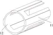
图3为本发明实施例的变刚度机构的下机构的示意图;3 is a schematic diagram of the lower mechanism of the variable stiffness mechanism of the embodiment of the present invention;
图4为本发明实施例的变刚度机构的结构示意图;Fig. 4 is the structural representation of the variable stiffness mechanism of the embodiment of the present invention;
图5为本发明实施例的内套与黏附材料层的装配图;5 is an assembly diagram of the inner sleeve and the adhesive material layer of the embodiment of the present invention;
图6为本发明实施例的连接结构的示意图;Fig. 6 is the schematic diagram of the connection structure of the embodiment of the present invention;
图中标号说明:1——头盔,2——变刚度机构,3——气管,4——衣服,5——阀门,6——上连接扣,7——复位弹簧,8——高刚度外套,9——下连接扣,10——气囊,11——黏附材料层,12——内套,13—滑块,14—复位簧。Notes in the figure: 1—helmet, 2—increasing stiffness mechanism, 3—trachea, 4—clothes, 5—valve, 6—upper connection buckle, 7—return spring, 8—high rigidity Overcoat, 9—lower connecting buckle, 10—air bag, 11—adhesive material layer, 12—inner sleeve, 13—slider, 14—return spring.
具体实施方式Detailed ways
下面对本发明技术方案进行详细说明,但是本发明的保护范围不局限于所述实施例。The technical solutions of the present invention will be described in detail below, but the protection scope of the present invention is not limited to the embodiments.
为了使本发明的目的、技术方案及优点更加清楚明白,以下结合附图1-5及实施例,对本发明进行进一步详细说明。应当理解,此处所描述的具体实施例仅用以解释本发明,并不用于限定本发明。In order to make the object, technical solution and advantages of the present invention clearer, the present invention will be further described in detail below in conjunction with accompanying drawings 1-5 and embodiments. It should be understood that the specific embodiments described here are only used to explain the present invention, not to limit the present invention.
如图1所示,本实施例系一种基于干黏附特性的变刚度惯性载荷消减装置,包括头盔1、七个变刚度机构2和一套气动单元,气动单元包括气管1、阀门5和外置气源。As shown in Figure 1, this embodiment is a variable stiffness inertial load reduction device based on dry adhesion characteristics, including a
头盔1的设计符合头部尺寸,被佩戴时与头紧密贴合。The design of the
七个变刚度机构2逐一均匀布置,七个变刚度机构2的上下两端均通过连接结构分别与头盔1与衣服4连接。The seven
如图2、3和4所示,所示,本实施例,变刚度机构2为气动执行机构,包括具有高刚度外套8的上机构和具有低刚度气驱膨胀内套12的下机构,具体为:As shown in Figures 2, 3 and 4, as shown in this embodiment, the
上机构包括上连接扣6、复位弹簧7和高刚度外套8,上连接扣6与高刚度外套8顶端外表面焊接在一起,复位弹簧7由高刚度外套8后端插入,且高刚度外套8顶端与复位弹簧7通过螺纹连接在一起,具体为,复位弹簧7端头固定一个连接块,连接块外表面设置外螺纹,高刚度外套顶端内表面设置内螺纹,两者螺纹连接。The upper mechanism includes an upper connecting
本实施例中,高刚度外套8采用轻质高强度金属材料制成,优先采用厚度为1.5mm的不锈钢制成。In this embodiment, the high-
下机构包括下连接扣9、气囊10、黏附材料层11和内套12,内套12套在气囊10的上部,内套12的顶端与气囊10之间胶粘,可在不破坏气囊密封性的情况下,使内套12与气囊10固定在一起;多条黏附材料层11粘贴在内套12的外表面上。气囊10下部分与下连接扣9通过铆钉连接在一起。The lower mechanism includes the
如图5所示,内套12为圆筒结构,内套12为具有低刚度气驱膨胀的内套,内套12采用低强度金属材料制成,本实施例优先采用铝合金制成。内套12上沿轴向间隔开设多条通槽,通槽延伸到内套12的底端,内套12的厚度小于等于0.5mm。在向气囊10充气后,气囊10膨胀将由通槽隔开的内套12部分向外顶起,使得粘贴在内套12外表面上的黏附材料层11与高刚度外套8的内缸壁黏附,气囊与高刚度外套的相对运动被约束。As shown in Fig. 5, the
如图3所示,变刚度机构的上机构的复位弹簧7与下机构的气囊10通过铆钉连接在一起,具体为,在气囊10端部一体成型一块外凸的连接部,复位弹簧7与此连接部之间通过铆钉连接。As shown in Figure 3, the
如图6所示,本实施例中,变刚度机构2与头盔1之间可拆卸式的连接结构,优先采用插接式连接结构,具体以变刚度机构2与头盔1连接为例,进一步说明:在头盔1上内嵌设置复位簧14和滑块13,滑块13周围为一凹槽,滑块13在复位簧14的作用下,在凹槽内有位移变化。As shown in Figure 6, in this embodiment, the detachable connection structure between the
在变刚度机构2与头盔1连接时,利用变刚度机构2内的上连接扣6与连接结构进行连接,具体为:在安装上连接扣6时,直接将上连接扣6推入头盔1上的凹槽,上连接扣6推动滑块13在凹槽移位,滑块13移位的同时压缩复位簧14;当上连接扣6安装到位后,复位簧14推动滑块13进入上连接扣6上的插槽内,滑块13将上连接扣6和头盔1锁定在一起。在拆卸上连接扣6时,手动将滑块13向后移位,从上连接扣6内的插槽脱离,上连接扣6和头盔1不再锁定在一起,可将上连接扣6从头盔1上拆卸下来。When the
本实施例中,变刚度机构2与衣服4的连接,实质为下连接扣9和衣服4的连接,本实施例中下连接扣9和衣服4优选采用按扣连接结构,具体为,在衣服4上和下连接扣9分别设置按扣的子母扣。In this embodiment, the connection between the
本实施例装置实现载荷消减的功能具体为:上机构套接下机构;下机构内气囊10在气压作用下膨胀,驱动下机构内的内套12产生形变,使固定在内套12外表面上的仿生黏附材料层11与上机构内高刚度外套的内壁面紧密接触,使变刚度机构2处于高刚度状态,传递惯性载荷,实现载荷消减的功能。The function of the device in this embodiment to achieve load reduction is specifically: the upper mechanism is connected to the lower mechanism; the
当下机构的内套在气压降低后直径减小,下机构和上机构脱离接触,变刚度机构2处于低刚度状态,上机构和下机构可以自由运动,没有约束。The diameter of the inner sleeve of the lower mechanism decreases after the air pressure decreases, the lower mechanism and the upper mechanism are out of contact, and the
本实施例采用的充气单元通过阀门5和气源来提供气压和流量,是由一个气源、阀门5、气管3组成的双向(正负向)气压回路系统,气管3是给变刚度机构输送气流的通道。气管3连通每个变刚度机构内的气囊10的气口。The inflatable unit used in this embodiment provides air pressure and flow through the
本实施例装置,还包括变刚度检测触发单元,变刚度检测触发单元包括两路独立的气压施加或排放的启动信号,分别为由使用人员主动施加的信号和由应用对象内置的加速度传感器给定的信号,使用人员主动施加信号为集成在应用对象控制系统内的主动启动信号。本实施例装置优选的应用对象为汽车、飞机或火车。The device in this embodiment also includes a variable stiffness detection trigger unit. The variable stiffness detection trigger unit includes two independent start signals for air pressure application or discharge, which are signals actively applied by the user and given by the built-in acceleration sensor of the application object. The signal, the signal actively applied by the user is the active start signal integrated in the application object control system. The preferred application objects of the device in this embodiment are automobiles, airplanes or trains.
举例说明, 本实施例装置的应用对象为汽车,在汽车的自身控制系统内接入一个主动启动信号,该主动启动信号由驾驶员进行控制,可以控制阀门打开或关闭,实现气压和流量的控制。这是使用人员主动施加信号,具体表现在,汽车内的人员感知到危险即将来临,主动启动该装置来保护头部。For example, the application object of the device in this embodiment is a car. An active start signal is connected to the car's own control system. The active start signal is controlled by the driver and can control the opening or closing of the valve to realize the control of air pressure and flow. . This is a signal that is actively applied by the user. Specifically, the person in the car senses that the danger is imminent and actively activates the device to protect the head.
在汽车的自身控制系统内的加速度传感器(若汽车没有,可以增设用于检测汽车速度增加的传感器)上接出一路启动信号,该路启动信号是在加速度传感器检测到汽车正常行驶过程中出现加速度异常情况时,启动该装置来保护头部。Connect a starting signal to the acceleration sensor in the car's own control system (if the car does not have one, you can add a sensor for detecting the speed increase of the car). In case of abnormal situation, activate the device to protect the head.
本实施例的基于干黏附特性的变刚度惯性载荷消减装置,变刚度机构根据不同惯性载荷可以选择不同的变刚度机构个数,可以选择1-7组,惯性载荷越大,变刚度机构越多。In the variable stiffness inertial load reduction device based on dry adhesion characteristics of this embodiment, the variable stiffness mechanism can choose different numbers of variable stiffness mechanisms according to different inertial loads, and can choose 1-7 groups. The greater the inertial load, the more variable stiffness mechanisms .
本实施例的基于干黏附特性的变刚度惯性载荷消减装置,未进行工作的情况下气囊10可在高刚度外套8中沿轴向自由移动,在进行工作的情况下气囊10充气膨胀将内套12撑开,推动附着的黏附材料层与高刚度外套8的内表面黏附,气囊10与高刚度外套8的相对运动被约束。内套12对气囊10相对高刚度外套8的运动起导向作用,黏附材料层可与光滑的高刚度外套黏附提高刚度。变刚度机构在未进行工作时,每个变刚度机构未锁定,工作人员的头颈部可以自由运动,在进行工作时,每个变刚度机构锁定,消减工作人员头颈部受到的惯性载荷。In the variable stiffness inertial load reduction device based on dry adhesion characteristics of this embodiment, the
本实施例的基于干黏附特性的变刚度惯性载荷消减装置,变刚度机构为气动执行机构,充气单元为变刚度机构供气及放气,变刚度检测触发单元为气动单元发送控制信号。变刚度机构的刚度变化是通过调节气囊气压来实现,同时在机构单元接触界面引入仿生黏附作用,以增大刚度变化极限,其中仿生黏附材料的应用使得本发明的变刚度技术远远优于传统气压变刚度技术的一个重要原因。In the variable stiffness inertial load reduction device based on dry adhesion characteristics in this embodiment, the variable stiffness mechanism is a pneumatic actuator, the inflatable unit supplies and deflates air to the variable stiffness mechanism, and the variable stiffness detection trigger unit sends control signals to the pneumatic unit. The stiffness change of the variable stiffness mechanism is realized by adjusting the air pressure of the airbag, and at the same time, the bionic adhesion is introduced at the contact interface of the mechanism unit to increase the stiffness change limit. The application of the bionic adhesion material makes the variable stiffness technology of the present invention far superior to the traditional one. An important reason for air pressure variable stiffness technology.
变刚度机构具有三个状态,分别为非工作状态、工作状态、工作响应结束状态:The variable stiffness mechanism has three states, which are non-working state, working state, and working response end state:
在非工作状态时,变刚度机构气囊处于负压状态,黏附材料层和高刚度外套脱开(间隙在1mm左右),处于刚度较小的状态,可沿轴向自由移动,头部处于自由状态,可以自由运动,在头部正视前方时,复位弹簧处于不受力状态,在头部扭转或低头时,头盔带动高刚度外套伸出,复位弹簧处于拉伸状态,需要克服复位弹簧的拉力(很小),当头部恢复正视前方时,气囊在复位弹簧拉力的作用下,恢复至初始位置。In the non-working state, the airbag of the variable stiffness mechanism is in a negative pressure state, the adhesive material layer and the high rigidity jacket are disengaged (the gap is about 1mm), and it is in a state of low stiffness, which can move freely in the axial direction, and the head is in a free state , can move freely. When the head looks straight ahead, the return spring is in a state of no force. When the head is twisted or lowered, the helmet drives the high-rigidity jacket to stretch out, and the return spring is in a stretched state. It needs to overcome the tension of the return spring ( Very small), when the head returns to look straight ahead, the airbag returns to its original position under the tension of the return spring.
在工作状态时,阀门5的进气口开启,供气系统迅速对气囊10进行充气,气囊10膨胀,将内套12向外侧抬起,内套12外表面粘贴的黏附材料与高刚度外套的缸体内表面贴合,形成较大界面作用力,刚度较大,高刚度外套和气囊基本不发生相对滑动。In the working state, the air inlet of the
在工作响应结束状态,阀门5的出气口开启,气囊10内气体排出,气囊内恢复负压状态,内套12恢复原状,使得黏附材料层与高刚度外套体内壁脱离,刚度恢复到较低水平,变刚度机构可沿轴向自由移动,头部可以自由活动。At the end of the work response, the air outlet of the
在变刚度机构的三个状态下,内套12对气囊10的相对高刚度外套8的运动起导向作用,黏附材料层11可与光滑的高刚度外套8黏附提高刚度。In the three states of the variable stiffness mechanism, the
基于干黏附特性的变刚度惯性载荷消减装置也具有三个状态:在非工作状态时,变刚度机构每个单元位置没有锁定,刚度小,头部处于自由状态,可以自由运动,在运动过程中仅仅需要克服每个变刚度机构的复位弹簧的施加的力而已;当使用人员将要受到惯性载荷时,使用人员操控控制系统发出工作信号,该防护装置进入工作状态,供气系统进入充气的工作状态,变刚度机构每个单元位置锁定,刚度增大,变刚度机构将头盔固定,消除使用人员的惯性载荷,防止在过载的情况下工作人员头部前倾。当工作人员所受的惯性载荷撤销后,防护装置进入工作响应结束状态,供气系统进入泄气的工作状态,变刚度机构恢复到原来刚度小的状态,头部又处于可以自由运动的状态。The variable stiffness inertial load reduction device based on dry adhesion characteristics also has three states: in the non-working state, the position of each unit of the variable stiffness mechanism is not locked, the stiffness is small, the head is in a free state, and can move freely. It only needs to overcome the force applied by the return spring of each variable stiffness mechanism; when the user is about to be subjected to inertial load, the user controls the control system to send a working signal, the protective device enters the working state, and the air supply system enters the working state of inflation , The position of each unit of the variable stiffness mechanism is locked, and the stiffness increases. The variable stiffness mechanism fixes the helmet, eliminates the inertial load of the user, and prevents the worker's head from tilting forward under overload conditions. When the inertial load suffered by the staff is removed, the protective device enters the end of the work response state, the air supply system enters the deflated working state, the variable stiffness mechanism returns to the original state of low stiffness, and the head is in a state of free movement again.
以上实施例仅为说明本发明的技术思想,不能以此限定本发明的保护范围,凡是按照本发明提出的技术思想,在技术方案基础上所做的任何改动,均落入本发明保护范围之内。The above embodiments are only to illustrate the technical ideas of the present invention, and cannot limit the scope of protection of the present invention with this. Any changes made on the basis of technical solutions according to the technical ideas proposed in the present invention all fall within the scope of protection of the present invention. Inside.
Claims (10)
Translated fromChinesePriority Applications (1)
| Application Number | Priority Date | Filing Date | Title |
|---|---|---|---|
| CN202310328125.6ACN116279269A (en) | 2023-03-30 | 2023-03-30 | Variable-rigidity inertial load reduction device based on dry adhesion characteristics |
Applications Claiming Priority (1)
| Application Number | Priority Date | Filing Date | Title |
|---|---|---|---|
| CN202310328125.6ACN116279269A (en) | 2023-03-30 | 2023-03-30 | Variable-rigidity inertial load reduction device based on dry adhesion characteristics |
Publications (1)
| Publication Number | Publication Date |
|---|---|
| CN116279269Atrue CN116279269A (en) | 2023-06-23 |
Family
ID=86803171
Family Applications (1)
| Application Number | Title | Priority Date | Filing Date |
|---|---|---|---|
| CN202310328125.6APendingCN116279269A (en) | 2023-03-30 | 2023-03-30 | Variable-rigidity inertial load reduction device based on dry adhesion characteristics |
Country Status (1)
| Country | Link |
|---|---|
| CN (1) | CN116279269A (en) |
Citations (8)
| Publication number | Priority date | Publication date | Assignee | Title |
|---|---|---|---|---|
| US6296280B1 (en)* | 1999-11-02 | 2001-10-02 | Trw Inc. | Adaptive collapsible steering column |
| WO2002002309A1 (en)* | 2000-06-30 | 2002-01-10 | Dwight Marcus | Controlled rigidity articles |
| US20030088906A1 (en)* | 2001-08-17 | 2003-05-15 | Baker Gregg S. | Head stabilizing system |
| US20150157080A1 (en)* | 2013-12-11 | 2015-06-11 | Board Of Trustees Of The Leland Stanford Junior University | Device to reduce head injury risk |
| CN111687820A (en)* | 2020-05-12 | 2020-09-22 | 天津大学 | Rigidity-variable exoskeleton structure based on positive pressure friction principle |
| CN112025749A (en)* | 2020-08-28 | 2020-12-04 | 燕山大学 | A Soft Gripper with Wide Range of Variable Stiffness |
| CN112681920A (en)* | 2021-01-27 | 2021-04-20 | 林君泽 | Self-adaptive damper |
| CN113348864A (en)* | 2021-07-14 | 2021-09-07 | 南京航空航天大学 | Small fruit and vegetable picking mechanism based on bionic adhesion |
- 2023
- 2023-03-30CNCN202310328125.6Apatent/CN116279269A/enactivePending
Patent Citations (8)
| Publication number | Priority date | Publication date | Assignee | Title |
|---|---|---|---|---|
| US6296280B1 (en)* | 1999-11-02 | 2001-10-02 | Trw Inc. | Adaptive collapsible steering column |
| WO2002002309A1 (en)* | 2000-06-30 | 2002-01-10 | Dwight Marcus | Controlled rigidity articles |
| US20030088906A1 (en)* | 2001-08-17 | 2003-05-15 | Baker Gregg S. | Head stabilizing system |
| US20150157080A1 (en)* | 2013-12-11 | 2015-06-11 | Board Of Trustees Of The Leland Stanford Junior University | Device to reduce head injury risk |
| CN111687820A (en)* | 2020-05-12 | 2020-09-22 | 天津大学 | Rigidity-variable exoskeleton structure based on positive pressure friction principle |
| CN112025749A (en)* | 2020-08-28 | 2020-12-04 | 燕山大学 | A Soft Gripper with Wide Range of Variable Stiffness |
| CN112681920A (en)* | 2021-01-27 | 2021-04-20 | 林君泽 | Self-adaptive damper |
| CN113348864A (en)* | 2021-07-14 | 2021-09-07 | 南京航空航天大学 | Small fruit and vegetable picking mechanism based on bionic adhesion |
Similar Documents
| Publication | Publication Date | Title |
|---|---|---|
| US5402535A (en) | Restraining inflatable neck guard | |
| US4977623A (en) | User wearable inflatable garment | |
| US6125478A (en) | Protection system for the rider of a non-enclosed vehicle | |
| US3623768A (en) | Vehicular safety seat | |
| CN103786677B (en) | A kind of inflatable seat belt system | |
| CN103442955B (en) | For the constant area exhausr port of external impact decay air bag | |
| JP2009154812A (en) | Crew protection device | |
| CN108275110B (en) | A kind of anti-breakdown formula front double gasbag and its control method | |
| CN116279269A (en) | Variable-rigidity inertial load reduction device based on dry adhesion characteristics | |
| CN102756704A (en) | Double-cavity safety air bag device | |
| CN103318120B (en) | The automobile intelligent safety air bag of Shape-based interpolation memory alloy spring and method thereof | |
| CN101628550B (en) | Stretchable passenger car seat backrest | |
| CN107472181B (en) | A recovery device for vehicle active airbag airbag | |
| CN104791528A (en) | Automobile safety air bag deflation hole automatic pressure control valve | |
| Li | Wearable and controllable protective system design for elderly falling | |
| CN220764171U (en) | A head and neck inertial load reduction protective device combining suction and adhesion | |
| CN108162910A (en) | Motor vehicle air bag formula lap belt device and its control method | |
| CN211185948U (en) | Head protection air bag device integrating oxygenation self-rescue function | |
| CN117341554A (en) | A head and neck inertia load reduction protective device combined with suction and adhesive and its use method | |
| CN208086027U (en) | Airborne crew imitation airbag neck protection device | |
| CN206012385U (en) | Can automatic inflating multifunctional arm cushion | |
| CN120056906A (en) | Intelligent control system and control method for automobile safety belt | |
| EP2113430B1 (en) | Controlled valve to be used in gas bags in particular | |
| CN221729826U (en) | A helmet capable of reducing jaw pressure marks | |
| CN219969621U (en) | Safety airbag and vehicle |
Legal Events
| Date | Code | Title | Description |
|---|---|---|---|
| PB01 | Publication | ||
| PB01 | Publication | ||
| SE01 | Entry into force of request for substantive examination | ||
| SE01 | Entry into force of request for substantive examination |