CN116269575A - Nail head and medical anastomat - Google Patents
Nail head and medical anastomatDownload PDFInfo
- Publication number
- CN116269575A CN116269575ACN202111574430.0ACN202111574430ACN116269575ACN 116269575 ACN116269575 ACN 116269575ACN 202111574430 ACN202111574430 ACN 202111574430ACN 116269575 ACN116269575 ACN 116269575A
- Authority
- CN
- China
- Prior art keywords
- stop
- arm
- stopper
- nail head
- section
- Prior art date
- Legal status (The legal status is an assumption and is not a legal conclusion. Google has not performed a legal analysis and makes no representation as to the accuracy of the status listed.)
- Pending
Links
Images


Classifications
- A—HUMAN NECESSITIES
- A61—MEDICAL OR VETERINARY SCIENCE; HYGIENE
- A61B—DIAGNOSIS; SURGERY; IDENTIFICATION
- A61B17/00—Surgical instruments, devices or methods
- A61B17/068—Surgical staplers, e.g. containing multiple staples or clamps
- A61B17/072—Surgical staplers, e.g. containing multiple staples or clamps for applying a row of staples in a single action, e.g. the staples being applied simultaneously
- A61B17/07207—Surgical staplers, e.g. containing multiple staples or clamps for applying a row of staples in a single action, e.g. the staples being applied simultaneously the staples being applied sequentially
- A—HUMAN NECESSITIES
- A61—MEDICAL OR VETERINARY SCIENCE; HYGIENE
- A61B—DIAGNOSIS; SURGERY; IDENTIFICATION
- A61B17/00—Surgical instruments, devices or methods
- A61B17/068—Surgical staplers, e.g. containing multiple staples or clamps
- A61B17/072—Surgical staplers, e.g. containing multiple staples or clamps for applying a row of staples in a single action, e.g. the staples being applied simultaneously
- A61B2017/07214—Stapler heads
- A61B2017/07257—Stapler heads characterised by its anvil
- A—HUMAN NECESSITIES
- A61—MEDICAL OR VETERINARY SCIENCE; HYGIENE
- A61B—DIAGNOSIS; SURGERY; IDENTIFICATION
- A61B17/00—Surgical instruments, devices or methods
- A61B17/068—Surgical staplers, e.g. containing multiple staples or clamps
- A61B17/072—Surgical staplers, e.g. containing multiple staples or clamps for applying a row of staples in a single action, e.g. the staples being applied simultaneously
- A61B2017/07214—Stapler heads
- A61B2017/07271—Stapler heads characterised by its cartridge
- A—HUMAN NECESSITIES
- A61—MEDICAL OR VETERINARY SCIENCE; HYGIENE
- A61B—DIAGNOSIS; SURGERY; IDENTIFICATION
- A61B17/00—Surgical instruments, devices or methods
- A61B17/068—Surgical staplers, e.g. containing multiple staples or clamps
- A61B17/072—Surgical staplers, e.g. containing multiple staples or clamps for applying a row of staples in a single action, e.g. the staples being applied simultaneously
- A61B2017/07214—Stapler heads
- A61B2017/07285—Stapler heads characterised by its cutter
Landscapes
- Health & Medical Sciences (AREA)
- Life Sciences & Earth Sciences (AREA)
- Surgery (AREA)
- Heart & Thoracic Surgery (AREA)
- Engineering & Computer Science (AREA)
- Biomedical Technology (AREA)
- Nuclear Medicine, Radiotherapy & Molecular Imaging (AREA)
- Medical Informatics (AREA)
- Molecular Biology (AREA)
- Animal Behavior & Ethology (AREA)
- General Health & Medical Sciences (AREA)
- Public Health (AREA)
- Veterinary Medicine (AREA)
- Surgical Instruments (AREA)
Abstract
Translated fromChinese
Description
Translated fromChinese技术领域technical field
本发明涉及医疗器械技术领域,具体涉及一种钉头部及医用吻合器。The invention relates to the technical field of medical instruments, in particular to a nail head and a medical stapler.
背景技术Background technique
现有技术中,医用吻合器一般包括器械平台、活动连接于器械平台的击发把手和安装于器械平台的钉头部。钉仓组件可以通过穿刺器穿过身体上的小切口以接近手术部位实施手术。钉头部包括相对设置的钉仓组件和钉砧。所述钉仓组件一般包括钉仓、钉仓架、以及从吻合器的远端侧到近端侧依次设置的击发块、切刀和推刀杆,所述推刀杆位于一壳体中。在吻合器击发时,通过推刀杆推动切刀向远端侧运动,切刀运动过程中将钉仓组件和钉砧闭合,将位于钉仓组件和钉砧之间的组织切断,并驱动击发块将吻合钉推出于钉仓外并订合在组织上。In the prior art, a medical stapler generally includes an instrument platform, a firing handle movably connected to the instrument platform, and a nail head mounted on the instrument platform. The staple cartridge assembly can be passed through a small incision in the body with a trocar to access the surgical site. The nail head includes a nail cartridge assembly and a nail anvil which are arranged oppositely. The staple cartridge assembly generally includes a staple cartridge, a staple cartridge rack, and a firing block, a cutting knife, and a push knife rod arranged sequentially from the distal end to the proximal end of the stapler, and the push knife rod is located in a housing. When the stapler is fired, the cutter is pushed to the distal side by the pusher rod. During the movement of the cutter, the staple cartridge assembly and the anvil are closed, the tissue between the staple cartridge assembly and the anvil is cut off, and the firing is driven. The block pushes the staples out of the cartridge and staples them to the tissue.
操作者在完成上述缝切动作后,需要将吻合器复位,继而更换钉仓组件,以便医用吻合器进行下一次的缝切手术。但是,在手术过程中可能会出现操作者在未更换已击发的钉仓的情况下进行又一次击发的情况,或者在未安装钉仓的情况下击发,这样可能造成不良的后果。After the operator completes the above-mentioned suturing operation, he needs to reset the stapler, and then replace the staple cartridge assembly, so that the medical stapler can perform the next suturing operation. However, during the operation, it may happen that the operator performs another firing without replacing the fired staple cartridge, or fires without installing the staple cartridge, which may cause adverse consequences.
在本发明中,远端侧和近端侧是相对于操作者来说的,距离操作者较近的一端为近端侧,距离操作者较远的一端,即更靠近手术位置的一端为远端侧。In the present invention, the distal side and the proximal side are relative to the operator, the end closer to the operator is the proximal side, and the end farther away from the operator, that is, the end closer to the surgical site is the far side. end side.
发明内容Contents of the invention
针对现有技术中的问题,本发明的目的在于提供一种钉头部及医用吻合器,简单、有效地防止吻合器在未更换已击发的钉仓时的二次击发。In view of the problems in the prior art, the purpose of the present invention is to provide a nail head and a medical stapler, which can simply and effectively prevent the stapler from re-firing when the fired staple cartridge is not replaced.
本发明实施例提供一种钉头部,用于医用吻合器,所述钉头部包括:An embodiment of the present invention provides a nail head for a medical stapler, the nail head comprising:
第一钳夹和连接件,所述第一钳夹通过所述连接件连接于所述医用吻合器的器械平台;A first clamp and a connecting piece, the first clamp is connected to the instrument platform of the medical stapler through the connecting piece;
切刀,位于所述第一钳夹的近端侧,且至少一侧壁设置有第一止挡部;A cutting knife is located on the proximal side of the first jaw, and at least one side wall is provided with a first stopper;
至少一个止挡臂,所述止挡臂的近端侧连接于所述连接件,所述止挡臂包括第二止挡部;at least one stop arm, the proximal side of the stop arm is connected to the connector, the stop arm includes a second stop portion;
其中,所述止挡臂未受到外力处于第一状态时,所述止挡臂至少部分位于靠近所述切刀的一侧壁,且所述第二止挡部至少部分位于所述第一止挡部向所述第一钳夹的远端侧运动的路径上,所述止挡臂被驱动而至少部分向外侧横向运动处于第二状态时,所述第二止挡部脱离所述第一止挡部向所述第一钳夹的远端侧运动的路径,且此时所述止挡臂相对于所述第一状态时远离所述切刀的一侧壁。Wherein, when the stop arm is not subjected to external force and is in the first state, the stop arm is at least partially located on a side wall close to the cutter, and the second stop portion is at least partially located on the first stop On the path of movement of the stopper to the distal end side of the first jaw, when the stopper arm is driven to at least partially move outward laterally and is in the second state, the second stopper is disengaged from the first jaw. The path of the stopper moving toward the distal end side of the first jaw, and at this time, the stopper arm is away from the side wall of the cutting knife relative to the first state.
在一些实施例中,所述止挡臂未受到外力时,所述第二止挡部与所述第一止挡部形成嵌设配合。In some embodiments, when the stop arm is not subjected to external force, the second stop part forms an embedded fit with the first stop part.
在一些实施例中,所述第一止挡部为设置于所述切刀的侧面的凸台,所述第二止挡部包括止挡槽,所述止挡臂未受到外力时,所述凸台至少部分进入所述止挡槽中,且止位于所述止挡槽的远端;In some embodiments, the first stopper is a boss provided on the side of the cutter, the second stopper includes a stopper groove, and when the stopper arm is not subjected to external force, the The boss at least partially enters the stop groove and stops at the far end of the stop groove;
或者,所述第二止挡部为凸台,所述第一止挡部为设置于所述切刀的侧面的止挡槽,所述止挡臂未受到外力时,所述凸台至少部分进入所述止挡槽中,且止位于所述止挡槽的近端。Alternatively, the second stopper is a boss, and the first stopper is a stopper groove provided on the side of the cutter. When the stopper arm is not subjected to external force, the boss is at least partly Enter into the stop groove, and stop at the proximal end of the stop groove.
在一些实施例中,所述止挡槽沿轴向延伸,且所述止挡槽的轴向长度大于所述凸台的轴向长度,所述凸台可在所述止挡槽中沿轴向运动。In some embodiments, the stop groove extends axially, and the axial length of the stop groove is greater than the axial length of the boss, and the boss can move along the axis in the stop groove. to the movement.
在一些实施例中,还包括击发块,所述击发块包括驱动部,所述击发块位于所述第一钳夹的近端侧时,所述驱动部驱动所述止挡臂至少部分向外侧横向运动,以使得所述第二止挡部脱离所述第一止挡部向所述第一钳夹的远端侧运动的路径。In some embodiments, a firing block is further included, the firing block includes a driving part, and when the firing block is located on the proximal side of the first jaw, the driving part drives the stop arm at least partially outward lateral movement such that the second stop is out of the path of movement of the first stop toward the distal side of the first jaw.
在一些实施例中,所述止挡臂至少部分具有弹性,所述止挡臂被所述驱动部驱动而至少部分向外侧横向运动时,所述止挡臂至少部分发生横向的弹性变形;所述驱动部与所述止挡臂分离后,所述止挡臂回复到初始状态。In some embodiments, the stopper arm is at least partially elastic, and when the stopper arm is driven by the driving part to at least partially move laterally outward, the stopper arm at least partially undergoes lateral elastic deformation; After the driving part is separated from the stop arm, the stop arm returns to the initial state.
在一些实施例中,所述击发块位于所述第一钳夹的近端侧时,所述驱动部至少部分进入所述切刀的侧壁与所述止挡臂的内侧壁之间。In some embodiments, when the firing block is located at the proximal side of the first jaw, the driving portion at least partially enters between the side wall of the cutter and the inner side wall of the stop arm.
在一些实施例中,所述驱动部与所述止挡臂相对的一侧设置有第一引导面,和/或,所述止挡臂的远端内侧设置有第二引导面。In some embodiments, a first guide surface is provided on a side of the drive part opposite to the stop arm, and/or a second guide surface is provided on the inner side of the distal end of the stop arm.
在一些实施例中,所述止挡臂包括配合段和沿轴向延伸的第一连接段,所述配合段设置有所述第二止挡部,所述第一连接段连接于所述配合段的近端侧和所述连接件之间。In some embodiments, the stop arm includes a fitting section and a first connecting section extending axially, the fitting section is provided with the second stopper, the first connecting section is connected to the fitting between the proximal side of the segment and the connector.
在一些实施例中,所述止挡臂未受到外力时,所述配合段于所述第二止挡部处与所述切刀的侧壁之间的横向距离小于所述第一连接段与所述切刀的侧壁之间的横向距离。In some embodiments, when the stop arm is not subjected to external force, the lateral distance between the second stop part and the side wall of the cutter is smaller than the distance between the first connection part and the side wall of the cutter. The lateral distance between the side walls of the cutter.
在一些实施例中,所述连接件包括连接件本体和沿轴向延伸的固定臂,所述固定臂的近端侧连接于所述连接件本体的远端侧,所述固定臂包括第二连接段,所述第二连接段与所述第一连接段相固定。In some embodiments, the connector includes a connector body and an axially extending fixed arm, the proximal side of the fixed arm is connected to the distal side of the connector body, and the fixed arm includes a second A connection section, the second connection section is fixed to the first connection section.
在一些实施例中,所述第二连接段的形状与所述第一连接段的形状相适应;In some embodiments, the shape of the second connection section is adapted to the shape of the first connection section;
所述第二连接段固定于所述第一连接段的一侧,或者,所述第二连接段与所述第一连接段通过注塑相固定。The second connection section is fixed on one side of the first connection section, or the second connection section and the first connection section are fixed by injection molding.
在一些实施例中,所述止挡臂还包括第一延伸段,所述第一延伸段位于所述配合段的上方,所述固定臂还包括与所述第一延伸段的形状相适应的第二延伸段;In some embodiments, the stopper arm further includes a first extension section, the first extension section is located above the matching section, and the fixing arm further includes a shape adapted to the first extension section. the second extension;
所述第二延伸段固定于所述第一延伸段的一侧,或者,所述第二延伸段与所述第一延伸段通过注塑相固定。The second extension section is fixed on one side of the first extension section, or the second extension section and the first extension section are fixed by injection molding.
在一些实施例中,所述止挡臂与所述固定臂采用不同材质。In some embodiments, the stop arm and the fixing arm are made of different materials.
在一些实施例中,所述止挡臂为金属臂,所述固定臂为塑料臂,所述止挡臂与所述固定臂通过注塑相固定,所述止挡臂的第一延伸段和第一连接段分别设置有至少一个通孔。In some embodiments, the stopper arm is a metal arm, the fixed arm is a plastic arm, the stopper arm and the fixed arm are fixed by injection molding, the first extension section of the stopper arm and the second A connection segment is respectively provided with at least one through hole.
在一些实施例中,所述第一钳夹包括钉仓架,所述钉仓架的底面开设有配合孔,所述固定臂的底面至少部分进入所述配合孔中;In some embodiments, the first jaw includes a staple cartridge rack, a bottom surface of the staple cartridge frame is provided with a fitting hole, and the bottom surface of the fixing arm at least partially enters the fitting hole;
所述固定臂的近端侧设置有第一止位部,所述第一止位部与所述配合孔的近端面相抵持;和/或,所述固定臂的远端侧设置有第二止位部,所述第二止位部与所述配合孔的远端面相抵持。The proximal side of the fixed arm is provided with a first stop portion, and the first stop portion is opposed to the proximal surface of the matching hole; and/or, the distal side of the fixed arm is provided with a second Two stoppers, the second stopper is against the distal end surface of the matching hole.
在一些实施例中,所述连接件本体的近端侧设置有近端连接部,所述近端连接部固定于所述器械平台的钉匣外壳的远端侧;In some embodiments, the proximal side of the connector body is provided with a proximal connection part, and the proximal connection part is fixed to the distal side of the nail magazine shell of the instrument platform;
所述连接件本体的内部限定沿轴向延伸的通道,所述通道用于穿过所述医用吻合器的闭合拉片和击发杆。The interior of the connector body defines an axially extending channel for passing the closure tab and the firing rod of the medical stapler.
在一些实施例中,还包括第二钳夹和辅助打开件,所述第二钳夹的近端侧和所述第一钳夹的近端侧通过一闭合销相连接,所述辅助打开件可沿轴向方向运动,所述辅助打开件包括抬升部和销配合部;In some embodiments, it also includes a second jaw and an auxiliary opening member, the proximal side of the second jaw is connected to the proximal side of the first jaw through a closing pin, and the auxiliary opening member movable in the axial direction, the auxiliary opening member includes a lifting portion and a pin fitting portion;
所述闭合销向远端侧方向运动时,所述闭合销驱动所述销配合部带动所述辅助打开件向远端侧方向运动,所述抬升部驱动所述第二钳夹向远离所述第一钳夹的方向运动。When the closing pin moves toward the distal side, the closing pin drives the pin matching part to drive the auxiliary opening part to move toward the distal side, and the lifting part drives the second jaw to move away from the Movement in the direction of the first jaw.
在一些实施例中,所述辅助打开件的近端侧设置有第一配合部,所述固定臂的近端侧设置有第二配合部,所述辅助打开件向远端侧方向运动时,所述第一配合部止位于所述第二配合部。In some embodiments, the proximal side of the auxiliary opening member is provided with a first matching portion, and the proximal side of the fixing arm is provided with a second matching portion, when the auxiliary opening member moves toward the distal side, The first matching portion stops at the second matching portion.
在一些实施例中,所述连接件本体的远端侧包括止挡面,所述辅助打开件的近端侧设置有第三止挡部;In some embodiments, the distal side of the connector body includes a stopper surface, and the proximal side of the auxiliary opening member is provided with a third stopper;
所述闭合销向近端侧方向运动时,所述闭合销通过所述销配合部带动所述辅助打开件向近端侧方向运动,且所述第三止挡部止位于所述止挡面。When the closing pin moves towards the proximal side, the closing pin drives the auxiliary opening member to move towards the proximal side through the pin matching portion, and the third stopper stops at the stopper surface .
在一些实施例中,所述销配合部包括配合槽和设置于所述配合槽的侧壁的凸起部,所述配合槽的远端封闭,所述闭合销至少部分进入所述配合槽中,且位于所述配合槽的远端和所述凸起部之间;In some embodiments, the pin fitting portion includes a fitting groove and a protrusion disposed on a side wall of the fitting groove, the distal end of the fitting groove is closed, and the closing pin at least partially enters the fitting groove , and located between the distal end of the matching groove and the raised portion;
所述闭合销向近端侧方向运动时,所述闭合销与所述凸起部配合而带动所述辅助打开件向近端侧方向运动。When the closing pin moves toward the proximal side, the closing pin cooperates with the protrusion to drive the auxiliary opening part to move toward the proximal side.
本发明实施例还提供一种医用吻合器,包括上述的钉头部。An embodiment of the present invention also provides a medical stapler, including the aforementioned nail head.
本发明所提供的钉头部及医用吻合器具有如下优点:The nail head and the medical stapler provided by the present invention have the following advantages:
本发明提供了一种用于医用吻合器的钉仓组件,在连接件的远端设置一个止挡臂,在吻合器准备击发时,对所述止挡臂施加外力使其至少部分向外侧横向运动而远离切刀的侧壁,不阻挡所述切刀向远端侧方向的运动,此时可以正常击发吻合器。在吻合器击发完成后,切刀返回到钉头部的近端侧,该止挡臂未受到外力而靠近所述切刀的侧壁,通过第二止挡部和第一止挡部的配合阻挡所述切刀向远端侧方向运动,此时无法击发吻合器,从而有效地防止了吻合器在未更换已击发的钉仓时的二次击发。The present invention provides a staple cartridge assembly for a medical stapler. A stopper arm is arranged at the far end of the connecting piece. When the stapler is ready to be fired, an external force is applied to the stopper arm to at least partly laterally outward Move away from the side wall of the cutting knife, without blocking the movement of the cutting knife to the distal side, at this time, the stapler can be fired normally. After the firing of the stapler is completed, the cutting knife returns to the proximal side of the nail head, and the stopper arm is close to the side wall of the cutting knife without external force, through the cooperation of the second stopper part and the first stopper part The cutter is prevented from moving in the direction of the distal end, and the stapler cannot be fired at this time, thereby effectively preventing the stapler from being fired again when the fired staple cartridge is not replaced.
附图说明Description of drawings
通过阅读参照以下附图对非限制性实施例所作的详细描述,本发明的其它特征、目的和优点将会变得更明显。Other characteristics, objects and advantages of the present invention will become more apparent by reading the detailed description of non-limiting embodiments with reference to the following drawings.
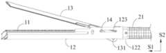
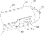
图1是本发明一实施例的钉头部和钉匣外壳配合的结构示意图;Fig. 1 is a schematic structural view of the cooperation of the nail head and the nail case shell in an embodiment of the present invention;
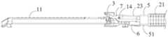
图2是本发明一实施例的去除钉仓架后的钉头部和钉匣外壳配合的结构示意图;Fig. 2 is a schematic structural view of the cooperation between the nail head and the nail magazine shell after removing the magazine rack according to an embodiment of the present invention;
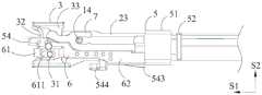
图3是本发明一实施例的去除钉仓和钉仓架后的钉头部与推刀杆配合的结构示意图;Fig. 3 is a structural schematic diagram of the cooperation between the nail head and the pusher rod after removing the staple cartridge and the staple cartridge frame according to an embodiment of the present invention;
图4是本发明一实施例的切刀的结构示意图;Fig. 4 is a schematic structural view of a cutter according to an embodiment of the present invention;
图5是本发明一实施例的切刀与连接组件配合的结构示意图;Fig. 5 is a structural schematic diagram of the cooperation between the cutter and the connecting assembly according to an embodiment of the present invention;
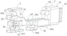
图6是本发明一实施例的连接组件与钉匣外壳配合的结构示意图;Fig. 6 is a structural schematic diagram of the cooperation between the connecting assembly and the nail magazine shell according to an embodiment of the present invention;
图7和图8是本发明一实施例的连接组件与钉仓架配合的结构示意图;Fig. 7 and Fig. 8 are structural schematic diagrams of the cooperation between the connecting assembly and the staple cartridge rack according to an embodiment of the present invention;
图9是本发明一实施例的止挡臂处于第一状态时,连接组件与切刀配合的仰视图;Fig. 9 is a bottom view of the coupling assembly and the cutter when the stopper arm is in the first state according to an embodiment of the present invention;
图10和图11是本发明一实施例的连接组件的结构示意图;10 and 11 are structural schematic diagrams of a connection assembly according to an embodiment of the present invention;
图12是本发明一实施例的连接件与止挡臂配合的示意图;Fig. 12 is a schematic diagram of the cooperation between the connector and the stop arm according to an embodiment of the present invention;
图13是本发明一实施例的击发块、切刀与连接组件配合的结构示意图;Fig. 13 is a structural schematic diagram of the cooperation of the firing block, the cutting knife and the connecting assembly according to an embodiment of the present invention;
图14是本发明一实施例的止挡臂处于第一状态时,击发块、切刀与连接组件配合的仰视图;Fig. 14 is a bottom view of the cooperation of the firing block, the cutting knife and the connecting assembly when the stopper arm is in the first state according to an embodiment of the present invention;
图15是本发明一实施例的击发块的结构示意图;Fig. 15 is a schematic structural diagram of a firing block according to an embodiment of the present invention;
图16和图17是本发明一实施例的辅助打开件与连接组件配合的结构示意图。Fig. 16 and Fig. 17 are structural schematic diagrams of cooperation between the auxiliary opening member and the connecting assembly according to an embodiment of the present invention.
附图标记:Reference signs:
11 钉仓 52 近端连接部11
12 钉仓架 53 止挡面12
121 配合孔 54 固定臂121
122 外套部 541 第二连接段122
113 第一销槽 542 第二延伸段113
13 钉砧 543 第一止位部(近)13
131 第二销槽 544 第二止位部(远)131
14 闭合销 545 第二配合部14
21 钉匣外壳 55 通道21
211 安装槽 6 止挡臂211
22 闭合拉片 61 配合段22
23 击发杆 611 止挡槽23
3 切刀 612 第二引导面3
31 凸台 62 第一连接段31
32 刀刃 63 第一延伸段32
33 切刀侧壁 64 通孔33
4 击发块 7 辅助打开件4
41 驱动部 71 抬升部41 Driving
411 第一引导面 72 配合槽411
42 推钉部 73 凸起部42
5 连接件 74 第一配合部5
51 连接件本体 75 第三止挡部51
具体实施方式Detailed ways
现在将参考附图更全面地描述示例实施方式。然而,示例实施方式能够以多种形式实施,且不应被理解为限于在此阐述的实施方式;相反,提供这些实施方式使得本发明将全面和完整,并将示例实施方式的构思全面地传达给本领域的技术人员。在图中相同的附图标记表示相同或类似的结构,因而将省略对它们的重复描述。Example embodiments will now be described more fully with reference to the accompanying drawings. Example embodiments may, however, be embodied in many forms and should not be construed as limited to the embodiments set forth herein; rather, these embodiments are provided so that this disclosure will be thorough and complete, and will fully convey the concept of example embodiments to those skilled in the art. The same reference numerals denote the same or similar structures in the drawings, and thus their repeated descriptions will be omitted.
本发明提供了一种用于医用吻合器的钉仓组件和包括该钉仓组件的医用吻合器。所述医用吻合器包括器械平台、活动连接于器械平台的击发把手和安装于器械平台的钉头部,所述钉头部位于所述器械平台的远端侧。所述钉头部包括:第一钳夹和连接件,所述第一钳夹通过所述连接件连接于所述医用吻合器的器械平台;切刀,至少一侧壁设置有第一止挡部;以及至少一个止挡臂,所述止挡臂的近端侧连接于所述连接件,所述止挡臂包括第二止挡部。所述止挡臂包括第一状态和第二状态,所述止挡臂处于第一状态时相比于第二状态更靠近所述切刀的一侧壁。The invention provides a staple cartridge assembly for a medical stapler and a medical stapler comprising the staple cartridge assembly. The medical stapler includes an instrument platform, a firing handle movably connected to the instrument platform, and a nail head installed on the instrument platform, and the nail head is located at the distal side of the instrument platform. The nail head includes: a first jaw and a connecting piece, the first jaw is connected to the instrument platform of the medical stapler through the connecting piece; a cutter, at least one side wall is provided with a first stop part; and at least one stop arm, the proximal side of the stop arm is connected to the connector, the stop arm includes a second stop part. The stop arm includes a first state and a second state, and when the stop arm is in the first state, it is closer to the side wall of the cutter than in the second state.
在吻合器准备击发时,对所述止挡臂施加外力使其至少部分向外侧横向运动而远离切刀的侧壁,所述第二止挡部脱离所述第一止挡部向所述第一钳夹的远端侧运动的路径,所述止挡臂处于第二状态,相比于第一状态时远离所述切刀的一侧壁。此时,所述止挡臂不阻挡所述切刀向远端侧方向的运动,通过驱动所述切刀向远端侧方向运动可以正常击发吻合器。在吻合器击发完成后,切刀返回到钉头部的近端侧,该止挡臂未受到外力而靠近所述切刀的侧壁,处于第一状态,所述第二止挡部位于所述第一止挡部向所述第一钳夹的远端侧运动的路径上,通过第二止挡部和第一止挡部的配合阻挡所述切刀向远端侧方向运动,此时无法击发吻合器,从而有效地防止了吻合器在未更换已击发的钉仓时的二次击发。When the stapler is ready to fire, an external force is applied to the stop arm so that at least part of it moves laterally outward and away from the side wall of the cutter, and the second stop part breaks away from the first stop part and moves toward the first stop arm. A path of movement of the distal side of the jaws, the stop arm being in the second state is farther from the side wall of the cutter than in the first state. At this time, the stopper arm does not block the movement of the cutting knife toward the distal side, and the stapler can be normally fired by driving the cutting knife to move toward the distal side. After the firing of the stapler is completed, the cutting knife returns to the proximal side of the nail head, the stopper arm is close to the side wall of the cutting knife without external force, and is in the first state, and the second stopper is located at the side wall of the cutting knife. On the path where the first stopper moves to the distal side of the first jaw, the movement of the cutting knife to the distal side is prevented by the cooperation of the second stopper and the first stopper. The stapler cannot be fired, thereby effectively preventing the stapler from firing again when the fired staple cartridge is not replaced.
下面结合附图详细介绍本发明各个具体实施例的钉头部的结构,可以理解的是,各个具体实施例不作为本发明的保护范围的限制。The structure of the nail head of each specific embodiment of the present invention will be described in detail below in conjunction with the accompanying drawings. It should be understood that each specific embodiment is not intended to limit the scope of protection of the present invention.
图1~17示出了本发明一实施例的钉头部的结构。如图1和图2所示,所述钉头部包括相对设置的第一钳夹和第二钳夹。以下以所述第一钳夹为钉仓组件,所述第二钳夹为钉砧13为例具体说明该实施例的结构。所述钉仓组件包括容纳吻合钉的钉仓11和容纳所述钉仓11的钉仓架12。所述钉头部还包括连接件5、切刀3和至少一个止挡臂6,所述连接件5和所述止挡臂6共同组成了连接组件。所述止挡臂6包括靠近所述切刀3的第一状态和远离所述切刀3的第二状态。所述钉仓组件和所述钉砧13通过所述连接件5连接于所述器械平台的钉匣外壳21。如图3~6所示,初始状态下,所述切刀3位于所述钉仓11的近端侧。所述切刀3的远端侧设置有用于切割组织的刀刃32,所述切刀3的至少一侧壁33设置有第一止挡部。所述止挡臂6的近端侧连接于所述连接件5,所述止挡臂6包括第二止挡部。1 to 17 show the structure of a nail head according to an embodiment of the present invention. As shown in FIG. 1 and FIG. 2 , the nail head includes a first jaw and a second jaw that are oppositely arranged. Hereinafter, the structure of this embodiment will be described in detail by taking the first jaw as a nail cartridge assembly and the second jaw as an
在吻合器准备击发时,对所述止挡臂6施加外力使其至少部分向外侧横向运动而远离切刀3的侧壁33,所述第二止挡部脱离所述第一止挡部向所述钉仓的远端侧运动的路径,此时,所述止挡臂6处于第二状态而不阻挡所述切刀3向远端侧方向的运动,通过驱动所述切刀3向远端侧方向运动可以正常击发吻合器。在吻合器击发完成后,切刀3返回到钉头部的近端侧,该止挡臂6未受到外力而靠近所述切刀3的侧壁33,处于第一状态,所述第二止挡部位于所述第一止挡部向所述钉仓的远端侧运动的路径上,通过第二止挡部和第一止挡部的配合阻挡所述切刀3向远端侧方向运动,此时无法击发吻合器,从而有效地防止了吻合器在未更换已击发的钉仓11时的二次击发。When the stapler is ready to fire, an external force is applied to the
在本发明中,远端侧和近端侧是相对于操作者来说的,距离操作者较近的一端为近端侧,距离操作者较远的一端,即更靠近手术位置的一端为远端侧,沿所述吻合器的轴心的方向为轴向,即从吻合器的远端侧到近端侧的方向,或从吻合器的近端侧到远端侧的方向。例如,在图1的视角中,对于钉仓架12来说,其远端侧为左边一侧,近端侧为右边一侧。定义图1中的S1方向为从吻合器的远端侧向近端侧的方向。将S1方向或与S1方向相反的方向为吻合器的轴向。定义图1中的S2方向为纵向方向,即高度方向。定义图14中的S3方向为横向方向,即宽度方向。在本发明中,对于一个部件来说,内侧和外侧是相对于吻合器的轴心来说的,靠近轴心的一侧为内侧,远离轴心的一侧为外侧。In the present invention, the distal side and the proximal side are relative to the operator, the end closer to the operator is the proximal side, and the end farther away from the operator, that is, the end closer to the surgical site is the far side. End side, the direction along the axis of the stapler is the axial direction, that is, the direction from the distal side to the proximal side of the stapler, or the direction from the proximal side to the distal side of the stapler. For example, in the viewing angle of FIG. 1 , for the
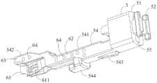
如图4和图5所示,在该实施例中,所述第一止挡部为设置于所述切刀3的侧面的凸台31。所述凸台31可以是圆柱形凸台、长方体凸台或者截面为梯形、菱形、椭圆形等其他形状的凸台。所述连接件5包括连接件本体51。所述止挡臂6包括配合段61和轴向延伸的第一连接段62,所述配合段61的近端侧通过所述第一连接段62连接于所述连接件本体51的远端侧。所述第二止挡部包括止挡槽611,所述止挡臂6未受到外力时,所述凸台31至少部分进入所述止挡槽611中,且止位于所述止挡槽611的远端。在该实施例中,所述止挡槽611是一个腰形槽,所述止挡槽611沿轴向延伸,且所述止挡槽611的轴向长度大于所述凸台31的轴向长度,所述凸台31可在所述止挡槽611中沿轴向运动。在另一实施方式中,所述止挡槽611也可以连通至所述配合段61的下表面或者上表面,只要满足所述止挡槽611的远端封闭而可以将所述凸台31止位于所述止挡槽611的远端侧即可。所述止挡槽611可以连通所述配合段61的内侧表面和外侧表面,也可以只在所述配合段61的内侧表面设置所述止挡槽61。在再一实施方式中,也可以所述第二止挡部为凸台,所述第一止挡部为设置于所述切刀3的侧面的止挡槽,所述止挡槽至少近端是封闭的,所述止挡臂未受到外力时,所述凸台至少部分进入所述止挡槽中,且止位于所述止挡槽的近端。在又一实施方式中,也可以所述第一止挡部和所述第二止挡部均为凸台,所述止挡臂6未受到外力时,所述第二止挡部位于所述第一止挡部的远端侧,阻挡所述第一止挡部向远端侧方向的运动。As shown in FIGS. 4 and 5 , in this embodiment, the first stop portion is a
如图6~8示出了所述连接件5与所述钉仓组件和所述钉匣外壳21的连接方式。如图6所示,所述连接件本体51的近端侧设置有近端连接部52,所述近端连接部52固定于所述器械平台的钉匣外壳21的远端侧。具体地,所述近端连接部52包括两个固定柱,所述钉匣外壳21中设置有与所述固定柱的形状相适应的安装槽211,所述固定柱固定于所述安装槽211中。所述钉匣外壳21包括上壳体和下壳体,图6中仅示例性地示出了下壳体的安装槽211,上壳体也设置有与所述下壳体的安装槽211相对应的安装槽。6 to 8 show the way of connecting the connecting
如图6所示,所述连接件本体51的内部限定沿轴向延伸的通道,所述通道用于穿过所述医用吻合器的闭合拉片22和击发杆23,所述击发杆23穿过所述通道后与所述切刀3的近端侧相配合,所述闭合拉片22穿过所述通道后与一个闭合销14相配合。所述连接件5还包括固定臂54,所述固定臂54的近端侧连接于所述连接件本体51的远端侧。所述钉仓架12的底面开设有配合孔121,所述固定臂54的底面至少部分进入所述配合孔121中。所述固定臂54的近端侧设置有第一止位部543,所述第一止位部543与所述配合孔121的近端面相抵持,所述固定臂54的远端侧设置有第二止位部544,所述第二止位部544与所述配合孔121的远端面相抵持。如图7所示,所述钉仓架12的近端侧设置有外套部122,所述外套部122套设于所述连接件本体51的外部,且所述连接件本体51的外轮廓与所述外套部122的内轮廓为非圆形截面,以防止所述外套部122相对于所述连接件本体51的旋转,且所述外套部122与所述连接件本体51互为紧密配合。As shown in FIG. 6 , the inside of the
下面结合图5、图9~15具体介绍该实施例的钉头部的工作过程。其中,图5和图9示出了在止挡臂6未受到外力时阻挡所述凸台31向远端侧方向运动的状态,以下称为第一状态,图13和图14示出了止挡臂6受到外力向外侧横向运动,而使得止挡槽611不阻挡凸台31向远端侧方向运动时的状态,以下称为第二状态。Below in conjunction with Fig. 5, Fig. 9~15 specifically introduces the working process of the nail head of this embodiment. Among them, Fig. 5 and Fig. 9 have shown the state that stops described
所述钉仓组件还包括击发块4,所述击发块4包括推钉部42。在吻合器击发时,所述切刀3可以驱动所述击发块4向远端侧方向运动,而使得所述推钉部42将所述钉仓11中的吻合钉向所述钉砧13推出。在该实施例中,所述止挡臂6在第一状态和第二状态之间的切换通过所述击发块4来实现。如图15所示,所述击发块4还包括驱动部41,所述驱动部41为所述击发块4的近端侧设置的延伸臂。所述击发块4位于所述钉仓11的近端侧时,所述驱动部41驱动所述止挡臂6向外侧横向运动,以使得所述止挡臂6从第一状态进入第二状态,所述止挡槽611与所述凸台31分离。The staple cartridge assembly further includes a
在该实施例中,所述止挡臂6至少部分具有弹性,例如所述止挡臂6可以采用一个金属薄片制成,但本发明不限于此。所述止挡臂6被所述驱动部41驱动向外侧横向运动时,所述止挡臂6至少部分发生横向的弹性变形;所述驱动部41与所述止挡臂6分离后,所述配合段61在弹性变形恢复力的作用下回复到初始状态。In this embodiment, at least part of the
初始状态下,所述切刀3和所述击发块4均位于所述钉仓组件的近端侧。所述击发块4的驱动部41驱动所述止挡臂6向外侧横向运动,使得所述止挡臂6进入所述第二状态,所述止挡臂6至少部分发生横向的弹性变形,所述止挡槽611与所述凸台31分离。此时,通过击发杆23驱动所述切刀3向远端侧方向运动,所述切刀3驱动所述击发块4向远端侧方向运动而向钉砧13推出吻合钉,吻合钉订合在组织上,同时所述切刀3切割组织,也就完成了吻合器的击发。在吻合器击发完成后,所述切刀3重新返回到所述钉仓组件的近端侧,而所述击发块4留在所述钉仓组件的远端侧。此时,所述止挡臂6不再受到所述击发块4的作用力,所述止挡臂6在弹性变形恢复力的作用下重新返回到第一状态,即所述止挡槽611与所述凸台31形成嵌设配合,并且所述凸台31止位于所述止挡槽611的远端,即无法驱动切刀3向远端侧方向运动而击发吻合器。In an initial state, both the
如图5和图9所示,在所述止挡臂6处于所述第一状态时,所述凸台31至少部分进入到所述止挡槽611中,且止位于所述止挡槽611的远端。通过所述击发杆23给所述切刀3一个向远端侧方向运动的力时,由于所述凸台31被所述止挡槽611的远端面所阻挡,所述切刀3无法继续向远端侧方向运动,也就无法击发吻合器。如图9所示,所述止挡臂6未受到外力时,所述配合段61于所述止挡槽611处与所述切刀3的侧壁33之间的横向距离(沿S3方向的距离)小于所述第一连接段62与所述切刀3的侧壁33之间的横向距离(沿S3方向的距离),即所述止挡槽611相比于所述第一连接段62更靠近所述切刀3的侧壁。由此,在所述击发块4进入到所述配合段61和所述切刀3的侧壁33之间时,在所述配合段61和所述第一连接段62的连接位置处更容易发生弹性变形,使得所述配合段61朝外侧横向运动。在该实施例中,所述切刀3的两侧均设置有所述凸台31,且所述切刀3的两侧分别设置有一个止挡臂6,各个止挡臂6的止挡槽611分别与一个凸台31形成嵌设配合。两个所述止挡臂6于所述止挡槽611处的横向间距小于两个所述止挡臂6的第一连接段62之间的横向间距,所述止挡臂6于所述止挡槽611处朝向所述切刀3的侧壁33倾斜。As shown in FIG. 5 and FIG. 9 , when the
如图10~12所示,在该实施例中,所述止挡臂6通过所述固定臂54固定于所述连接件本体51的远端侧。所述固定臂54包括第二连接段541,所述第二连接段541与所述第一连接段62相固定,通过所述第二连接段541与所述第一连接段62的连接配合,可以加强所述止挡臂6的第一连接段62的结构强度,并且将所述止挡臂6固定于所述连接件本体51的远端侧。在该实施例中,所述第二连接段541的形状与所述第一连接段62的形状相适应。所述第二连接段541固定于所述第一连接段62的一侧,例如通过贴合、焊接等方式,或者,所述第二连接段541与所述第一连接段62通过注塑相固定。为了进一步提高所述止挡臂6与所述固定臂54的配合,所述止挡臂6还包括第一延伸段63,所述第一延伸段63位于所述配合段61的上方,且与所述配合段61分离设置,即不会阻碍所述配合段61的横向运动,所述固定臂54还包括与所述第一延伸段63的形状相适应的第二延伸段542。所述第二延伸段542固定于所述第一延伸段63的一侧,例如通过贴合、焊接等方式,或者,所述第二延伸段542与所述第一延伸段63通过注塑相固定。As shown in FIGS. 10-12 , in this embodiment, the
所述止挡臂6和所述固定臂54可选采用不同的材质制成,两者结合后可以获得更好的配合。在该实施例中,所述止挡臂6为金属臂,所述固定臂54为塑料臂,所述止挡臂6与所述固定臂54通过注塑相固定,所述止挡臂6的第一延伸段63和第一连接段62分别设置有至少一个通孔64,以加强在注塑过程中所述止挡臂6和所述固定臂54之间的结合强度。The
如图13~15所示,在所述击发块4处于所述钉仓组件的近端侧时,所述驱动部41至少部分进入所述切刀3的侧壁33与所述配合段61的内侧壁之间,将所述配合段61向外侧撑开,使得所述配合段61向外侧横向运动,所述止挡槽611脱离所述凸台31。在该实施例中,所述击发块4对应设置有两个所述驱动部41。此时,通过击发杆23驱动所述切刀3向远端侧方向运动时,所述切刀3可以驱动击发块4一起向远端侧方向运动,所述击发块4将吻合钉推出,所述切刀3切割组织,进行吻合器的击发。为了更好地引导所述驱动部41进入到所述配合段61和所述切刀3的侧壁33之间,所述驱动部41与所述止挡臂6相对的一侧设置有倾斜的第一引导面411,所述配合段61的远端内侧设置有倾斜的第二引导面612。As shown in FIGS. 13-15 , when the
如图1所示,所述钉头部包括相对设置的钉砧13和钉仓组件,所述钉砧13具有相对于所述钉仓组件打开的第三状态和相对于所述钉仓组件闭合的第四状态。所述钉砧13的近端侧设置有倾斜设置的第一销槽123,所述钉仓组件的近端侧设置有沿轴向延伸的第二销槽131,一个闭合销14同时穿设于所述第一销槽123和所述第二销槽131中。所述闭合销14位于所述第二销槽131的远端侧时,所述钉砧13处于所述第三状态,所述闭合销14从所述第二销槽131的远端侧向近端侧运动时,所述钉砧13进入所述第四状态,所述钉砧13和所述钉仓组件夹紧组织。所述钉砧13从所述第三状态进入所述第四状态的过程,称为所述钉头部的闭合过程。所述器械平台中设置有用于闭合所述钉头部的闭合拉片22,所述闭合拉片22的远端侧连接于所述闭合销14,所述闭合拉片22向近端侧运动时,即可以拉动所述闭合销14向近端侧运动,而实现钉头部的闭合。As shown in FIG. 1, the nail head includes an
如图16和图17所示,在该实施例中,所述钉头部还包括辅助打开件7,用于在吻合器击发完成后辅助打开所述钉头部,所述辅助打开件7可沿轴向方向运动。所述辅助打开件7包括抬升部71和销配合部。如图16所示,所述抬升部71为朝向所述第二夹钳方向设置的凸起部。图16示出了在钉头部打开时所述辅助打开件7和所述闭合销14的位置,图17示出了在钉头部闭合时所述辅助打开件7和所述闭合销14的位置。在该实施例中,所述销配合部包括配合槽72和设置于所述配合槽72的侧壁的凸起部73,所述配合槽72的远端封闭,所述闭合销14至少部分进入所述配合槽72中,且位于所述配合槽72的远端和所述凸起部73之间。所述凸起部73位置处所述配合槽72的开口高度小于所述闭合销14的直径,将所述闭合销14保持在所述配合槽72内,不会与所述配合槽72分离。As shown in Figures 16 and 17, in this embodiment, the nail head further includes an
在驱动所述闭合拉片22向近端侧方向运动时,所述闭合拉片22带动所述闭合销14向近端侧方向运动,所述闭合销14与所述凸起部73配合而带动所述辅助打开件7向近端侧方向运动。所述连接件本体51的远端侧包括止挡面53,所述辅助打开件7的近端侧设置有第三止挡部75。所述辅助打开件7向近端侧方向运动时,所述第三止挡部75止位于所述止挡面53,从而对所述辅助打开件7向近端侧方向的运动范围进行限定。此时,所述闭合销14和所述辅助打开件7位于图17所处的位置,所述钉头部闭合,且所述辅助打开件7的抬升部71不会对所述钉砧13起到抬升的作用,保持钉头部闭合的稳定性。When the
在图17的状态下,吻合器击发完成后,需要将钉头部打开时,通过所述闭合拉片22驱动所述闭合销14向远端侧方向运动,所述闭合销14与所述配合槽72的远端面抵持而驱动所述辅助打开件7向远端侧方向运动。此时,所述抬升部71驱动所述钉砧13向远离所述钉仓架12的方向运动,以辅助打开所述钉头部。所述钉头部打开完成后,所述闭合销14和所述辅助打开件7又返回到图16示出的状态。所述辅助打开件7的近端侧设置有第一配合部74,所述固定臂54的近端侧设置有第二配合部545,所述辅助打开件7向远端侧方向运动时,所述第一配合部74止位于所述第二配合部545,从而对所述辅助打开件7向远端侧方向的运动范围进行限定。在该实施例中,所述辅助打开件7位于所述固定臂54的上方。所述第一配合部74为设置于所述辅助打开件7的近端侧朝向下方的凸起,所述第二配合部545为设置于所述固定臂54的近端向下的凹部,或者,也可以所述第一配合部74为凹部,所述第二配合部545为凸起。In the state of FIG. 17, after the firing of the stapler is completed, when the head of the nail needs to be opened, the
上面的实施例中以所述第一钳夹为钉仓组件,所述第二钳夹为钉砧为例进行说明。可以理解的是,在其他可替代的实施方式中,也可以所述第一钳夹为钉砧,所述第二钳夹为钉仓组件,也属于本发明的保护范围之内。In the above embodiments, the first jaw is a nail cartridge assembly and the second jaw is an anvil as an example. It can be understood that, in other alternative implementation manners, the first jaw may also be an anvil, and the second jaw may be a nail cartridge assembly, which also falls within the protection scope of the present invention.
以上内容是结合具体的优选实施方式对本发明所作的进一步详细说明,不能认定本发明的具体实施只局限于这些说明。对于本发明所属技术领域的普通技术人员来说,在不脱离本发明构思的前提下,还可以做出若干简单推演或替换,都应当视为属于本发明的保护范围。The above content is a further detailed description of the present invention in conjunction with specific preferred embodiments, and it cannot be assumed that the specific implementation of the present invention is limited to these descriptions. For those of ordinary skill in the technical field of the present invention, without departing from the concept of the present invention, some simple deduction or replacement can be made, which should be regarded as belonging to the protection scope of the present invention.
Claims (22)
Translated fromChinesePriority Applications (1)
| Application Number | Priority Date | Filing Date | Title |
|---|---|---|---|
| CN202111574430.0ACN116269575A (en) | 2021-12-21 | 2021-12-21 | Nail head and medical anastomat |
Applications Claiming Priority (1)
| Application Number | Priority Date | Filing Date | Title |
|---|---|---|---|
| CN202111574430.0ACN116269575A (en) | 2021-12-21 | 2021-12-21 | Nail head and medical anastomat |
Publications (1)
| Publication Number | Publication Date |
|---|---|
| CN116269575Atrue CN116269575A (en) | 2023-06-23 |
Family
ID=86820904
Family Applications (1)
| Application Number | Title | Priority Date | Filing Date |
|---|---|---|---|
| CN202111574430.0APendingCN116269575A (en) | 2021-12-21 | 2021-12-21 | Nail head and medical anastomat |
Country Status (1)
| Country | Link |
|---|---|
| CN (1) | CN116269575A (en) |
Citations (7)
| Publication number | Priority date | Publication date | Assignee | Title |
|---|---|---|---|---|
| US20140263569A1 (en)* | 2013-03-13 | 2014-09-18 | Covidien Lp | Surgical stapling apparatus |
| US20190167266A1 (en)* | 2017-11-29 | 2019-06-06 | Intuitive Surgical Operations, Inc. | Surgical Instrument With Lockout Mechanism |
| CN110099635A (en)* | 2016-12-21 | 2019-08-06 | 爱惜康有限责任公司 | With can the closure of independent actuation and the surgical stapling device of trigger system |
| JP2020501819A (en)* | 2016-12-21 | 2020-01-23 | エシコン エルエルシーEthicon LLC | Protective cover mechanism for joint interface between movable jaw and actuator shaft of surgical instrument |
| US20200261081A1 (en)* | 2019-02-19 | 2020-08-20 | Ethicon Llc | Surgical stapling assembly with cartridge based retainer configured to unlock a firing lockout |
| CN112165909A (en)* | 2018-03-28 | 2021-01-01 | 爱惜康有限责任公司 | Surgical stapler having an arrangement for retaining its firing member in a locked configuration unless a compatible cartridge has been installed therein |
| CN217118494U (en)* | 2021-12-21 | 2022-08-05 | 天臣国际医疗科技股份有限公司 | Nail head and medical anastomat |
- 2021
- 2021-12-21CNCN202111574430.0Apatent/CN116269575A/enactivePending
Patent Citations (7)
| Publication number | Priority date | Publication date | Assignee | Title |
|---|---|---|---|---|
| US20140263569A1 (en)* | 2013-03-13 | 2014-09-18 | Covidien Lp | Surgical stapling apparatus |
| CN110099635A (en)* | 2016-12-21 | 2019-08-06 | 爱惜康有限责任公司 | With can the closure of independent actuation and the surgical stapling device of trigger system |
| JP2020501819A (en)* | 2016-12-21 | 2020-01-23 | エシコン エルエルシーEthicon LLC | Protective cover mechanism for joint interface between movable jaw and actuator shaft of surgical instrument |
| US20190167266A1 (en)* | 2017-11-29 | 2019-06-06 | Intuitive Surgical Operations, Inc. | Surgical Instrument With Lockout Mechanism |
| CN112165909A (en)* | 2018-03-28 | 2021-01-01 | 爱惜康有限责任公司 | Surgical stapler having an arrangement for retaining its firing member in a locked configuration unless a compatible cartridge has been installed therein |
| US20200261081A1 (en)* | 2019-02-19 | 2020-08-20 | Ethicon Llc | Surgical stapling assembly with cartridge based retainer configured to unlock a firing lockout |
| CN217118494U (en)* | 2021-12-21 | 2022-08-05 | 天臣国际医疗科技股份有限公司 | Nail head and medical anastomat |
Similar Documents
| Publication | Publication Date | Title |
|---|---|---|
| CN204364049U (en) | A kind of nail-head component and chamber mirror surgical operation seaming and cutting device | |
| CN217118487U (en) | Drive mechanism and medical stapler | |
| US20210161527A1 (en) | Staple cartridge assembly and medical stapler using the staple cartridge assembly | |
| CN118105118B (en) | Surgical instrument, guide assembly thereof and detaching tool | |
| CN219207107U (en) | Nail head and surgical stapler | |
| CN105796145B (en) | A kind of nail-head component and hysteroscope surgical operation seaming and cutting device | |
| CN217118494U (en) | Nail head and medical anastomat | |
| CN217118488U (en) | Closing switching mechanism and medical anastomat | |
| CN218684551U (en) | Closed driving mechanism and medical stapler | |
| CN217118489U (en) | Closing switching mechanism and medical anastomat | |
| CN116269575A (en) | Nail head and medical anastomat | |
| CN216257262U (en) | Nail bin assembly and medical anastomat | |
| CN112438765B (en) | Closed driving mechanism and medical stapler including the same | |
| CN108125697B (en) | Surgical instrument | |
| CN217118495U (en) | Nail head and medical anastomat | |
| CN217853125U (en) | Nail head and medical anastomat | |
| CN216060621U (en) | Nail head and medical anastomat | |
| CN216221543U (en) | Anastomat assembly and anastomat | |
| CN116262055B (en) | Closed drive mechanism and medical stapler | |
| CN201939413U (en) | Linear type sewing-cutting machine | |
| CN116262054B (en) | Closed switching mechanism and medical stapler | |
| CN215874788U (en) | staple cartridge assembly and medical stapler | |
| CN116269574A (en) | Nail heads and medical staplers | |
| CN112807041B (en) | Nail cartridge assembly and medical stapler | |
| CN216167631U (en) | Nail bin assembly and medical anastomat |
Legal Events
| Date | Code | Title | Description |
|---|---|---|---|
| PB01 | Publication | ||
| PB01 | Publication | ||
| SE01 | Entry into force of request for substantive examination | ||
| SE01 | Entry into force of request for substantive examination |