CN116268601A - Ultrasonic atomizing sheet, atomizer and aerosol generating device - Google Patents
Ultrasonic atomizing sheet, atomizer and aerosol generating deviceDownload PDFInfo
- Publication number
- CN116268601A CN116268601ACN202111569102.1ACN202111569102ACN116268601ACN 116268601 ACN116268601 ACN 116268601ACN 202111569102 ACN202111569102 ACN 202111569102ACN 116268601 ACN116268601 ACN 116268601A
- Authority
- CN
- China
- Prior art keywords
- sheet
- piezoelectric ceramic
- electrode layer
- hole
- tab
- Prior art date
- Legal status (The legal status is an assumption and is not a legal conclusion. Google has not performed a legal analysis and makes no representation as to the accuracy of the status listed.)
- Pending
Links
Images


Classifications
- A—HUMAN NECESSITIES
- A24—TOBACCO; CIGARS; CIGARETTES; SIMULATED SMOKING DEVICES; SMOKERS' REQUISITES
- A24F—SMOKERS' REQUISITES; MATCH BOXES; SIMULATED SMOKING DEVICES
- A24F40/00—Electrically operated smoking devices; Component parts thereof; Manufacture thereof; Maintenance or testing thereof; Charging means specially adapted therefor
- A24F40/40—Constructional details, e.g. connection of cartridges and battery parts
- A24F40/46—Shape or structure of electric heating means
- A—HUMAN NECESSITIES
- A24—TOBACCO; CIGARS; CIGARETTES; SIMULATED SMOKING DEVICES; SMOKERS' REQUISITES
- A24F—SMOKERS' REQUISITES; MATCH BOXES; SIMULATED SMOKING DEVICES
- A24F40/00—Electrically operated smoking devices; Component parts thereof; Manufacture thereof; Maintenance or testing thereof; Charging means specially adapted therefor
- A24F40/40—Constructional details, e.g. connection of cartridges and battery parts
- Y—GENERAL TAGGING OF NEW TECHNOLOGICAL DEVELOPMENTS; GENERAL TAGGING OF CROSS-SECTIONAL TECHNOLOGIES SPANNING OVER SEVERAL SECTIONS OF THE IPC; TECHNICAL SUBJECTS COVERED BY FORMER USPC CROSS-REFERENCE ART COLLECTIONS [XRACs] AND DIGESTS
- Y02—TECHNOLOGIES OR APPLICATIONS FOR MITIGATION OR ADAPTATION AGAINST CLIMATE CHANGE
- Y02B—CLIMATE CHANGE MITIGATION TECHNOLOGIES RELATED TO BUILDINGS, e.g. HOUSING, HOUSE APPLIANCES OR RELATED END-USER APPLICATIONS
- Y02B30/00—Energy efficient heating, ventilation or air conditioning [HVAC]
- Y02B30/70—Efficient control or regulation technologies, e.g. for control of refrigerant flow, motor or heating
Landscapes
- Apparatuses For Generation Of Mechanical Vibrations (AREA)
Abstract
Description
Translated fromChinese技术领域technical field
本发明属于模拟吸烟技术领域,特别地,涉及一种超声雾化片、雾化器及气溶胶发生装置。The invention belongs to the technical field of simulated smoking, and in particular relates to an ultrasonic atomizing sheet, an atomizer and an aerosol generating device.
背景技术Background technique
气溶胶发生装置通常包括雾化器以及与雾化器电性连接的电源装置,雾化器能够在电源装置的电驱动作用下,加热并雾化存储于雾化器内的气溶胶形成基质,以供用户吸食而达到模拟吸烟的效果。The aerosol generating device usually includes an atomizer and a power supply device electrically connected to the atomizer. The atomizer can heat and atomize the aerosol-forming substrate stored in the atomizer under the electric drive of the power supply device. For the user to smoke to achieve the effect of simulating smoking.
当前,雾化器的超声雾化片的结构中,一般是在压电陶瓷上设置电极层,并将引线焊接于压电陶瓷的陶瓷区域内(包括引线焊接于压电陶瓷上和引线焊接于电极层上的情形),通过连接电源的引线向压电陶瓷施加电压,以使压电陶瓷产生谐振。在超声雾化片工作时,由于引线是直接焊接在压电陶瓷的陶瓷区域内,容易出现压电陶瓷在焊点处受力明显增大的现象,不仅导致压电陶瓷振动不均衡,影响压电陶瓷振动性能,而且在受力不均衡的情形下,还会造成压电陶瓷内部暗裂或直接破裂。At present, in the structure of the ultrasonic atomizing sheet of the atomizer, the electrode layer is generally arranged on the piezoelectric ceramic, and the lead wire is welded in the ceramic region of the piezoelectric ceramic (including the lead wire welded on the piezoelectric ceramic and the lead wire welded on the piezoelectric ceramic. On the electrode layer), a voltage is applied to the piezoelectric ceramics through the lead wire connected to the power supply to make the piezoelectric ceramics resonate. When the ultrasonic atomizer is working, because the lead wire is directly welded in the ceramic area of the piezoelectric ceramic, it is easy to appear that the force of the piezoelectric ceramic at the welding point increases significantly, which not only causes the vibration of the piezoelectric ceramic to be unbalanced, but also affects the pressure of the piezoelectric ceramic. The vibration performance of electric ceramics, and in the case of unbalanced force, it will also cause dark cracks or direct cracks inside the piezoelectric ceramics.
发明内容Contents of the invention
基于现有技术中存在的上述问题,本发明实施例的目的之一在于提供一种超声雾化片,以解决现有技术中存在的引线直接焊接在压电陶瓷的陶瓷区域内,导致压电陶瓷在焊点处受力明显增大,影响压电陶瓷振动性能及造成压电陶瓷内部暗裂或直接破裂的问题。Based on the above-mentioned problems existing in the prior art, one of the purposes of the embodiments of the present invention is to provide an ultrasonic atomizing sheet to solve the problem in the prior art that the lead wires are directly welded in the ceramic region of the piezoelectric ceramic, resulting in piezoelectric The force on the ceramic at the solder joint increases significantly, which affects the vibration performance of the piezoelectric ceramic and causes the problem of dark cracks or direct cracks inside the piezoelectric ceramic.
为实现上述目的,本发明采用的技术方案是:提供一种雾化器,包括:In order to achieve the above object, the technical solution adopted by the present invention is to provide an atomizer, comprising:
压电陶瓷片,居中位置贯穿设置有通孔,所述压电陶瓷片沿所述通孔轴向的两端分别具有第一面和第二面;The piezoelectric ceramic sheet is provided with a through hole in the center, and the two ends of the piezoelectric ceramic sheet along the axial direction of the through hole respectively have a first surface and a second surface;
第一电极层,层叠设置于所述第一面上;a first electrode layer stacked on the first surface;
第二电极层,层叠设置于所述第二面上;a second electrode layer stacked on the second surface;
第一金属片,设于所述第一电极层背离所述压电陶瓷片的一面上,所述第一金属片与所述第一电极层电性相连;以及a first metal sheet disposed on a side of the first electrode layer away from the piezoelectric ceramic sheet, the first metal sheet is electrically connected to the first electrode layer; and
第二金属片,设于所述第二电极层背离所述压电陶瓷片的一面上,所述第二金属片与所述第二电极层电性相连,所述第二金属片对应所述通孔的位置开设有微孔;The second metal sheet is arranged on the side of the second electrode layer away from the piezoelectric ceramic sheet, the second metal sheet is electrically connected to the second electrode layer, and the second metal sheet corresponds to the Microholes are opened at the positions of the through holes;
其中,所述第一金属片上设有第一极耳,所述第二金属片上设有第二极耳,所述第一极耳的至少部分伸出所述压电陶瓷片所在的区域,所述第一极耳伸出所述压电陶瓷片所在区域的部分用于与电源装置电连接,且所述第二极耳的至少部分伸出所述压电陶瓷片所在的区域,所述第一极耳伸出所述压电陶瓷片所在区域的部分用于与电源装置电连接,。Wherein, a first tab is provided on the first metal sheet, a second tab is provided on the second metal sheet, and at least part of the first tab protrudes from the area where the piezoelectric ceramic sheet is located, so The part of the first tab protruding from the area where the piezoelectric ceramic sheet is used for electrical connection with the power supply device, and at least part of the second tab protruding from the area where the piezoelectric ceramic sheet is located, the first tab A part protruding from the region where the piezoelectric ceramic sheet is located is used for electrical connection with the power supply device.
进一步地,所述第一金属片为覆设于所述第一电极层背离所述压电陶瓷片的一面上的第一环形保护片,所述第一极耳设于所述第一环形保护片的外周,且所述第一极耳沿所述通孔的径向延伸。Further, the first metal sheet is a first ring-shaped protection sheet covered on the side of the first electrode layer facing away from the piezoelectric ceramic sheet, and the first tab is arranged on the first ring-shaped protection sheet. The outer periphery of the sheet, and the first tab extends along the radial direction of the through hole.
进一步地,所述第一环形保护片的第一环孔与所述通孔对应设置,所述第一环形保护片上设有用于配合插入所述通孔中以定位所述第一环形保护片的围边,所述围边由所述第一环孔靠近所述压电陶瓷片的一端并沿所述第一环孔轴向延伸,以使所述围边可插装于所述通孔中。Further, the first annular hole of the first annular protection sheet is set corresponding to the through hole, and the first annular protection sheet is provided with a hole for fitting and inserting into the through hole to position the first annular protection sheet. a surrounding edge, the surrounding edge is extended from the end of the first annular hole close to the piezoelectric ceramic sheet and axially along the first annular hole, so that the surrounding edge can be inserted into the through hole .
进一步地,所述第二金属片包括覆设于所述第二电极层背离所述压电陶瓷片的一面上的第二环形保护片和设于所述第二环形保护片的第二环孔处的金属膜片部分,所述微孔设于所述金属膜片部分,所述第二极耳设于所述第二环形保护片的外周,且所述第二极耳沿所述通孔的径向延伸。Further, the second metal sheet includes a second ring-shaped protection sheet covered on the side of the second electrode layer facing away from the piezoelectric ceramic sheet and a second ring hole provided in the second ring-shaped protection sheet The metal diaphragm part at the position, the micropore is provided on the metal diaphragm part, the second tab is provided on the outer periphery of the second annular protection sheet, and the second tab is arranged along the through hole radial extension.
进一步地,所述第一金属片为覆设于所述第一电极层背离所述压电陶瓷片的一面上的第一环形保护片,所述第二金属片包括覆设于所述第二电极层背离所述压电陶瓷片的一面上的第二环形保护片和设于第二环形保护片的第二环孔处且具有微孔的金属膜片部分,所述第一环形保护片与所述第二环形保护片对称设置。Further, the first metal sheet is a first ring-shaped protective sheet covered on the side of the first electrode layer facing away from the piezoelectric ceramic sheet, and the second metal sheet includes a ring-shaped protection sheet covered on the second The second annular protective sheet on the side of the electrode layer away from the piezoelectric ceramic sheet and the metal diaphragm part that is arranged at the second ring hole of the second annular protective sheet and has micropores, the first annular protective sheet and the The second annular protection piece is arranged symmetrically.
进一步地,所述超声雾化片还包括用于结合所述第一电极层与所述第一金属片的第一导电胶层,和/或所述超声雾化片还包括用于结合所述第二电极层与所述第二金属片的第二导电胶层。Further, the ultrasonic atomizing sheet also includes a first conductive adhesive layer for bonding the first electrode layer and the first metal sheet, and/or the ultrasonic atomizing sheet also includes a layer for bonding the The second electrode layer and the second conductive adhesive layer of the second metal sheet.
进一步地,所述第一导电胶层和/或所述第二导电胶层为导电银胶层。Further, the first conductive adhesive layer and/or the second conductive adhesive layer is a conductive silver adhesive layer.
进一步地,所述第一电极层为镀设或印刷于所述第一面上的第一导电银层,和/或所述第二电极层为镀设或印刷于所述第二面上的第二导电银层。Further, the first electrode layer is a first conductive silver layer plated or printed on the first surface, and/or the second electrode layer is a conductive silver layer plated or printed on the second surface second conductive silver layer.
基于现有技术中存在的上述问题,本发明实施例的目的之二在于提供一种具有上述任一方案中的超声雾化片的雾化器。Based on the above-mentioned problems in the prior art, the second object of the embodiments of the present invention is to provide an atomizer having an ultrasonic atomizing sheet in any of the above solutions.
为实现上述目的,本发明采用的技术方案是:提供一种雾化器,包括上述任一方案提供的所述超声雾化片。In order to achieve the above object, the technical solution adopted by the present invention is to provide an atomizer, including the ultrasonic atomizing sheet provided by any of the above solutions.
基于现有技术中存在的上述问题,本发明实施例的目的之三在于提供一种具有上述任一方案中的超声雾化片或雾化器的气溶胶发生装置。Based on the above-mentioned problems in the prior art, the third object of the embodiments of the present invention is to provide an aerosol generating device having an ultrasonic atomizing sheet or an atomizer in any of the above solutions.
为实现上述目的,本发明采用的技术方案是:提供一种气溶胶发生装置,包括上述任一方案提供的所述超声雾化片或所述雾化器。In order to achieve the above object, the technical solution adopted by the present invention is to provide an aerosol generating device, including the ultrasonic atomizing sheet or the atomizer provided by any of the above solutions.
本发明实施例中的上述一个或多个技术方案,与现有技术相比,至少具有如下有益效果之一:Compared with the prior art, the above one or more technical solutions in the embodiments of the present invention have at least one of the following beneficial effects:
本发明实施例中的超声雾化片、雾化器及气溶胶发生装置,超声雾化片结构中,通过在第一电极层上设置第一金属片,在第一金属片上设置伸出压电陶瓷片所在的区域的第一极耳,同时在第二电极层上设置第二金属片,并在第二金属片上设置伸出压电陶瓷片所在的区域的第二极耳。如此,仅需将电连接于电源装置的两根引线,分别焊接于第一极耳和第二极耳伸出压电陶瓷片所在区域的部分,就可以通过电源装置向压电陶瓷片的第一面和第二面分别施加电压。则在超声雾化片工作时,由于第一极耳和第二极耳分别伸出压电陶瓷片所在的区域,可保证焊点均位于压电陶瓷片的陶瓷区域外,能够消除压电陶瓷在焊点处受力明显增大而存在的受力不均衡的缺陷,不仅避免压电陶瓷在焊点处受力不均衡而影响压电陶瓷振动性能,而且可有效防止因压电陶瓷受力不均衡而造成压电陶瓷内部暗裂或直接破裂的问题出现。In the ultrasonic atomizing sheet, atomizer and aerosol generating device in the embodiment of the present invention, in the structure of the ultrasonic atomizing sheet, the first metal sheet is arranged on the first electrode layer, and the extending piezoelectric device is arranged on the first metal sheet. The first tab in the area where the ceramic sheet is located, and the second metal sheet is provided on the second electrode layer, and the second tab protruding from the area where the piezoelectric ceramic sheet is located is provided on the second metal sheet. In this way, it is only necessary to solder the two lead wires electrically connected to the power supply device to the part where the first tab and the second tab protrude from the area where the piezoelectric ceramic sheet is located, and then the power supply device can be connected to the first part of the piezoelectric ceramic sheet. Voltages are applied to one side and the second side separately. Then, when the ultrasonic atomizing sheet is working, since the first tab and the second tab extend out of the area where the piezoelectric ceramic sheet is located, it can be ensured that the solder joints are all located outside the ceramic area of the piezoelectric ceramic sheet, which can eliminate the piezoelectric ceramic The defect of unbalanced force caused by the obvious increase of the force at the solder joint not only avoids the impact on the vibration performance of the piezoelectric ceramic due to the unbalanced force at the solder joint, but also effectively prevents the piezoelectric ceramic from being subjected to force. The problem of internal cracks or direct cracks in piezoelectric ceramics due to unbalance occurs.
附图说明Description of drawings
为了更清楚地说明本发明实施例中的技术方案,下面将对实施例或现有技术描述中所需要使用的附图作简单地介绍,显而易见地,下面描述中的附图仅仅是本发明的一些实施例,对于本领域普通技术人员来讲,在不付出创造性劳动性的前提下,还可以根据这些附图获得其他的附图。In order to more clearly illustrate the technical solutions in the embodiments of the present invention, the following will briefly introduce the accompanying drawings that need to be used in the descriptions of the embodiments or the prior art. Obviously, the accompanying drawings in the following description are only of the present invention. For some embodiments, those of ordinary skill in the art can also obtain other drawings based on these drawings without paying creative efforts.
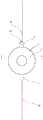
图1为本发明实施例提供的超声雾化片的立体结构示意图;Figure 1 is a schematic diagram of the three-dimensional structure of the ultrasonic atomizing sheet provided by the embodiment of the present invention;
图2为图1所示的超声雾化片的主视结构示意图;Fig. 2 is a schematic diagram of the front view structure of the ultrasonic atomizing sheet shown in Fig. 1;
图3为图2所示的超声雾化片的剖视结构示意图;Fig. 3 is a schematic cross-sectional structure diagram of the ultrasonic atomizing sheet shown in Fig. 2;
图4为本发明实施例提供的第一金属片的结构示意图;4 is a schematic structural diagram of a first metal sheet provided by an embodiment of the present invention;
图5为本发明实施例提供的第二金属片的结构示意图;5 is a schematic structural diagram of a second metal sheet provided by an embodiment of the present invention;
图6为图1所示的超声雾化片的爆炸图。Fig. 6 is an exploded view of the ultrasonic atomizing sheet shown in Fig. 1 .
其中,图中各附图标记:Wherein, each reference sign in the figure:
1-压电陶瓷片;11-通孔;12-第一面;13-第二面;1-piezoelectric ceramic sheet; 11-through hole; 12-first surface; 13-second surface;
2-第一电极层;3-第二电极层;2-first electrode layer; 3-second electrode layer;
4-第一金属片;41-第一环孔;4-the first metal sheet; 41-the first ring hole;
5-第二金属片;51-第二环形保护片;52-金属膜片部分;53-第二环孔;5-the second metal sheet; 51-the second annular protection sheet; 52-the metal diaphragm part; 53-the second ring hole;
6-第一极耳;7-第二极耳;8-围边;9-陶瓷区域;6-first tab; 7-second tab; 8-surrounding edge; 9-ceramic area;
10-第一导电胶层;20-第二导电胶层;30-引线;40-焊点。10-the first conductive adhesive layer; 20-the second conductive adhesive layer; 30-leads; 40-soldering points.
具体实施方式Detailed ways
为了使本发明所要解决的技术问题、技术方案及有益效果更加清楚明白,以下结合附图及实施例,对本发明进行进一步详细说明。应当理解,此处所描述的具体实施例仅仅用以解释本发明,并不用于限定本发明。In order to make the technical problems, technical solutions and beneficial effects to be solved by the present invention clearer, the present invention will be further described in detail below in conjunction with the accompanying drawings and embodiments. It should be understood that the specific embodiments described here are only used to explain the present invention, not to limit the present invention.
需要说明的是,当元件被称为“连接于”或“设置于”另一个元件,它可以直接在另一个元件上或者间接在该另一个元件上。当一个元件被称为是“连接于”另一个元件,它可以是直接连接到另一个元件或间接连接至该另一个元件上。It should be noted that when an element is referred to as being “connected to” or “disposed on” another element, it may be directly on the other element or be indirectly on the other element. When an element is referred to as being "connected to" another element, it can be directly connected to the other element or indirectly connected to the other element.
此外,术语“第一”、“第二”仅用于描述目的,而不能理解为指示或暗示相对重要性或者隐含指明所指示的技术特征的数量。由此,限定有“第一”、“第二”的特征可以明示或者隐含地包括一个或者更多个该特征。在本发明的描述中,“多个”的含义是两个或两个以上,除非另有明确具体的限定。“若干”的含义是一个或一个以上,除非另有明确具体的限定。In addition, the terms "first" and "second" are used for descriptive purposes only, and cannot be interpreted as indicating or implying relative importance or implicitly specifying the quantity of indicated technical features. Thus, a feature defined as "first" and "second" may explicitly or implicitly include one or more of these features. In the description of the present invention, "plurality" means two or more, unless otherwise specifically defined. "Several" means one or more than one, unless otherwise clearly and specifically defined.
在本发明的描述中,需要理解的是,术语“中心”、“长度”、“宽度”、“厚度”、“上”、“下”、“前”、“后”、“左”、“右”、“竖直”、“水平”、“顶”、“底”、“内”、“外”等指示的方位或位置关系为基于附图所示的方位或位置关系,仅是为了便于描述本发明和简化描述,而不是指示或暗示所指的装置或元件必须具有特定的方位、以特定的方位构造和操作,因此不能理解为对本发明的限制。In describing the present invention, it should be understood that the terms "center", "length", "width", "thickness", "upper", "lower", "front", "rear", "left", " The orientation or positional relationship indicated by "right", "vertical", "horizontal", "top", "bottom", "inner", "outer", etc. is based on the orientation or positional relationship shown in the drawings, and is for convenience only The present invention is described and simplified descriptions do not indicate or imply that the device or element referred to must have a specific orientation, be constructed and operate in a specific orientation, and thus should not be construed as limiting the present invention.
在本发明的描述中,需要说明的是,除非另有明确的规定和限定,术语“安装”、“相连”、“连接”应做广义理解,例如,可以是固定连接,也可以是可拆卸连接,或一体地连接;可以是机械连接,也可以是电连接;可以是直接相连,也可以通过中间媒介间接相连,可以是两个元件内部的连通或两个元件的相互作用关系。对于本领域的普通技术人员而言,可以根据具体情况理解上述术语在本发明中的具体含义。In the description of the present invention, it should be noted that unless otherwise specified and limited, the terms "installation", "connection" and "connection" should be understood in a broad sense, for example, it can be a fixed connection or a detachable connection. Connection, or integral connection; can be mechanical connection or electrical connection; can be direct connection or indirect connection through an intermediary, and can be the internal communication of two elements or the interaction relationship between two elements. Those of ordinary skill in the art can understand the specific meanings of the above terms in the present invention according to specific situations.
在整个说明书中参考“一个实施例”或“实施例”意味着结合实施例描述的特定特征,结构或特性包括在本申请的至少一个实施例中。因此,“在一个实施例中”、“在一些实施例中”或“在其中一些实施例中”的短语出现在整个说明书的各个地方,并非所有的指代都是相同的实施例。此外,在一个或多个实施例中,可以以任何合适的方式组合特定的特征,结构或特性。Reference throughout this specification to "one embodiment" or "an embodiment" means that a particular feature, structure or characteristic described in connection with the embodiment is included in at least one embodiment of the present application. Thus, the phrases "in one embodiment," "in some embodiments," or "in some of these embodiments" appear in various places throughout the specification, not all referring to the same embodiments. Furthermore, the particular features, structures or characteristics may be combined in any suitable manner in one or more embodiments.
请一并参阅图1至图6,现对本发明实施例提供的超声雾化片进行说明。本发明实施例提供的超声雾化片适用于气溶胶发生装置的雾化器,该气溶胶发生装置包括雾化器以及与雾化器电性连接的电源装置(图未示出)。使用时,电源装置用于向雾化器的超声雾化片提供电能,超声雾化片的压电元件(压电陶瓷片1)在电驱动作用下,压电陶瓷片1通过逆压电效应可将电能转换为机械能,并发生反复形变而产生振动。在压电陶瓷片1振动的过程中,气溶胶形成基质就能够从微孔被挤压出去,进而形成微小颗粒的烟雾。Please refer to FIG. 1 to FIG. 6 together, and now describe the ultrasonic atomizing sheet provided by the embodiment of the present invention. The ultrasonic atomizing sheet provided by the embodiment of the present invention is suitable for an atomizer of an aerosol generating device, and the aerosol generating device includes an atomizer and a power supply device (not shown) electrically connected to the atomizer. When in use, the power supply device is used to provide electric energy to the ultrasonic atomizing sheet of the nebulizer. It can convert electrical energy into mechanical energy, and undergo repeated deformation to generate vibration. During the vibration of the piezoelectric ceramic sheet 1 , the aerosol-forming matrix can be squeezed out from the micropores, thereby forming a mist of fine particles.
请结合参阅图1、图2和图6,本发明实施例提供的超声雾化片包括压电陶瓷片1、第一电极层2、第二电极层3、第一金属片4和第二金属片5,压电陶瓷片1的居中位置贯穿设置有通孔11,压电陶瓷片1沿通孔11轴向的两端分别具有第一面12和第二面13。为了向压电陶瓷片1的第一面12和第二面13分别施加电压,以使得压电陶瓷片1产生振动,需要在压电陶瓷片1的第一面12上设置第一电极层2,在压电陶瓷片1的第二面13上设置第二电极层3。具体地,第一电极层2层叠设置于压电陶瓷片1的第一面12上,第一金属片4设于第一电极层2背离压电陶瓷片1的一面上,第一金属片4与第一电极层2电性相连。第二电极层3层叠设置于压电陶瓷片1的第二面13上,第二金属片5设于第二电极层3背离压电陶瓷片1的一面上,第二金属片5与第二电极层3电性相连,第二金属片5对应通孔11的位置开设有微孔。请结合参阅图2、图4和图5,第一金属片4上设有用于焊接引线30或用于供顶针抵接的第一极耳6,第二金属片5上设有用于焊接引线30或用于供顶针抵接的第二极耳7,第一极耳6的至少部分伸出压电陶瓷片1所在的区域,第二极耳7的至少部分伸出压电陶瓷片1所在的区域。则在使用时,仅需将两根引线30分别焊接于第一极耳6和第二极耳7上,就可以通过电源装置向压电陶瓷片1的第一面12和第二面13分别施加电压。这样,在超声雾化片工作时,由于第一极耳6和第二极耳7分别伸出压电陶瓷片1所在的区域,可保证焊点40均位于压电陶瓷片1的陶瓷区域9(陶瓷区域9是指图2中虚线内的区域)外,也就是说引线30无需直接焊接在压电陶瓷片1的陶瓷区域9内,从而消除了压电陶瓷在焊点40处受力明显增大而受力不均衡的缺陷,不仅避免压电陶瓷在焊点40处受力不均衡而影响压电陶瓷振动性能,而且可有效防止因压电陶瓷受力不均衡而造成压电陶瓷内部暗裂或直接破裂的问题出现。可以理解地,在通过顶针抵接于第一极耳6和/或第二极耳7上时,由于第一极耳6和第二极耳7分别伸出压电陶瓷片1所在的区域,可保证触点均位于压电陶瓷片1的陶瓷区域9外,也同样能够消除了压电陶瓷在焊点40处受力明显增大而受力不均衡的缺陷。Please refer to Fig. 1, Fig. 2 and Fig. 6. The ultrasonic atomizing sheet provided by the embodiment of the present invention includes a piezoelectric ceramic sheet 1, a first electrode layer 2, a
本发明实施例提供的超声雾化片,与现有技术相比,通过在第一电极层2上设置第一金属片4,在第一金属片4上设置伸出压电陶瓷片1所在的区域的第一极耳6,同时在第二电极层3上设置第二金属片5,并在第二金属片5上设置伸出压电陶瓷片1所在的区域的第二极耳7,仅需将电连接于电源装置正负极的两根引线30分别焊接于第一极耳6和第二极耳7伸出压电陶瓷片1所在区域的部分,就可以通过电源装置向压电陶瓷片1的第一面12和第二面13分别施加电压。这样,在超声雾化片工作时,由于第一极耳6和第二极耳7分别伸出压电陶瓷片1所在的区域,可保证焊点40均位于压电陶瓷片1的陶瓷区域9外,能够消除压电陶瓷在焊点40处受力明显增大而存在的受力不均衡的缺陷,不仅避免压电陶瓷在焊点40处受力不均衡而影响压电陶瓷振动性能,而且可有效防止因压电陶瓷受力不均衡而造成压电陶瓷内部暗裂或直接破裂的问题出现。Compared with the prior art, the ultrasonic atomizing sheet provided by the embodiment of the present invention is provided with the
请结合参阅图1和图6,在其中一些实施例中,压电陶瓷片1为圆环形,压电陶瓷片1的内环围合形成通孔11。在其中另一些实施例中,压电陶瓷片1可以为方形、椭圆形、菱形等形状,需要说明的是,无论压电陶瓷片1的形状如何,其中心都具贯通的通孔11。请结合参阅图1和图2,在其中一些实施例中,第一极耳6在垂直方向上的投影与第二极耳7在垂直方向上的投影不重合,也就是说第一极耳6与第二极耳7沿压电陶瓷片1的周向具有一定的间隔,方便超声雾化片的布线安装。Please refer to FIG. 1 and FIG. 6 together. In some embodiments, the piezoelectric ceramic sheet 1 is circular, and the inner ring of the piezoelectric ceramic sheet 1 encloses to form a through
请结合参阅图1、图4和图6,在其中一些实施例中,第一金属片4为第一环形保护片,第一环形保护片覆设于第一电极层2背离压电陶瓷片1的一面上,也就是说,第一环形保护片与第一电极层2的形状与尺寸完全相同,以充分保证第一环形保护片与第一电极层2完全重叠设置。当然,第一环形保护片与第一电极层2的形状与尺寸也可以不相同。可以理解地,第一环形保护片即第一金属片4,可以是但不限于不锈钢或钛。这样,通过第一环形保护片代替第一电极层2上的玻璃釉质保护层,又可以同时兼顾导电且同时保持了压电陶瓷片1的第一面12的完整性,有利于压电陶瓷片1的第一面12受力均衡。为了使得第一极耳6不在压电陶瓷片1所在的区域内,以保证引线30与第一极耳6的焊点40不在压电陶瓷片1所在的区域内,将第一极耳6设于第一环形保护片的外周,且第一极耳6沿通孔11的径向延伸,使得第一极耳6在垂直方向上的投影与压电陶瓷片1在垂直方向上的投影不重合,可保证焊点40均位于压电陶瓷片1的陶瓷区域9外,能够消除压电陶瓷在焊点40处受力明显增大而存在的受力不均衡的缺陷,不仅避免压电陶瓷在焊点40处受力不均衡而影响压电陶瓷振动性能,而且可有效防止因压电陶瓷受力不均衡而造成压电陶瓷内部暗裂或直接破裂的问题出现。可以理解地,请结合参阅图4,在其中一些实施例中,第一极耳6可以与第一环形保护片即第一金属片4一体成型。也就是说,当第一环形保护片即第一金属片4为不锈钢或钛等金属片时,可以是在第一环形保护片即第一金属片4延展出第一极耳6。Please refer to FIG. 1 , FIG. 4 and FIG. 6 in conjunction. In some embodiments, the
请结合参阅图1、图3和图6,在其中一些实施例中,第一环形保护片的第一环孔41与通孔11对应设置,第一环形保护片即第一金属片4上设有围边8,围边8由第一环孔41靠近压电陶瓷片1的一端并沿第一环孔41轴向延伸,围边8用于配合插入通孔11中以定位第一环形保护片。则在使用时,仅需将围边8插装于通孔11中,利用围边8与通孔11形成同心圆紧配的定位结构,在装配第一环形保护片与环形的压电陶瓷片1过程中,有利于第一环形保护片与环形的压电陶瓷片1保持良好的同心度进行装配,进而使得第一环形保护片与环形的压电陶瓷片1同心居中对位,能够保证压电陶瓷片1受力均衡。Please refer to Fig. 1, Fig. 3 and Fig. 6 in combination, in some of the embodiments, the first ring hole 41 of the first annular protection sheet is provided correspondingly to the through
请结合参阅图3、图5和图6,在其中一些实施例中,第二金属片5包括覆设于第二电极层3背离压电陶瓷片1的一面上的第二环形保护片51和设于第二环形保护片51的第二环孔53处的金属膜片部分52,微孔设于金属膜片部分52。第二环形保护片51与第二电极层3的形状与尺寸完全相同,以充分保证第二环形保护片51与第二电极层3完全重叠设置。当然,第二环形保护片51与第二电极层3的形状与尺寸也可以不相同。可以理解地,第二环形保护片51可以是但不限于不锈钢或钛。这样,通过第二环形保护片51代替第二电极层3上的玻璃釉质保护层,又可以同时兼顾导电且同时保持了压电陶瓷片1的第二面13的完整性,有利于压电陶瓷片1的第二面13受力均衡。为了使得第二极耳7不在压电陶瓷片1所在的区域内,以保证引线30与第二极耳7的焊点40不在压电陶瓷片1所在的区域内,将第二极耳7设于第二环形保护片51的外周,且第二极耳7沿通孔11的径向延伸,使得第二极耳7在垂直方向上的投影与压电陶瓷片1在垂直方向上的投影不重合,可保证焊点40均位于压电陶瓷片1的陶瓷区域9外,能够消除压电陶瓷在焊点40处受力明显增大而存在的受力不均衡的缺陷,不仅避免压电陶瓷在焊点40处受力不均衡而影响压电陶瓷振动性能,而且可有效防止因压电陶瓷受力不均衡而造成压电陶瓷内部暗裂或直接破裂的问题出现。可以理解地,请结合参阅图5,在其中一些实施例中,第二极耳7可以与第二环形保护片51一体成型。也就是说,当第二环形保护片51为不锈钢或钛等金属片时,可以是在第二环形保护片51延展出第二极耳7。Please refer to FIG. 3 , FIG. 5 and FIG. 6 . In some embodiments, the
请结合参阅图3和图6,在其中一些实施例中,第一金属片4为覆设于第一电极层2背离压电陶瓷片1的一面上的第一环形保护片,第二金属片5包括覆设于第二电极层3背离压电陶瓷片1的一面上的第二环形保护片51和设于第二环形保护片51的第二环孔53处且具有微孔的金属膜片部分52,第一环形保护片与第二环形保护片51对称设置。通过将第一环形保护片与第二环形保护片51进行对称设置,降低对压电陶瓷片1的额外应力,有利于压电陶瓷片1上的第一电极层2与第二电极层3完全对称且完整,使得高压极化后的压电陶瓷片1,在沿通孔11径向的振荡更均匀输出,从而使得压电陶瓷片1的振动更加稳定,有效防止因压电陶瓷受力不均衡而造成压电陶瓷内部暗裂或直接破裂。Please refer to FIG. 3 and FIG. 6 in conjunction. In some embodiments, the
请结合参阅图6,在其中一些实施例中,超声雾化片还包括用于结合第一电极层2与第一金属片4的第一导电胶层10。在第一电极层2镀设或印刷于压电陶瓷片1的第一面12上后,在第一电极层2背离压电陶瓷片1的一面上涂抹导电胶,将第一金属片4结合于第一电极层2上,并在第一电极层2与第一金属片4之间形成第一导电胶层10。Please refer to FIG. 6 , in some embodiments, the ultrasonic atomizing sheet further includes a first conductive
请结合参阅图6,在其中一些实施例中,超声雾化片还包括用于结合第二电极层3与第二金属片5的第二导电胶层20。在第二电极层3镀设或印刷于压电陶瓷片1的第二面13上后,在第二电极层3背离压电陶瓷片1的一面上涂抹导电胶,将第二金属片5结合于第二电极层3上,并在第二电极层3与第二金属片5之间形成第二导电胶层20。需要说明的是,第一导电胶层10和/或第二导电胶层20可以是但不限于导电银胶层,也就是说导电胶可以是但不限于导电银胶,例如导电胶还可以是导电铜胶。Please refer to FIG. 6 , in some embodiments, the ultrasonic atomizing sheet further includes a second conductive
在其中一些实施例中,第一电极层2可以是但不限于镀设或印刷于压电陶瓷片1的第一面12上的第一导电银层,第一电极层2还可以是设于压电陶瓷片1的第一面12上的第一导电金层或第一导电铜层等。第二电极层3可以是但不限于镀设或印刷于第二面13上的第二导电银层。第二电极层3还可以是设于压电陶瓷片1的第二面13上的第二导电金层或第二导电铜层等。In some of these embodiments, the first electrode layer 2 may be, but not limited to, a first conductive silver layer plated or printed on the
本发明实施例还提供一种雾化器,该雾化器包括上述任一实施例提供的超声雾化片。由于雾化器具有上述任一实施例中提供的超声雾化片的全部技术特征,故其具有与上述超声雾化片相同的技术效果。An embodiment of the present invention also provides an atomizer, which includes the ultrasonic atomizing sheet provided in any one of the above embodiments. Since the atomizer has all the technical features of the ultrasonic atomizing sheet provided in any of the above-mentioned embodiments, it has the same technical effect as the above-mentioned ultrasonic atomizing sheet.
本发明实施例还提供一种气溶胶发生装置,该溶胶发生装置包括上述任一实施例提供的超声雾化片或雾化器。由于气溶胶发生装置具有上述任一实施例中提供的超声雾化片或雾化器的全部技术特征,故其具有与上述超声雾化片或雾化器相同的技术效果。An embodiment of the present invention also provides an aerosol generating device, the aerosol generating device includes the ultrasonic atomizing sheet or atomizer provided in any one of the above embodiments. Since the aerosol generating device has all the technical features of the ultrasonic atomizing sheet or atomizer provided in any of the above-mentioned embodiments, it has the same technical effect as the above-mentioned ultrasonic atomizing sheet or atomizer.
以上所述仅为本发明的较佳实施例而已,并不用以限制本发明,凡在本发明的精神和原则之内所作的任何修改、等同替换和改进等,均应包含在本发明的保护范围之内。The above descriptions are only preferred embodiments of the present invention, and are not intended to limit the present invention. Any modifications, equivalent replacements and improvements made within the spirit and principles of the present invention should be included in the protection of the present invention. within range.
Claims (10)
Translated fromChinesePriority Applications (1)
| Application Number | Priority Date | Filing Date | Title |
|---|---|---|---|
| CN202111569102.1ACN116268601A (en) | 2021-12-21 | 2021-12-21 | Ultrasonic atomizing sheet, atomizer and aerosol generating device |
Applications Claiming Priority (1)
| Application Number | Priority Date | Filing Date | Title |
|---|---|---|---|
| CN202111569102.1ACN116268601A (en) | 2021-12-21 | 2021-12-21 | Ultrasonic atomizing sheet, atomizer and aerosol generating device |
Publications (1)
| Publication Number | Publication Date |
|---|---|
| CN116268601Atrue CN116268601A (en) | 2023-06-23 |
Family
ID=86782043
Family Applications (1)
| Application Number | Title | Priority Date | Filing Date |
|---|---|---|---|
| CN202111569102.1APendingCN116268601A (en) | 2021-12-21 | 2021-12-21 | Ultrasonic atomizing sheet, atomizer and aerosol generating device |
Country Status (1)
| Country | Link |
|---|---|
| CN (1) | CN116268601A (en) |
Citations (5)
| Publication number | Priority date | Publication date | Assignee | Title |
|---|---|---|---|---|
| WO2015051580A1 (en)* | 2013-10-10 | 2015-04-16 | 肇庆捷成电子科技有限公司 | Piezoelectric ceramic sounding element and manufacturing method therefor |
| CN209222499U (en)* | 2018-11-05 | 2019-08-09 | 东莞市谦合电子有限公司 | A kind of piezoelectric ceramic atomizer patch |
| CN111451072A (en)* | 2020-04-23 | 2020-07-28 | 苏州云华睿和智能科技有限公司 | Ultrasonic atomizing device and laundry treatment equipment having the same |
| CN213762577U (en)* | 2020-12-02 | 2021-07-23 | 华清创智光电科技(清远)有限公司 | A kind of atomizing sheet with double-sided stepped aperture distribution |
| CN216701676U (en)* | 2021-12-21 | 2022-06-10 | 深圳市卓尔悦电子科技有限公司 | Ultrasonic atomization sheet, atomizer and aerosol generating device |
- 2021
- 2021-12-21CNCN202111569102.1Apatent/CN116268601A/enactivePending
Patent Citations (5)
| Publication number | Priority date | Publication date | Assignee | Title |
|---|---|---|---|---|
| WO2015051580A1 (en)* | 2013-10-10 | 2015-04-16 | 肇庆捷成电子科技有限公司 | Piezoelectric ceramic sounding element and manufacturing method therefor |
| CN209222499U (en)* | 2018-11-05 | 2019-08-09 | 东莞市谦合电子有限公司 | A kind of piezoelectric ceramic atomizer patch |
| CN111451072A (en)* | 2020-04-23 | 2020-07-28 | 苏州云华睿和智能科技有限公司 | Ultrasonic atomizing device and laundry treatment equipment having the same |
| CN213762577U (en)* | 2020-12-02 | 2021-07-23 | 华清创智光电科技(清远)有限公司 | A kind of atomizing sheet with double-sided stepped aperture distribution |
| CN216701676U (en)* | 2021-12-21 | 2022-06-10 | 深圳市卓尔悦电子科技有限公司 | Ultrasonic atomization sheet, atomizer and aerosol generating device |
Similar Documents
| Publication | Publication Date | Title |
|---|---|---|
| CN110719554B (en) | Sound production device and electronic equipment thereof | |
| JP5288080B1 (en) | Directional speaker | |
| CN110662155B (en) | Sound production device and assembly method thereof | |
| CN109936800B (en) | Manufacturing method of voice coil assembly and loudspeaker | |
| WO2023023997A1 (en) | Battery | |
| CN116268601A (en) | Ultrasonic atomizing sheet, atomizer and aerosol generating device | |
| CN209222499U (en) | A kind of piezoelectric ceramic atomizer patch | |
| CN216701676U (en) | Ultrasonic atomization sheet, atomizer and aerosol generating device | |
| WO2018045717A1 (en) | Loudspeaker body, loudspeaker module and sound production device | |
| CN204859539U (en) | Silicone diaphragm and speaker module | |
| CN204616070U (en) | Silicone diaphragm and speaker module | |
| TWM637254U (en) | Electroacoustic device and its pcb end cap | |
| JP2019536595A (en) | Lug terminal and ultrasonic scaler using it | |
| CN208462051U (en) | Loudspeaker and loudspeaker mould group | |
| CN208079029U (en) | A kind of energy trap type piezoelectric resonance device and atomizer | |
| JP2017076674A (en) | Substrate holding device | |
| CN216701683U (en) | Ultrasonic atomization sheet, atomizer and aerosol generating device | |
| CN115334427B (en) | Packaging structure, assembly structure and electronic equipment | |
| TWI863020B (en) | Electroacoustic device and its pcb end cap | |
| CN111010637A (en) | A Back Entry Microphone with Double Pads | |
| CN223041939U (en) | Atomization module and drug delivery device containing the same | |
| CN219938528U (en) | Loudspeaker assembly | |
| CN218387879U (en) | Electroacoustic device and circuit board end cover thereof | |
| CN219938530U (en) | Loudspeaker assembly | |
| CN222366388U (en) | A planar diaphragm speaker |
Legal Events
| Date | Code | Title | Description |
|---|---|---|---|
| PB01 | Publication | ||
| PB01 | Publication | ||
| SE01 | Entry into force of request for substantive examination | ||
| SE01 | Entry into force of request for substantive examination |