CN116256724A - Detection unit, detection array motherboard, detector and laser radar - Google Patents
Detection unit, detection array motherboard, detector and laser radarDownload PDFInfo
- Publication number
- CN116256724A CN116256724ACN202111503333.2ACN202111503333ACN116256724ACN 116256724 ACN116256724 ACN 116256724ACN 202111503333 ACN202111503333 ACN 202111503333ACN 116256724 ACN116256724 ACN 116256724A
- Authority
- CN
- China
- Prior art keywords
- microlens
- detection unit
- photosensitive
- unit according
- array
- Prior art date
- Legal status (The legal status is an assumption and is not a legal conclusion. Google has not performed a legal analysis and makes no representation as to the accuracy of the status listed.)
- Pending
Links
Images


Classifications
- G—PHYSICS
- G01—MEASURING; TESTING
- G01S—RADIO DIRECTION-FINDING; RADIO NAVIGATION; DETERMINING DISTANCE OR VELOCITY BY USE OF RADIO WAVES; LOCATING OR PRESENCE-DETECTING BY USE OF THE REFLECTION OR RERADIATION OF RADIO WAVES; ANALOGOUS ARRANGEMENTS USING OTHER WAVES
- G01S7/00—Details of systems according to groups G01S13/00, G01S15/00, G01S17/00
- G01S7/48—Details of systems according to groups G01S13/00, G01S15/00, G01S17/00 of systems according to group G01S17/00
- G01S7/481—Constructional features, e.g. arrangements of optical elements
- G01S7/4816—Constructional features, e.g. arrangements of optical elements of receivers alone
- G—PHYSICS
- G01—MEASURING; TESTING
- G01S—RADIO DIRECTION-FINDING; RADIO NAVIGATION; DETERMINING DISTANCE OR VELOCITY BY USE OF RADIO WAVES; LOCATING OR PRESENCE-DETECTING BY USE OF THE REFLECTION OR RERADIATION OF RADIO WAVES; ANALOGOUS ARRANGEMENTS USING OTHER WAVES
- G01S17/00—Systems using the reflection or reradiation of electromagnetic waves other than radio waves, e.g. lidar systems
- G01S17/02—Systems using the reflection of electromagnetic waves other than radio waves
- G01S17/06—Systems determining position data of a target
- G01S17/08—Systems determining position data of a target for measuring distance only
- G—PHYSICS
- G01—MEASURING; TESTING
- G01S—RADIO DIRECTION-FINDING; RADIO NAVIGATION; DETERMINING DISTANCE OR VELOCITY BY USE OF RADIO WAVES; LOCATING OR PRESENCE-DETECTING BY USE OF THE REFLECTION OR RERADIATION OF RADIO WAVES; ANALOGOUS ARRANGEMENTS USING OTHER WAVES
- G01S7/00—Details of systems according to groups G01S13/00, G01S15/00, G01S17/00
- G01S7/48—Details of systems according to groups G01S13/00, G01S15/00, G01S17/00 of systems according to group G01S17/00
- G01S7/481—Constructional features, e.g. arrangements of optical elements
- G01S7/4811—Constructional features, e.g. arrangements of optical elements common to transmitter and receiver
- H—ELECTRICITY
- H10—SEMICONDUCTOR DEVICES; ELECTRIC SOLID-STATE DEVICES NOT OTHERWISE PROVIDED FOR
- H10F—INORGANIC SEMICONDUCTOR DEVICES SENSITIVE TO INFRARED RADIATION, LIGHT, ELECTROMAGNETIC RADIATION OF SHORTER WAVELENGTH OR CORPUSCULAR RADIATION
- H10F39/00—Integrated devices, or assemblies of multiple devices, comprising at least one element covered by group H10F30/00, e.g. radiation detectors comprising photodiode arrays
- H10F39/011—Manufacture or treatment of image sensors covered by group H10F39/12
- H10F39/024—Manufacture or treatment of image sensors covered by group H10F39/12 of coatings or optical elements
- H—ELECTRICITY
- H10—SEMICONDUCTOR DEVICES; ELECTRIC SOLID-STATE DEVICES NOT OTHERWISE PROVIDED FOR
- H10F—INORGANIC SEMICONDUCTOR DEVICES SENSITIVE TO INFRARED RADIATION, LIGHT, ELECTROMAGNETIC RADIATION OF SHORTER WAVELENGTH OR CORPUSCULAR RADIATION
- H10F39/00—Integrated devices, or assemblies of multiple devices, comprising at least one element covered by group H10F30/00, e.g. radiation detectors comprising photodiode arrays
- H10F39/80—Constructional details of image sensors
- H10F39/806—Optical elements or arrangements associated with the image sensors
- H10F39/8063—Microlenses
- H—ELECTRICITY
- H10—SEMICONDUCTOR DEVICES; ELECTRIC SOLID-STATE DEVICES NOT OTHERWISE PROVIDED FOR
- H10F—INORGANIC SEMICONDUCTOR DEVICES SENSITIVE TO INFRARED RADIATION, LIGHT, ELECTROMAGNETIC RADIATION OF SHORTER WAVELENGTH OR CORPUSCULAR RADIATION
- H10F39/00—Integrated devices, or assemblies of multiple devices, comprising at least one element covered by group H10F30/00, e.g. radiation detectors comprising photodiode arrays
- H10F39/80—Constructional details of image sensors
- H10F39/806—Optical elements or arrangements associated with the image sensors
- H10F39/8067—Reflectors
- H—ELECTRICITY
- H10—SEMICONDUCTOR DEVICES; ELECTRIC SOLID-STATE DEVICES NOT OTHERWISE PROVIDED FOR
- H10F—INORGANIC SEMICONDUCTOR DEVICES SENSITIVE TO INFRARED RADIATION, LIGHT, ELECTROMAGNETIC RADIATION OF SHORTER WAVELENGTH OR CORPUSCULAR RADIATION
- H10F39/00—Integrated devices, or assemblies of multiple devices, comprising at least one element covered by group H10F30/00, e.g. radiation detectors comprising photodiode arrays
- H10F39/80—Constructional details of image sensors
- H10F39/804—Containers or encapsulations
- Y—GENERAL TAGGING OF NEW TECHNOLOGICAL DEVELOPMENTS; GENERAL TAGGING OF CROSS-SECTIONAL TECHNOLOGIES SPANNING OVER SEVERAL SECTIONS OF THE IPC; TECHNICAL SUBJECTS COVERED BY FORMER USPC CROSS-REFERENCE ART COLLECTIONS [XRACs] AND DIGESTS
- Y02—TECHNOLOGIES OR APPLICATIONS FOR MITIGATION OR ADAPTATION AGAINST CLIMATE CHANGE
- Y02A—TECHNOLOGIES FOR ADAPTATION TO CLIMATE CHANGE
- Y02A90/00—Technologies having an indirect contribution to adaptation to climate change
- Y02A90/10—Information and communication technologies [ICT] supporting adaptation to climate change, e.g. for weather forecasting or climate simulation
Landscapes
- Engineering & Computer Science (AREA)
- Physics & Mathematics (AREA)
- Computer Networks & Wireless Communication (AREA)
- General Physics & Mathematics (AREA)
- Radar, Positioning & Navigation (AREA)
- Remote Sensing (AREA)
- Electromagnetism (AREA)
- Solid State Image Pick-Up Elements (AREA)
Abstract
Translated fromChinese
Description
Translated fromChinese技术领域technical field
本发明涉及光探测领域,特别涉及一种探测单元、探测阵列、探测阵列母板、探测器和激光雷达。The invention relates to the field of light detection, in particular to a detection unit, a detection array, a detection array motherboard, a detector and a laser radar.
背景技术Background technique
激光雷达是一种常用的测距传感器,具有探测距离远、分辨率高、受环境干扰小等特点,广泛应用于智能机器人、无人机、无人驾驶等领域。激光雷达的工作原理是利用激光往返于雷达和目标之间所用的时间,或者调频连续光在雷达和目标之间往返所产生的频移来评估目标的距离或速度等信息。Lidar is a commonly used ranging sensor, which has the characteristics of long detection distance, high resolution, and low environmental interference. It is widely used in intelligent robots, drones, unmanned driving and other fields. The working principle of lidar is to use the time it takes for the laser to go back and forth between the radar and the target, or the frequency shift caused by the frequency modulation continuous light going back and forth between the radar and the target to evaluate information such as the distance or speed of the target.
测远性能是激光雷达的一项重要技术指标。随着SiPM、SPAD等单光子探测器件引入激光雷达,由于其更强的光子探测能力、更高的灵敏度、更低的电子噪声,使其越来越受到业内人士的青睐。The distance measurement performance is an important technical indicator of lidar. With the introduction of single-photon detection devices such as SiPM and SPAD into lidar, due to its stronger photon detection capability, higher sensitivity, and lower electronic noise, it has become more and more popular in the industry.
采用SiPM、SPAD等单光子探测器件的感光像素中,感光区域的面积相比于像素面积小很多,即感光区域面积相比于像素面积的填充因子很小,而只有入射到感光区域的光信号才会被有效探测。这就限制了感光像素的探测效率。为了提升探测效率,通常会在感光像素表面设置微透镜阵列,将光聚焦在感光区域。In photosensitive pixels using single-photon detection devices such as SiPM and SPAD, the area of the photosensitive area is much smaller than the pixel area, that is, the fill factor of the photosensitive area is small compared to the pixel area, and only the light signal incident on the photosensitive area will be effectively detected. This limits the detection efficiency of the photosensitive pixels. In order to improve the detection efficiency, a microlens array is usually arranged on the surface of the photosensitive pixel to focus the light on the photosensitive area.
但是即使设置微透镜阵列,探测单元的探测效率依旧有待提高。However, even if the microlens array is provided, the detection efficiency of the detection unit still needs to be improved.
发明内容Contents of the invention
本发明解决的问题是提供一种探测单元、探测阵列、探测阵列母板、探测器和激光雷达,以提高探测单元的探测效率。The problem to be solved by the present invention is to provide a detection unit, a detection array, a detection array motherboard, a detector and a laser radar, so as to improve the detection efficiency of the detection unit.
为解决上述问题,本发明提供一种探测单元,包括:In order to solve the above problems, the present invention provides a detection unit, comprising:
感光像素,所述感光像素包括多个感光器件;微透镜阵列,所述微透镜阵列位于光入射所述感光像素的一侧,所述微透镜阵列包括多个微透镜,所述多个微透镜与所述多个感光器件一一对应;所述微透镜包括凸起部,所述凸起部的材料为无机材料。A photosensitive pixel, the photosensitive pixel includes a plurality of photosensitive devices; a microlens array, the microlens array is located on the side where light is incident on the photosensitive pixel, and the microlens array includes a plurality of microlenses, the plurality of microlenses One-to-one correspondence with the plurality of photosensitive devices; the microlens includes a raised portion, and the material of the raised portion is an inorganic material.
可选的,所述无机材料为硅。Optionally, the inorganic material is silicon.
可选的,所述微透镜阵列形成于所述感光像素的表面。Optionally, the microlens array is formed on the surface of the photosensitive pixel.
可选的,形成所述微透镜阵列的过程包括:沉积工艺。Optionally, the process of forming the microlens array includes: a deposition process.
可选的,所述微透镜为平面型微透镜。Optionally, the microlens is a planar microlens.
可选的,所述微透镜包括多个凸起部,所述微透镜为衍射型透镜。Optionally, the microlens includes a plurality of protrusions, and the microlens is a diffractive lens.
可选的,所述微透镜为菲涅尔波带片和超表面透镜中的至少一种。Optionally, the microlens is at least one of a Fresnel zone plate and a metasurface lens.
可选的,所述微透镜适宜于将光信号会聚至所对应感光器件的高电场区域。Optionally, the microlens is suitable for converging the optical signal to the high electric field area of the corresponding photosensitive device.
可选的,所述感光器件为背照式感光器件;所述感光器件具有设置电极的第一面以及与所述第一面相背的第二面;所述微透镜位于所述第二面的一侧。Optionally, the photosensitive device is a back-illuminated photosensitive device; the photosensitive device has a first surface provided with electrodes and a second surface opposite to the first surface; the microlens is located on the second surface side.
可选的,还包括:反射层,所述反射层位于所述感光器件的第一面。Optionally, further comprising: a reflective layer, the reflective layer is located on the first surface of the photosensitive device.
可选的,光信号依次透射所述微透镜阵列和所述感光器件后,在所述感光器件的第一面反射。Optionally, the light signal is reflected on the first surface of the photosensitive device after sequentially transmitting through the microlens array and the photosensitive device.
可选的,所述感光器件为正照式感光器件;所述感光器件具有设置电极的第一面以及与所述第一面相背的第二面;所述微透镜阵列位于所述第一面的一侧。Optionally, the photosensitive device is a front-illuminated photosensitive device; the photosensitive device has a first surface provided with electrodes and a second surface opposite to the first surface; the microlens array is located on the first surface side.
可选的,所述微透镜还包括:填充层,所述填充层位于所述感光器件的第一面上。Optionally, the microlens further includes: a filling layer, the filling layer is located on the first surface of the photosensitive device.
可选的,所述填充层的材料为低光损耗材料。Optionally, the material of the filling layer is a low optical loss material.
可选的,所述填充层的材料为氧化硅。Optionally, the material of the filling layer is silicon oxide.
可选的,还包括:包覆材料,所述包覆材料至少填充于相邻凸起部之间的空隙,所述包覆材料的折射率低于所述凸起部的材料的折射率。Optionally, it further includes: a covering material, the covering material at least fills the gaps between adjacent protrusions, and the refractive index of the covering material is lower than that of the material of the protrusions.
可选的,所述包覆材料的顶部表面高于所述凸起部的顶部表面。Optionally, the top surface of the covering material is higher than the top surface of the protrusion.
可选的,还包括:空气隙,所述空气隙至少位于相邻凸起部之间。Optionally, it further includes: an air gap, the air gap is located at least between adjacent protrusions.
可选的,还包括:封装层,所述封装层至少位于所述微透镜阵列上。Optionally, it further includes: an encapsulation layer, the encapsulation layer is located at least on the microlens array.
可选的,所述感光器件为单光子探测器件。Optionally, the photosensitive device is a single photon detection device.
可选的,所述微透镜适宜于将光信号会聚至所对应感光器件的耗尽层。Optionally, the microlens is suitable for converging the light signal to the depletion layer of the corresponding photosensitive device.
相应的,本发明还提供一种探测阵列,包括:呈阵列排布的探测单元,所述探测单元为本发明的探测单元。Correspondingly, the present invention also provides a detection array, comprising: detection units arranged in an array, and the detection units are the detection units of the present invention.
本发明还提供一种探测阵列母板,包括:多个探测阵列,所述探测阵列为本发明的探测阵列。The present invention also provides a detection array motherboard, comprising: a plurality of detection arrays, the detection arrays being the detection arrays of the present invention.
本发明还提供一种探测器,包括:至少一个探测阵列,所搜探测阵列为本发明的探测阵列。The present invention also provides a detector, including: at least one detection array, and the detected detection array is the detection array of the present invention.
本发明还提供一种激光雷达,包括:光源,所诉光源适宜于产生光线;探测器,所述探测器适宜于接收回波光,所述探测器为本发明的探测器。The present invention also provides a laser radar, comprising: a light source, the light source is suitable for generating light; a detector, the detector is suitable for receiving echo light, and the detector is the detector of the present invention.
与现有技术相比,本发明的技术方案具有以下优点:Compared with the prior art, the technical solution of the present invention has the following advantages:
本发明技术方案中,所述微透镜用以会聚光线的凸起部的材料为无机材料。所述凸起部的材料的折射率与所述探测单元的封装材料的折射率之间差异较大,因此能够在所述微透镜表面直接封装,即所述封装材料能够与所述微透镜表面接触,封装材料和微透镜之间无需保留空气隙,能够有效提高器件可靠性,降低封装难度;特别是针对车载设备,避免空气隙的形成有利于通过车规认证。In the technical solution of the present invention, the material of the protruding part of the microlens for converging light is an inorganic material. The difference between the refractive index of the material of the raised portion and the packaging material of the detection unit is relatively large, so it can be directly packaged on the surface of the microlens, that is, the packaging material can be combined with the surface of the microlens There is no need to keep an air gap between the contact and the packaging material and the microlens, which can effectively improve the reliability of the device and reduce the difficulty of packaging; especially for vehicle equipment, avoiding the formation of the air gap is conducive to passing the vehicle certification.
本发明可选方案中,所述微透镜阵列直接形成于所述感光像素的表面。所述微透镜阵列直接与所述感光像素集成,不仅能够有效提高器件集成度、提高器件稳定性,而且还能够减少后期装配步骤,降低装配难度。In an optional solution of the present invention, the microlens array is directly formed on the surface of the photosensitive pixel. The microlens array is directly integrated with the photosensitive pixels, which can not only effectively improve the integration degree of the device and improve the stability of the device, but also reduce the later assembly steps and reduce the difficulty of assembly.
本发明可选方案中,所述微透镜为平面型透镜,即所述微透镜中,所有凸起部的表面高度一致,光线透射的表面均为平面,光线透射的表面不是曲面,所述微透镜朝向封装材料的表面平行于所述感光像素的表面。采用平面型透镜,避免曲面能够有效保证制作工艺的可控性,能够有效保证微透镜的精度。In an optional solution of the present invention, the microlens is a planar lens, that is, in the microlens, the surface heights of all the protrusions are consistent, and the surfaces through which the light transmits are all planes, and the surfaces through which the light transmits are not curved surfaces. The surface of the lens facing the packaging material is parallel to the surface of the photosensitive pixel. The use of planar lenses and the avoidance of curved surfaces can effectively ensure the controllability of the manufacturing process and the precision of the microlenses.
附图说明Description of drawings
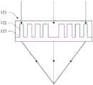
图1是一种探测单元的剖面结构示意图;Fig. 1 is a schematic cross-sectional structure diagram of a detection unit;
图2是本发明探测单元第一实施例的剖面结构示意图;Fig. 2 is a schematic cross-sectional structure diagram of the first embodiment of the detection unit of the present invention;
图3是图2所示探测单元中微透镜阵列内一个微透镜会聚光线的光路结构示意图;Fig. 3 is a schematic diagram of the optical path structure of a microlens converging light in the microlens array in the detection unit shown in Fig. 2;
图4是图3所示微透镜的放大结构示意图;Fig. 4 is the enlarged structure schematic diagram of microlens shown in Fig. 3;
图5是图3所示微透镜透射光线时光线的相位分布示意图;Fig. 5 is a schematic diagram of the phase distribution of light when the microlens shown in Fig. 3 transmits light;
图6是本发明探测单元第二实施例中微透镜透射光线时光线的相位分布示意图;6 is a schematic diagram of the phase distribution of the light rays transmitted by the microlens in the second embodiment of the detection unit of the present invention;
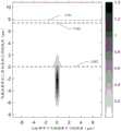
图7是图6所示探测单元实施例中超表面透镜内凸起部与传输相位之间的关系;Fig. 7 is the relationship between the convex part and the transmission phase in the metasurface lens in the embodiment of the detection unit shown in Fig. 6;
图8是本发明探测单元第三实施例的剖面结构示意图;Fig. 8 is a schematic cross-sectional structure diagram of the third embodiment of the detection unit of the present invention;
图9是图8所示探测单元实施例中微透镜对于平行入射的光线的聚焦情况;Fig. 9 is the focusing situation of the microlens for parallel incident rays in the detection unit embodiment shown in Fig. 8;
图10是本发明探测单元第四实施例的结构示意图;Fig. 10 is a schematic structural diagram of a fourth embodiment of the detection unit of the present invention;
图11是图10所示探测单元实施例中微透镜对于平行入射的光线的聚焦情况;Fig. 11 is the focusing situation of the microlens for parallel incident rays in the detection unit embodiment shown in Fig. 10;
图12是本发明探测单元第五实施例中微透镜对于平行入射的光线的聚焦情况。Fig. 12 is the focusing situation of the microlenses for parallel incident light rays in the fifth embodiment of the detection unit of the present invention.
具体实施方式Detailed ways
由背景技术可知,现有技术中即使设置了微透镜阵列,探测单元的探测效率依旧较低。现结合一种探测单元的结构分析其探测效率低问题的原因:It can be seen from the background art that even if a microlens array is provided in the prior art, the detection efficiency of the detection unit is still low. Now combine the structure of a detection unit to analyze the reasons for its low detection efficiency:
如图1所示,示出了一种探测单元的剖面结构示意图。As shown in FIG. 1 , a schematic cross-sectional structure diagram of a detection unit is shown.
所述探测单元包括:基板11;感光像素12,所述感光像素12位于所述基板11上,所述感光像素12的一侧和所述基板11通过导电银胶13实现连接和固定,所述感光像素12的另一侧和所述基板11内的互连结构14a通过连接线14连接;微透镜阵列15,所述微透镜阵列15位于所述感光像素12上。The detection unit includes: a
所述感光像素12包括多个感光器件(图中未示出)。所述感光器件为单光子感光器件,例如SPAD器件阵列或SiPM器件。所述微透镜阵列15包括多个微透镜,所述微透镜与所述感光器件一一对应,所述微透镜适宜于将光信号会聚至所对应感光器件的感光区域。The
所述微透镜阵列15通常采用光刻胶熔融技术(即立方体形状的光刻胶熔融后形成球形)、纳米压印技术等方法制备。这些制备方法对微透镜形貌和精度的控制精度较低,而且微透镜阵列还容易出现填充因子低于100%的问题,从而造成了微透镜阵列折射效果发生变化,光学性能不稳定,难以将光信号很好的会聚至感光器件的感光区域,从而引起了探测单元探测效率低下的问题。The
而且微透镜阵列无法完全填充、填充因子低于100%,也会使微透镜阵列、使探测单元中出现不可预计的空隙,从而引起器件的可靠性风险。Moreover, the microlens array cannot be completely filled, and the filling factor is lower than 100%, which will also cause unpredictable gaps in the microlens array and the detection unit, thereby causing reliability risks of the device.
另外,如图1所示,所述探测单元还包括:封装层16,所述封装层16覆盖所述基板11、所述感光像素12以及所述微透镜阵列。现有方法中,可靠性最好、成本最低的封装方案是基于有机材料的封装方案,即所述封装层16的材料是有机材料。而常用的光刻胶熔融技术(即立方体形状的光刻胶熔融后形成球形)、纳米压印技术等方法制备的微透镜阵列15的材料通常也是有机材料。In addition, as shown in FIG. 1 , the detection unit further includes: an
因此,所述微透镜阵列15的材料的折射率与所述封装层16的材料的折射率很接近,如果直接封装,即所述封装层16直接覆盖所述微透镜阵列15的表面,所述封装层16与所述微透镜阵列15的表面直接接触,会导致所述微透镜阵列15和所述封装层16界面两侧材料的折射率过于接近,从而影响甚至消除微透镜的折射作用,使微透镜会聚光线的能力削弱甚至失效。Therefore, the refractive index of the material of the
为了在实现封装的同时保证光学作用,所述微透镜阵列15和所述封装层16之间设置有空气隙17,即所述封装层16与所述微透镜阵列15起光学作用的表面并不直接接触,在所述封装层16下方,所述微透镜阵列15上方留有空气。但是空气受环境影响较大,空气隙17的存在会造成器件可靠性降低,而且也对封装工艺提出了很高的要求,增加了封装工艺的复杂度。In order to ensure the optical effect while realizing the encapsulation, an
尤其当所述探测单元应用于车载激光雷达时,空气隙17的存在对车规认证是一个较大的挑战。Especially when the detection unit is applied to a vehicle-mounted lidar, the existence of the
为解决所述技术问题,本发明提供一种探测单元,包括:In order to solve the technical problem, the present invention provides a detection unit, comprising:
感光像素,所述感光像素包括多个感光器件;微透镜阵列,所述微透镜阵列位于光入射所述感光像素光的一侧,所述微透镜阵列包括多个微透镜,所述微透镜与所述感光器件一一对应;所述微透镜包括凸起部,所述凸起部的材料为无机材料。A photosensitive pixel, the photosensitive pixel includes a plurality of photosensitive devices; a microlens array, the microlens array is located on the side where the light is incident on the photosensitive pixel, and the microlens array includes a plurality of microlenses, the microlens and There is one-to-one correspondence between the photosensitive devices; the microlens includes a raised portion, and the material of the raised portion is an inorganic material.
本发明技术方案,用以会聚光线的凸起部的材料为无机材料。所述凸起部的材料的折射率与所述探测单元的封装材料的折射率之间差异较大,因此能够在所述微透镜表面直接封装,即所述封装材料能够与所述微透镜表面直接接触,封装材料和微透镜之间无需保留空气隙,能够有效提高器件可靠性,降低封装难度;特别是针对车载设备,避免空气隙的形成有利于通过车规认证。In the technical solution of the present invention, the material of the raised portion used to condense the light is an inorganic material. The difference between the refractive index of the material of the raised portion and the packaging material of the detection unit is relatively large, so it can be directly packaged on the surface of the microlens, that is, the packaging material can be combined with the surface of the microlens In direct contact, there is no need to keep an air gap between the packaging material and the microlens, which can effectively improve the reliability of the device and reduce the difficulty of packaging; especially for automotive equipment, avoiding the formation of the air gap is conducive to passing the vehicle certification.
为使本发明的上述目的、特征和优点能够更为明显易懂,下面结合附图对本发明的具体实施例做详细的说明。In order to make the above objects, features and advantages of the present invention more comprehensible, specific embodiments of the present invention will be described in detail below in conjunction with the accompanying drawings.
参考图2,示出了本发明探测单元一实施例的剖面结构示意图。Referring to FIG. 2 , it shows a schematic cross-sectional structure diagram of an embodiment of the detection unit of the present invention.
所述探测单元包括:感光像素110,所述感光像素110包括多个感光器件(图中未示出);微透镜阵列120,所述微透镜阵列120位于光入射所述感光像素110的一侧,所述微透镜阵列120包括多个微透镜121,所述微透镜121与所述感光器件一一对应;所述微透镜121包括凸起部122,所述凸起部122的材料为无机材料。The detection unit includes: a
用以会聚光线的凸起部122的材料为无机材料。所述凸起部122的材料的折射率与所述探测单元的封装材料的折射率之间差异较大,因此所述微透镜121表面能够直接进行封装而不会影响其光学性能,即所述微透镜121表面能够直接与封装材料接触而不影响光学性能,所述微透镜121和封装材料之间无需保留空气隙,能够有效提高器件可靠性,降低封装难度;特别是针对车载设备,避免空气隙的形成有利于通过车规认证。The material of the protruding
所述感光像素110适宜于接收光信号并对光信号进行光电转换。所述感光像素110包括多个感光器件,所述多个感光器件呈阵列排布。The
本发明一些实施例中,所述感光器件为单光子探测器件。具体的,所述感光器件包括:SPAD器件。SPAD(Single Photon Avalanche Diode)器件,即单光子雪崩二极管,是工作在盖革模式下的雪崩光电二极管,可以用于对弱光信号甚至单光子信号的探测。作为光电探测器的应用形式主要是SPAD阵列或硅光电倍增管(Silicon photomultiplier,SiPM)。In some embodiments of the present invention, the photosensitive device is a single photon detection device. Specifically, the photosensitive device includes: a SPAD device. SPAD (Single Photon Avalanche Diode) device, that is, single photon avalanche diode, is an avalanche photodiode working in Geiger mode, which can be used to detect weak light signals or even single photon signals. The application form as a photodetector is mainly a SPAD array or a silicon photomultiplier (Silicon photomultiplier, SiPM).
本发明一些实施例中,所述感光像素110位于基板101上,所述感光像素110的一侧和所述基板101通过导电银胶102实现连接和固定,所述感光像素110的另一侧和所述基板101内的互连结构103通过连接线104连接。In some embodiments of the present invention, the
所述微透镜阵列120适宜于调整入射至所述感光像素110的光线。The
具体的,所述微透镜阵列120包括呈阵列排布的多个微透镜。所述多个微透镜与所述多个感光器件一一对应,即所述微透镜适宜于调整入射至所对应感光器件的光线。Specifically, the
所述微透镜包括凸起部122。所述凸起部122适宜于会聚光线。具体的,所述凸起部122的材料为无机材料。所述凸起部122与后期封装过程中所采用的封装材料的折射率相差很大,因此即使所述凸起部122与封装材料直接接触也不会影响其光学性能,也就是说,可以在所述微透镜121的凸起部122的表面直接封装,无需保留空气隙。The microlens includes a raised
本发明一些实施例中,所述感光器件为单光子探测器,因此所述微透镜阵列120中的微透镜适宜于将透射的光信号会聚至所对应感光器件的耗尽层。单光子探测器表面适于透射光信号的区域为光敏面,光敏面周围需要制备电极、光隔离结构等部件,因此感光器件的光敏面相比于所述感光器件的总表面积所得的填充因子比较小,但是只有透过光敏面入射至所述感光区域(即耗尽层)的光子才会被感光器件有效探测。所以所述微透镜的设置能够有效提高入射至对应感光器件的耗尽层的光的强度,以提高单光子探测器的探测效率。In some embodiments of the present invention, the photosensitive device is a single photon detector, so the microlenses in the
本发明一些实施例中,所述无机材料为硅(折射率3.5左右)。采用硅材料制作所述凸起部122,能够通过波段选择以尽量降低光损耗;而且将所述凸起部122的材料设置为硅,能够与所述感光像素110的制作工艺相兼容,能够在同一工艺流程中制作所述感光像素110和所述微透镜阵列120。In some embodiments of the present invention, the inorganic material is silicon (with a refractive index of about 3.5). Using silicon material to make the raised
需要说明的是,本发明一些实施例中,所述微透镜包括基底(图中未标示),所述凸起部122位于所述基底表面,且所述基底和所述凸起部122为一体结构。本发明另一些实施例中,所述微透镜也可以仅包括所述凸起部122。It should be noted that, in some embodiments of the present invention, the microlens includes a base (not shown in the figure), the raised
本发明一些实施例中,所述微透镜阵列120形成于所述感光像素110的表面,直接在所述感光像素110的表面形成所述微透镜阵列120,所述微透镜阵列120朝向所述感光像素110的表面与所述感光像素110朝向所述微透镜阵列120的表面直接接触。所述透镜阵列直接形成于所述感光像素110的表面。所述微透镜阵列120直接与所述感光像素110集成,不仅能够有效提高器件集成度、提高器件稳定性,而且还能够减少后期装配步骤,降低装配难度。In some embodiments of the present invention, the
本发明一些实施例中,所述探测单元还包括:包覆材料123,所述包覆材料123至少填充于相邻凸起部122之间的空隙,所述包覆材料123的折射率低于所述凸起部122的材料的折射率。所述包覆材料123填充于所述凸起部122之间起到保护增强的作用。具体的,所述包覆材料123的折射率低于所述凸起部122的材料的折射率,例如所述包覆材料123可以是聚合物或者硅化合物等。In some embodiments of the present invention, the detection unit further includes: a
本发明一些实施例中,所述包覆材料123的顶部表面高于所述凸起部122的顶部表面。使包覆材料123的顶部表面高于所述凸起部122的顶部表面,能够使所述包覆材料123完全覆盖所述凸起部122,从而能够有效保护所述凸起部,以便于后续封装。In some embodiments of the present invention, the top surface of the covering
本发明一些实施例中,所述探测单元还包括:封装层130,所述封装层至少位于所述微透镜阵列120上。所述封装层适宜于保护所述探测单元。本发明一些实施例中,所述凸起部之间填充的包覆层材料的顶部表面高于所述凸起部122的顶部表面,因此所述封装层与所述包覆材料123直接接触,即在所述包覆材料123表面直接进行封装。本发明另一些实施例中,所述包覆材料123露出所述凸起部122或者所述探测单元并不包括所述封装层时,所述封装材料与所述凸起部的表直接接触,即在所述微透镜阵列120的表面直接封装。In some embodiments of the present invention, the detection unit further includes: an
本发明一些实施例中,形成所述微透镜阵列120的过程包括:沉积工艺。具体的,形成所述微透镜阵列120的过程包括:在所述感光像素110表面沉积透镜材料层;在所述透镜材料层表面形成图案化层,所述图案化层暴露出所述透镜材料层的待刻蚀区域;以所述图案化层为掩膜,刻蚀所述微透镜材料层以形成具有所述凸起部的微透镜阵列120。一些实施例中,所述相邻凸起部122之间还填充有包覆材料123,因此刻蚀形成微透镜阵列120之后,还包括:在相邻凸起部之间填充包覆材料123。In some embodiments of the present invention, the process of forming the
如图2所示,本发明一些实施例中,所述微透镜为平面型微透镜,即所述微透镜中,所有凸起部的表面高度一致,光线透射的表面均为平面,光线透射的表面不是曲面。具体的,所述微透镜朝向封装材料的表面平行于所述感光像素110的表面。采用平面型透镜,避免曲面能够有效保证制作工艺的可控性,能够有效保证微透镜的精度。As shown in Figure 2, in some embodiments of the present invention, the microlens is a planar microlens, that is, in the microlens, the surface heights of all the protrusions are consistent, and the surfaces through which the light transmits are all planes, and the surfaces through which the light transmits Surfaces are not curved. Specifically, the surface of the microlens facing the packaging material is parallel to the surface of the
具体的,本发明一些实施例中,所述微透镜包括:多个凸起部122,所述微透镜为衍射型透镜,即光线在投射所述多个凸起部122过程中发生衍射以实现会聚效果。Specifically, in some embodiments of the present invention, the microlens includes: a plurality of raised
所述微透镜为衍射型透镜,所述微透镜不需要依靠表面折射率差所产生的折射作用,因此无论微透镜表面是空气还是折射率不同的封装材料,都不会影响其衍射作用,即所述微透镜的光学性能不受与其接触的材料影响,能够直接与封装材料接触。The microlens is a diffractive lens, and the microlens does not need to rely on the refraction effect produced by the difference in refractive index of the surface, so whether the surface of the microlens is air or a packaging material with a different refractive index, its diffraction effect will not be affected, that is The optical performance of the microlens is not affected by the material in contact with it, and can directly contact with the encapsulation material.
结合参考图3至图5,其中图3示出了图2所示探测单元中微透镜阵列120中一个微透镜会聚光线的光路结构示意图,图4示出了图3所示微透镜的放大结构示意图,图5示出了图3所示微透镜透射光线时光线的相位分布示意图。Referring to FIGS. 3 to 5 in conjunction, FIG. 3 shows a schematic view of the optical path structure of a microlens in the
本发明一些实施例中,所述微透镜121为菲涅尔波带片(Binary Fresnel ZonePlate,FZP)。菲涅尔波带片是由一系列不同半径、不同宽度的凸起的圆环构成。所述微透镜为菲涅尔波带片时,在平行于所述感光像素110表面的平面内,所述凸起部122的截面为圆环状,而且所述多个凸起部122呈同心圆环分布(如图5中小图501所示)。In some embodiments of the present invention, the
如图5所示,横轴表示所述凸起部122的截面半径,纵轴表示相位。线条502表示微透镜表面轮廓。具体的,结合图4,所述凸起部122顶部表面122a和所述凸起部122之间基底124表面124a之间相位差为π,即圆环顶部表面和圆环之间空隙底部表面之间相位差为π。As shown in FIG. 5 , the horizontal axis represents the section radius of the
所以,通过控制所示凸起部122凸起于基底124表面124a的高度h使所述凸起部122顶部表面122a和所述凸起部122之间基底124表面124a之间相位差满足预设要求。所述凸起部122顶部表面122a与所述凸起部122之间基底124表面124a之间的相位差与所述凸起部122凸起于基底124的高度h之间的关系为:Therefore, the phase difference between the

其中,n为所述凸起部122材料的折射率,n0为所述凸起部122之间空隙材料的折射率,λ为透射光线的波长。Wherein, n is the refractive index of the material of the raised
另外,所述凸起部122的半径为:In addition, the radius of the raised

其中,n为凸起部下方材料(如基底124)的折射率,k为圆环阶数。Wherein, n is the refractive index of the material (such as the substrate 124 ) under the protrusion, and k is the order of the ring.
具体的,图4中半径R1表示凸起部中1阶圆环的半径,即凸起部中,阶数k=1的圆环的半径,图4中半径R2表示凸起部中2阶圆环的半径,即凸起部中,阶数k=2的圆环的半径。半径R1和半径R2的具体大小可以根据上面Rk的公式获得。Specifically, the radius R1 in FIG. 4 represents the radius of the first-order ring in the raised portion, that is, the radius of the ring with order k=1 in the raised portion, and the radius R2 in FIG. 4 represents the second-order circle in the raised portion. The radius of the ring, that is, the radius of the circular ring with order k=2 in the raised portion. The specific sizes of the radius R1 and the radius R2 can be obtained according to the above formula of Rk .
参考图6,示出了本发明探测单元另一实施例中微透镜透射光线时光线的相位分布示意图。Referring to FIG. 6 , it shows a schematic diagram of phase distribution of light rays transmitted by microlenses in another embodiment of the detection unit of the present invention.
本发明一实施例中,所述微透镜还可以为超表面透镜(Metalens)。超表面透镜由周期性排列的不同截面尺寸的结构单元构成,每种结构单元对应一个不同的相位变化,根据目标空间相位分布在不同位置设置对应的结构单元。In an embodiment of the present invention, the microlens may also be a metasurface lens (Metalens). The metasurface lens is composed of periodically arranged structural units with different cross-sectional sizes. Each structural unit corresponds to a different phase change, and the corresponding structural units are set at different positions according to the target spatial phase distribution.
本发明一些实施例中,结构单元为圆柱或长方体。因此,所述微透镜为超表面透镜时,在平行所述感光像素表面的平面内,所述凸起部222的截面为圆形或长方形,所述多个凸起部222的截面尺寸并不相同。而且所述多个凸起部222以预设规律分布于平行所述感光像素表面的平面内(如图6中小图601所示)。In some embodiments of the present invention, the structural unit is a cylinder or a cuboid. Therefore, when the microlens is a metasurface lens, in a plane parallel to the surface of the photosensitive pixel, the cross-section of the raised
如图6中,以结构单元(凸起部222)为圆柱作为示意,横轴表示所述凸起部222中心与所述微透镜中心的距离,纵轴表示相位。线条602表示微透镜不同位置的相位。以r表示所述凸起部222中心与所述微透镜中心的距离,r处的相位为:As shown in FIG. 6 , the structural unit (protruding part 222 ) is shown as a cylinder, the horizontal axis represents the distance between the center of the

每一个所述凸起部222都会引起一个相位延迟,可以基于波导模型进行如下的理论计算:Each of the

其中,λ为透射光线的波长,neff为所述凸起部222中传输的基模的有效折射率,H为所述凸起部222的高度。Wherein, λ is the wavelength of the transmitted light, neff is the effective refractive index of the fundamental mode transmitted in the raised
每个所述凸起部222高度H相同,每个所述凸起部222所引起相位延迟的大小主要与所述凸起部222的截面尺寸有关(即所述凸起部222的截面尺寸影响neff)。The height H of each of the raised
结合参考图7,示出了图6所示探测单元实施例中超表面透镜中凸起部与传输相位之间的关系。Referring to FIG. 7 , the relationship between the convex portion and the transmission phase in the metasurface lens in the embodiment of the detection unit shown in FIG. 6 is shown.
具体的,所述微透镜的凸起部222为圆柱体,图7中横轴表示凸起部222的截面半径,纵轴表示传输相位,数据线701表示FDTD仿真的结果,数据线702表示波导模型计算结果。Specifically, the
需要说明的是,实际设计可以以仿真结果或基于上述公式理论计算为基准。或者,以仿真结果为基准,以波导模型计算结果为参考。It should be noted that the actual design can be based on simulation results or theoretical calculations based on the above formulas. Or, take the simulation results as a benchmark and the calculation results of the waveguide model as a reference.
由上述描述可知,本发明一些实施例的微透镜为衍射型透镜,微透镜的结构尺寸与透射光线的波长相关。根据感光器件所需感应的光线波长(工作波长),获得微透镜的结构尺寸,能够使得微透镜对于工作波长的入射光具有最佳的聚焦效果,工作波长以外的干扰光无法有效聚焦,从而能够降低干扰光对感应器件的影响。It can be seen from the above description that the microlenses in some embodiments of the present invention are diffractive lenses, and the structural size of the microlenses is related to the wavelength of the transmitted light. According to the light wavelength (working wavelength) that the photosensitive device needs to sense, the structural size of the microlens can be obtained, which can make the microlens have the best focusing effect on the incident light of the working wavelength, and the interfering light other than the working wavelength cannot be effectively focused, so that it can Reduce the impact of interfering light on sensing devices.
结合参考图6和图7,所述凸起部222的尺寸与所述凸起部222所处位置所需要的相位延迟相关,因此基于预设的焦距f和距离r,计算不同位置凸起部222所需的相位差,进而基于所述相位差获得所述凸起部222的截面尺寸。With reference to FIG. 6 and FIG. 7 , the size of the raised
需要说明的是,本发明一些实施例中,所述探测单元还包括:空气隙,所述空气隙至少位于相邻凸起部222之间。空气的折射率很低,在相邻凸起部222之间保留空气隙,在扩大凸起部222与周围环境之间的折射率差以保证良好光学性能的同时,工艺难度不高,对封装影响较低。It should be noted that, in some embodiments of the present invention, the detection unit further includes: an air gap, and the air gap is at least located between
还需要说明的是,本发明一些实施例中,所述微透镜的焦距大于所述感光器件的表面到耗尽层的距离。所述距离为耗尽层到感光器件表面的垂直距离。增大微透镜的焦距,在口径不变的情况下减小其数值孔径,有利于降低加工难度,提高微透镜的加工精度和聚焦效果。本发明的微透镜焦距相对较大,能够适用于背照式感光器件和正照式感光器件。It should also be noted that, in some embodiments of the present invention, the focal length of the microlens is greater than the distance from the surface of the photosensitive device to the depletion layer. The distance is the vertical distance from the depletion layer to the surface of the photosensitive device. Increasing the focal length of the microlens and reducing its numerical aperture while maintaining the same aperture will help reduce processing difficulty and improve the processing accuracy and focusing effect of the microlens. The focal length of the microlens of the present invention is relatively large, and can be applied to back-illuminated photosensitive devices and front-illuminated photosensitive devices.
参考图8,示出了本发明探测单元再一实施例的剖面结构示意图。Referring to FIG. 8 , it shows a schematic cross-sectional structure diagram of another embodiment of the detection unit of the present invention.
本发明一些实施例中,所述微透镜812适宜于将光信号会聚至所对应感光器件811的高电场区域813,也就是说,所述微透镜812的焦距满足预设条件,以使将光线会聚所对应感光器件811的高电场区域813。In some embodiments of the present invention, the
如图8所示,本发明一些实施例中,所述感光器件811为背照式(back sideillumination,BSI)感光器件811,也就是说,所述感光器件811的电极814位于一侧,光线从所述感光器件811的另一侧入射。所述高电场区域813位于感光器件811的耗尽层。As shown in FIG. 8, in some embodiments of the present invention, the
具体的,所述感光器件811具有设置电极814的第一面811a以及与所述第一面811a相背的第二面811b;所述微透镜阵列位于所述第二面811b的一侧。所以,所述感光器件811包括外延层815,所述外延层815适宜于吸收光子以实现探测;电极814,所述电极814位于所述外延层815一侧的表面;所述微透镜812位于所述外延层815远离所述电极814一侧的表面。光信号透射所述微透镜812后入射至所述外延层815,所述微透镜812将透射光线会聚至所述外延层815中的高电场区域813。Specifically, the
本发明一些实施例中,光信号依次透射所述微透镜阵列和所述感光器件811后,在所述感光器件811的第一面811a反射。光线入射至所述外延层815后,部分光信号被所述外延层815吸收以实现探测;部分光线透射所述外延层815设置所述电极814的一侧的表面发生反射,再次入射至所述外延层815以增加吸收探测的几率。In some embodiments of the present invention, the optical signal is reflected on the
本发明一些实施例中,所述探测单元还包括:反射层816,所述反射层816位于所述感光器件811的第一面811a。所述反射层816适宜于提高穿透感光器件811的光线在所述感光器件811的第一面811a发生反射的几率。In some embodiments of the present invention, the detection unit further includes: a
对于微透镜阵列来说,微透镜812往往口径大,焦距短,因此一般来说,微透镜阵列中的微透镜812往往具有较大的数值孔径(NA)。而大数值孔径的透镜的加工难度一般较大。但是,如图8所示实施例中,所述微透镜812的焦距使入射光经所述电极814或所述反射层816反射后再聚焦在焦点,从而可以在保持口径不变的情况下增大所述微透镜812焦距,从而能够有效减小所述微透镜812的数值孔径,进而降低所述微透镜812的加工难度。特别是当所述微透镜812为超表面透镜时,数值孔径的减小,还能有效改善所述微透镜812的透过率和聚焦效果。For a microlens array, the
结合参考图9,示出了图8所示探测单元实施例中所述微透镜812对于平行入射的光线的聚焦情况。Referring to FIG. 9 , it shows the focusing of parallel incident light by the
需要说明的是,图8所示实施例中,所述微透镜阵列中的微透镜812为超表面透镜。It should be noted that, in the embodiment shown in FIG. 8 , the
具体的,其中横轴表示所述凸起部中心与所述微透镜812中心的距离,纵轴表示与所述感光器件811光入射的表面之间的距离。图9中的虚线901和虚线902之间为超表面透镜所对应的区域,虚线902和虚线903之间为所述感光器件811中覆盖所述外延层815的介质层所对应的区域(所述介质层能够起到隔离保护、抗反射的作用,所述介质层的材料包括氧化硅、氮化硅中的至少一种),虚线903和虚线904之间为所述感光器件811的外延层815所对应的区域,虚线904和横轴之间为所述电极814所对应的区域。Specifically, the horizontal axis represents the distance between the center of the protrusion and the center of the
如图9所示,利用背照式感光器件811与电极814、反射层816的结合,能够有效延长所述微透镜812的焦距,使光线被电极814和反射层816反射后会聚至所述感光器件811外延层815的高电场区域813,所述微透镜812能够有效实现光线的聚焦作用。具体的,在背照式感光器件811与电极814、反射层816结合的实施例中,所述微透镜812的焦距应为感光器件811的外延层815的厚度与反射层816表面到高电场区域813之间距离之和。As shown in Figure 9, the combination of the back-illuminated
结合参考图10,示出了本发明探测单元另一实施例的结构示意图。Referring to FIG. 10 , a schematic structural diagram of another embodiment of the detection unit of the present invention is shown.
本发明一些实施例中,所述感光器件1011为正照式(front side illumination,FSI)感光器件,也就是说,光线从所述感光器件1011设置有电极1014的一侧入射。In some embodiments of the present invention, the
具体的,所述感光器件1011具有设置电极1014的第一面1011a以及与所述第一面1011a相背的第二面1011b;所述微透镜阵列位于所述第一面1011a的一侧。所以,所述感光器件1011的电极1014和所述微透镜阵列依次层叠于所述感光器件1011外延层的一侧表面上。光信号透射所述微透镜1012后入射至所述外延层,所述微透镜1012将透射光线会聚至所述外延层中的高电场区域1013。所述高电场区域1013位于感光器件1011的耗尽层。Specifically, the
需要说明的是,图10所示实施例中,所述感光器件1011具有2个电极,其中一个电极1014位于所述第一面1011a,另一个电极1014位于所述第二面1011b。FSI器件的电极1014与高电场区域1013之间有比较厚的衬底区域,光在衬底内传播过程中就会被完全吸收,无法被电极1014反射回高电场区域。It should be noted that, in the embodiment shown in FIG. 10 , the
如图10所示,本发明一些实施例中,所述微透镜1012还包括:填充层1016,所述填充层1016位于所述感光器件1011的第一面1011a上。所述填充层1016适宜于增大所述微透镜1012和所对应感光器件1011的高电场区域1013之间的距离,从而达到增大焦距、减小数值孔径的目的;而且还能够使会聚后的光线避开电极以提高探测效率。As shown in FIG. 10 , in some embodiments of the present invention, the
具体的,所述填充层1016的材料为低光损耗材料。采用低光损耗材料制备所述填充层1016,能够有效减小光线透射所述填充层1016时候的损耗,能够有效提高探测效率。例如,所述填充层1016的材料可以为氧化硅。氧化硅材料与所述感光器件1011和所述微透镜阵列的制作工艺兼容性高,能够有效降低填充层1016设置的影响。所述填充层1016的厚度根据所述微透镜1012的数值孔径和工艺限制决定,也就是说,基于工艺限制设计所述微透镜1012的数值孔径,以确定最短的焦距f,进而根据焦距f确定所述填充层1016的厚度,即焦距f减去感光器件1011表面到高电场区域的距离即为所述填充层1016的厚度。Specifically, the material of the
结合参考图11,示出了图10所示探测单元实施例中所述微透镜1012对于平行入射的光线的聚焦情况。Referring to FIG. 11 , it shows the focusing situation of the
需要说明的是,图10所示实施例中,所述微透镜阵列中的微透镜1012为超表面透镜。It should be noted that, in the embodiment shown in FIG. 10 , the
具体的,其中横轴表示所述凸起部中心与所述微透镜1012中心的距离,纵轴表示距离所述感光器件1011光入射的表面的距离。图11中的虚线1101和虚线1102之间为超表面透镜所对应的区域,虚线1102和虚线1103之间为所述填充层1016所对应的区域,虚线1103和横轴之间为所述感光器件1011的外延层所对应的区域。Specifically, the horizontal axis represents the distance between the center of the protrusion and the center of the
如图11所示,光线透射所述超表面透镜和所述填充层1016后,聚焦在所述感光器件1011的外延层,并在靠近所述外延层中所形成PN结的高电场区域,因而可以保证光信号被集中于所述高电场区域,能够有效增加光信号被吸收并激发载流子的概率,进而引发雪崩效应,能够有效提高光信号的有效探测。As shown in FIG. 11, after the light transmits through the metasurface lens and the
需要说明的是,前述实施例中,所述微透镜均为超表面微透镜。超表面透镜具有更高的聚焦效率,能够更有效的提高探测效率。但是将超表面微透镜与背照式感光器件相结合,或者将超表面微透镜与正照式感光器件相结合的做法,均为示意。本发明其他实施例中,与背照式感光器件相结合的微透镜或者与正照式感光器件相结合的微透镜也都可以是菲涅尔波带片。It should be noted that, in the foregoing embodiments, the microlenses are metasurface microlenses. The metasurface lens has a higher focusing efficiency and can improve the detection efficiency more effectively. However, the combination of the metasurface microlens and the back-illuminated photosensitive device, or the combination of the metasurface microlens and the front-illuminated photosensitive device are all illustrative. In other embodiments of the present invention, the microlens combined with the back-illuminated photosensitive device or the microlens combined with the front-illuminated photosensitive device may also be a Fresnel zone plate.
结合参考图12,示出了本发明再一探测单元实施例中所述微透镜对于平行入射的光线的聚焦情况。Referring to FIG. 12 , it shows the focusing situation of the microlenses for parallel incident light rays in still another embodiment of the detection unit of the present invention.
需要说明的是,图12所示实施例中,所述微透镜阵列中的微透镜为菲涅尔波带片;而且所述感光器件为正照式感光器件,所述微透镜和所述感光器件之间也设置有填充层。It should be noted that, in the embodiment shown in Fig. 12, the microlens in the microlens array is a Fresnel zone plate; and the photosensitive device is a positive photosensitive device, and the microlens and the photosensitive device Filling layers are also arranged between them.
具体的,其中横轴表示所述凸起部的半径,纵轴表示距离所述感光器件光入射的表面的距离。图12中的虚线1201和虚线1202之间为菲涅尔波带片所对应的区域,虚线1202和虚线1203之间为所述填充层所对应的区域,虚线1203和横轴之间为所述感光器件的外延层所对应的区域。Specifically, the horizontal axis represents the radius of the raised portion, and the vertical axis represents the distance from the light-incident surface of the photosensitive device. Between the dotted
如图12所示,所述菲涅尔波带片也能够使入射光线聚焦中高电场区域。菲涅尔波带片的尺寸更大,加工难度更低,能够有效提高良率。As shown in FIG. 12 , the Fresnel zone plate can also focus the incident light in the middle and high electric field region. The Fresnel zone plate is larger in size and less difficult to process, which can effectively improve the yield rate.
相应的,本发明还提供一种探测阵列,具体包括:呈阵列排布的探测单元,所述探测单元为本发明的探测单元。Correspondingly, the present invention also provides a detection array, which specifically includes: detection units arranged in an array, and the detection units are the detection units of the present invention.
所述探测单元为本发明的探测单元,因此所述探测单元的具体技术方案参考前述探测单元的实施例,本发明在此不再赘述。The detection unit is the detection unit of the present invention, so for the specific technical solution of the detection unit, refer to the foregoing embodiments of the detection unit, and the present invention will not repeat them here.
所述探测单元中的微透镜用以会聚光线的凸起部的材料为无机材料。所述凸起部的材料的折射率与所述探测单元的封装材料的折射率之间差异较大,因此能够在所述微透镜表面直接封装,即所述封装材料能够与所述微透镜表面接触,能够有效封装材料和微透镜之间无需保留空气隙,能够有效提高器件可靠性,降低封装难度;特别是针对车载设备,避免空气隙的形成有利于通过车规认证。The material of the protruding part of the microlens in the detection unit used to condense the light is an inorganic material. The difference between the refractive index of the material of the raised portion and the packaging material of the detection unit is relatively large, so it can be directly packaged on the surface of the microlens, that is, the packaging material can be combined with the surface of the microlens Contact can effectively improve the reliability of the device and reduce the difficulty of packaging without retaining an air gap between the packaging material and the microlens. Especially for vehicle-mounted equipment, avoiding the formation of air gaps is conducive to passing vehicle certification.
相应的,本发明还提供一种探测阵列母板,具体包括:多个探测阵列,所述探测阵列为本发明的探测阵列。Correspondingly, the present invention also provides a detection array motherboard, which specifically includes: a plurality of detection arrays, and the detection arrays are the detection arrays of the present invention.
所述探测阵列为本发明的探测阵列,因此所述探测阵列的具体技术方案参考前述探测阵列记载,本发明在此不再赘述。The detection array is the detection array of the present invention, so the specific technical solution of the detection array refers to the description of the detection array above, and the present invention will not repeat it here.
此外,本发明还提供一种探测器,包括:至少一个探测阵列,所述探测阵列为本发明的探测阵列。In addition, the present invention also provides a detector, including: at least one detection array, and the detection array is the detection array of the present invention.
所述探测阵列为本发明的探测阵列,因此所述探测阵列的具体技术方案参考前述探测阵列记载,本发明在此不再赘述。The detection array is the detection array of the present invention, so the specific technical solution of the detection array refers to the description of the detection array above, and the present invention will not repeat it here.
所述探测阵列中探测单元内的所述微透镜用以会聚光线的凸起部的材料为无机材料。所述凸起部的材料的折射率与所述探测单元的封装材料的折射率之间差异较大,因此能够在所述微透镜表面直接封装,即所述封装材料能够与所述微透镜表面接触,能够有效封装材料和微透镜之间无需保留空气隙,能够有效提高器件可靠性,降低封装难度;特别是针对车载设备,避免空气隙的形成有利于通过车规认证。The material of the protruding part of the microlens in the detection unit in the detection array used to condense the light is an inorganic material. The difference between the refractive index of the material of the raised portion and the packaging material of the detection unit is relatively large, so it can be directly packaged on the surface of the microlens, that is, the packaging material can be combined with the surface of the microlens Contact can effectively improve the reliability of the device and reduce the difficulty of packaging without retaining an air gap between the packaging material and the microlens. Especially for vehicle-mounted equipment, avoiding the formation of air gaps is conducive to passing vehicle certification.
所述探测器中探测阵列的封装无需保留空气隙,封装难度低、可靠性高,所述探测器更符合车规认证。The packaging of the detection array in the detector does not need to retain an air gap, the packaging difficulty is low, and the reliability is high, and the detector is more in line with the vehicle certification.
另外,本发明还提供一种激光雷达,所述激光雷达包括:光源,所述光源适宜于产生光线;探测器,所述探测器适宜于接收回波光,所述探测器为本发明的探测器。In addition, the present invention also provides a laser radar, which includes: a light source, the light source is suitable for generating light; a detector, the detector is suitable for receiving echo light, and the detector is the detector of the present invention .
综上,本发明技术方案中,所述微透镜用以会聚光线的凸起部的材料为无机材料。所述凸起部的材料的折射率与所述探测单元的封装材料的折射率之间差异较大,因此能够在所述微透镜表面直接封装,即所述封装材料能够与所述微透镜表面接触,能够有效封装材料和微透镜之间无需保留空气隙,能够有效提高器件可靠性,降低封装难度;特别是针对车载设备,避免空气隙的形成有利于通过车规认证。To sum up, in the technical solution of the present invention, the material of the raised portion of the microlens for converging light is an inorganic material. The difference between the refractive index of the material of the raised portion and the packaging material of the detection unit is relatively large, so it can be directly packaged on the surface of the microlens, that is, the packaging material can be combined with the surface of the microlens Contact can effectively improve the reliability of the device and reduce the difficulty of packaging without retaining an air gap between the packaging material and the microlens. Especially for vehicle-mounted equipment, avoiding the formation of air gaps is conducive to passing vehicle certification.
而且,所述微透镜阵列直接形成于所述感光像素的表面。所述微透镜阵列直接与所述感光像素集成,不仅能够有效提高器件集成度、提高器件稳定性,而且还能够减少后期装配步骤,降低装配难度。Moreover, the microlens array is directly formed on the surface of the photosensitive pixel. The microlens array is directly integrated with the photosensitive pixels, which can not only effectively improve the integration degree of the device and improve the stability of the device, but also reduce the later assembly steps and reduce the difficulty of assembly.
此外,所述微透镜为平面型透镜,即所述微透镜中,所有凸起部的表面高度一致,光线透射的表面均为平面,光线透射的表面不是曲面,所述微透镜朝向封装材料的表面平行于所述感光像素的表面。采用平面型透镜,避免曲面能够有效保证制作工艺的可控性,能够有效保证微透镜的精度。In addition, the microlens is a planar lens, that is, in the microlens, the surface heights of all the protrusions are consistent, and the surfaces through which the light is transmitted are all planes, and the surfaces through which the light is transmitted are not curved surfaces. The surface is parallel to the surface of the photosensitive pixel. The use of planar lenses and the avoidance of curved surfaces can effectively ensure the controllability of the manufacturing process and the precision of the microlenses.
虽然本发明披露如上,但本发明并非限定于此。任何本领域技术人员,在不脱离本发明的精神和范围内,均可作各种更动与修改,因此本发明的保护范围应当以权利要求所限定的范围为准。Although the present invention is disclosed above, the present invention is not limited thereto. Any person skilled in the art can make various changes and modifications without departing from the spirit and scope of the present invention, so the protection scope of the present invention should be based on the scope defined in the claims.
Claims (25)
Translated fromChinesePriority Applications (4)
| Application Number | Priority Date | Filing Date | Title |
|---|---|---|---|
| CN202111503333.2ACN116256724A (en) | 2021-12-09 | 2021-12-09 | Detection unit, detection array motherboard, detector and laser radar |
| PCT/CN2022/098331WO2023103314A1 (en) | 2021-12-09 | 2022-06-13 | Detection unit, detection array, detection array motherboard, detector, and laser radar |
| EP22902752.9AEP4446768A4 (en) | 2021-12-09 | 2022-06-13 | Detection unit, detection array, detection array main board, detector and laser radar |
| US18/736,831US20240355854A1 (en) | 2021-12-09 | 2024-06-07 | Detector unit, detector array, detector array motherboard, detector, and lidar |
Applications Claiming Priority (1)
| Application Number | Priority Date | Filing Date | Title |
|---|---|---|---|
| CN202111503333.2ACN116256724A (en) | 2021-12-09 | 2021-12-09 | Detection unit, detection array motherboard, detector and laser radar |
Publications (1)
| Publication Number | Publication Date |
|---|---|
| CN116256724Atrue CN116256724A (en) | 2023-06-13 |
Family
ID=86684879
Family Applications (1)
| Application Number | Title | Priority Date | Filing Date |
|---|---|---|---|
| CN202111503333.2APendingCN116256724A (en) | 2021-12-09 | 2021-12-09 | Detection unit, detection array motherboard, detector and laser radar |
Country Status (4)
| Country | Link |
|---|---|
| US (1) | US20240355854A1 (en) |
| EP (1) | EP4446768A4 (en) |
| CN (1) | CN116256724A (en) |
| WO (1) | WO2023103314A1 (en) |
Citations (4)
| Publication number | Priority date | Publication date | Assignee | Title |
|---|---|---|---|---|
| US6221687B1 (en)* | 1999-12-23 | 2001-04-24 | Tower Semiconductor Ltd. | Color image sensor with embedded microlens array |
| CN102157534A (en)* | 2010-01-15 | 2011-08-17 | 三星电子株式会社 | Unit picture elements, back-side illumination cmos image sensors including the unit picture elements and methods of manufacturing the unit picture elements |
| CN107195647A (en)* | 2017-04-25 | 2017-09-22 | 上海奕瑞光电子科技有限公司 | A kind of Amorphous silicon flat-panel detectors and preparation method thereof |
| WO2021196192A1 (en)* | 2020-04-03 | 2021-10-07 | 深圳市速腾聚创科技有限公司 | Laser transmission and reception system, lidar and self-driving device |
Family Cites Families (7)
| Publication number | Priority date | Publication date | Assignee | Title |
|---|---|---|---|---|
| KR101176545B1 (en)* | 2006-07-26 | 2012-08-28 | 삼성전자주식회사 | Method for forming micro-lens and image sensor comprising micro-lens and method for manufacturing the same |
| JP5342821B2 (en)* | 2008-07-16 | 2013-11-13 | パナソニック株式会社 | Solid-state image sensor |
| JP5702625B2 (en)* | 2011-02-22 | 2015-04-15 | ソニー株式会社 | Image sensor, image sensor manufacturing method, pixel design method, and electronic device |
| US10714520B1 (en)* | 2017-08-04 | 2020-07-14 | Facebook Technologies, Llc | Manufacturing an on-chip microlens array |
| CN113645376B (en)* | 2020-05-11 | 2023-05-26 | 宁波舜宇光电信息有限公司 | Microlens array camera module and manufacturing method thereof |
| CN112859046B (en)* | 2021-01-19 | 2024-01-12 | Oppo广东移动通信有限公司 | Light receiving modules, time-of-flight devices and electronic equipment |
| US11085609B1 (en)* | 2021-02-08 | 2021-08-10 | Himax Technologies Limited | Illumination device |
- 2021
- 2021-12-09CNCN202111503333.2Apatent/CN116256724A/enactivePending
- 2022
- 2022-06-13WOPCT/CN2022/098331patent/WO2023103314A1/ennot_activeCeased
- 2022-06-13EPEP22902752.9Apatent/EP4446768A4/enactivePending
- 2024
- 2024-06-07USUS18/736,831patent/US20240355854A1/enactivePending
Patent Citations (4)
| Publication number | Priority date | Publication date | Assignee | Title |
|---|---|---|---|---|
| US6221687B1 (en)* | 1999-12-23 | 2001-04-24 | Tower Semiconductor Ltd. | Color image sensor with embedded microlens array |
| CN102157534A (en)* | 2010-01-15 | 2011-08-17 | 三星电子株式会社 | Unit picture elements, back-side illumination cmos image sensors including the unit picture elements and methods of manufacturing the unit picture elements |
| CN107195647A (en)* | 2017-04-25 | 2017-09-22 | 上海奕瑞光电子科技有限公司 | A kind of Amorphous silicon flat-panel detectors and preparation method thereof |
| WO2021196192A1 (en)* | 2020-04-03 | 2021-10-07 | 深圳市速腾聚创科技有限公司 | Laser transmission and reception system, lidar and self-driving device |
Also Published As
| Publication number | Publication date |
|---|---|
| EP4446768A4 (en) | 2025-08-13 |
| EP4446768A1 (en) | 2024-10-16 |
| WO2023103314A1 (en) | 2023-06-15 |
| US20240355854A1 (en) | 2024-10-24 |
Similar Documents
| Publication | Publication Date | Title |
|---|---|---|
| US12148845B2 (en) | Photodetectors, preparation methods for photodetectors, photodetector arrays, and photodetection terminals | |
| US12261230B2 (en) | Single photon avalanche diode and manufacturing method, detector array, and image sensor | |
| US20220128661A1 (en) | Optical antenna, optical phased array transmitter, and lidar system using the same | |
| US20140339615A1 (en) | Bsi cmos image sensor | |
| US20140339606A1 (en) | Bsi cmos image sensor | |
| JP6082794B2 (en) | Image sensor device, CIS structure, and formation method thereof | |
| US20090250777A1 (en) | Image sensor and image sensor manufacturing method | |
| KR102805244B1 (en) | Image sensor and method for reducing image signal processor | |
| TW202210868A (en) | Tof optical sensing module for reducing in-chamber stray light interference | |
| KR100791842B1 (en) | Image sensor that does not require microlens shift and manufacturing method | |
| US20240339464A1 (en) | Pixel with an improved quantum efficiency | |
| TW202310378A (en) | Photodetector, manufacturing method for photodetector, and electronic device | |
| WO2022011694A1 (en) | Single photon avalanche diode and method for manufacturing same, and optical detection device and system | |
| TW202341453A (en) | Image sensor | |
| CN116256724A (en) | Detection unit, detection array motherboard, detector and laser radar | |
| TWM641749U (en) | Distance sensing module | |
| WO2023164944A1 (en) | Avalanche photon diode array chip, receiver, distance-measurement device and movable platform | |
| WO2025016449A1 (en) | LIGHT DETECTOR CHIP, LIGHT EMITTER CHIP, AND LiDAR | |
| JP6534888B2 (en) | Planar light detector | |
| TWI678518B (en) | Semiconductor optical sensor | |
| CN117936636A (en) | Light sensing chip and preparation method thereof, laser radar and electronic equipment | |
| CN117810235A (en) | image sensor | |
| CN119170613A (en) | Photoelectric sensor and method for forming the same, image sensor and method for forming the same | |
| CN118676221A (en) | Photoelectric sensor and method of forming the same | |
| CN115825927A (en) | Distance sensing module |
Legal Events
| Date | Code | Title | Description |
|---|---|---|---|
| PB01 | Publication | ||
| PB01 | Publication | ||
| SE01 | Entry into force of request for substantive examination | ||
| SE01 | Entry into force of request for substantive examination |