Movatterモバイル変換


[0]ホーム

URL:


CN116250900A - Rotary grinding system and driving handle thereof - Google Patents

Rotary grinding system and driving handle thereof
Download PDF

Info

Publication number
CN116250900A
CN116250900ACN202111510802.3ACN202111510802ACN116250900ACN 116250900 ACN116250900 ACN 116250900ACN 202111510802 ACN202111510802 ACN 202111510802ACN 116250900 ACN116250900 ACN 116250900A
Authority
CN
China
Prior art keywords
guide
sleeve
handle
atherectomy
drive
Prior art date
Legal status (The legal status is an assumption and is not a legal conclusion. Google has not performed a legal analysis and makes no representation as to the accuracy of the status listed.)
Pending
Application number
CN202111510802.3A
Other languages
Chinese (zh)
Inventor
谢磊
赵承
孔令娟
黄飞虎
刘梦钦
郭澜涛
Current Assignee (The listed assignees may be inaccurate. Google has not performed a legal analysis and makes no representation or warranty as to the accuracy of the list.)
Shanghai Hongmai Medical Technology Co ltd
Original Assignee
Shanghai Hongmai Medical Technology Co ltd
Priority date (The priority date is an assumption and is not a legal conclusion. Google has not performed a legal analysis and makes no representation as to the accuracy of the date listed.)
Filing date
Publication date
Application filed by Shanghai Hongmai Medical Technology Co ltdfiledCriticalShanghai Hongmai Medical Technology Co ltd
Priority to CN202111510802.3ApriorityCriticalpatent/CN116250900A/en
Publication of CN116250900ApublicationCriticalpatent/CN116250900A/en
Pendinglegal-statusCriticalCurrent

Links

Images

Classifications

Landscapes

Abstract

The invention relates to a rotary grinding system and a driving handle thereof, wherein the driving handle comprises a handle shell, a driving assembly and a telescopic guide piece, the driving assembly is arranged in the handle shell and can move along a rotary grinding guide wire, the telescopic guide piece is arranged along a guide wire cavity of the handle shell and is provided with a first guide channel, a driving shaft and the rotary grinding guide wire are movably arranged in the first guide channel in a penetrating mode, the far end of the first telescopic guide piece is connected with the handle shell, the telescopic guide piece is connected with the driving assembly in a linkage mode, and when the driving assembly and the driving shaft move along the rotary grinding guide wire, the telescopic guide piece moves in the handle shell in a telescopic mode. According to the rotary grinding system and the driving handle thereof, the first guide channel of the telescopic guide piece is utilized to radially support and axially guide the driving shaft and the rotary grinding guide wire penetrating through the first guide channel, so that a large-scale operation platform is not required to be configured to maintain axial movement guide of structures such as the rotary grinding guide wire or the rotary grinding guide pipe, and the like, so that the operation portability of the driving handle is improved.

Description

Translated fromChinese
旋磨系统及其驱动手柄Rotary atherectomy system and its drive handle

技术领域technical field

本发明涉及介入医疗技术领域,特别是涉及一种旋磨系统及其驱动手柄。The invention relates to the technical field of interventional medicine, in particular to a rotational atherectomy system and a driving handle thereof.

背景技术Background technique

动脉粥样硬化多见于下肢动脉中,以在动脉内膜形成纤维脂质斑块致管壁增厚、管腔狭窄为特征,主要分布在股腘、膝下动脉内膜中,由于病变的动脉管腔狭窄甚至阻塞,引起如下肢缺血、坏疽等病症,如不及时治疗常常会导致跛行甚至截肢。动脉粥样硬化斑块根据斑块的质地可能呈现出不同的特征,目前在医学实践中,通常对于严重钙化病变采用动脉粥样硬化切除装置进行预处理。采用动脉粥样硬化切除装置进行处理的原理是通过轨道旋磨装置在血管病变处高速旋转磨削,祛除钙化或纤维化的动脉硬化斑块,开通斑块堵塞的血管,获得较为光滑的血管内腔增益,方便后续药物球囊和支架的置入。在对血管内膜开口处、分叉处的狭窄病变,以及成角度、偏心、长节段、点状的狭窄病变行介入治疗时,外周动脉斑块轨道旋磨术已成为临床应用较多的一种祛除粥样硬化斑块的手段。Atherosclerosis is more common in arteries of the lower extremities, and is characterized by the formation of fibrous lipid plaques in the arterial intima, resulting in thickening of the arterial wall and narrowing of the lumen. The lumen is narrowed or even blocked, causing lower extremity ischemia, gangrene and other diseases. If not treated in time, it often leads to lameness or even amputation. Atherosclerotic plaques may exhibit different characteristics depending on the texture of the plaque, and currently in medical practice, heavily calcified lesions are usually pretreated with an atherectomy device. The principle of using the atherosclerosis resection device is to use the orbital abrasion device to grind at high speed on the vascular lesion, remove the calcified or fibrotic atherosclerotic plaque, open the blood vessel blocked by the plaque, and obtain a smoother blood vessel. Lumen gain facilitates subsequent placement of drug balloons and stents. Orbital rotational atherectomy for peripheral arterial plaques has become the most clinically applied method for interventional treatment of stenotic lesions at the opening of the intima, bifurcations, and angled, eccentric, long-segment, and point-like stenotic lesions. A means of removing atherosclerotic plaque.

目前的外周轨道旋磨导管系统主要包括控制主机、驱动手柄、驱动轴和旋磨头,控制主机控制驱动手柄中的驱动组件带动驱动轴高速旋转,前后移动驱动组件,使得连接在驱动轴的远端的旋磨头对磨削祛除病变,将斑块或钙化病变消融成细小微利粒(小于红细胞直径)。采用外周动脉轨道旋磨术进行治疗,能够适用于严重钙化的病变,先用轨道旋磨术对病变进行预处理,做好管腔准备,再置入药物球囊或支架,提高介入治疗的成功率,同时减少并发症的发生。The current peripheral orbital rotational atherectomy catheter system mainly includes a control host, a drive handle, a drive shaft, and a rotational atherectomy head. The control host controls the drive assembly in the drive handle to drive the drive shaft to rotate at high speed, and moves the drive assembly back and forth, so that the remote drive connected to the drive shaft The rotary grinding head at the end grinds and removes lesions, and ablates plaques or calcified lesions into tiny particles (less than the diameter of red blood cells). Peripheral arterial orbital atherectomy is suitable for severely calcified lesions. First, orbital atherectomy is used to pretreat the lesion, prepare the lumen, and then insert drug balloons or stents to improve the success of interventional therapy. rate while reducing the incidence of complications.

但是,目前的驱动手柄为了适应对其内部的驱动组件轴向移动行程的导向需要,驱动手柄的整体结构笨重,需要配置的操作平台较大,操作不便。However, in order to meet the guiding requirements of the axial movement stroke of the drive assembly inside the current drive handle, the overall structure of the drive handle is heavy and requires a large operating platform, which is inconvenient to operate.

发明内容Contents of the invention

基于此,提供一种驱动手柄以及包括该驱动手柄的旋磨系统,以解决操作不便的问题。Based on this, a driving handle and a rotational atherectomy system including the driving handle are provided to solve the problem of inconvenient operation.

一方面,本发明实施例提供一种驱动手柄,包括:On the one hand, an embodiment of the present invention provides a driving handle, including:

手柄壳体,具有导丝腔,所述导丝腔贯穿所述手柄壳体的近端和远端,并用于供旋磨导丝穿过;The handle housing has a guide wire cavity, the guide wire cavity runs through the proximal end and the distal end of the handle housing, and is used for passing the rotational grinding guide wire;

驱动组件,设置于所述手柄壳体内,且能够沿所述旋磨导丝移动,所述驱动组件用于驱使驱动轴绕所述旋磨导丝转动,所述驱动轴套设于所述旋磨导丝;The driving assembly is arranged in the handle housing and can move along the grinding wire, the driving assembly is used to drive the drive shaft to rotate around the grinding wire, and the driving shaft is sleeved on the rotating grinding wire. grinding guide wire;

第一伸缩导向件,沿所述导丝腔设置,并形成有第一引导通道,所述驱动轴和所述旋磨导丝可移动地穿设于所述第一引导通道,所述第一伸缩导向件的远端与所述手柄壳体相连接,所述第一伸缩导向件与所述驱动组件联动连接,当所述驱动组件连同所述驱动轴沿所述旋磨导丝移动时,所述第一伸缩导向件于所述手柄壳体内伸缩运动。The first telescoping guide is arranged along the guide wire cavity and forms a first guide channel, the drive shaft and the atherectomy guide wire are movably passed through the first guide channel, and the first The distal end of the telescoping guide is connected to the handle housing, and the first telescoping guide is linked with the drive assembly. When the drive assembly and the drive shaft move along the atherectomy wire, The first telescopic guide moves telescopically in the handle housing.

另一方面,本发明提供了一种旋磨系统,包括上述的驱动手柄,以及旋磨导丝和旋磨导管,所述旋磨导丝穿设于所述导丝腔且所述旋磨导丝的近端伸出所述导丝腔的近端,所述旋磨导管套设于所述旋磨导丝,且所述旋磨导管的近端与所述驱动轴的远端相连接。In another aspect, the present invention provides a rotational atherectomy system, comprising the above-mentioned driving handle, a rotational atherectomy guide wire and a rotational atherectomy catheter, the rotational atherectomy guide wire is passed through the guide wire cavity and the rotational atherectomy guide wire The proximal end of the wire protrudes from the proximal end of the guide wire cavity, the rotational atherectomy catheter is sheathed on the rotational atherectomy guide wire, and the proximal end of the rotational atherectomy catheter is connected to the distal end of the drive shaft.

本发明的旋磨系统及其驱动手柄,驱动手柄包括手柄壳体、驱动组件和第一伸缩导向件,第一伸缩导向件与驱动组件联动连接,当驱动组件连同驱动轴沿旋磨导丝移动时,第一伸缩导向件于手柄壳体内伸缩运动,从而不会干涉驱动组件沿旋磨导丝的移动,满足驱动组件带着旋磨导管沿旋磨导丝运动足够的行程的需要,由于第一伸缩导向件的第一引导通道可以对穿设于其内的驱动轴及旋磨导丝等结构起到径向支撑且轴向引导的作用,从而无需配置大型操作平台来维持诸如旋磨导丝或旋磨导管等结构的轴向移动导向,以提升驱动手柄操作轻便性。The rotary atherectomy system and its drive handle of the present invention, the drive handle includes a handle housing, a drive assembly and a first telescopic guide, the first telescopic guide is linked with the drive assembly, when the drive assembly together with the drive shaft moves along the atherectomy guide wire , the first telescopic guide moves telescopically in the handle housing, so as not to interfere with the movement of the drive assembly along the atherectomy wire, and to meet the need for the drive assembly to move the atherectomy catheter along the atherectomy wire for a sufficient stroke. The first guide channel of a telescopic guide can radially support and axially guide the structure such as the drive shaft and the atherectomy guide wire passing through it, so that there is no need to configure a large operating platform to maintain such structures as the atherectomy guide The axial movement guide of structures such as wire or rotary atherectomy catheter can improve the convenience of the driving handle.

附图说明Description of drawings

为了更清楚地说明本发明实施例或现有技术中的技术方案,下面将对实施例或现有技术描述中所需要使用的附图作简单地介绍,显而易见地,下面描述中的附图仅仅是本发明的一些实施例,对于本领域普通技术人员来讲,在不付出创造性劳动的前提下,还可以根据这些附图获得其他实施例的附图。In order to more clearly illustrate the technical solutions in the embodiments of the present invention or the prior art, the following will briefly introduce the drawings that need to be used in the description of the embodiments or the prior art. Obviously, the accompanying drawings in the following description are only These are some embodiments of the present invention. Those skilled in the art can also obtain the drawings of other embodiments according to these drawings without creative work.

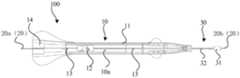
图1为一实施方式的旋磨系统的结构示意图;Fig. 1 is a schematic structural view of a rotational atherectomy system according to an embodiment;

图2为一实施方式的旋磨系统的驱动手柄的内部结构示意图;Fig. 2 is a schematic diagram of the internal structure of the driving handle of the rotational atherectomy system in one embodiment;

图3为一实施方式的旋磨系统的驱动手柄中,驱动组件移动过程中,第一伸缩导向件和第二伸缩导向件的伸缩结构示意图;3 is a schematic diagram of the telescopic structure of the first telescopic guide and the second telescopic guide during the movement of the drive assembly in the drive handle of the rotational atherectomy system according to an embodiment;

图4为一实施方式的旋磨系统的驱动手柄中,伸缩导向件的结构示意图;Fig. 4 is a structural schematic diagram of the telescopic guide in the driving handle of the rotational atherectomy system according to an embodiment;

图5为图4示出的伸缩导向结构的A部分结构的局部放大示意图;Fig. 5 is a partially enlarged schematic diagram of the structure of part A of the telescopic guide structure shown in Fig. 4;

图6为一实施方式的旋磨系统的驱动手柄的局部结构的剖面结构示意图。Fig. 6 is a schematic cross-sectional structural view of a partial structure of a driving handle of a rotational atherectomy system according to an embodiment.

附图标号说明:100、旋磨系统;10、驱动手柄;10a、导丝腔;11、手柄壳体;11a、第一壳体;11b、第二壳体;111、第一支撑部;112、第二支撑部;113、第三支撑部;114、第四支撑部;12、驱动组件;13、伸缩导向件;13A、第一伸缩导向件;13B、第二伸缩导向件;131、套管;131a、第一套管;131b、第二套管;132、滚动件;1311、第一限位部;1312、第二限位部;1313、第三限位部;133、润滑涂层;134、通液孔;14、锁丝组件;15、轨道;20、旋磨导丝;30、旋磨导管;31、旋磨头;32、传动软轴。Description of reference numerals: 100, rotary atherectomy system; 10, driving handle; 10a, guide wire chamber; 11, handle housing; 11a, first housing; 11b, second housing; 111, first support part; 112 , the second support part; 113, the third support part; 114, the fourth support part; 12, the driving assembly; 13, the telescopic guide; 13A, the first telescopic guide; 13B, the second telescopic guide; 131, the sleeve Tube; 131a, first casing; 131b, second casing; 132, rolling element; 1311, first limiting part; 1312, second limiting part; 1313, third limiting part; 133,lubricating coating 134, liquid hole; 14, locking wire assembly; 15, track; 20, rotational atherectomy guide wire; 30, rotational atherectomy catheter;

具体实施方式Detailed ways

为了便于理解本发明,下面将参照相关附图对本发明进行更全面的描述。附图中给出了本发明的首选实施例。但是,本发明可以以许多不同的形式来实现,并不限于本文所描述的实施例。相反地,提供这些实施例的目的是使对本发明的公开内容更加透彻全面。In order to facilitate the understanding of the present invention, the present invention will be described more fully below with reference to the associated drawings. A preferred embodiment of the invention is shown in the drawings. However, the present invention can be embodied in many different forms and is not limited to the embodiments described herein. Rather, these embodiments are provided so that the disclosure of the present invention will be thorough and complete.

需要说明的是,采用“近端”、“远端”作为方位词,该方位词为介入医疗器械领域惯用术语,其中“近端”表示器械作用时靠近术者的一端,“远端”表示器械作用时远离术者的一端,例如,图1示出的旋磨系统100中,驱动手柄10的左侧端部为驱动手柄10的近端,驱动手柄10的右侧端部为驱动手柄10的远端。It should be noted that "proximal end" and "distal end" are used as orientation words, which are commonly used terms in the field of interventional medical devices, where "proximal end" means the end close to the operator when the device works, and "distal end" means The end of the instrument is far away from the operator when it works. For example, in therotational atherectomy system 100 shown in FIG. the far end.

本发明的实施例中,轴向指平行于医疗器械远端中心和近端中心连线的方向;径向指垂直于上述轴向的方向。In the embodiments of the present invention, the axial direction refers to the direction parallel to the center of the distal end and the center of the proximal end of the medical device; the radial direction refers to the direction perpendicular to the aforementioned axial direction.

参阅图1和图2所示,本发明提供一种旋磨系统100,包括驱动手柄10、旋磨导丝20和旋磨导管30。旋磨导丝20和旋磨导管30的近端均与驱动手柄10相连接。旋磨导丝20作为在体内建立路径的结构件,用于引导旋磨导管30进入血管中需要进行旋磨的位置。具体地,旋磨导管30套设在旋磨导丝20上,并且能够通过操作驱动手柄10实现旋磨导管30绕旋磨导丝20转动,以及旋磨导管30沿旋磨导丝20移动,以便旋磨导管30在旋磨导丝20的引导下进行旋磨。需要说明的是,在本发明中,对于细长的结构件而沿,涉及一个结构件沿另一个结构件移动,指的是该一个结构件沿该另一个结构件的轴向移动。以旋磨导管30沿旋磨导丝20移动为例,旋磨导管30沿旋磨导丝20移动即旋磨导管30沿旋磨导丝20的轴向移动。Referring to FIGS. 1 and 2 , the present invention provides arotational atherectomy system 100 , which includes a driving handle 10 , a rotationalatherectomy guide wire 20 and arotational atherectomy catheter 30 . Both the proximal ends of theatherectomy guide wire 20 and theatherectomy catheter 30 are connected with the driving handle 10 . Theatherectomy guide wire 20 is used as a structural component for establishing a path in the body, and is used to guide theatherectomy catheter 30 into the blood vessel where the atherectomy is required. Specifically, theatherectomy catheter 30 is sleeved on theatherectomy wire 20, and theatherectomy catheter 30 can be rotated around theatherectomy guide wire 20 by operating the driving handle 10, and theatherectomy catheter 30 can move along theatherectomy guide wire 20, So that theatherectomy catheter 30 performs atherectomy under the guidance of theatherectomy wire 20 . It should be noted that, in the present invention, for an elongated structural member, it refers to the movement of one structural member along another structural member, which means that the one structural member moves along the axial direction of the other structural member. Taking theatherectomy catheter 30 moving along theatherectomy wire 20 as an example, theatherectomy catheter 30 moves along theatherectomy wire 20 , that is, theatherectomy catheter 30 moves along the axial direction of theatherectomy wire 20 .

发明人发现,旋磨导管30沿旋磨导丝20轴向移动的行程会影响旋磨效果的好坏。比如,旋磨导管30沿旋磨导丝20轴向移动的行程不够,在操作驱动手柄10来控制旋磨导管30进行旋磨作业时,旋磨导管30容易出现沿旋磨导丝20的轴向移动位移过小而无法开通病变的血管,这就需要加大操作旋磨导管30相对旋磨导丝20的轴向移动的行程。然而,在驱动手柄10配置较长的导轨来满足旋磨导管30的轴向运动行程的调整需要时,驱动手柄10的整体结构笨重,需要配置大的操作平台,操作便捷性不佳。发明人经过不断探索,对驱动手柄10的结构加以改进,在满足旋磨导管30沿旋磨导丝20在轴向上的运动行程的情形下,使得驱动手柄10轻便,易于操控旋磨导管30进行旋磨作业。The inventors found that the stroke of therotational atherectomy catheter 30 axially moving along the rotationalatherectomy guide wire 20 will affect the effect of the rotational atherectomy. For example, the axial movement of theatherectomy catheter 30 along theatherectomy wire 20 is not enough. When the drive handle 10 is operated to control theatherectomy catheter 30 to perform the atherectomy operation, theatherectomy catheter 30 is likely to appear along the axis of theatherectomy guide wire 20. If the axial displacement is too small to open the diseased blood vessel, it is necessary to increase the stroke of the axial movement of therotational atherectomy catheter 30 relative to the rotationalatherectomy guide wire 20 . However, when the driving handle 10 is configured with a longer guide rail to meet the adjustment requirements of the axial movement stroke of therotational atherectomy catheter 30 , the overall structure of the driving handle 10 is bulky, requiring a large operating platform, and the operation convenience is not good. After continuous exploration, the inventor improved the structure of the driving handle 10, and made the driving handle 10 light and easy to control therotating atherectomy catheter 30 under the condition of satisfying the movement stroke of theatherectomy guide wire 20 in the axial direction. Perform rotational grinding.

具体地,驱动手柄10包括手柄壳体11、驱动组件12和伸缩导向件13。手柄壳体11用于方便操作者握持,以进行旋磨操控。手柄壳体11具有导丝腔10a,导丝腔10a贯穿驱动手柄10的近端和驱动手柄10的远端,导丝腔10a用于供旋磨导丝20穿过。参阅图1所示,旋磨导丝20穿设于导丝腔10a,旋磨导丝20的近端20a伸出导丝腔10a的近端,旋磨导丝20的远端20b伸出导丝腔10a的远端。可理解地,旋磨导丝20可以沿导丝腔10a移动,以便将旋磨导丝20穿入血管内,并引导旋磨导管30在血管内沿轴向移动。Specifically, the driving handle 10 includes ahandle housing 11 , adriving assembly 12 and atelescopic guide 13 . Thehandle housing 11 is used for the convenience of the operator to hold, so as to perform rotational atherectomy. Thehandle housing 11 has aguide wire cavity 10a, which runs through the proximal end of the driving handle 10 and the distal end of the driving handle 10, and theguide wire cavity 10a is used for the rotationalgrinding guide wire 20 to pass through. Referring to Fig. 1, theAtherectomy guide wire 20 is installed in theguide wire cavity 10a, theproximal end 20a of theAtherectomy guide wire 20 protrudes from the proximal end of theguide wire cavity 10a, and thedistal end 20b of theAtherectomy guide wire 20 extends out of theguide wire cavity 10a. The distal end of thewire lumen 10a. Understandably, theatherectomy guide wire 20 can move along theguide wire lumen 10a, so as to penetrate theatherectomy guide wire 20 into the blood vessel, and guide theatherectomy catheter 30 to move axially in the blood vessel.

驱动组件12设置于手柄壳体11内,并用于驱使驱动轴(图未示出)绕旋磨导丝20转动。具体地,驱动轴套设于旋磨导丝20,在驱动组件12的驱使下,驱动轴绕旋磨导丝20转动并带动旋磨导管30绕旋磨导丝20转动,以实现旋磨导管30进行旋磨作业。The drivingassembly 12 is disposed in thehandle housing 11 and is used to drive a driving shaft (not shown) to rotate around therotational atherectomy wire 20 . Specifically, the drive shaft is sleeved on theAtherectomy wire 20. Driven by thedrive assembly 12, the drive shaft rotates around theAtherectomy wire 20 and drives theAtherectomy catheter 30 to rotate around theAtherectomy guide wire 20, so as to realize the rotation of theAtherectomy catheter 30. 30 for rotational atherectomy.

驱动组件12能够沿旋磨导丝20在手柄壳体11内移动,这样与驱动组件12相连接的旋磨导管30也将随着驱动组件12一起沿旋磨导丝20移动,继而旋磨导管30在对病变的血管中的动脉硬化斑块进行打磨时,旋磨导管30可以在旋转的同时,在血管中来回移动,以利于祛除钙化或纤维化的动脉硬化斑块,开通斑块堵塞的血管。Thedrive assembly 12 can move along theatherectomy wire 20 in thehandle housing 11, so that theatherectomy catheter 30 connected to thedrive assembly 12 will also move along theatherectomy guide wire 20 together with thedrive assembly 12, and then theatherectomy catheter 30 When grinding the arteriosclerotic plaque in the diseased blood vessel, therotational atherectomy catheter 30 can move back and forth in the blood vessel while rotating, so as to facilitate the removal of calcified or fibrotic arteriosclerotic plaque and open the clogged area of the plaque. Blood vessel.

伸缩导向件13沿导丝腔10a设置,伸缩导向件13与驱动组件12联动连接,当驱动组件12连同驱动轴沿旋磨导丝20移动时,伸缩导向件13于手柄壳体11内伸缩运动。伸缩导向件13在伸缩运动的过程中,能够为导丝腔10a内的例如旋磨导丝20或旋磨导管30等细长元件提供支撑。具体地,伸缩导向件13形成有引导通道,引导通道对穿设于其内的结构起到径向支撑且轴向引导的作用,其中,径向支撑指的是在径向上可以起到承托作用,从而使得穿设于引导通道内的结构不会产生大的完全,相应地,轴向引导指的是引导通道可以供穿设于其内的结构沿轴向移动,从而引导通道对穿设于其内的结构起到导向效果。Thetelescopic guide 13 is arranged along theguide wire cavity 10a, and thetelescopic guide 13 is linked with thedrive assembly 12. When thedrive assembly 12 and the drive shaft move along the grindingguide wire 20, thetelescopic guide 13 telescopically moves in thehandle housing 11 . Thetelescoping guide 13 can provide support for elongated elements such as theatherectomy guide wire 20 or theatherectomy catheter 30 in theguide wire cavity 10 a during the telescopic movement. Specifically, thetelescopic guide 13 is formed with a guide channel, which plays a role of radially supporting and axially guiding the structure passing through it, wherein the radial support means that it can support in the radial direction function, so that the structure passing through the guiding channel will not produce a large completeness. Correspondingly, the axial guiding means that the guiding channel can allow the structure passing through it to move in the axial direction, so that the guiding channel can pass through the structure. The structure within it acts as a guide.

由于在驱动组件12连同驱动轴沿旋磨导丝20移动时,伸缩导向件13可以伸缩运动并能够为穿设于引导通道的结构起到径向支撑且轴向引导的作用,从而驱动手柄10无需配置大型操作平台来维持诸如旋磨导丝20或旋磨导管30等结构的轴向移动导向。而且,由于伸缩导向件13可以伸缩运动,从而不会干涉驱动组件12沿旋磨导丝20的移动,满足驱动组件12带着旋磨导管30沿旋磨导丝20运动足够的行程的需要。基于此,伸缩导向件13的设置,有效提升驱动手柄10操作轻便性。Because when thedrive assembly 12 and the drive shaft move along theatherectomy guide wire 20, thetelescopic guide 13 can move telescopically and can play a role of radial support and axial guidance for the structure passing through the guide channel, thereby driving the handle 10 There is no need to configure a large operating platform to maintain the axial movement guidance of structures such as theatherectomy wire 20 or theatherectomy catheter 30 . Moreover, since thetelescoping guide 13 can move telescopically, it will not interfere with the movement of thedrive assembly 12 along theatherectomy wire 20 , meeting the requirement that thedrive assembly 12 can move along theatherectomy guide wire 20 with theatherectomy catheter 30 for a sufficient stroke. Based on this, the arrangement of thetelescopic guide 13 effectively improves the portability of the driving handle 10 in operation.

需要说明的是,伸缩导向件13在手柄壳体11内的设置位置不同,穿设于伸缩导向件13的引导通道的元件也不同,从而伸缩导向件13所支撑引导的对象也不同。It should be noted that the installation position of thetelescopic guide 13 in thehandle housing 11 is different, and the elements passing through the guiding channel of thetelescopic guide 13 are also different, so the objects supported and guided by thetelescopic guide 13 are also different.

下面将分别就伸缩导向件13在手柄壳体11中的结构设置对驱动手柄10的结构做进一步说明。The structure of the driving handle 10 will be further described below with respect to the structural arrangement of thetelescopic guide 13 in thehandle housing 11 .

结合图1和图2所示,驱动组件12的近端侧和驱动组件12的远端侧均设置有伸缩导向件13。为便于说明,将位于驱动组件12的远端侧的伸缩导向件13称为“第一伸缩导向件13A”,将位于驱动组件12的近端侧的伸缩导向件13称为“第二伸缩导向件13B”,相应地,将第一伸缩导向件13A形成的引导通道称为“第一引导通道”,将第二伸缩导向件13B形成的引导通道称为“第二引导通道”。结合3所示,第一伸缩导向件13A和第二伸缩导向件13B分别连接于驱动组件12的远端侧和驱动组件12的近端侧。当驱动组件12于手柄壳体11内朝远端移动时,第一伸缩导向件13A收缩,第二伸缩导向件13B伸展;当驱动组件12于手柄壳体11内朝近端移动时,第一伸缩导向件13A伸展,第二伸缩导向件13B收缩。该实施方式中,第一伸缩导向件13A的远端与手柄壳体11相连接,第一伸缩导向件13A的近端与驱动组件12相连接,旋磨导丝20及套设于旋磨导丝20的驱动轴一起穿设于第一伸缩导向件13A的第一引导通道,以利用第一伸缩导向件13A对驱动轴及位于驱动轴内的旋磨导丝20起到径向支撑且轴向引导的效果。As shown in FIG. 1 and FIG. 2 , both the proximal side of the drivingassembly 12 and the distal side of the drivingassembly 12 are provided withtelescopic guides 13 . For ease of description, thetelescopic guide 13 located at the distal end side of thedrive assembly 12 is referred to as "the firsttelescopic guide 13A", and thetelescopic guide 13 located at the proximal end of thedrive assembly 12 is referred to as "the secondtelescopic guide 13A". 13B", correspondingly, the guide channel formed by the firsttelescopic guide 13A is called "the first guide channel", and the guide channel formed by the secondtelescopic guide 13B is called "the second guide channel". As shown in connection 3, the firsttelescopic guide 13A and the secondtelescopic guide 13B are respectively connected to the distal side of the drivingassembly 12 and the proximal side of the drivingassembly 12 . When thedrive assembly 12 moves toward the distal end in thehandle housing 11, the firsttelescopic guide 13A shrinks, and the secondtelescopic guide 13B expands; when thedrive assembly 12 moves toward the proximal end in thehandle housing 11, the first Thetelescopic guide 13A expands, and the secondtelescopic guide 13B contracts. In this embodiment, the distal end of the firsttelescopic guide 13A is connected to thehandle housing 11, the proximal end of the firsttelescopic guide 13A is connected to thedrive assembly 12, and the rotational grindingguide wire 20 is sleeved on the rotational grinding guide. The drive shaft of thewire 20 is passed through the first guide channel of the firsttelescopic guide member 13A, so that the drive shaft and therotational atherectomy wire 20 located in the drive shaft can be radially supported by the firsttelescopic guide member 13A. The effect of orientation.

第二伸缩导向件13B的远端与驱动组件12相连接,第二伸缩导向件13B的近端与手柄壳体11相连接,从驱动组件12在手柄壳体11内沿轴向移动时,会带动第二伸缩导向件13B伸缩运动。驱动轴的近端与驱动组件13相连接,旋磨导丝20的近端从驱动轴的近端穿出并穿设于第二伸缩导向件13B的第二引导通道,从而利用该第二伸缩导向件13B能够对旋磨导丝20伸出驱动轴的近端的部分起到径向支撑且轴向引导的效果,从而使得旋磨导丝20不容易向偏离周向方向弯曲,确保旋磨导丝20的稳定性。The distal end of the secondtelescopic guide 13B is connected to thedrive assembly 12, and the proximal end of the secondtelescopic guide 13B is connected to thehandle housing 11. When thedrive assembly 12 moves axially in thehandle housing 11, it will Drive the telescopic movement of the secondtelescopic guide 13B. The proximal end of the drive shaft is connected to thedrive assembly 13, and the proximal end of theatherectomy guide wire 20 passes through the proximal end of the drive shaft and passes through the second guide channel of the secondtelescopic guide member 13B, thereby utilizing the second telescopic Theguide 13B can radially support and axially guide the portion of therotational atherectomy wire 20 protruding from the proximal end of the drive shaft, so that therotational atherectomy wire 20 is not easy to bend in a direction that deviates from the circumferential direction, ensuring that theatherectomy wire 20Guidewire 20 Stability.

需要说明的是,第一伸缩导向件13A和第二伸缩导向件13B并非必要同时出现,确切的说,去掉其中一个,另一个仍可以发挥相应的作用效果。例如,在一些实施方式中,驱动手柄10设置有第一伸缩导向件13A,具体地,第一伸缩导向件13A的远端与手柄壳体11相连接,第一伸缩导向件13A的近端与驱动组件12相连接,继而使得第一伸缩导向件13A与驱动组件12联动连接,以在驱动组件12相对手柄壳体11沿轴向移动时,驱动组件12能够带动第一伸缩导向件13A伸缩运动。由于驱动轴穿设于第一引导通道,从而第一伸缩导向件13A伸缩运动的过程中可以对驱动轴及位于驱动轴内的旋磨导丝20起到径向支撑且轴向引导的作用,从而使得旋磨导丝20和驱动轴维持良好的同轴性而不容易向偏离周向方向弯曲,确保旋磨操作的稳定性。需要说明的是,第一伸缩导向件13A的近端可以是与驱动组件12相连接,实现两者之间的联动连接。在一些实施方式中,第一伸缩导向件13A也可以是穿设于驱动组件12的方式实现与驱动组件12的联动连接。具体地,第一伸缩导向件13A穿设驱动组件12,使得第一伸缩导向件13A的近端从驱动组件12的近端侧伸出,从而可以利用第一伸缩导向件13A伸出驱动组件12的近端侧的部分来对旋磨导丝20的靠近驱动组件12的近端侧的部分进行支撑导向,这样,第一伸缩导向件13A不仅可以在驱动组件12的远端侧实现对驱动轴及位于驱动轴内的旋磨导丝20进行支撑,同时,还可以对位于驱动组件12的近端侧的旋磨导丝20的部分结构进行支撑,进一步使得旋磨导丝20整体稳定,以便旋磨导丝20稳定地引导旋磨导管30进行旋磨,提高旋磨稳定性。It should be noted that the firsttelescopic guide 13A and the secondtelescopic guide 13B do not necessarily appear at the same time, to be exact, if one of them is removed, the other can still play a corresponding role. For example, in some embodiments, the driving handle 10 is provided with a firsttelescopic guide 13A, specifically, the distal end of the firsttelescopic guide 13A is connected to thehandle housing 11, and the proximal end of the firsttelescopic guide 13A is connected to the Thedrive assembly 12 is connected, and then the firsttelescopic guide 13A is linked with thedrive assembly 12, so that when thedrive assembly 12 moves axially relative to thehandle housing 11, thedrive assembly 12 can drive the firsttelescopic guide 13A to move telescopically. . Since the drive shaft is passed through the first guide channel, the firsttelescopic guide member 13A can play a role in radially supporting and axially guiding the drive shaft and therotational atherectomy wire 20 inside the drive shaft during the telescopic movement. Therefore, the rotationalatherectomy guide wire 20 and the driving shaft maintain good coaxiality and are not easily bent in a direction deviated from the circumferential direction, thereby ensuring the stability of the rotational atherectomy operation. It should be noted that the proximal end of thefirst telescoping guide 13A may be connected with the drivingassembly 12 to realize the linkage connection between the two. In some implementations, thefirst telescoping guide 13A may also pass through the drivingassembly 12 to realize linkage connection with the drivingassembly 12 . Specifically, the firsttelescopic guide 13A passes through thedrive assembly 12, so that the proximal end of the firsttelescopic guide 13A protrudes from the proximal end side of thedrive assembly 12, so that the firsttelescopic guide 13A can be used to extend thedrive assembly 12 The part on the proximal side of theatherectomy guide wire 20 is used to support and guide the part near the proximal side of thedrive assembly 12. In this way, thefirst telescoping guide 13A can not only realize the alignment of the drive shaft on the distal side of thedrive assembly 12. and theatherectomy wire 20 located in the drive shaft are supported, and at the same time, the partial structure of theatherectomy guide wire 20 located on the proximal side of thedrive assembly 12 can also be supported, further making theatherectomy guide wire 20 overall stable, so that Theatherectomy guide wire 20 stably guides theatherectomy catheter 30 to perform atherectomy, improving the stability of the atherectomy.

对于驱动手柄10的手柄壳体11内设置有2个或2个以上的伸缩导向件13时,这些伸缩导向件13的结构可以相同,也可以不同。如图3所示,在一些实施方式中,第一伸缩导向件13A和第二伸缩导向件13B采取相同的结构时,第一伸缩导向件13A和第二伸缩导向件13B的尺寸不同。When two or moretelescopic guides 13 are arranged in thehandle housing 11 of the drive handle 10, the structures of thesetelescopic guides 13 can be the same or different. As shown in FIG. 3 , in some embodiments, when the firsttelescopic guide 13A and the secondtelescopic guide 13B have the same structure, the sizes of the firsttelescopic guide 13A and the secondtelescopic guide 13B are different.

下面将对伸缩导向件13的结构加以说明,第一伸缩导向件13A的结构可以是下面伸缩导向件13中的任意一种,第二伸缩导向件13B的结构也可以是下面伸缩导向件13中的任意一种。The structure of thetelescopic guide 13 will be described below. The structure of the firsttelescopic guide 13A can be any one of the following telescopic guides 13, and the structure of the secondtelescopic guide 13B can also be the one of the following telescopic guides 13. any of the

具体地,结合图3所示,伸缩导向件13包括2个或2个以上的套管131,2个或2个以上的套管131彼此套接,且能够沿轴向相对伸缩运动。Specifically, as shown in FIG. 3 , thetelescopic guide 13 includes two ormore sleeves 131 , and the two ormore sleeves 131 are socketed with each other and can move relative to each other in the axial direction.

为了更进一步理解伸缩导向件13的结构,下面将以伸缩导向件13包括第一套管131a和套设于第一套管131a的第二套管131b为例对伸缩导向件13的结构做进一步说明。In order to further understand the structure of thetelescopic guide 13, the structure of thetelescopic guide 13 will be further described by taking thetelescopic guide 13 as an example including afirst sleeve 131a and asecond sleeve 131b sleeved on thefirst sleeve 131a. illustrate.

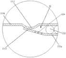
结合图4所示,在彼此套接的第一套管131a和第二套管131b之间设置有滚动件132,确切的说,第一套管131a的外壁和第二套管131b的内壁之间装载有滚动件132。当第一套管131a和第二套管131b沿轴向相对伸缩运动时,滚动件132于第一套管131a的外壁和第二套管131b的内壁之间滚动,利用滚动件132提升第一套管131a和第二套管131b彼此相对伸缩运动的顺畅性。As shown in FIG. 4 , a rollingmember 132 is provided between thefirst sleeve 131 a and thesecond sleeve 131 b that are nested in each other, to be precise, between the outer wall of thefirst sleeve 131 a and the inner wall of thesecond sleeve 131 b.Rollers 132 are mounted between them. When thefirst sleeve 131a and thesecond sleeve 131b move relatively telescopically in the axial direction, the rollingelement 132 rolls between the outer wall of thefirst sleeve 131a and the inner wall of thesecond sleeve 131b, and the rollingelement 132 is used to lift the first The smoothness of the telescopic movement of thesleeve 131a and thesecond sleeve 131b relative to each other.

需要说明的是,在伸缩导向件13包括2个或2个以上的套管131的实施方式中,任意相邻设置的2个套管131之间均设有滚动件132,当伸缩导向件13伸缩运动时,滚动件132与相应的套管131之间滚动接触,从而利用滚动件132减少套管131之间的滑动摩擦,提高套管131之间伸缩运动的顺畅性,使得伸缩导向件13整体上伸缩灵活。It should be noted that, in the embodiment where thetelescopic guide 13 includes two ormore bushings 131, a rollingmember 132 is provided between any twoadjacent bushings 131, when thetelescopic guide 13 During the telescopic movement, the rollingelement 132 is in rolling contact with thecorresponding bushing 131, so that the sliding friction between thebushings 131 is reduced by the rollingelement 132, and the smoothness of the telescopic movement between thebushings 131 is improved, so that thetelescopic guide 13 The whole is scalable and flexible.

为了提高滚动件132在伸缩导向件13伸缩运动时的运动稳定性,避免滚动件132随意乱动而影响助滑效果,在相邻的套管131之间设置有限位结构,以利用限位结构限定滚动件132的运动区域。结合图4所示,以第一套管131a与第二套管131b之间的结构为例,第二套管131b的内壁所在一侧形成有第一限位部1311和第二限位部1312,滚动件132限位于第一限位部1311和第二限位部1312之间所界定的区域Q内,从而滚动件132不会从第一套管131a和第二套管131b之间滑出。In order to improve the motion stability of the rollingelement 132 during the telescopic movement of thetelescopic guide 13 and avoid the random movement of the rollingelement 132 and affect the sliding effect, a limiting structure is provided betweenadjacent sleeves 131 to utilize the limiting structure The movement area of the rollingmember 132 is limited. As shown in FIG. 4 , taking the structure between thefirst sleeve 131a and thesecond sleeve 131b as an example, the side of the inner wall of thesecond sleeve 131b is formed with a first limitingportion 1311 and a second limitingportion 1312 , the rollingelement 132 is limited in the area Q defined between the first limitingportion 1311 and the second limitingportion 1312, so that the rollingelement 132 will not slip out from between thefirst sleeve 131a and thesecond sleeve 131b .

结合图4和图5所示,第一套管131a的一端形成有第三限位部1313,第三限位部1313用于与第一限位部1311相抵,以限制第一套管131a相对第二套管131b的极限伸缩长度。As shown in FIG. 4 and FIG. 5 , one end of thefirst sleeve 131a is formed with a third limitingportion 1313, and the third limitingportion 1313 is used to abut against the first limitingportion 1311 so as to limit the relative position of thefirst sleeve 131a. The limit stretching length of thesecond sleeve 131b.

第一限位部1311可以是环绕第二套管131b的轴向的环形凸起。例如,将第二套管131b的管壁朝内挤压,使得第二套管131b的部分管壁内凹形成环形凸起,这种结构便于加工。The first limitingportion 1311 may be an axial annular protrusion surrounding thesecond sleeve 131b. For example, the tube wall of thesecond sleeve 131b is pressed inward, so that part of the tube wall of thesecond sleeve 131b is concaved to form an annular protrusion, which is convenient for processing.

第二限位部1312的结构可以与第一限位部1311的结构相同。在一些实施方式中,第二限位部1312的结构也可以与第一限位部1311的结构不同。例如,第二限位部1312形成于第二套管131b用于供第一套管131a伸出的一端,具体地,第二限位部1312由第二套管131b对应该端部的管壁向内弯折形成。再例如,第二限位部1312与第二套管131b为分体结构,具体可以是采取呈环形的挡片与第二套管131b的端部相连,从而使得环形的挡片形成第二限位部1312。可理解地,该环形的挡片的内圈直径与第一套管131a的外径相适配,使得第一套管131a可活动地由该环形的挡片的内圈伸入第二套管131b。环形的挡片可以是通过焊接、胶水连接或螺纹连接等方式与第二套管131b相连接,在此不作限定。The structure of the second limitingportion 1312 may be the same as that of the first limitingportion 1311 . In some implementations, the structure of the second limitingportion 1312 may also be different from that of the first limitingportion 1311 . For example, the second limitingportion 1312 is formed at one end of thesecond sleeve 131b for thefirst sleeve 131a to protrude from. Specifically, the second limitingportion 1312 is formed by thesecond sleeve 131b corresponding to the tube wall of the end. Bend inwards to form. For another example, the second limitingpart 1312 and thesecond sleeve 131b are separate structures, specifically, an annular blocking piece may be adopted to connect with the end of thesecond sleeve 131b, so that the annular blocking piece forms the second limiting portion.bit part 1312. Understandably, the diameter of the inner ring of the annular blocking piece is adapted to the outer diameter of thefirst sleeve 131a, so that thefirst sleeve 131a can movably extend from the inner ring of the annular blocking piece into thesecond sleeve 131b. The ring-shaped blocking piece may be connected to thesecond sleeve 131b by means of welding, glue connection or screw connection, which is not limited herein.

第三限位部1313可以是由第一套管131a的管壁的部分结构向外扩张形成。例如,结合图4和图5所示,第一套管131a的端部的管壁向外扩张形成的第三限位部1313呈喇叭口形状,在第一套管131a于第二套管131b内轴向移动至使得第三限位部1313与第一限位部1311相接触时,第一套管131a达到从第二套管131b内伸出最大长度,第一套管131a便无法继续从第二套管131b伸展运动。在其他实施方式中,第三限位部1313可以是形成于第一套管131a的外壁的凸起,在此不作限定。The third limitingportion 1313 may be formed by expanding outwards a part of the tube wall of thefirst sleeve 131a. For example, as shown in FIG. 4 and FIG. 5 , the third limitingportion 1313 formed by the outward expansion of the tube wall at the end of thefirst sleeve 131a is in the shape of a bell mouth, and thefirst sleeve 131a and thesecond sleeve 131b When the inner axis moves until the third limitingportion 1313 contacts the first limitingportion 1311, thefirst sleeve 131a reaches the maximum length protruding from thesecond sleeve 131b, and thefirst sleeve 131a cannot continue to extend from thesecond sleeve 131b. Thesecond sleeve 131b is extended. In other embodiments, the third limitingportion 1313 may be a protrusion formed on the outer wall of thefirst sleeve 131a, which is not limited herein.

需要特别说明的是,由于滚动件132被约束在第一限位部1311和第二限位部1312之间,且第三限位部1313与第一限位部1311相抵时,又可以限制第一套管131a继续从第二套管131b伸出,从而使得第一套管131a和第二套管131b之间始终具有彼此嵌套的管段,以利于确保第一套管131a和第二套管131b的同轴性,提升第一套管131a和第二套管131b相对伸缩运动稳定性。It should be particularly noted that since the rollingelement 132 is constrained between the first limitingportion 1311 and the second limitingportion 1312, and when the third limitingportion 1313 is in contact with the first limitingportion 1311, the second limitingportion 1313 can be restricted. Thesleeve 131a continues to protrude from thesecond sleeve 131b, so that thefirst sleeve 131a and thesecond sleeve 131b always have pipe sections nested with each other, so as to ensure that thefirst sleeve 131a and thesecond sleeve 131b The coaxiality of thefirst sleeve 131b and thesecond sleeve 131b improve the relative telescopic movement stability.

在一些实施方式中,在第一套管131a和第二套管131b处于最大伸出位置时,第三限位部1313与第一限位部1311相抵接以限制第一套管131a继续从第二套管131b伸出,第一套管131a和第二套管131b之间彼此嵌套的管段的长度为2cm至5cm,比如为2cm、3cm、4cm或5cm。将第一套管131a和第二套管131b之间彼此嵌套的管段控制在长度为2cm至5cm的范围内,既可以确保第一套管131a和第二套管131b具有良好的同轴性,同时,避免彼此嵌套的管段过长,以便第一套管131a和第二套管131b之间获得尽可能长的伸缩行程。In some implementations, when thefirst sleeve 131a and thesecond sleeve 131b are at the maximum extension position, the third limitingportion 1313 abuts against the first limitingportion 1311 to limit thefirst sleeve 131a from continuing to extend from the second The twosleeves 131b extend out, and the length of the pipe section nested between thefirst sleeve 131a and thesecond sleeve 131b is 2cm to 5cm, such as 2cm, 3cm, 4cm or 5cm. Controlling the pipe section nested between thefirst sleeve 131a and thesecond sleeve 131b within a length of 2 cm to 5 cm can ensure that thefirst sleeve 131 a and thesecond sleeve 131 b have good coaxiality , and at the same time, avoid too long pipe sections nested with each other, so as to obtain as long a stretching stroke as possible between thefirst sleeve 131a and thesecond sleeve 131b.

基于第一套管131a是穿设于第二套管131b的对应第二限位部1312的位置,在不考虑结构之间的设计误差和装配误差的情形下,该彼此嵌套的管段的长度可以理解为第一限位部1311和第二限位部1312之间的距离。Based on the fact that thefirst sleeve 131a is passed through the position corresponding to thesecond stopper 1312 of thesecond sleeve 131b, without considering the design error and assembly error between the structures, the length of the pipe segments nested with each other It can be understood as the distance between the first limitingportion 1311 and the second limitingportion 1312 .

需要说明的是,第一套管131a和第二套管131b为圆柱管,但不限定内壁只能是圆柱形,例如,在一些实施方式中,第一套管131a和第二套管131b对应形成有第一抵持面和第二抵持面,第一抵持面和第二抵持面均为平行于伸缩导向件13的轴向的平面,第一抵持面和第二抵持面相互平行,滚动件132滚动抵接于第一抵持面和第二抵持面。It should be noted that thefirst sleeve 131a and thesecond sleeve 131b are cylindrical tubes, but the inner wall is not limited to be cylindrical. For example, in some embodiments, thefirst sleeve 131a and thesecond sleeve 131b correspond to Formed with a first abutting surface and a second abutting surface, the first abutting surface and the second abutting surface are parallel to the axial plane of thetelescopic guide 13, the first abutting surface and the second abutting surface Parallel to each other, the rollingelements 132 roll against the first abutting surface and the second abutting surface.

滚动件132优选为球形滚珠或者圆柱形滚珠。The rollingelement 132 is preferably a spherical ball or a cylindrical ball.

如图4所示,第一套管131a的外壁和/或第二套管131b的内壁设置有润滑涂层133,滚动件132与润滑涂层133相接触,以提高第一套管131a和第二套管131b在滚动件132的滚动支撑下的顺畅性。润滑涂层133的材质优选为聚四氟乙烯润滑脂。As shown in Figure 4, the outer wall of thefirst bushing 131a and/or the inner wall of thesecond bushing 131b are provided with alubricating coating 133, and the rollingelement 132 is in contact with the lubricatingcoating 133 to improve thefirst bushing 131a and the second bushing. The smoothness of thesecond sleeve 131b under the rolling support of the rollingelement 132. The lubricatingcoating 133 is preferably made of polytetrafluoroethylene grease.

结合图5所示,第一套管131a的管壁开设有通液孔134,通液孔134用于供液体流动至滚动件132。需要说明的是,通液孔134可以相滚动件132所在位置通入的液体可以是冷却液,也可以是润滑液。As shown in FIG. 5 , the tube wall of thefirst casing 131 a is provided with aliquid hole 134 , and theliquid hole 134 is used for the liquid to flow to the rollingmember 132 . It should be noted that the liquid through theliquid hole 134 may be cooling liquid or lubricating liquid at the position where the rollingmember 132 is located.

例如,在一些实施方式中,通液孔134可以向滚动件132所在位置通入冷却液,以对滚动件132进行冷却。进一步地,手柄壳体11在靠近近端的位置形成有储液腔,以存储冷却液。For example, in some embodiments, theliquid hole 134 may pass cooling liquid to the position of the rollingelement 132 to cool therolling element 132 . Further, a liquid storage chamber is formed near the proximal end of thehandle housing 11 to store cooling liquid.

再例如,在一些实施方式中,可以通过通液孔134向滚动件132所在位置通入润滑液,以利用润滑液的润滑作用降低运动过程中的摩擦,从而使得滚动件132能够顺滑地随伸缩导向件13的伸缩运动而滑动或滚动,减少出现卡滞现象,提高操作者的操作手感及对驱动组件12进行轴向移动的灵活性。For another example, in some embodiments, lubricating fluid can be passed through theliquid hole 134 to the position of the rollingelement 132, so that the lubricating effect of the lubricating fluid can reduce the friction during the movement, so that the rollingelement 132 can smoothly follow the The telescopic movement of thetelescopic guide 13 slides or rolls, which reduces the phenomenon of stagnation, improves the operator's operating feel and the flexibility of axially moving thedrive assembly 12 .

在一些实施方式中,手柄壳体11内设置有用于对伸缩导向件13进行支撑的支撑部。需要说明的是,支撑部可以是一个,也可以是多个,例如手柄壳体11内设置有2个或2个以上的支撑部。In some embodiments, a support portion for supporting thetelescopic guide 13 is disposed inside thehandle housing 11 . It should be noted that there may be one support part or multiple support parts, for example, two or more support parts are provided in thehandle housing 11 .

为了便于理解,下面对手柄壳体11内设置有第一伸缩导向件13A和第二伸缩导向件13B为例,对手柄壳体11的支撑部的结构设置做进一步说明。For ease of understanding, the firsttelescopic guide 13A and the secondtelescopic guide 13B disposed in thehandle housing 11 are taken as an example below to further describe the structural arrangement of the support portion of thehandle housing 11 .

结合图2所示,手柄壳体11内设置有第一支撑部111和第二支撑部112,第一支撑部111和第二支撑部112沿手柄壳体11的轴向间隔设置,并用于支撑第一伸缩导向件13A。第一伸缩导向件13A在第一支撑部111和第二支撑部112的作用下保持沿手柄壳体11的导丝腔10a设置。As shown in FIG. 2 , thehandle housing 11 is provided with afirst support portion 111 and asecond support portion 112 . Thefirst support portion 111 and thesecond support portion 112 are arranged at intervals along the axial direction of thehandle housing 11 and are used for supporting Thefirst telescoping guide 13A. The firsttelescoping guide member 13A is kept arranged along theguide wire cavity 10 a of thehandle housing 11 under the action of thefirst support portion 111 and thesecond support portion 112 .

手柄壳体11内设置有第三支撑部113和第四支撑部114,第三支撑部113和第四支撑部114沿手柄壳体11的轴向间隔设置,并用于支撑第二伸缩导向件13B。第二伸缩导向件13B在第三支撑部113和第四支撑部114的作用下保持沿手柄壳体11的导丝腔10a设置。Thehandle housing 11 is provided with athird support portion 113 and afourth support portion 114, thethird support portion 113 and thefourth support portion 114 are arranged at intervals along the axial direction of thehandle housing 11, and are used to support the secondtelescopic guide 13B . The secondtelescoping guide member 13B is kept arranged along theguide wire cavity 10a of thehandle housing 11 under the action of thethird support portion 113 and thefourth support portion 114 .

支撑部可以是作为手柄壳体11的结构的一部分,例如,支撑部为凸出于手柄壳体11的内壁的筋板,筋板上开设有用于供相应的伸缩导向件13穿过的孔,可理解的,该孔位于导丝腔10a的轴线上,从而穿设于该孔的伸缩导向件13被沿导丝腔10a定位。在一些实施方式中,伸缩导向件13穿设于孔后,利用胶水与筋板连接固定,这样筋板不仅可以对伸缩导向件13起到支撑作用,也对伸缩导向件13的与筋板相连接的位置起到限位作用,提高伸缩导向件13与筋板之间的连接稳定性,从而有利于伸缩导向件13在手柄壳体11内伸缩运动时对穿设于其内的结构进行稳定支撑导向。The support part may be a part of the structure of thehandle housing 11. For example, the support part is a rib protruding from the inner wall of thehandle housing 11, and the rib is provided with a hole for the correspondingtelescopic guide 13 to pass through. Understandably, the hole is located on the axis of theguide wire lumen 10a, so that thetelescopic guide 13 passing through the hole is positioned along theguide wire lumen 10a. In some embodiments, thetelescopic guide 13 is installed behind the hole, and is connected and fixed with the rib plate by glue, so that the rib plate can not only support thetelescopic guide 13, but also provide support for thetelescopic guide 13 and the rib plate. The position of the connection acts as a limiter, improving the connection stability between thetelescopic guide 13 and the rib plate, thereby helping thetelescopic guide 13 to stabilize the structure passing through it when thetelescopic guide 13 moves telescopically in thehandle housing 11 Support orientation.

结合图6所示,手柄壳体11包括第一壳体11a和第二壳体11b,第一壳体11a和第二壳体11b之间可以通过卡扣连接,也可以是通过螺丝或螺钉等连接件连接,利用第一壳体11a和第二壳体11b组合的方式,可以方便驱动手柄10内的如驱动组件12、伸缩导向件13组装至手柄壳体11内。As shown in FIG. 6 , thehandle housing 11 includes afirst housing 11a and asecond housing 11b, and thefirst housing 11a and thesecond housing 11b can be connected by buckles, or by screws or screws, etc. The connection of the connectors, using the combination of thefirst housing 11 a and thesecond housing 11 b , can facilitate the assembly of the drivingassembly 12 and thetelescopic guide 13 in the driving handle 10 into thehandle housing 11 .

在支撑部为凸出于手柄壳体11的内壁的筋板的实施方式中,第一壳体11a和第二壳体11b的内壁的对应位置处设置有筋板,筋板上开设有凹槽,在第一壳体11a和第二壳体11b相配合后,相对设置的筋板上的凹槽对合,以围合形成用于穿设伸缩导向件13的孔。利用这种结构设置,在安装伸缩导向件13时,可以将伸缩导向件13沿导丝腔10a先安装至第一壳体11a或第二壳体11b的凹槽中,然后将第一壳体11a和第二壳体11b扣合,便可以完成伸缩导向件13的安装。In the embodiment where the supporting portion is a rib protruding from the inner wall of thehandle housing 11, ribs are provided at corresponding positions on the inner walls of thefirst housing 11a and thesecond housing 11b, and grooves are opened on the ribs After thefirst shell 11a and thesecond shell 11b are matched, the grooves on the oppositely arranged ribs are aligned to enclose and form a hole for passing through thetelescopic guide 13 . Utilizing this structural arrangement, when installing thetelescopic guide 13, thetelescopic guide 13 can be first installed into the groove of thefirst housing 11a or thesecond housing 11b along theguide wire cavity 10a, and then thefirst housing 11a and thesecond housing 11b are snapped together to complete the installation of thetelescopic guide 13 .

在一些实施方式中,结合图2所示,驱动手柄10包括锁丝组件14,锁丝组件14设置于手柄壳体11内,且位于驱动组件12的近端侧。该实施方式中,锁丝组件14用于锁定穿设于导丝腔10a的旋磨导丝20,使得旋磨过程中,旋磨导丝20不会随旋磨导管30发生轴向移动或绕轴向转动,以便旋磨导丝20稳定地引导旋磨导管30进行旋磨,提高旋磨稳定性。锁丝组件14的结构,在此不作限定,锁丝组件14具体可以是夹子,也可以是穿设于手柄壳体11的顶丝,只要锁丝组件14能够在需要时可以将旋磨导丝20相对手柄壳体11固定即可。In some embodiments, as shown in FIG. 2 , the driving handle 10 includes alocking wire assembly 14 , and thelocking wire assembly 14 is disposed in thehandle housing 11 and located on the proximal side of the drivingassembly 12 . In this embodiment, thelocking wire assembly 14 is used to lock theatherectomy guide wire 20 passing through theguide wire cavity 10a, so that during the atherectomy process, theatherectomy guide wire 20 will not move axially or rotate around theatherectomy catheter 30. Axially rotate so that theatherectomy guide wire 20 can stably guide theatherectomy catheter 30 to perform atherectomy and improve the stability of the atherectomy. The structure of thelocking wire assembly 14 is not limited here. Specifically, thelocking wire assembly 14 can be a clip, or a top wire that passes through thehandle housing 11, as long as thelocking wire assembly 14 can rotate the atherectomy guide wire when needed. 20 is fixed relative to thehandle housing 11.

在驱动手柄10包括锁丝组件14的实施方式中,可以利用锁丝组件14对第二伸缩导向件13B的近端进行牵引。具体地,第二伸缩导向件13B的近端与锁丝组件14相连接,第二伸缩导向件13B的远端与驱动组件12相连接。从而在驱动组件12在手柄壳体11内沿轴向移动时,驱动组件12靠近或远离锁丝组件14,使得位于驱动组件12和锁丝组件14之间的第二伸缩导向件13B被拉伸或被压缩,继而实现第二伸缩导向件13B随驱动组件12的轴向移动而伸缩运动,在满足驱动组件12和旋磨导管30的轴向移动行程需要的同时,尽可能减少驱动手柄10的长度,以使得驱动手柄10可以轻便操作旋磨作业。In the embodiment in which the driving handle 10 includes alock wire assembly 14, thelock wire assembly 14 can be used to pull the proximal end of thesecond telescoping guide 13B. Specifically, the proximal end of the secondtelescopic guide 13B is connected to thelocking wire assembly 14 , and the distal end of the secondtelescopic guide 13B is connected to the drivingassembly 12 . Therefore, when the drivingassembly 12 moves axially in thehandle housing 11, the drivingassembly 12 approaches or moves away from thelocking wire assembly 14, so that the secondtelescopic guide 13B located between the drivingassembly 12 and thelocking wire assembly 14 is stretched Or be compressed, and then realize the telescopic movement of thesecond telescoping guide 13B with the axial movement of thedrive assembly 12, while meeting the needs of the axial movement stroke of thedrive assembly 12 and therotational atherectomy catheter 30, reduce the force of the drive handle 10 as much as possible. The length is such that the driving handle 10 can be easily operated for rotary atherectomy.

再次参阅图1所示,旋磨导管30包括旋磨头31、传动软轴32和鞘管(图未示出)。旋磨头31呈橄榄形,旋磨头31的远端部分可以设置用于提高摩擦的颗粒物,例如,20微米至30微米大小的钻石颗粒。这样旋磨头31在对病变的血管中的动脉硬化斑块进行打磨时,其远端部分的颗粒物也起到较好的打磨效果。Referring to FIG. 1 again, theatherectomy catheter 30 includes anatherectomy head 31 , aflexible drive shaft 32 and a sheath (not shown). Theatherectomy head 31 is olive-shaped, and the distal part of theatherectomy head 31 can be provided with particles for improving friction, for example, diamond particles with a size of 20 microns to 30 microns. In this way, when theatherectomy head 31 grinds the arteriosclerotic plaque in the diseased blood vessel, the particles at the distal end also have a better grinding effect.

旋磨头31可以由传动软轴32带动。具体地,旋磨头31与传动软轴32的远端相连接,传动软轴32的近端与驱动轴的远端相连接,以在驱动组件12驱使驱动轴转动时,驱动轴经传动软轴32带动旋磨头31旋转运动。在一些实施方式中,驱动轴的远端设置有第一咬合部(图未示出),传动软轴32的近端设有用于与第一咬合部相配合的第二咬合部(图未示出),利用第一咬合部和第二咬合部的配合实现传动软轴32与驱动轴的连接,继而驱动轴可以带动传动软轴32运动。进一步地,可以在驱动轴或者传动软轴32上套设限位套管,在将第一咬合部和第二咬合部相配合后,将限位套管沿轴向推至包覆第一咬合部和第二咬合部的位置,限制第一咬合部和第二咬合部分离,从而提高驱动轴与传动软轴32之间的连接稳定性。Theatherectomy head 31 can be driven by a transmissionflexible shaft 32 . Specifically, theatherectomy head 31 is connected to the distal end of the transmissionflexible shaft 32, and the proximal end of the transmissionflexible shaft 32 is connected to the distal end of the drive shaft, so that when thedrive assembly 12 drives the drive shaft to rotate, the drive shaft passes through the transmission flexible shaft. Theshaft 32 drives theatherectomy head 31 to rotate. In some embodiments, the distal end of the drive shaft is provided with a first occlusion (not shown in the figure), and the proximal end of the driveflexible shaft 32 is provided with a second occlusion (not shown in the figure) for matching with the first occlusion. Out), utilize the cooperation of the first occlusal part and the second occlusal part to realize the connection between the transmissionflexible shaft 32 and the drive shaft, and then the drive shaft can drive the transmissionflexible shaft 32 to move. Further, a limit sleeve can be sleeved on the drive shaft or theflexible transmission shaft 32, and after the first occlusion part and the second occlusion part are matched, the limit sleeve is pushed axially to cover the first occlusion The positions of the first and second occlusal parts limit the separation of the first and second occlusal parts, thereby improving the connection stability between the drive shaft and the transmissionflexible shaft 32 .

继续参阅图1所示,在一些实施方式中,手柄壳体11内设置有用于支撑驱动组件12的轨道15,以利于提升驱动组件12在手柄壳体11内沿轴向移动的稳定性。在调整驱动组件12在手柄壳体11内的轴向位置后,与驱动组件12通过驱动轴相连接的旋磨导管30能够在血管内移动,以便对病变的血管中的动脉硬化斑块进行打磨,最终开通血管。Continuing to refer to FIG. 1 , in some embodiments, thehandle housing 11 is provided with atrack 15 for supporting the drivingassembly 12 , so as to improve the stability of the drivingassembly 12 moving axially in thehandle housing 11 . After adjusting the axial position of thedrive assembly 12 in thehandle housing 11, theatherectomy catheter 30 connected with thedrive assembly 12 through the drive shaft can move in the blood vessel, so as to grind the atherosclerotic plaque in the diseased blood vessel , eventually opening the blood vessel.

传动软轴32为柔性管件,传动软轴32的管腔可以供旋磨导丝20穿过,从而方便利用传动软轴32将旋磨头31沿旋磨导丝20推至需要旋磨的位置。在旋磨过程中,驱动组件12在手柄壳体11内沿轴向移动时,传动软轴32可以随驱动轴沿轴向移动,以带着旋磨头31沿旋磨导丝20在病变的血管内移动(比如每次前后移动的距离控制在4cm内),以对动脉硬化斑块进行渐进式打磨。可理解的是,在旋磨过程中,旋磨头31受到动脉硬化斑块的轻微阻力时,可以通过传动软轴32朝远端推动旋磨头31,方便旋磨头31与动脉硬化斑块保持良好的接触,以确保打磨效果。当然,并不是说旋磨头31需要一直与脉硬化斑块保持接触,为了避免旋磨头31在病变的血管中的同一部位停留时间过长而损伤该局部位置的组织,最好在旋磨一定时间时,将旋磨头31朝近端回撤。例如,每次旋磨25秒,就将旋磨头31朝近端回撤,以离开脉硬化斑块。这样避免旋磨头31长时间旋磨容易发烫,且不利于旋磨过程的碎屑释放而容易造成血栓。The transmissionflexible shaft 32 is a flexible pipe, and the lumen of the transmissionflexible shaft 32 can pass through the rotationalatherectomy guide wire 20, so that it is convenient to use the transmissionflexible shaft 32 to push therotational atherectomy head 31 along the rotationalatherectomy guide wire 20 to the position requiring rotational atherectomy . During the process of rotational atherectomy, when thedrive assembly 12 moves axially in thehandle housing 11, the transmissionflexible shaft 32 can move axially with the drive shaft to bring theatherectomy head 31 along theatherectomy guide wire 20 in the lesion. Intravascular movement (for example, the distance of each forward and backward movement is controlled within 4cm), so as to gradually polish the atherosclerotic plaque. It can be understood that, during the atherectomy process, when theatherectomy head 31 is slightly resisted by the atherosclerotic plaque, theatherectomy head 31 can be pushed toward the distal end through the transmissionflexible shaft 32, so that theatherectomy head 31 can be easily separated from the arteriosclerotic plaque. Maintain good contact to ensure sanding results. Of course, it does not mean that theatherectomy head 31 needs to keep in contact with the arteriosclerotic plaque all the time. In order to prevent theatherectomy head 31 from staying in the same part of the diseased blood vessel for too long and damaging the tissue at this local position, it is best to use the atherectomy head After a certain period of time, theatherectomy head 31 is withdrawn toward the proximal end. For example, every time the atherectomy is performed for 25 seconds, theatherectomy head 31 is retracted proximally to leave the atherosclerotic plaque. This prevents theatherectomy head 31 from becoming hot for a long time, and is not conducive to the release of debris during the atherectomy process, which may easily cause thrombus.

鞘管可以是采取聚四氟乙烯材料制成。鞘管套设在传动软轴32的外侧,以此避免旋磨过程中,传动软轴32对血管壁造成损伤,继而鞘管可以起到保护血管壁的作用。此外,在旋磨过程中,还可以通过鞘管向旋磨位置处注入清洗液,以减小摩擦损伤和热损伤,并且可以利用清洗液及时将旋磨过程中掉落的颗粒冲掉,避免造成血流栓塞。清洗液可以是生理盐水。The sheath can be made of polytetrafluoroethylene. The sheath is sheathed on the outside of the transmissionflexible shaft 32, so as to prevent the transmissionflexible shaft 32 from causing damage to the blood vessel wall during the rotational grinding process, and then the sheath can protect the blood vessel wall. In addition, during the rotational atherectomy process, cleaning fluid can be injected into the rotational atherectomy position through the sheath to reduce frictional damage and thermal damage, and the cleaning fluid can be used to wash away the particles falling during the rotational atherectomy process in time to avoid cause blood clots. The cleaning fluid can be physiological saline.

在一些实施方式中,旋磨导丝20可以采取不锈钢材料制成。旋磨导丝20的直径和长度不作限定,只要能够适用旋磨手术需要即可。例如,旋磨导丝20的长度为300cm。对于旋磨导丝20的材质和规格,在此不作限定。In some embodiments, theatherectomy wire 20 can be made of stainless steel. The diameter and length of theatherectomy guide wire 20 are not limited, as long as it can meet the requirements of atherectomy. For example, the length of theatherectomy wire 20 is 300 cm. The material and specifications of theatherectomy wire 20 are not limited here.

以上所述实施例的各技术特征可以进行任意的组合,为使描述简洁,未对上述实施例中的各个技术特征所有可能的组合都进行描述,然而,只要这些技术特征的组合不存在矛盾,都应当认为是本说明书记载的范围。The technical features of the above-mentioned embodiments can be combined arbitrarily. To make the description concise, all possible combinations of the technical features in the above-mentioned embodiments are not described. However, as long as there is no contradiction in the combination of these technical features, should be considered as within the scope of this specification.

以上所述实施例仅表达了本发明的几种实施方式,其描述较为具体和详细,但并不能因此而理解为对申请专利范围的限制。应当指出的是,对于本领域的普通技术人员来说,在不脱离本发明构思的前提下,还可以做出若干变形和改进,这些都属于本发明的保护范围。因此,本发明专利的保护范围应以所附权利要求为准。The above-mentioned embodiments only express several implementation modes of the present invention, and the description thereof is relatively specific and detailed, but should not be construed as limiting the scope of the patent application. It should be noted that, for those skilled in the art, several modifications and improvements can be made without departing from the concept of the present invention, and these all belong to the protection scope of the present invention. Therefore, the protection scope of the patent for the present invention should be based on the appended claims.

Claims (13)

CN202111510802.3A2021-12-102021-12-10Rotary grinding system and driving handle thereofPendingCN116250900A (en)

Priority Applications (1)

Application NumberPriority DateFiling DateTitle
CN202111510802.3ACN116250900A (en)2021-12-102021-12-10Rotary grinding system and driving handle thereof

Applications Claiming Priority (1)

Application NumberPriority DateFiling DateTitle
CN202111510802.3ACN116250900A (en)2021-12-102021-12-10Rotary grinding system and driving handle thereof

Publications (1)

Publication NumberPublication Date
CN116250900Atrue CN116250900A (en)2023-06-13

Family

ID=86681415

Family Applications (1)

Application NumberTitlePriority DateFiling Date
CN202111510802.3APendingCN116250900A (en)2021-12-102021-12-10Rotary grinding system and driving handle thereof

Country Status (1)

CountryLink
CN (1)CN116250900A (en)

Citations (10)

* Cited by examiner, † Cited by third party
Publication numberPriority datePublication dateAssigneeTitle
CN1413124A (en)*1999-12-242003-04-23东丽株式会社Catheter with balloon
US20050004553A1 (en)*2003-07-022005-01-06Medtronic Ave, Inc.Sheath catheter having variable over-the-wire length and methods of use
US20120059448A1 (en)*2009-04-152012-03-08Parker Fred TEverting deployment system and handle
CN103402576A (en)*2011-01-102013-11-20聚光灯技术合伙有限责任公司Apparatus and methods for accessing and treating a body cavity, lumen, or ostium
CN108495582A (en)*2015-09-032018-09-04海王星医疗公司 An instrument used to advance an endoscope through the small intestine
US20200163693A1 (en)*2017-05-312020-05-28Terumo Kabushiki KaishaMedical device and method
WO2020208961A1 (en)*2019-04-122020-10-15株式会社東海メディカルプロダクツBalloon catheter
CN111803781A (en)*2020-07-272020-10-23厦门鑫康顺医疗科技有限公司 A retractable crawling catheter
CN214260326U (en)*2020-12-012021-09-24上海凯利泰医疗科技股份有限公司Balloon catheter with adjustable spacing
CN216985066U (en)*2021-12-102022-07-19上海鸿脉医疗科技有限公司Rotary grinding system and driving handle thereof

Patent Citations (10)

* Cited by examiner, † Cited by third party
Publication numberPriority datePublication dateAssigneeTitle
CN1413124A (en)*1999-12-242003-04-23东丽株式会社Catheter with balloon
US20050004553A1 (en)*2003-07-022005-01-06Medtronic Ave, Inc.Sheath catheter having variable over-the-wire length and methods of use
US20120059448A1 (en)*2009-04-152012-03-08Parker Fred TEverting deployment system and handle
CN103402576A (en)*2011-01-102013-11-20聚光灯技术合伙有限责任公司Apparatus and methods for accessing and treating a body cavity, lumen, or ostium
CN108495582A (en)*2015-09-032018-09-04海王星医疗公司 An instrument used to advance an endoscope through the small intestine
US20200163693A1 (en)*2017-05-312020-05-28Terumo Kabushiki KaishaMedical device and method
WO2020208961A1 (en)*2019-04-122020-10-15株式会社東海メディカルプロダクツBalloon catheter
CN111803781A (en)*2020-07-272020-10-23厦门鑫康顺医疗科技有限公司 A retractable crawling catheter
CN214260326U (en)*2020-12-012021-09-24上海凯利泰医疗科技股份有限公司Balloon catheter with adjustable spacing
CN216985066U (en)*2021-12-102022-07-19上海鸿脉医疗科技有限公司Rotary grinding system and driving handle thereof

Similar Documents

PublicationPublication DateTitle
US10123817B2 (en)Rotational atherectomy device with a system of eccentric abrading heads
CN110621243B (en)Tissue removal catheter with guidewire isolation bushing
JP5420645B2 (en) Polishing nose cone with expandable cutting and polishing area for rotary atherectomy device
US7485127B2 (en)Tubular torque transmitting system for medical device
JP6342473B2 (en) Apparatus, system and method for guiding tip bushings for rotary atherectomy
JP5285768B2 (en) Bidirectional expandable head for rotary atherectomy device
CN102438535B (en) Rotational atherectomy device and method for improving grinding efficiency
US4857046A (en)Drive catheter having helical pump drive shaft
CN103252011A (en) Material removal device and method of use
CN104968285A (en)Expandable atherectomy device
JP2010532233A (en) Cleaning apparatus and method for high speed rotary atherectomy device
CN110612065B (en)Medical device and method
US10357275B2 (en)Dual-basket self-centering rotational device for treatment of arterial occlusive disease with infinitely adjustable cutting size
US20150080795A1 (en)Devices, systems and methods for performing atherectomy and subsequent balloon angioplasty without exchanging devices
CN216985066U (en)Rotary grinding system and driving handle thereof
US20250261964A1 (en)Rotational atherectomy apparatus and rotational atherectomy device
US20140316449A1 (en)Devices, systems and methods for a quick load guide wire tool
US20180110539A1 (en)Devices, systems and methods for a piloting tip bushing for rotational atherectomy
US20140316450A1 (en)Devices, systems and methods for an oscillating crown drive for rotational atherectomy
CN217162228U (en)Rotary grinding system and rotary grinding control handle thereof
CN116250900A (en)Rotary grinding system and driving handle thereof
US10524827B2 (en)Tissue-removing catheter with ball and socket deployment mechanism
CN113995470A (en)Medical interventional aspiration catheter
CN116250899A (en)Rotary grinding system and rotary grinding control handle thereof
CN115054326A (en)Rotary grinding system, rotary grinding assembly and rotary grinding head thereof

Legal Events

DateCodeTitleDescription
PB01Publication
PB01Publication
SE01Entry into force of request for substantive examination

[8]ページ先頭

©2009-2025 Movatter.jp