CN116243815A - Touch panel, display module, display device and touch detection method - Google Patents
Touch panel, display module, display device and touch detection methodDownload PDFInfo
- Publication number
- CN116243815A CN116243815ACN202310518763.4ACN202310518763ACN116243815ACN 116243815 ACN116243815 ACN 116243815ACN 202310518763 ACN202310518763 ACN 202310518763ACN 116243815 ACN116243815 ACN 116243815A
- Authority
- CN
- China
- Prior art keywords
- touch
- point
- pressure
- points
- sensing
- Prior art date
- Legal status (The legal status is an assumption and is not a legal conclusion. Google has not performed a legal analysis and makes no representation as to the accuracy of the status listed.)
- Granted
Links
Images


Classifications
- G—PHYSICS
- G06—COMPUTING OR CALCULATING; COUNTING
- G06F—ELECTRIC DIGITAL DATA PROCESSING
- G06F3/00—Input arrangements for transferring data to be processed into a form capable of being handled by the computer; Output arrangements for transferring data from processing unit to output unit, e.g. interface arrangements
- G06F3/01—Input arrangements or combined input and output arrangements for interaction between user and computer
- G06F3/03—Arrangements for converting the position or the displacement of a member into a coded form
- G06F3/041—Digitisers, e.g. for touch screens or touch pads, characterised by the transducing means
- G06F3/0416—Control or interface arrangements specially adapted for digitisers
- G06F3/04166—Details of scanning methods, e.g. sampling time, grouping of sub areas or time sharing with display driving
- G06F3/041662—Details of scanning methods, e.g. sampling time, grouping of sub areas or time sharing with display driving using alternate mutual and self-capacitive scanning
- G—PHYSICS
- G06—COMPUTING OR CALCULATING; COUNTING
- G06F—ELECTRIC DIGITAL DATA PROCESSING
- G06F3/00—Input arrangements for transferring data to be processed into a form capable of being handled by the computer; Output arrangements for transferring data from processing unit to output unit, e.g. interface arrangements
- G06F3/01—Input arrangements or combined input and output arrangements for interaction between user and computer
- G06F3/03—Arrangements for converting the position or the displacement of a member into a coded form
- G06F3/041—Digitisers, e.g. for touch screens or touch pads, characterised by the transducing means
- G06F3/044—Digitisers, e.g. for touch screens or touch pads, characterised by the transducing means by capacitive means
- G06F3/0443—Digitisers, e.g. for touch screens or touch pads, characterised by the transducing means by capacitive means using a single layer of sensing electrodes
- G—PHYSICS
- G02—OPTICS
- G02F—OPTICAL DEVICES OR ARRANGEMENTS FOR THE CONTROL OF LIGHT BY MODIFICATION OF THE OPTICAL PROPERTIES OF THE MEDIA OF THE ELEMENTS INVOLVED THEREIN; NON-LINEAR OPTICS; FREQUENCY-CHANGING OF LIGHT; OPTICAL LOGIC ELEMENTS; OPTICAL ANALOGUE/DIGITAL CONVERTERS
- G02F1/00—Devices or arrangements for the control of the intensity, colour, phase, polarisation or direction of light arriving from an independent light source, e.g. switching, gating or modulating; Non-linear optics
- G02F1/01—Devices or arrangements for the control of the intensity, colour, phase, polarisation or direction of light arriving from an independent light source, e.g. switching, gating or modulating; Non-linear optics for the control of the intensity, phase, polarisation or colour
- G02F1/13—Devices or arrangements for the control of the intensity, colour, phase, polarisation or direction of light arriving from an independent light source, e.g. switching, gating or modulating; Non-linear optics for the control of the intensity, phase, polarisation or colour based on liquid crystals, e.g. single liquid crystal display cells
- G02F1/133—Constructional arrangements; Operation of liquid crystal cells; Circuit arrangements
- G02F1/1333—Constructional arrangements; Manufacturing methods
- G02F1/13338—Input devices, e.g. touch panels
- G—PHYSICS
- G06—COMPUTING OR CALCULATING; COUNTING
- G06F—ELECTRIC DIGITAL DATA PROCESSING
- G06F3/00—Input arrangements for transferring data to be processed into a form capable of being handled by the computer; Output arrangements for transferring data from processing unit to output unit, e.g. interface arrangements
- G06F3/01—Input arrangements or combined input and output arrangements for interaction between user and computer
- G06F3/03—Arrangements for converting the position or the displacement of a member into a coded form
- G06F3/041—Digitisers, e.g. for touch screens or touch pads, characterised by the transducing means
- G06F3/0412—Digitisers structurally integrated in a display
- G—PHYSICS
- G06—COMPUTING OR CALCULATING; COUNTING
- G06F—ELECTRIC DIGITAL DATA PROCESSING
- G06F3/00—Input arrangements for transferring data to be processed into a form capable of being handled by the computer; Output arrangements for transferring data from processing unit to output unit, e.g. interface arrangements
- G06F3/01—Input arrangements or combined input and output arrangements for interaction between user and computer
- G06F3/03—Arrangements for converting the position or the displacement of a member into a coded form
- G06F3/041—Digitisers, e.g. for touch screens or touch pads, characterised by the transducing means
- G06F3/0414—Digitisers, e.g. for touch screens or touch pads, characterised by the transducing means using force sensing means to determine a position
- G06F3/04144—Digitisers, e.g. for touch screens or touch pads, characterised by the transducing means using force sensing means to determine a position using an array of force sensing means
- G—PHYSICS
- G06—COMPUTING OR CALCULATING; COUNTING
- G06F—ELECTRIC DIGITAL DATA PROCESSING
- G06F3/00—Input arrangements for transferring data to be processed into a form capable of being handled by the computer; Output arrangements for transferring data from processing unit to output unit, e.g. interface arrangements
- G06F3/01—Input arrangements or combined input and output arrangements for interaction between user and computer
- G06F3/03—Arrangements for converting the position or the displacement of a member into a coded form
- G06F3/041—Digitisers, e.g. for touch screens or touch pads, characterised by the transducing means
- G06F3/044—Digitisers, e.g. for touch screens or touch pads, characterised by the transducing means by capacitive means
- G06F3/0445—Digitisers, e.g. for touch screens or touch pads, characterised by the transducing means by capacitive means using two or more layers of sensing electrodes, e.g. using two layers of electrodes separated by a dielectric layer
Landscapes
- Engineering & Computer Science (AREA)
- General Engineering & Computer Science (AREA)
- Theoretical Computer Science (AREA)
- Physics & Mathematics (AREA)
- General Physics & Mathematics (AREA)
- Human Computer Interaction (AREA)
- Nonlinear Science (AREA)
- Mathematical Physics (AREA)
- Chemical & Material Sciences (AREA)
- Crystallography & Structural Chemistry (AREA)
- Optics & Photonics (AREA)
- Position Input By Displaying (AREA)
Abstract
Translated fromChinese
Description
Translated fromChinese技术领域technical field
本申请涉及显示技术领域,尤其涉及一种触控面板、一种具有该触控面板的显示模组、一种具有该显示模组的显示装置以及一种触控侦测方法。The present application relates to the field of display technology, and in particular to a touch panel, a display module with the touch panel, a display device with the display module, and a touch detection method.
背景技术Background technique
触控技术使人们可以更简单、更便捷地操作电子设备以及更好地实现人机交互。随着触控行业的发展,智能手机、平板电脑以及智能手表等电子设备几乎都是采用具有触控功能的显示面板。目前,电容式触控面板因其具有较好的透光率和清晰度在日常生活中最为常见,其中,自电容式触控面板在电子设备上应用尤为普遍。Touch technology makes it easier and more convenient for people to operate electronic devices and better realize human-computer interaction. With the development of the touch industry, almost all electronic devices such as smartphones, tablet computers, and smart watches use display panels with touch functions. At present, capacitive touch panels are most commonly used in daily life because of their better light transmittance and clarity, and self-capacitive touch panels are particularly commonly used in electronic devices.
自电容式触控面板上对应有多个触控点,每个触控点对应一个横坐标和纵坐标。然而,在实际应用中,在对触控面板进行多点触控时,触控面板无法准确地同时识别多个触摸点,进而导致触摸点的坐标会出现一定的混乱而形成“鬼点”现象,“鬼点”的存在会严重地影响和干扰触控面板对触摸位置的侦测,从而造成误判实际触摸位置,降低了触控效果以及用户的使用体验。There are multiple touch points corresponding to the self-capacitive touch panel, and each touch point corresponds to an abscissa and a ordinate. However, in practical applications, when the touch panel is multi-touched, the touch panel cannot accurately identify multiple touch points at the same time, which will cause some confusion in the coordinates of the touch points and form a "ghost point" phenomenon Therefore, the existence of "ghost points" will seriously affect and interfere with the touch panel's detection of the touch position, thereby causing misjudgment of the actual touch position, reducing the touch effect and user experience.
鉴于此,如何解决现有技术中多点触摸自电容式触控面板时触摸点的坐标混乱导致的“鬼点”现象是本领域技术人员亟需解决的问题。In view of this, how to solve the "ghost point" phenomenon caused by the confusion of the coordinates of the touch points when multi-touching the self-capacitive touch panel in the prior art is an urgent problem to be solved by those skilled in the art.
发明内容Contents of the invention
鉴于上述现有技术的不足,本申请的目的在于提供一种触控面板、一种具有该触控面板的显示模组、一种具有该显示模组的显示装置以及一种触控侦测方法,其旨在解决现有技术中多点触摸自电容式触控面板时触摸点的坐标混乱导致的“鬼点”现象的问题。In view of the deficiencies in the prior art above, the purpose of this application is to provide a touch panel, a display module with the touch panel, a display device with the display module, and a touch detection method , which aims to solve the problem of the "ghost point" phenomenon caused by the confusion of the coordinates of the touch points when multi-touching the self-capacitive touch panel in the prior art.
为解决上述技术问题,本申请提供一种触控面板,所述触控电极层包括多个触控区域,所述触控面板还包括压力感应层,所述压力感应层包括多个感应组件,多个所述感应组件的位置分别与多个所述触控区域的位置相对应,所述触控电极层用于感应多个触摸点,其中,多个所述触摸点包括至少两个实际触摸点,多个所述感应组件用于感应压力点,以根据所述压力点确定所述实际触摸点所在的所述触控区域。In order to solve the above technical problems, the present application provides a touch panel, the touch electrode layer includes a plurality of touch areas, the touch panel further includes a pressure sensing layer, the pressure sensing layer includes a plurality of sensing components, The positions of the plurality of sensing components correspond to the positions of the plurality of touch areas respectively, and the touch electrode layer is used to sense a plurality of touch points, wherein the plurality of touch points include at least two actual touch points Points, the multiple sensing components are used to sense pressure points, so as to determine the touch area where the actual touch point is located according to the pressure points.
综上所述,本申请实施例公开的触控面板包括触控电极层与压力感应层,所述触控电极层包括多个触控区域,所述压力感应层包括多个感应组件。所述触控电极层用于感应多个触摸点,其中,多个所述触摸点包括至少两个实际触摸点,多个所述感应组件用于感应压力点,以根据所述压力点确定所述实际触摸点所在的所述触控区域,从而判断出触摸点是实际触摸点还是鬼点,避免了触控面板感应到鬼点,提升了触控效果以及用户的使用体验。In summary, the touch panel disclosed in the embodiment of the present application includes a touch electrode layer and a pressure sensing layer, the touch electrode layer includes a plurality of touch areas, and the pressure sensing layer includes a plurality of sensing components. The touch electrode layer is used for sensing a plurality of touch points, wherein the plurality of touch points include at least two actual touch points, and the plurality of sensing components are used for sensing pressure points, so as to determine the corresponding touch points according to the pressure points. The touch area where the actual touch point is located, thereby judging whether the touch point is an actual touch point or a ghost point, avoids the touch panel from sensing the ghost point, and improves the touch effect and user experience.
在示例性实施方式中,每个所述感应组件包括柔性元件与导电元件,所述导电元件连接于所述柔性元件的一侧,且所述柔性元件与所述导电元件之间导通,所述柔性元件在触摸时发生形变,所述柔性元件与所述导电元件之间的接触面积增大,使所述感应组件的阻值减小。In an exemplary embodiment, each of the induction components includes a flexible element and a conductive element, the conductive element is connected to one side of the flexible element, and the flexible element is connected to the conductive element, so The flexible element deforms when touched, and the contact area between the flexible element and the conductive element increases, so that the resistance value of the sensing component decreases.
在示例性实施方式中,所述柔性元件的材料包括聚二甲基硅氧烷,所述导电元件的材料包括聚苯胺。In an exemplary embodiment, the material of the flexible element includes polydimethylsiloxane, and the material of the conductive element includes polyaniline.
在示例性实施方式中,所述柔性元件包括基底与多个凸起结构,所述基底与所述导电元件相对且间隔设置,多个所述凸起结构连接于所述基底面对所述导电元件的一侧,并与所述导电元件接触,所述基底在触摸时发生形变,使多个所述凸起结构朝向所述导电元件移动,多个所述凸起结构发生形变,使多个所述凸起结构与所述导电元件的接触面积增大。In an exemplary embodiment, the flexible element includes a base and a plurality of protruding structures, the base is opposite to the conductive element and arranged at intervals, and the plurality of protruding structures are connected to the base facing the conductive element. One side of the element, and in contact with the conductive element, the substrate deforms when touched, so that a plurality of the raised structures move toward the conductive element, and the plurality of raised structures are deformed, causing a plurality of The contact area between the protruding structure and the conductive element increases.
在示例性实施方式中,在所述基底指向所述导电元件的方向上,所述凸起结构横截面的面积减小。In an exemplary embodiment, an area of a cross-section of the protrusion structure decreases in a direction in which the base points to the conductive element.
在示例性实施方式中,每个所述触控区域包括多个触控点,所述触控面板还包括坐标侦测单元,所述坐标侦测单元与所述触控电极层电连接,所述坐标侦测单元用于侦测每个所述触控点的电容以获取所述触摸点的坐标。所述触控面板还包括压力侦测单元,所述压力侦测单元分别与所述压力感应层的每个所述感应组件电连接,所述压力侦测单元用于侦测每个所述感应组件的电流以获取所述压力点的坐标。In an exemplary embodiment, each of the touch areas includes a plurality of touch points, and the touch panel further includes a coordinate detection unit, and the coordinate detection unit is electrically connected to the touch electrode layer, so The coordinate detection unit is used for detecting the capacitance of each touch point to obtain the coordinates of the touch point. The touch panel also includes a pressure detection unit, the pressure detection unit is electrically connected to each of the sensing components of the pressure sensing layer, and the pressure detection unit is used to detect each of the sensing components. component current to obtain the coordinates of the pressure point.
在示例性实施方式中,所述触控面板还包括对比单元,所述对比单元分别与所述坐标侦测单元以及所述压力侦测单元电连接,所述坐标侦测单元输出所述触摸点的坐标信号至所述对比单元,所述压力侦测单元输出所述压力点的坐标信号至所述对比单元,所述对比单元根据所述触摸点的坐标信号与所述压力点的坐标信号判断所述触摸点是否有相对应的所述压力点。In an exemplary embodiment, the touch panel further includes a comparison unit, the comparison unit is electrically connected to the coordinate detection unit and the pressure detection unit, and the coordinate detection unit outputs the touch point The coordinate signal of the touch point is sent to the comparison unit, and the pressure detection unit outputs the coordinate signal of the pressure point to the comparison unit, and the comparison unit judges according to the coordinate signal of the touch point and the coordinate signal of the pressure point Whether the touch point has a corresponding pressure point.
基于同样的发明构思,本申请还提供一种显示模组,所述显示模组包括显示面板以及上述的触控面板,所述触控面板设置于所述显示面板的出光侧。Based on the same inventive concept, the present application further provides a display module, the display module includes a display panel and the above-mentioned touch panel, and the touch panel is arranged on the light-emitting side of the display panel.
综上所述,本申请实施例提供的显示模组包括显示面板与触控面板,所述触控面板包括触控电极层与压力感应层,所述触控电极层包括多个触控区域,所述压力感应层包括多个感应组件。所述触控电极层用于感应多个触摸点,其中,多个所述触摸点包括至少两个实际触摸点,多个所述感应组件用于感应压力点,以根据所述压力点确定所述实际触摸点所在的所述触控区域,从而判断出触摸点是实际触摸点还是鬼点,避免了触控面板感应到鬼点,提升了触控效果以及用户的使用体验。To sum up, the display module provided by the embodiment of the present application includes a display panel and a touch panel, the touch panel includes a touch electrode layer and a pressure sensing layer, the touch electrode layer includes a plurality of touch areas, The pressure sensing layer includes a plurality of sensing components. The touch electrode layer is used for sensing a plurality of touch points, wherein the plurality of touch points include at least two actual touch points, and the plurality of sensing components are used for sensing pressure points, so as to determine the corresponding touch points according to the pressure points. The touch area where the actual touch point is located, thereby judging whether the touch point is an actual touch point or a ghost point, avoids the touch panel from sensing the ghost point, and improves the touch effect and user experience.
基于同样的发明构思,本申请还提供一种显示装置,所述显示装置包括驱动模块以及上述的显示模组,所述驱动模块与所述显示模组电连接,所述驱动模块用于向所述显示模组传输控制信号。Based on the same inventive concept, the present application also provides a display device, the display device includes a driving module and the above-mentioned display module, the driving module is electrically connected to the display module, and the driving module is used to provide The display module transmits control signals.
综上所述,本申请实施例提供的显示装置包括驱动模块与显示模组,所述显示模组包括显示面板与触控面板,所述触控面板包括触控电极层与压力感应层,所述触控电极层包括多个触控区域,所述压力感应层包括多个感应组件。所述触控电极层用于感应多个触摸点,其中,多个所述触摸点包括至少两个实际触摸点,多个所述感应组件用于感应压力点,以根据所述压力点确定所述实际触摸点所在的所述触控区域,从而判断出触摸点是实际触摸点还是鬼点,避免了触控面板感应到鬼点,提升了触控效果以及用户的使用体验。To sum up, the display device provided by the embodiment of the present application includes a driving module and a display module, the display module includes a display panel and a touch panel, and the touch panel includes a touch electrode layer and a pressure sensing layer. The touch electrode layer includes a plurality of touch areas, and the pressure sensing layer includes a plurality of sensing components. The touch electrode layer is used for sensing a plurality of touch points, wherein the plurality of touch points include at least two actual touch points, and the plurality of sensing components are used for sensing pressure points, so as to determine the corresponding touch points according to the pressure points. The touch area where the actual touch point is located, thereby judging whether the touch point is an actual touch point or a ghost point, avoids the touch panel from sensing the ghost point, and improves the touch effect and user experience.
基于同样的发明构思,本申请还提供一种触控侦测方法,所述触控侦测方法由上述的触控面板执行,所述触控侦测方法包括:Based on the same inventive concept, the present application also provides a touch detection method, the touch detection method is executed by the above-mentioned touch panel, and the touch detection method includes:
提供一触控面板,所述触控面板包括具有多个触控区域的触控电极层以及具有多个感应组件的压力感应层,每个所述触控区域内具有多个触控点,多个所述触控区域的位置与多个所述感应组件的位置相对应;Provide a touch panel, the touch panel includes a touch electrode layer with a plurality of touch areas and a pressure sensing layer with a plurality of sensing elements, each of the touch areas has a plurality of touch points, more The position of each touch area corresponds to the position of multiple sensing components;
侦测所述触控电极层的每个所述触控点的电容以获取多个触摸点的坐标,侦测每个所述感应组件的电流以获取压力点的坐标,其中,所述触摸点包括多个实际触摸点与多个鬼点;Detecting the capacitance of each touch point of the touch electrode layer to obtain the coordinates of multiple touch points, detecting the current of each of the sensing components to obtain the coordinates of the pressure point, wherein the touch point Including multiple actual touch points and multiple ghost points;
判断所述触摸点是否有相对应的所述压力点,其中,若所述触摸点有相对应的所述压力点,则所述触摸点为所述实际触摸点;若所述触摸点没有相对应的所述压力点,则所述触摸点为所述鬼点。Judging whether the touch point has a corresponding pressure point, wherein, if the touch point has a corresponding pressure point, the touch point is the actual touch point; if the touch point has no corresponding Corresponding to the pressure point, the touch point is the ghost point.
综上所述,本申请实施例提供的触控侦测方法通过侦测所述触控电极层的每个所述触控点的电容以获取多个触摸点的坐标与侦测每个所述感应组件的电流以获取压力点的坐标,并判断所述触摸点是否有相对应的所述压力点,来确定所述触摸点是实际触摸点还是鬼点,避免了触控面板感应到鬼点,提升了触控效果以及用户的使用体验。To sum up, the touch detection method provided by the embodiment of the present application obtains the coordinates of multiple touch points by detecting the capacitance of each touch point of the touch electrode layer and detects the capacitance of each of the touch points. Sensing the current of the component to obtain the coordinates of the pressure point, and judging whether the touch point has a corresponding pressure point, to determine whether the touch point is an actual touch point or a ghost point, avoiding the touch panel from sensing ghost points , improving the touch effect and user experience.
附图说明Description of drawings
为了更清楚地说明本申请实施例中的技术方案,下面将对实施例中所需要使用的附图作简单地介绍,显而易见地,下面描述中的附图是本申请的一些实施例,对于本领域普通技术人员来讲,在不付出创造性劳动的前提下,还可以根据这些附图获得其他的附图。In order to more clearly illustrate the technical solutions in the embodiments of the present application, the drawings that need to be used in the embodiments will be briefly introduced below. Obviously, the drawings in the following description are some embodiments of the present application. Those of ordinary skill in the art can also obtain other drawings based on these drawings without any creative effort.
图1为本申请实施例公开的触控面板的层结构示意图;FIG. 1 is a schematic diagram of the layer structure of the touch panel disclosed in the embodiment of the present application;
图2为图1所示的触控面板的触控电极层的俯视结构示意图;FIG. 2 is a schematic top view of a touch electrode layer of the touch panel shown in FIG. 1;
图3为图2所示的触控面板的触控区域的结构示意图;FIG. 3 is a schematic structural diagram of a touch area of the touch panel shown in FIG. 2;
图4为图1所示的触控面板的压力感应层的俯视结构示意图;FIG. 4 is a schematic top view of the pressure sensing layer of the touch panel shown in FIG. 1;
图5为本申请实施例公开的感应组件处于未受压状态的结构示意图;Fig. 5 is a schematic structural diagram of the sensing component disclosed in the embodiment of the present application in an unpressurized state;
图6为本申请实施例公开的感应组件处于受压状态的结构示意图;Fig. 6 is a schematic structural diagram of the sensing component disclosed in the embodiment of the present application under pressure;
图7为本申请实施例公开的坐标侦测单元与触控电极层的结构示意图;7 is a schematic structural diagram of a coordinate detection unit and a touch electrode layer disclosed in an embodiment of the present application;
图8为本申请实施例公开的压力侦测单元与压力感应层的结构示意图;FIG. 8 is a schematic structural diagram of a pressure detection unit and a pressure sensing layer disclosed in an embodiment of the present application;
图9为本申请实施例公开的显示模组的层结构示意图;FIG. 9 is a schematic diagram of the layer structure of the display module disclosed in the embodiment of the present application;
图10为本申请实施例公开的显示装置的结构示意图;FIG. 10 is a schematic structural diagram of a display device disclosed in an embodiment of the present application;
图11为本申请实施例公开的触控侦测方法的流程示意图。FIG. 11 is a schematic flowchart of a touch detection method disclosed in an embodiment of the present application.
附图标记说明:Explanation of reference signs:
1-触控面板;10-触控电极层;10a-触控区域;11-触控点;20-压力感应层;21-感应组件;40-坐标侦测单元;50-压力侦测单元;210-柔性元件;211-基底;212-凸起结构;220-导电元件;300-显示面板;400-显示模组;500-驱动模块;600-显示装置;S10-S30-触控侦测方法的步骤。1-touch panel; 10-touch electrode layer; 10a-touch area; 11-touch point; 20-pressure sensing layer; 21-sensing component; 40-coordinate detection unit; 50-pressure detection unit; 210-flexible element; 211-substrate; 212-protruding structure; 220-conductive element; 300-display panel; 400-display module; 500-drive module; 600-display device; S10-S30-touch detection method A step of.
具体实施方式Detailed ways
为了便于理解本申请,下面将参照相关附图对本申请进行更全面的描述。附图中给出了本申请的较佳实施方式。但是,本申请可以以许多不同的形式来实现,并不限于本文所描述的实施方式。相反地,提供这些实施方式的目的是使对本申请的公开内容理解的更加透彻全面。In order to facilitate the understanding of the present application, the present application will be described more fully below with reference to the relevant drawings. Preferred embodiments of the application are shown in the accompanying drawings. However, the present application can be embodied in many different forms and is not limited to the embodiments described herein. On the contrary, the purpose of providing these embodiments is to make the disclosure of the application more thorough and comprehensive.
以下各实施例的说明是参考附加的图示,用以例示本申请可用以实施的特定实施例。本文中为部件所编序号本身,例如“第一”、“第二”等,仅用于区分所描述的对象,不具有任何顺序或技术含义。而本申请所说“连接”、“联接”,如无特别说明,均包括直接和间接连接(联接)。本申请中所提到的方向用语,例如,“上”、“下”、“前”、“后”、“左”、“右”、“内”、“外”、“侧面”等,仅是参考附加图式的方向,因此,使用的方向用语是为了更好、更清楚地说明及理解本申请,而不是指示或暗指所指的装置或元件必须具有特定的方位、以特定的方位构造和操作,因此不能理解为对本申请的限制。The following descriptions of the various embodiments refer to the accompanying drawings to illustrate specific embodiments that the present application can be used to implement. The serial numbers assigned to components in this document, such as "first", "second", etc., are only used to distinguish the described objects, and do not have any sequence or technical meaning. The "connection" and "connection" mentioned in this application include direct and indirect connection (connection) unless otherwise specified. The directional terms mentioned in this application, such as "upper", "lower", "front", "rear", "left", "right", "inner", "outer", "side", etc., only is to refer to the direction of the attached drawings. Therefore, the direction terms used are for better and clearer description and understanding of the present application, rather than indicating or implying that the referred device or element must have a specific orientation, and must have a specific orientation. construction and operation, therefore should not be construed as limiting the application.
在本申请的描述中,需要说明的是,除非另有明确的规定和限定,术语“安装”、“相连”、“连接”应做广义理解,例如,可以是固定连接,也可以是可拆卸地连接,或者一体地连接;可以是机械连接;可以是直接相连,也可以通过中间媒介间接相连,可以是两个元件内部的连通。对于本领域的普通技术人员而言,可以具体情况理解上述术语在本申请中的具体含义。需要说明的是,本申请的说明书和权利要求书及所述附图中的术语“第一”、“第二”等是用于区别不同对象,而不是用于描述特定顺序。In the description of this application, it should be noted that unless otherwise specified and limited, the terms "installation", "connection", and "connection" should be understood in a broad sense, for example, it can be a fixed connection or a detachable connection. Ground connection, or integral connection; can be mechanical connection; can be directly connected, can also be indirectly connected through an intermediary, and can be internal communication between two components. Those of ordinary skill in the art can understand the specific meanings of the above terms in this application in specific situations. It should be noted that the terms "first" and "second" in the specification and claims of the present application and the drawings are used to distinguish different objects, rather than to describe a specific order.
此外,本申请中使用的术语“包括”、“可以包括”、“包含”、或“可以包含”表示公开的相应功能、操作、元件等的存在,并不限制其他的一个或多个更多功能、操作、元件等。此外,术语“包括”或“包含”表示存在说明书中公开的相应特征、数目、操作、元素、部件或其组合,而并不排除存在或添加一个或多个其他特征、数目、操作、元素、部件或其组合,意图在于覆盖不排他的包含。此外,当描述本申请的实施方式时,使用“可”表示“本申请的一个或多个实施方式”。并且,用语“示例性的”旨在指代示例或举例说明。In addition, the term "comprising", "may include", "comprises", or "may include" used in this application indicates the existence of the corresponding disclosed functions, operations, elements, etc., and does not limit other one or more more Functions, operations, components, etc. In addition, the term "comprises" or "comprises" indicates that there are corresponding features, numbers, operations, elements, components or combinations thereof disclosed in the specification, and does not exclude the existence or addition of one or more other features, numbers, operations, elements, components or combinations thereof, the intent is to cover non-exclusive inclusions. In addition, when describing the embodiments of the present application, the use of "may" means "one or more embodiments of the present application". Also, the word "exemplary" is intended to mean an example or illustration.
除非另有定义,本文所使用的所有的技术和科学术语与属于本申请的技术领域的技术人员通常理解的含义相同。本文中在本申请的说明书中所使用的术语只是为了描述具体的实施方式的目的,不是旨在于限制本申请。Unless otherwise defined, all technical and scientific terms used herein have the same meaning as commonly understood by one of ordinary skill in the technical field to which this application belongs. The terminology used herein in the description of the application is only for the purpose of describing specific embodiments, and is not intended to limit the application.
请参阅图1,图1为本申请实施例公开的触控面板的层结构示意图。本申请实施例提供的触控面板1包括层叠设置的触控电极层10与压力感应层20。其中,所述触控电极层10用于感应触摸点,所述压力感应层20用于感应压力点。Please refer to FIG. 1 . FIG. 1 is a schematic diagram of the layer structure of the touch panel disclosed in the embodiment of the present application. The
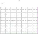
在本申请实施方式中,请参阅图2,图2为图1所示的触控面板的触控电极层的俯视结构示意图。所述触控电极层10包括多个触控区域10a,多个所述触控区域10a呈阵列分布,即多个所述触控区域10a呈多行多列排布。请参阅图3,图3为图2所示的触控面板的触控区域的结构示意图。每个所述触控区域10a包括多个触控点11,多个所述触控点11呈阵列分布,即多个所述触控区域10a呈多行多列排布。In the implementation manner of the present application, please refer to FIG. 2 , which is a schematic top view of the touch electrode layer of the touch panel shown in FIG. 1 . The
在本申请实施方式中,请参阅图4,图4为图1所示的触控面板的压力感应层的俯视结构示意图。所述压力感应层20包括多个感应组件21,多个所述感应组件21呈阵列分布,即多个所述感应组件21呈多行多列排布。多个所述感应组件21的位置分别与多个所述触控区域10a的位置相对应,即一个所述触控区域10a对应设置于一个所述感应组件21的上方。当所述触控面板1被触摸时,所述触控电极层10感应到至少一个触摸点,其中,至少一个所述触摸点包括一个实际触摸点,或者,包括多个实际触摸点与多个鬼点,也即为,多个所述触摸点包括至少两个所述实际触摸点,当所述实际触摸点为两个时,多个所述触摸点包括两个实际触摸点和至少一个所述鬼点。多个所述感应组件21用于感应压力点,以根据所述压力点确定所述实际触摸点所在的所述触控区域10a,即根据所述压力点确定所述实际触摸点所在的位置。其中,在所述触控面板1的厚度方向上,所述压力点与所述实际触摸点重合。In the embodiment of the present application, please refer to FIG. 4 , which is a schematic top view of the pressure sensing layer of the touch panel shown in FIG. 1 . The
可以理解的是,所述触控点11被触摸时,存在单点触摸与多点触摸两种情况。单点触摸时,所述触控电极层10感应到一个所述触摸点,该触摸点则为所述实际触摸点,所述触控电极层10就可以直接确定所述实际触摸点的位置。多点触摸时,所述触控电极层10感应到多个所述触摸点,多个所述触摸点中存在多个所述实际触摸点与多个所述鬼点,所述实际触摸点与所述鬼点的位置是不清楚的。因此,多个所述感应组件21感应到所述压力点,进而确定所述实际触摸点的位置,从而判断出所述触摸点是所述实际触摸点还是所述鬼点,避免了所述触控面板1感应到所述鬼点,提升了触控效果以及用户的使用体验。It can be understood that, when the
具体地,为便于说明,通过横纵坐标来定义不同所述触控区域10a,请参阅图2,Z(m,n)为触控区域,其中,m为横坐标,n为纵坐标。通过横坐标和纵坐标来定义不同所述触控点11,请参阅图3,D(x,y)为触控点,其中,x为横坐标,y为纵坐标。通过横坐标和纵坐标来定义不同所述感应组件21,请参阅图4,P(a,b)为触控区域,其中,a为横坐标,b为纵坐标。触控区域Z(m,n)的坐标分别与感应组件P(a,b)的坐标一一对应,即所述感应组件21的位置分别与所述触控区域10a的位置一一对应设置,例如,触控区域Z(m1,n1)与感应组件P(a1,b1)对应,触控区域Z(m4,n5)与感应组件P(a4,b5)对应。多点触摸时,所述触控电极层10感应到四个所述触摸点,例如,四个所述触摸点可分别在触控区域Z(m1,n1)、触控区域Z(m5,n1)、触控区域Z(m1,n5)、触控区域Z(m5,n5),其中,任意两个触控区域为所述实际触摸点所在的区域,另外两个触控区域为所述鬼点所在区域,而所述触控电极层10并不知道哪两个是实际触摸点,哪两个是鬼点。如果所述压力感应层20的感应组件P(a1,b1)与所述感应组件P(a5,b5)感应到所述压力点。因此,就可以得出所述触控区域Z(m1,n1)与触控区域Z(m5,n5)的所述触摸点为所述实际触摸点,而触控区域Z(m5,n1)与触控区域Z(m1,n5)的所述触摸点为所述鬼点。Specifically, for the convenience of description, the
在示例性实施方式中,每个所述触控区域Z(m,n)内的触控点D(x,y)的数量可为4个至100个,例如,4个、16个、25个、80个、100个、或其他数量个,本申请对此不作具体限制。例如,Z(m1,n1)由D(x1,y1)、D(x10,y1)、D(x1,y10)、D(x10,y10)连线构成,Z(m2,n1)由D(x11,y1)、D(x20,y1)、D(x11,y10)、D(x20,y10)连线构成。In an exemplary embodiment, the number of touch points D (x, y) in each touch area Z (m, n) may be 4 to 100, for example, 4, 16, 25 , 80, 100, or other numbers, the application does not specifically limit this. For example, Z(m1,n1) is composed of D(x1,y1), D(x10,y1), D(x1,y10), D(x10,y10), and Z(m2,n1) is composed of D(x11 , y1), D (x20, y1), D (x11, y10), D (x20, y10) are connected by lines.
在示例性实施方式中,所述触控区域Z(m,n)对应的面积一定要比手指与所述触控电极层10接触的面积要小,即所述触摸点对应多个所述触控区域Z(m,n)。在多点触摸时,避免多个所述触摸点在同一触控区域Z(m,n)内。In an exemplary embodiment, the area corresponding to the touch area Z (m, n) must be smaller than the area where the finger contacts the
在示例性实施方式中,所述触控电极层10还包括多个触控电极(图未示)与公共电极,多个所述触控电极设置于所述公共电极的一侧,每个所述触控电极对应一个所述触控点11,且所述触控电极与所述公共电极构成了等效电容。当所述触控电极层10被手指触摸时,手指与所述触控电极之间形成耦合电容,所述耦合电容与所述等效电容并联,使得被触摸的所述触控电极上的电容量增加。电容量增加的所述触控电极被侦测到,就得到被触摸的所述触控电极的坐标,即获得被触摸的所述触控点的坐标。In an exemplary embodiment, the
在示例性实施方式中,多个所述触控电极可对应一个触摸点。In an exemplary embodiment, a plurality of touch electrodes may correspond to one touch point.
在示例性实施方式中,手指直接与所述触控电极层10接触,而不与所述感应组件21接触。由于所述感应组件21也会通电,如果手指直接与所述感应组件21接触,会形成干扰电容,所述干扰电容会影响到所述触控电极层10的所述触控电极上的电容量,导致所述触控电极层10不能准确地感应所述触摸点。所述感应组件21可以通过感应压力来感应所述触摸点,即使间隔了所述触控电极层10,压力也可以准确地传递至所述感应组件21。因此,所述触控电极层10不会对所述感应组件21的感应灵敏度造成影响。In an exemplary embodiment, a finger directly contacts the
在示例性实施方式中,所述触控电极的形状可为四边形,例如,矩形、菱形等。所述触控电极的边长可分别为0.03mm至3mm,例如,0.03mm、0.1mm、0.5mm、1.2mm、2mm、2.5mm、3mm、或其他数值,可以根据触控的精度来具体设置所述触控电极的尺寸,本申请对此不作具体限制。In an exemplary embodiment, the shape of the touch electrodes may be a quadrilateral, for example, a rectangle, a rhombus, and the like. The side lengths of the touch electrodes can be 0.03mm to 3mm, for example, 0.03mm, 0.1mm, 0.5mm, 1.2mm, 2mm, 2.5mm, 3mm, or other values, which can be set according to the accuracy of the touch control The size of the touch electrodes is not specifically limited in this application.
在示例性实施方式中,所述触控电极的材料可为氧化铟锡(Indium Tin Oxide,ITO)。所述触控面板1主要应用于具有显示功能的电子设备上,由于氧化铟锡具有较好的透明性,使所述触控面板1可以透过电子设备发出的光线。In an exemplary embodiment, the material of the touch electrode may be indium tin oxide (Indium Tin Oxide, ITO). The
综上所述,本申请实施例提供的触控面板1包括触控电极层10和压力感应层20,所述触控电极层10包括多个触控区域10a,所述压力感应层20包括多个感应组件21,且多个所述感应组件21的位置分别与多个所述触控区域10a的位置一一对应。所述触控电极层10用于感应多个触摸点,其中,多个所述触摸点包括多个实际触摸点与多个鬼点。多个所述感应组件21用于感应压力点,以根据所述压力点确定所述实际触摸点的位置,从而判断出所述触摸点是所述实际触摸点还是所述鬼点,避免了所述触控面板1感应到所述鬼点,提升了触控效果以及用户的使用体验。同时,通过所述触控电极层10与所述压力感应层20来确定所述实际触摸点的位置,使所述触控面板1可以使用现有的触控电极层,且所述压力感应层20的所述感应组件21的数量也不必太多,避免了与所述感应组件21电连接的外围电路太过复杂,节约了制造成本。To sum up, the
在本申请实施方式中,请参阅图5与图6,图5为本申请实施例公开的感应组件处于未受压状态的结构示意图,图6为本申请实施例公开的感应组件处于受压状态的结构示意图。每个所述感应组件21包括柔性元件210与导电元件220,所述导电元件220连接于所述柔性元件210的一侧,且所述柔性元件210与所述导电元件220之间导通,即二者之间电连接。其中,所述柔性元件210在被触摸时发生形变,所述柔性元件210与所述导电元件220之间的接触面积增大,使所述感应组件21的阻值减小。In the embodiment of the present application, please refer to Fig. 5 and Fig. 6, Fig. 5 is a schematic structural diagram of the sensing component disclosed in the embodiment of the present application in an unpressurized state, and Fig. 6 is a schematic diagram of the sensing component disclosed in the embodiment of the present application in a pressurized state Schematic diagram of the structure. Each of the
在示例性实施方式中,释放对所述柔性元件210的触摸时,所述柔性元件210恢复原状,所述柔性元件210与所述导电元件220之间的接触面积减小,使所述感应组件21的阻值增大。In an exemplary embodiment, when the touch to the
在示例性实施方式中,所述柔性元件210可接入电源正极,所述导电元件220可接入电源负极;或,所述柔性元件210可接入电源负极,所述导电元件220可接入电源正极,使所述柔性元件210与所述导电元件220之间导通。当所述感应组件21阻值变化时,所述感应组件21内的电流发生变化。In an exemplary embodiment, the
在示例性实施方式中,所述柔性元件210连接于所述触控电极层10的一侧,所述导电元件220连接于所述柔性元件210背对所述触控电极层10的一侧。In an exemplary embodiment, the
可以理解的是,所述柔性元件210直接与所述触控电极层10接触,所述触控电极层10被触摸时,所述触控电极层10的被触摸处会发生一定的形变,进而使所述柔性元件210发生形变。It can be understood that the
在示例性实施方式中,所述柔性元件210的材料可包括聚二甲基硅氧烷,所述导电元件220的材料可包括聚苯胺。In an exemplary embodiment, the material of the
可以理解的是,聚二甲基硅氧烷具有优异的柔性率与形变率,其在很小的压力下就可以发生形变,而且,在压力撤销时,聚二甲基硅氧烷可以很快的恢复原状。聚苯胺具有良好的导电性能、化学稳定性。通过对本申请的所述感应组件21进行试验测试,所述感应组件21可以感应的压力范围为1mg至1500g,所述感应组件21的响应时间小于50ms,所述感应组件21的所述柔性元件210形变后的恢复时间小于60ms,从而使得所述感应组件21可以快速地感应微小的触摸,且灵敏度较高。It can be understood that polydimethylsiloxane has excellent flexibility and deformation rate, and it can be deformed under a small pressure, and when the pressure is released, polydimethylsiloxane can quickly of restoration. Polyaniline has good electrical conductivity and chemical stability. Through the experimental test of the
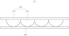
在本申请实施方式中,请参阅图5与图6,所述柔性元件210包括基底211与多个凸起结构212,所述基底211与所述导电元件220相对且间隔设置,多个所述凸起结构212连接于所述基底211与所述导电元件220之间,即所述凸起结构212的一端固定于所述基底211,相对的另一端接触所述导电元件220。也即为,多个所述凸起结构212连接于所述基底211面对所述导电元件220的一侧,并与所述导电元件220接触。如图6所示,所述基底211在被触摸时发生形变,使多个所述凸起结构212朝向所述导电元件220移动。由于所述导电元件220抵持,多个所述凸起结构212发生形变,使多个所述凸起结构212与所述导电元件220的接触面积增大,则所述感应组件21的阻值减小。In the embodiment of the present application, please refer to FIG. 5 and FIG. 6, the
可以理解的是,多个所述凸起结构212与所述导电元件220的接触面积增大,使电流流过的面积增大,进而减小了所述感应组件21的电阻。It can be understood that the increased contact area between the plurality of protruding
在本申请实施方式中,在所述基底211指向所述导电元件220的方向上,所述凸起结构212的横截面的面积减小,使得所述凸起结构212朝向所述导电元件220移动时所述凸起结构212与所述导电元件220之间的接触面积增大。In the embodiment of the present application, in the direction in which the base 211 points to the
在示例性实施方式中,所述凸起结构212的形状可为半球或半椭球。在其他实施方式中,所述凸起结构212的形状可为圆台、棱台、或其他能满足相同要求的形状,本申请对此不作具体限制。In an exemplary embodiment, the shape of the protruding
在示例性实施方式中,所述凸起结构212的高度可为8um至30um,例如,8um、10um、15um、18um、21um、25um、30um、或其他数值,本申请对此不作具体限制。In an exemplary embodiment, the height of the protruding
在示例性实施方式中,所述凸起结构212的底部的直径可为10um至30um,例如,10um、12um、15um、19um、20um、24um、30um、或其他数值,本申请对此不作具体限制。In an exemplary embodiment, the diameter of the bottom of the raised
在示例性实施方式中,所述导电元件220可为一薄膜,其厚度可为100nm至300nm,例如,100nm、150nm、180nm、200nm、250nm、270nm、300nm、或其他数值,本申请对此不作具体限制。In an exemplary embodiment, the
在本申请实施方式中,请参阅图7,图7为本申请实施例公开的坐标侦测单元与触控电极层的结构示意图,所述触控面板1还包括坐标侦测单元40,所述坐标侦测单元40与所述触控电极层10电连接,所述坐标侦测单元40用于侦测每个所述触控点的电容以获取所述触摸点的坐标,并输出所述触摸点的坐标信号至对比单元(图未示)。In the embodiment of the present application, please refer to FIG. 7 . FIG. 7 is a schematic structural diagram of the coordinate detection unit and the touch electrode layer disclosed in the embodiment of the present application. The
在示例性实施方式中,所述坐标侦测单元40与所述触控电极层10的每个所述触控电极电连接。In an exemplary embodiment, the coordinate
在本申请实施方式中,请参阅图8,图8为本申请实施例公开的压力侦测单元与压力感应层的结构示意图,所述触控面板1还包括压力侦测单元50,所述压力侦测单元50分别与所述压力感应层20的每个所述感应组件21电连接,所述压力侦测单元50用于侦测每个所述感应组件21的电流以获取所述压力点的坐标,并输出所述压力点的坐标信号至所述对比单元。In the embodiment of the present application, please refer to FIG. 8 . FIG. 8 is a schematic structural diagram of the pressure detection unit and the pressure sensing layer disclosed in the embodiment of the present application. The
在示例性实施方式中,所述坐标侦测单元40与所述压力侦测单元50可集成于Flash存储器中。In an exemplary embodiment, the coordinate
在本申请实施方式中,所述触控面板1还可以包括对比单元,所述对比单元分别与所述坐标侦测单元40以及所述压力侦测单元50电连接。所述对比单元从所述坐标侦测单元40接收所述触摸点的坐标信号以及从所述压力侦测单元50接收所述压力点的坐标信号,并根据所述触摸点的坐标信号与所述压力点的坐标信号判断所述触摸点是否有相对应的所述压力点。若所述触摸点有相对应的所述压力点,则所述触摸点为实际触摸点;若所述触摸点没有相对应的所述压力点,则所述触摸点为鬼点。所述对比单元还用于输出所述实际触摸点的坐标信号至驱动模块500(见图10)。In the embodiment of the present application, the
在示例性实施方式中,所述对比单元可集成于逻辑板(Timer Control Register,Tcon)内。In an exemplary embodiment, the comparison unit may be integrated into a logic board (Timer Control Register, Tcon).
综上所述,本申请实施例提供的触控面板1包括触控电极层10,所述触控电极层10包括多个触控区域10a。所述触控面板1还包括压力感应层20,所述压力感应层20包括多个感应组件21,且多个所述感应组件21的位置分别与多个所述触控区域10a的位置相对应。所述触控电极层10用于感应多个触摸点,其中,多个所述触摸点包括多个实际触摸点与多个鬼点。多个所述感应组件21用于感应压力点,以根据所述压力点确定所述实际触摸点的位置,从而判断出所述触摸点是所述实际触摸点还是所述鬼点,避免了所述触控面板1感应到所述鬼点,提升了触控效果以及用户的使用体验。To sum up, the
基于同样的发明构思,本申请实施例还提供一种显示模组,请参阅图9,图9为本申请实施例公开的显示模组的层结构示意图。所述显示模组400包括显示面板300和上述的触控面板1,所述触控面板1设置于所述显示面板300的出光侧。由于图1至图8所示的实施例中已对触控面板1进行了较为详细的阐述,在此不再赘述。Based on the same inventive concept, the embodiment of the present application further provides a display module, please refer to FIG. 9 , which is a schematic layer structure diagram of the display module disclosed in the embodiment of the present application. The
在示例性实施方式中,所述显示面板300可为液晶显示面板(Liquid CrystalDisplay,LCD)、有机发光二极管(Organic Light-Emitting Diode,OLED)显示面板或微米发光二极管(Micro Light-Emitting Diode,Micro LED)显示面板,本申请对此不作具体限制。In an exemplary embodiment, the
综上所述,本申请实施例提供的显示模组400包括显示面板300与触控面板1,所述触控面板1包括触控电极层10和压力感应层20,所述触控电极层10包括多个触控区域10a,所述压力感应层20包括多个感应组件21,且多个所述感应组件21的位置分别与多个所述触控区域10a的位置相对应。所述触控电极层10用于感应多个触摸点,其中,多个所述触摸点包括多个实际触摸点与多个鬼点。多个所述感应组件21用于感应压力点,以根据所述压力点确定所述实际触摸点的位置,从而判断出所述触摸点是所述实际触摸点还是所述鬼点,避免了所述触控面板1感应到所述鬼点,提升了触控效果以及用户的使用体验。To sum up, the
基于同样的发明构思,本申请实施例还提供一种显示装置,请参阅图10,图10为本申请实施例公开的显示装置的结构示意图。所述显示装置600包括驱动模块500以及上述的显示模组400,所述驱动模块500与所述显示模组400电连接,所述驱动模块500向所述显示模组400传输控制信号。由于图9所示的实施例中已对所述显示模组400进行了较为详细的阐述,在此不再赘述。Based on the same inventive concept, the embodiment of the present application further provides a display device, please refer to FIG. 10 , which is a schematic structural diagram of the display device disclosed in the embodiment of the present application. The
在本申请实施方式中,所述驱动模块500可分别与所述显示面板300以及所述触控面板1的所述对比单元电连接。所述驱动模块500用于接收所述实际触摸点的坐标信号,并根据所述实际触摸点的坐标信号控制所述显示面板300显示相应的画面。In the implementation manner of the present application, the
可以理解地,所述显示装置600可用于包括但不限于电视、平板电脑、笔记本电脑、台式电脑、移动电话、车载显示器、智能手表、智能手环、智能眼镜等电子设备。根据本申请的实施例,所述显示装置600的具体种类不受特别的限制,本领域技术人员可根据所述显示装置600的具体使用要求进行相应地设计,在此不再赘述。It can be understood that the
在示例性实施方式中,所述显示装置600还可以包括电源板、高压板以及按键控制板等其他必要的部件和组成部分,本领域技术人员可根据所述显示装置600的具体类型和实际功能进行相应地补充,在此不再赘述。In an exemplary embodiment, the
综上所述,本申请实施例提供的显示装置600包括驱动模块500与显示模组400,所述显示模组400包括显示面板300与触控面板1,所述触控面板1包括触控电极层10,所述触控电极层10包括多个触控区域10a。所述触控面板1还包括压力感应层20,所述压力感应层20包括多个感应组件21,且多个所述感应组件21的位置分别与多个所述触控区域10a的位置一一对应。所述触控电极层10用于感应多个触摸点,其中,多个所述触摸点包括多个实际触摸点与多个鬼点。多个所述感应组件21用于感应压力点,以根据所述压力点确定所述实际触摸点的位置,从而判断出所述触摸点是所述实际触摸点还是所述鬼点,避免了所述触控面板1感应到所述鬼点,提升了触控效果以及用户的使用体验。In summary, the
基于同样的发明构思,本申请实施例还提供一种触控侦测方法,所述触控侦测方法由上述的触控面板1执行,所述触控侦测方法与所述触控面板1相同之处的描述,请参阅上述图1至图8所示实施例关于所述触控面板1的描述,在此不再赘述。请参阅图11,图11为本申请实施例公开的触控侦测方法的流程示意图,所述触控侦测方法包括以下步骤。Based on the same inventive concept, the embodiment of the present application also provides a touch detection method, the touch detection method is executed by the
S10、提供一触控面板1,所述触控面板1包括具有多个触控区域10a的触控电极层10以及具有多个感应组件21的压力感应层20,每个所述触控区域10a内具有多个触控点11,多个所述触控区域10a的位置与多个所述感应组件21的位置相对应。S10, providing a
在示例性实施方式中,所述触控电极层10设置于所述压力感应层20的一侧。多个所述触控区域10a呈阵列分布,多个触控点11呈阵列分布,多个所述感应组件21呈阵列分布。多个所述触控区域10a的位置与多个所述感应组件21的位置一一对应,且所述触控区域10a与所述感应组件21重合。In an exemplary embodiment, the
S20、侦测所述触控电极层10的每个所述触控点11的电容以获取多个触摸点的坐标,侦测每个所述感应组件21的电流以获取压力点的坐标,其中,所述触摸点包括多个实际触摸点与多个鬼点。S20. Detect the capacitance of each
具体地,所述触控面板1还包括坐标侦测单元40和压力侦测单元50,所述坐标侦测单元40与所述触控电极层10电连接,所述压力侦测单元50分别与所述压力感应层20的每个所述感应组件21电连接。可通过所述坐标侦测单元40侦测所述触控电极层10的每个所述触控点11的电容以获取多个触摸点的坐标,并可通过所述压力侦测单元50侦测每个所述感应组件21的电流以获取压力点的坐标。Specifically, the
S30、判断所述触摸点是否有相对应的所述压力点,其中,若所述触摸点有相对应的所述压力点,则所述触摸点为所述实际触摸点;若所述触摸点没有相对应的所述压力点,则所述触摸点为所述鬼点。S30. Determine whether the touch point has a corresponding pressure point, wherein, if the touch point has a corresponding pressure point, the touch point is the actual touch point; if the touch point If there is no corresponding pressure point, the touch point is the ghost point.
具体地,所述触控面板1还可以包括对比单元,所述对比单元分别与所述坐标侦测单元40以及所述压力侦测单元50电连接,并从所述坐标侦测单元40接收所述触摸点的坐标信号以及从所述压力侦测单元50接收所述压力点的坐标信号。通过所述对比单元根据所述触摸点的坐标信号与所述压力点的坐标信号判断所述触摸点是否有相对应的所述压力点,并输出所述实际触摸点的坐标信号。Specifically, the
综上所述,本申请实施例提供的触控侦测方法包括:提供一触控面板1,所述触控面板1包括具有多个触控区域10a的触控电极层10以及具有多个感应组件21的压力感应层20,每个触控区域10a内具有多个触控点11,多个所述触控区域10a的位置与多个所述感应组件21的位置相对应;侦测所述触控电极层10的每个所述触控点11的电容以获取多个触摸点的坐标,侦测每个所述感应组件21的电流以获取压力点的坐标,其中,所述触摸点包括多个实际触摸点与多个鬼点;判断所述触摸点是否有相对应的所述压力点,其中,若所述触摸点有相对应的所述压力点,则所述触摸点为所述实际触摸点;若所述触摸点没有相对应的所述压力点,则所述触摸点为所述鬼点。因此,本申请的触控侦测方法通过所述压力感应层20的压力点来确定所述实际触摸点的位置,从而判断出所述触摸点是所述实际触摸点还是所述鬼点,避免了所述触控面板1感应到所述鬼点,提升了触控效果以及用户的使用体验。To sum up, the touch detection method provided by the embodiment of the present application includes: providing a
本申请中所描述的流程图仅仅为一个实施例,在不偏离本申请的精神的情况下对此图示或者本申请中的步骤可以有多种修改变化。比如,可以不同次序的执行这些步骤,或者可以增加、删除或者修改某些步骤。本领域的一般技术人员可以理解实现上述实施例的全部或部分流程,并依本申请权利要求所作的等同变化,仍属于本申请所涵盖的范围。The flowchart described in this application is only an embodiment, and there may be various modifications and changes to this illustration or the steps in this application without departing from the spirit of this application. For example, the steps may be performed in a different order, or certain steps may be added, deleted or modified. Those skilled in the art can understand that all or part of the processes of the above embodiments are realized, and equivalent changes made according to the claims of the present application still fall within the scope of the present application.
需要理解的是,术语“第一”、“第二”等仅用于描述目的,而不能理解为指示或暗示相对重要性或者隐含指明所指示的技术特征的数量。由此,限定有“第一”、“第二”的特征可以明示或者隐含地包括一个或者更多个所述特征。在本申请的实施方式的描述中,“多个”的含义是两个或两个以上,除非另有明确具体的限定。It should be understood that the terms "first", "second" and so on are used for descriptive purposes only, and cannot be interpreted as indicating or implying relative importance or implicitly specifying the quantity of indicated technical features. Thus, a feature defined as "first" or "second" may explicitly or implicitly include one or more of said features. In the description of the embodiments of the present application, "plurality" means two or more, unless otherwise specifically defined.
在本说明书的描述中,参考术语“一个实施方式”、“一些实施方式”、“示意性实施方式”、“示例”、“具体示例”或“一些示例”等的描述意指结合所述实施方式或示例描述的具体特征、结构或者特点包含于本申请的至少一个实施方式或示例中。在本说明书中,对上述术语的示意性表述不一定指的是相同的实施方式或示例。而且,描述的具体特征、结构或者特点可以在任何的一个或多个实施方式或示例中以合适的方式结合。In the description of this specification, reference to the terms "one embodiment", "some embodiments", "exemplary embodiments", "example", "specific examples" or "some examples" etc. Specific features, structures, or features described in modes or examples are included in at least one embodiment or example of the present application. In this specification, schematic representations of the above terms do not necessarily refer to the same embodiment or example. Furthermore, the described specific features, structures or characteristics may be combined in any suitable manner in any one or more embodiments or examples.
应当理解的是,本申请的应用不限于上述的举例,对本领域普通技术人员来说,可以根据上述说明加以改进或变换,所有这些改进和变换都应属于本申请所附权利要求的保护范围。本领域的一般技术人员可以理解实现上述实施例的全部或部分流程,并依本申请权利要求所作的等同变化,仍属于本申请所涵盖的范围。It should be understood that the application of the present application is not limited to the above examples, and those skilled in the art can make improvements or changes based on the above descriptions, and all these improvements and changes should belong to the protection scope of the appended claims of the present application. Those skilled in the art can understand that all or part of the processes of the above embodiments are realized, and equivalent changes made according to the claims of the present application still fall within the scope of the present application.
Claims (10)
Priority Applications (2)
| Application Number | Priority Date | Filing Date | Title |
|---|---|---|---|
| CN202310518763.4ACN116243815B (en) | 2023-05-10 | 2023-05-10 | Touch panel, display module, display device and touch detection method |
| US18/645,828US20240377913A1 (en) | 2023-05-10 | 2024-04-25 | Touch panel, display module, and display device |
Applications Claiming Priority (1)
| Application Number | Priority Date | Filing Date | Title |
|---|---|---|---|
| CN202310518763.4ACN116243815B (en) | 2023-05-10 | 2023-05-10 | Touch panel, display module, display device and touch detection method |
Publications (2)
| Publication Number | Publication Date |
|---|---|
| CN116243815Atrue CN116243815A (en) | 2023-06-09 |
| CN116243815B CN116243815B (en) | 2023-08-08 |
Family
ID=86633402
Family Applications (1)
| Application Number | Title | Priority Date | Filing Date |
|---|---|---|---|
| CN202310518763.4AActiveCN116243815B (en) | 2023-05-10 | 2023-05-10 | Touch panel, display module, display device and touch detection method |
Country Status (2)
| Country | Link |
|---|---|
| US (1) | US20240377913A1 (en) |
| CN (1) | CN116243815B (en) |
Citations (16)
| Publication number | Priority date | Publication date | Assignee | Title |
|---|---|---|---|---|
| JPH08171447A (en)* | 1994-12-20 | 1996-07-02 | Matsushita Electric Ind Co Ltd | Information input device |
| CN102163100A (en)* | 2011-04-01 | 2011-08-24 | 深圳清华大学研究院 | Contact positioning method and device for electronic touch screen |
| CN103713793A (en)* | 2013-12-31 | 2014-04-09 | 王文洲 | Locating method for self-capacitance type touch screen |
| CN104598066A (en)* | 2013-10-30 | 2015-05-06 | 松下电器产业株式会社 | Pressure-sensitive switch, manufacturing method for same, touch panel including pressure-sensitive switch, and manufacturing method for touch panel |
| CN106775087A (en)* | 2016-12-16 | 2017-05-31 | 广东欧珀移动通信有限公司 | A kind of touch-screen control method of mobile terminal, device and mobile terminal |
| CN106919283A (en)* | 2017-02-20 | 2017-07-04 | 北京小米移动软件有限公司 | The touch event processing method of terminal, device and terminal |
| WO2017113761A1 (en)* | 2015-12-31 | 2017-07-06 | 深圳市汇顶科技股份有限公司 | Method and device for detecting valid touch point via pressure |
| CN107340897A (en)* | 2016-04-29 | 2017-11-10 | 鸿富锦精密工业(深圳)有限公司 | Pressure-sensing module and touch display substrate |
| US20180018044A1 (en)* | 2016-07-14 | 2018-01-18 | Samsung Display Co., Ltd. | Touch sensor and display device having the same |
| CN111665989A (en)* | 2020-06-09 | 2020-09-15 | 京东方科技集团股份有限公司 | Touch device, manufacturing method thereof, touch method and electronic equipment |
| CN111762023A (en)* | 2020-05-29 | 2020-10-13 | 法雷奥舒适驾驶辅助系统(广州)有限公司 | Touch device and method thereof and auxiliary switch of automobile steering wheel |
| US20200371634A1 (en)* | 2018-01-31 | 2020-11-26 | Mitsubishi Electric Corporation | Touch panel device |
| CN112214132A (en)* | 2020-10-19 | 2021-01-12 | 深圳市捷诚技术服务有限公司 | False touch correction method and device, computer readable medium and electronic equipment |
| CN112817483A (en)* | 2021-01-29 | 2021-05-18 | 网易(杭州)网络有限公司 | Multi-point touch processing method, device, equipment and storage medium |
| CN113495641A (en)* | 2020-04-07 | 2021-10-12 | 宇龙计算机通信科技(深圳)有限公司 | Touch screen ghost point identification method and device, terminal and storage medium |
| CN114935982A (en)* | 2022-05-23 | 2022-08-23 | 深圳市爱协生科技有限公司 | Display components and electronic equipment |
- 2023
- 2023-05-10CNCN202310518763.4Apatent/CN116243815B/enactiveActive
- 2024
- 2024-04-25USUS18/645,828patent/US20240377913A1/enactivePending
Patent Citations (16)
| Publication number | Priority date | Publication date | Assignee | Title |
|---|---|---|---|---|
| JPH08171447A (en)* | 1994-12-20 | 1996-07-02 | Matsushita Electric Ind Co Ltd | Information input device |
| CN102163100A (en)* | 2011-04-01 | 2011-08-24 | 深圳清华大学研究院 | Contact positioning method and device for electronic touch screen |
| CN104598066A (en)* | 2013-10-30 | 2015-05-06 | 松下电器产业株式会社 | Pressure-sensitive switch, manufacturing method for same, touch panel including pressure-sensitive switch, and manufacturing method for touch panel |
| CN103713793A (en)* | 2013-12-31 | 2014-04-09 | 王文洲 | Locating method for self-capacitance type touch screen |
| WO2017113761A1 (en)* | 2015-12-31 | 2017-07-06 | 深圳市汇顶科技股份有限公司 | Method and device for detecting valid touch point via pressure |
| CN107340897A (en)* | 2016-04-29 | 2017-11-10 | 鸿富锦精密工业(深圳)有限公司 | Pressure-sensing module and touch display substrate |
| US20180018044A1 (en)* | 2016-07-14 | 2018-01-18 | Samsung Display Co., Ltd. | Touch sensor and display device having the same |
| CN106775087A (en)* | 2016-12-16 | 2017-05-31 | 广东欧珀移动通信有限公司 | A kind of touch-screen control method of mobile terminal, device and mobile terminal |
| CN106919283A (en)* | 2017-02-20 | 2017-07-04 | 北京小米移动软件有限公司 | The touch event processing method of terminal, device and terminal |
| US20200371634A1 (en)* | 2018-01-31 | 2020-11-26 | Mitsubishi Electric Corporation | Touch panel device |
| CN113495641A (en)* | 2020-04-07 | 2021-10-12 | 宇龙计算机通信科技(深圳)有限公司 | Touch screen ghost point identification method and device, terminal and storage medium |
| CN111762023A (en)* | 2020-05-29 | 2020-10-13 | 法雷奥舒适驾驶辅助系统(广州)有限公司 | Touch device and method thereof and auxiliary switch of automobile steering wheel |
| CN111665989A (en)* | 2020-06-09 | 2020-09-15 | 京东方科技集团股份有限公司 | Touch device, manufacturing method thereof, touch method and electronic equipment |
| CN112214132A (en)* | 2020-10-19 | 2021-01-12 | 深圳市捷诚技术服务有限公司 | False touch correction method and device, computer readable medium and electronic equipment |
| CN112817483A (en)* | 2021-01-29 | 2021-05-18 | 网易(杭州)网络有限公司 | Multi-point touch processing method, device, equipment and storage medium |
| CN114935982A (en)* | 2022-05-23 | 2022-08-23 | 深圳市爱协生科技有限公司 | Display components and electronic equipment |
Also Published As
| Publication number | Publication date |
|---|---|
| US20240377913A1 (en) | 2024-11-14 |
| CN116243815B (en) | 2023-08-08 |
Similar Documents
| Publication | Publication Date | Title |
|---|---|---|
| US9483145B2 (en) | Touch panel and a manufacturing method thereof | |
| CN205038626U (en) | In cell touch panel and display device | |
| CN102955311B (en) | A kind of liquid crystal indicator of embedded touch control | |
| CN205121513U (en) | In cell touch panel and display device | |
| US20090096760A1 (en) | Capacitance type touch panel | |
| EP2555095A2 (en) | Touch panel and method for manufacturing the same | |
| KR20130124084A (en) | Sensor for detecting proximity/motion and touch and display device having the same | |
| CN204087159U (en) | A kind of touch-screen and display panel | |
| JPWO2012096210A1 (en) | Coordinate input device | |
| CN105824475B (en) | A kind of preparation method of display panel, display device and display panel | |
| CN104834121B (en) | Touch base plate, display panel, display device and touch control method | |
| CN206479966U (en) | A kind of touch-control display panel and display device | |
| WO2018028010A1 (en) | Screen and display | |
| US20120249469A1 (en) | Display with touch control function | |
| CN104076993A (en) | Touch display panel, touch positioning method and display device | |
| CN101937278B (en) | Touch panel with asymmetric conductive pattern and related device and method | |
| CN101644974A (en) | Touch panel, manufacture method thereof and touch type display device | |
| CN116243815B (en) | Touch panel, display module, display device and touch detection method | |
| CN104731391A (en) | Touch control type keyboard | |
| TWI531844B (en) | Capacitive touch panel and controlling method thereof | |
| CN102645997A (en) | Touch control panel and touch point distinguishing method of touch control panel | |
| CN105739797A (en) | Touch sensing system including touch screen panel | |
| CN103970374A (en) | Touch control unit and touch control panel | |
| CN106201112A (en) | A kind of pressure touch display device and touch-control pressure detection method thereof | |
| CN205563527U (en) | Touch display panel |
Legal Events
| Date | Code | Title | Description |
|---|---|---|---|
| PB01 | Publication | ||
| PB01 | Publication | ||
| SE01 | Entry into force of request for substantive examination | ||
| SE01 | Entry into force of request for substantive examination | ||
| GR01 | Patent grant | ||
| GR01 | Patent grant |