CN116242253A - Underwater concrete apparent laser line three-dimensional scanning measurement method - Google Patents
Underwater concrete apparent laser line three-dimensional scanning measurement methodDownload PDFInfo
- Publication number
- CN116242253A CN116242253ACN202310527270.7ACN202310527270ACN116242253ACN 116242253 ACN116242253 ACN 116242253ACN 202310527270 ACN202310527270 ACN 202310527270ACN 116242253 ACN116242253 ACN 116242253A
- Authority
- CN
- China
- Prior art keywords
- laser line
- laser
- imaging
- camera
- point
- Prior art date
- Legal status (The legal status is an assumption and is not a legal conclusion. Google has not performed a legal analysis and makes no representation as to the accuracy of the status listed.)
- Granted
Links
Images


Classifications
- G—PHYSICS
- G01—MEASURING; TESTING
- G01B—MEASURING LENGTH, THICKNESS OR SIMILAR LINEAR DIMENSIONS; MEASURING ANGLES; MEASURING AREAS; MEASURING IRREGULARITIES OF SURFACES OR CONTOURS
- G01B11/00—Measuring arrangements characterised by the use of optical techniques
- G01B11/002—Measuring arrangements characterised by the use of optical techniques for measuring two or more coordinates
- G—PHYSICS
- G01—MEASURING; TESTING
- G01N—INVESTIGATING OR ANALYSING MATERIALS BY DETERMINING THEIR CHEMICAL OR PHYSICAL PROPERTIES
- G01N21/00—Investigating or analysing materials by the use of optical means, i.e. using sub-millimetre waves, infrared, visible or ultraviolet light
- G01N21/84—Systems specially adapted for particular applications
- G01N21/88—Investigating the presence of flaws or contamination
- G01N21/8851—Scan or image signal processing specially adapted therefor, e.g. for scan signal adjustment, for detecting different kinds of defects, for compensating for structures, markings, edges
- G—PHYSICS
- G06—COMPUTING OR CALCULATING; COUNTING
- G06T—IMAGE DATA PROCESSING OR GENERATION, IN GENERAL
- G06T7/00—Image analysis
- G06T7/80—Analysis of captured images to determine intrinsic or extrinsic camera parameters, i.e. camera calibration
- G—PHYSICS
- G01—MEASURING; TESTING
- G01N—INVESTIGATING OR ANALYSING MATERIALS BY DETERMINING THEIR CHEMICAL OR PHYSICAL PROPERTIES
- G01N21/00—Investigating or analysing materials by the use of optical means, i.e. using sub-millimetre waves, infrared, visible or ultraviolet light
- G01N21/84—Systems specially adapted for particular applications
- G01N21/88—Investigating the presence of flaws or contamination
- G01N21/8851—Scan or image signal processing specially adapted therefor, e.g. for scan signal adjustment, for detecting different kinds of defects, for compensating for structures, markings, edges
- G01N2021/8887—Scan or image signal processing specially adapted therefor, e.g. for scan signal adjustment, for detecting different kinds of defects, for compensating for structures, markings, edges based on image processing techniques
- G—PHYSICS
- G06—COMPUTING OR CALCULATING; COUNTING
- G06T—IMAGE DATA PROCESSING OR GENERATION, IN GENERAL
- G06T2207/00—Indexing scheme for image analysis or image enhancement
- G06T2207/30—Subject of image; Context of image processing
- G06T2207/30244—Camera pose
- Y—GENERAL TAGGING OF NEW TECHNOLOGICAL DEVELOPMENTS; GENERAL TAGGING OF CROSS-SECTIONAL TECHNOLOGIES SPANNING OVER SEVERAL SECTIONS OF THE IPC; TECHNICAL SUBJECTS COVERED BY FORMER USPC CROSS-REFERENCE ART COLLECTIONS [XRACs] AND DIGESTS
- Y02—TECHNOLOGIES OR APPLICATIONS FOR MITIGATION OR ADAPTATION AGAINST CLIMATE CHANGE
- Y02A—TECHNOLOGIES FOR ADAPTATION TO CLIMATE CHANGE
- Y02A90/00—Technologies having an indirect contribution to adaptation to climate change
- Y02A90/30—Assessment of water resources
Landscapes
- Physics & Mathematics (AREA)
- General Physics & Mathematics (AREA)
- Engineering & Computer Science (AREA)
- Computer Vision & Pattern Recognition (AREA)
- Signal Processing (AREA)
- Health & Medical Sciences (AREA)
- Life Sciences & Earth Sciences (AREA)
- Chemical & Material Sciences (AREA)
- Analytical Chemistry (AREA)
- Biochemistry (AREA)
- General Health & Medical Sciences (AREA)
- Immunology (AREA)
- Pathology (AREA)
- Theoretical Computer Science (AREA)
- Length Measuring Devices By Optical Means (AREA)
Abstract
Description
Translated fromChinese技术领域technical field
本发明属于水基础设施安全测量技术领域,具体涉及一种水下混凝土表观激光线三维扫描测量方法。The invention belongs to the technical field of water infrastructure safety measurement, and in particular relates to a three-dimensional scanning measurement method of underwater concrete surface laser line.
背景技术Background technique
高坝大库、桥梁港口、输引水隧洞等是保障防洪安全、支撑水资源综合开发利用的重大涉水基础设施。在长期服役过程中,由地震、地质、洪涝等灾害引起基础设施水下混凝土结构缺陷,如裂缝、冲坑、磨蚀、露筋等,是影响工程安全运行的关键,需要及时、准确的缺陷检测和隐患排查。目前水下混凝土表观三维测量主要采用激光扫描的方法进行测量,但在自然流域中由于水体浑浊以及水体对激光线的吸收与散射,导致水下激光线三维扫描并不能采集到有效的三维点云数据。High dams, large reservoirs, bridges and ports, and water transmission and diversion tunnels are major wading infrastructures that ensure flood control safety and support the comprehensive development and utilization of water resources. During the long-term service, the defects of the underwater concrete structure of the infrastructure caused by earthquakes, geology, floods and other disasters, such as cracks, scoured pits, abrasions, exposed bars, etc., are the key to the safe operation of the project, and timely and accurate defect detection is required and hidden danger investigation. At present, the apparent three-dimensional measurement of underwater concrete is mainly carried out by laser scanning method. However, in natural watersheds, due to the turbidity of the water body and the absorption and scattering of the laser line by the water body, the effective three-dimensional point cannot be collected by underwater laser line three-dimensional scanning. cloud data.
利用当前的水下激光线三维扫描设备在清水环境中能采集到点云图象数据,但是由于在不同的水域环境中水体溶解杂质不同介质的折射率也不同,因此在不同清水环境中采集到的点云图像数据其测量精度也不能有效保证。The current underwater laser line 3D scanning equipment can collect point cloud image data in clear water environments. However, due to the different refractive indices of dissolved impurities in water bodies and different media in different water environments, the data collected in different clear water environments The measurement accuracy of the point cloud image data cannot be effectively guaranteed.
发明内容Contents of the invention
针对现有技术中的上述不足,本发明提供的水下混凝土表观激光线三维扫描测量方法消除了浊水环境对激光线扫描的影响,建立了激光线扫描成像的归一化模型消除了折射畸变的影响。In view of the above-mentioned deficiencies in the prior art, the three-dimensional laser line scanning measurement method for the underwater concrete surface provided by the present invention eliminates the influence of the turbid water environment on the laser line scan, and establishes a normalized model of the laser line scan imaging to eliminate the refraction Distortion effects.
为了达到上述发明目的,本发明采用的技术方案为:一种水下混凝土表观激光线三维扫描测量方法,包括以下步骤In order to achieve the purpose of the above invention, the technical solution adopted in the present invention is: a method for measuring the apparent laser line three-dimensional scanning of underwater concrete, comprising the following steps
S1、对清水置换装置内的激光线扫描成像设备进行激光线平面标定,构建激光平面方程;S1. Calibrate the laser line plane of the laser line scan imaging equipment in the clean water replacement device, and construct the laser plane equation;
S2、建立光线在不同介质表面的光线追踪模型,进而建立真实像点与相机成像点之间的多介质折射模型;S2. Establish a ray tracing model of light on the surface of different media, and then establish a multi-media refraction model between the real image point and the camera imaging point;
S3、将多介质折射模型与相机成像模型融合,获得水下成像的归一化模型;S3. Merging the multi-media refraction model with the camera imaging model to obtain a normalized model for underwater imaging;
S4、利用归一化模型和激光平面方程将获取的水下混凝土表观激光线图像转换至对应空气中的激光线图像中,实现水下混凝土表观激光线三维扫描测量。S4. Using the normalized model and the laser plane equation, the obtained underwater concrete apparent laser line image is converted into the corresponding laser line image in the air, so as to realize the three-dimensional scanning measurement of the underwater concrete apparent laser line.
进一步地,所述步骤S1具体为:Further, the step S1 is specifically:
S11、将激光线扫描成像设备密封置于清水置换装置中;S11. Sealing the laser line scan imaging device in the water replacement device;
其中,清水置换装置为内含清水的玻璃块组成的密封结构,用于放置激光扫描成像设备,当水域水质浑浊影响激光扫描成像设备成像时,通过清水置换装置中的清水替换激光扫描成像设备中相机与被测物体间的浑浊水,以获取被测物体的清晰成像;Among them, the clear water replacement device is a sealed structure composed of glass blocks containing clear water, which is used to place the laser scanning imaging equipment. When the water quality in the water area is turbid and affects the imaging of the laser scanning imaging equipment, the clean water in the clear water replacement device replaces the laser scanning imaging equipment. The turbid water between the camera and the measured object to obtain a clear image of the measured object;
S12、利用激光线扫描成像设备扫描获取图像对相机参数进行标定;S12. Using a laser line scan imaging device to scan and obtain an image to calibrate the camera parameters;
S13、基于参数标定的相机,利用交比不变性对激光平面方程进行标定,构建激光平面方程。S13. Based on the parameter calibration camera, the laser plane equation is calibrated by using cross-ratio invariance, and the laser plane equation is constructed.
进一步地,所述步骤S11中,激光线扫描成像设备中的激光线在相机视场所成的像在视野正中央。Further, in the step S11, the image formed by the laser line in the laser line scanning imaging device in the field of view of the camera is in the center of the field of view.
进一步地,所述步骤S13中,交比不变性的表达式为:Further, in the step S13, the expression of cross-ratio invariance is:

式中,


所述步骤S13中,对激光平面方程进行标定的方法为:In the step S13, the method for calibrating the laser plane equation is:
利用激光线与标定板的角点的交线确定Q点在图像坐标系中的坐标,利用交比不变性确定Q点在世界坐标系中的坐标,进而利用三张不同角度标定板与激光线交线确定三个不同的Q点,进而获得标定的激光线平面方程;Use the intersection line of the laser line and the corner point of the calibration plate to determine the coordinates ofthe Q point in the image coordinate system, use the cross-ratio invariance to determine the coordinates ofthe Q point in the world coordinate system, and then use three different angle calibration plates and laser lines The intersection line determines three differentQ points, and then obtains the calibrated laser line plane equation;

式中,A,B,C,D均为激光平面方程中的待定系数,x,y,z为平面任意的三维点。In the formula,A, B, C, and D are undetermined coefficients in the laser plane equation, andx, y, and z are arbitrary three-dimensional points on the plane.
进一步地,所述步骤S2中的光线追踪模型的表达式为:Further, the expression of the ray tracing model in the step S2 is:


式中,


进一步地,所述步骤S2中的多介质折射模型的表达式为:Further, the expression of the multi-medium refraction model in the step S2 is:

进一步地,所述步骤S3中,归一化模型的表达式为:Further, in the step S3, the expression of the normalized model is:

式中,


进一步地,所述步骤S4具体为:Further, the step S4 is specifically:
S41、利用完成参数标定的相机获取水下混凝土表观激光线图像;S41. Acquire the apparent laser line image of the underwater concrete by using the camera whose parameters have been calibrated;
S42、利用归一化模型对激光线图像中的像素坐标进行转换,获得消除畸变像素坐标的激光线图像;S42. Using the normalization model to convert the pixel coordinates in the laser line image to obtain the laser line image with the pixel coordinates of the distortion eliminated;
S43、对消除畸变像素坐标的激光线图像依次进行闭运算和骨架提取,获得无缺损激光线图像;S43. Perform closed operation and skeleton extraction on the laser line image with the pixel coordinates of the distortion eliminated in sequence to obtain a defect-free laser line image;
S44、利用灰度重心法对无缺损激光线图像提取激光线;S44. Using the gray-scale centroid method to extract laser lines from the defect-free laser line image;
S45、将提取的激光线中的像素点坐标带入激光平面方程,得到单列像素激光的三维坐标;S45. Bringing the pixel point coordinates in the extracted laser line into the laser plane equation to obtain the three-dimensional coordinates of the single-column pixel laser;
S46、将连续多帧激光线的三维坐标进行拼接,获得目标区域内水下混凝土的三维点云坐标,实现三维扫描测量。S46. Splicing the three-dimensional coordinates of the continuous multiple frames of laser lines to obtain the three-dimensional point cloud coordinates of the underwater concrete in the target area, so as to realize three-dimensional scanning measurement.
本发明的有益效果为:The beneficial effects of the present invention are:
1.本发明建立了归一化模型实现成像点与真实像点之间的转换,传统方法通过相机标定来减小误差,但是多介质折射影响不能完全通过畸变来消除。1. The present invention establishes a normalized model to realize the conversion between the imaging point and the real image point. The traditional method reduces the error through camera calibration, but the influence of multi-media refraction cannot be completely eliminated through distortion.
2.本发明中将激光线扫描设备放置在了清水置换装置内部,消除了浊水环境的激光线扫描的影响。2. In the present invention, the laser line scanning equipment is placed inside the clear water replacement device, which eliminates the influence of the laser line scanning in the turbid water environment.
3.本发明中水下激光线扫描设备图像传输采用网络传输,能极大程度的降低图像数据传输的延时。3. The image transmission of the underwater laser line scanning equipment in the present invention adopts network transmission, which can greatly reduce the delay of image data transmission.
附图说明Description of drawings
图1为本发明提供的水下混凝土表观激光线三维扫描测量方法流程图。Fig. 1 is a flow chart of the three-dimensional laser line scanning measurement method for the appearance of underwater concrete provided by the present invention.
图2为本发明提供的激光线扫描成像设备示意图。FIG. 2 is a schematic diagram of a laser line scan imaging device provided by the present invention.
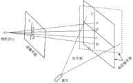
图3为本发明提供的激光线平面标定示意图。Fig. 3 is a schematic diagram of laser line plane calibration provided by the present invention.
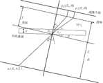
图4为本发明提供的光线追踪模型示意图。Fig. 4 is a schematic diagram of a ray tracing model provided by the present invention.
其中:1、电机;2、轴联器;3、黑白相机;4、532nm激光;5、彩色相机;6、固定板;7、丝杠;8、编码器;9、滑台。Among them: 1. Motor; 2. Coupling; 3. Black and white camera; 4. 532nm laser; 5. Color camera; 6. Fixed plate; 7. Lead screw; 8. Encoder; 9. Sliding table.
具体实施方式Detailed ways
下面对本发明的具体实施方式进行描述,以便于本技术领域的技术人员理解本发明,但应该清楚,本发明不限于具体实施方式的范围,对本技术领域的普通技术人员来讲,只要各种变化在所附的权利要求限定和确定的本发明的精神和范围内,这些变化是显而易见的,一切利用本发明构思的发明创造均在保护之列。The specific embodiments of the present invention are described below so that those skilled in the art can understand the present invention, but it should be clear that the present invention is not limited to the scope of the specific embodiments. For those of ordinary skill in the art, as long as various changes Within the spirit and scope of the present invention defined and determined by the appended claims, these changes are obvious, and all inventions and creations using the concept of the present invention are included in the protection list.
本发明实施例提供了一种水下混凝土表观激光线三维扫描测量方法,如图1所示,包括以下步骤The embodiment of the present invention provides a three-dimensional scanning measurement method of underwater concrete surface laser line, as shown in Figure 1, including the following steps
S1、对清水置换装置内的激光线扫描成像设备进行激光线平面标定,构建激光平面方程;S1. Calibrate the laser line plane of the laser line scan imaging equipment in the clean water replacement device, and construct the laser plane equation;
S2、建立光线在不同介质表面的光线追踪模型,进而建立真实像点与相机成像点之间的多介质折射模型;S2. Establish a ray tracing model of light on the surface of different media, and then establish a multi-media refraction model between the real image point and the camera imaging point;
S3、将多介质折射模型与相机成像模型融合,获得水下成像的归一化模型;S3. Merging the multi-media refraction model with the camera imaging model to obtain a normalized model for underwater imaging;
S4、利用归一化模型和激光平面方程将获取的水下混凝土表观激光线图像转换至对应空气中的激光线图像中,实现水下混凝土表观激光线三维扫描测量。S4. Using the normalized model and the laser plane equation, the obtained underwater concrete apparent laser line image is converted into the corresponding laser line image in the air, so as to realize the three-dimensional scanning measurement of the underwater concrete apparent laser line.
本发明实施例的步骤S1具体为:Step S1 of the embodiment of the present invention is specifically:
S11、将激光线扫描成像设备密封置于清水置换装置中;S11. Sealing the laser line scan imaging device in the water replacement device;
其中,清水置换装置为内含清水的玻璃块组成的密封结构,用于放置激光扫描成像设备,当水域水质浑浊影响激光扫描成像设备成像时,通过清水置换装置中的清水替换激光扫描成像设备中相机与被测物体间的浑浊水,以获取被测物体的清晰成像;Among them, the clear water replacement device is a sealed structure composed of glass blocks containing clear water, which is used to place the laser scanning imaging equipment. When the water quality in the water area is turbid and affects the imaging of the laser scanning imaging equipment, the clean water in the clear water replacement device replaces the laser scanning imaging equipment. The turbid water between the camera and the measured object to obtain a clear image of the measured object;
S12、利用激光线扫描成像设备扫描获取图像对相机参数进行标定;S12. Using a laser line scan imaging device to scan and obtain an image to calibrate the camera parameters;
S13、基于参数标定的相机,利用交比不变性对激光平面方程进行标定,构建激光平面方程。S13. Based on the parameter calibration camera, the laser plane equation is calibrated by using cross-ratio invariance, and the laser plane equation is constructed.
在本发明实施例中,激光线扫描成像设备结构如图2所示,包括电机、轴联器、黑白相机、彩色相机、532nm激光以及编码器;其中,532nm激光、黑白相机以及彩色相机均固定在固定板上,且532nm激光设置在黑白相机和彩色相机之间,固定板固定在滑台上,使相机与532nm激光能够在滑台上自由移动;具体地,滑台上设置有丝杠、编码器和轴联器,固定板设置在丝杠上,丝杠的一端与编码器连接,另一端通过轴联器与电机连接,轴联器在电机的转动下驱动固定板在丝杠上左右移动,并由编码器记录并反馈电机工作参数,进而控制电机工作以调整固定板的位置。In the embodiment of the present invention, the structure of the laser line scan imaging device is shown in Figure 2, including a motor, a coupling, a black and white camera, a color camera, a 532nm laser, and an encoder; wherein, the 532nm laser, the black and white camera, and the color camera are all fixed On the fixed plate, and the 532nm laser is set between the black-and-white camera and the color camera, the fixed plate is fixed on the slide table, so that the camera and the 532nm laser can move freely on the slide table; specifically, the slide table is provided with a screw, Encoder and shaft coupling, the fixed plate is set on the screw, one end of the screw is connected to the encoder, the other end is connected to the motor through the shaft coupling, and the shaft coupling drives the fixed plate to the left and right on the screw under the rotation of the motor Move, and the encoder records and feeds back the working parameters of the motor, and then controls the work of the motor to adjust the position of the fixed plate.
在本实施例的步骤S11中,基于上述激光线扫描成像设备的结构,其中激光线在相机(彩色相机和黑白相机)视场所成的像在视野正中央。In step S11 of this embodiment, based on the structure of the above-mentioned laser line scanning imaging device, the image formed by the laser line in the field of view of the camera (color camera and black and white camera) is in the center of the field of view.
在本实施例的步骤S11中,将上述激光线扫描成像设备密封在有机玻璃内部,并放置于清水置换装置中。In step S11 of this embodiment, the above-mentioned laser line scan imaging device is sealed inside the plexiglass and placed in a water replacement device.
在本实施例的步骤S13中,基于图3所示相机成像示意图,图中标定板指带棋盘格的标准板子,Li表示激光线在标定板上所呈现的直线条,li为Li在相机成像面上所呈现的直线段;得到在对激光线平面标定时的交比不变性的表达式为:In step S13 of this embodiment, based on the schematic diagram of camera imaging shown in FIG. 3 , the calibration board in the figure refers to a standard board with checkerboard grids,Li represents the straight line presented by the laser line on the calibration board, andli isLi The straight line segment presented on the imaging surface of the camera; the expression of the cross-ratio invariance when the laser line plane is calibrated is obtained as:

式中,


所述步骤S13中,对激光平面方程进行标定的方法为:In the step S13, the method for calibrating the laser plane equation is:
利用激光线与标定板的角点的交线确定Q点在图像坐标系中的坐标,利用交比不变性确定Q点在世界坐标系中的坐标,进而利用三张不同角度标定板与激光线交线确定三个不同的Q点,进而获得标定的激光线平面方程;Use the intersection line of the laser line and the corner point of the calibration plate to determine the coordinates ofthe Q point in the image coordinate system, use the cross-ratio invariance to determine the coordinates ofthe Q point in the world coordinate system, and then use three different angle calibration plates and laser lines The intersection line determines three differentQ points, and then obtains the calibrated laser line plane equation;

式中,A,B,C,D均为激光平面方程中的待定系数,x,y,z为平面任意的三维点。In the formula,A, B, C, and D are undetermined coefficients in the laser plane equation, andx, y, and z are arbitrary three-dimensional points on the plane.
由于清水置换装置能够消除水体浑浊对图像采集产生的影响,因此拍摄的激光线将不受水体环境对拍摄图像的影响。Since the clear water replacement device can eliminate the impact of water turbidity on image acquisition, the captured laser line will not be affected by the water environment on the captured image.
在本发明实施例中,由于光线在不同介质表面会产生折射现象,为此相机在空气中的成像模型不能准确的表达水下的真实成像情况,因此发明实施例中构建了用于水下成像的归一化模型,以消除折射畸变的影响,提升混凝土表观描精度。In the embodiment of the present invention, due to the refraction of light on the surface of different media, the imaging model of the camera in the air cannot accurately express the real imaging situation underwater. The normalized model is used to eliminate the influence of refraction distortion and improve the apparent drawing accuracy of concrete.
具体地,本发明实施的步骤S2采用snell定律建立光线在不同介质表面的光线追踪模型,利用光线追踪模型建立真实像点与相机成像点之间的多介质折射关系;其中,光线追踪模型的如图4所示,其表达式为:Specifically, step S2 implemented in the present invention adopts Snell's law to establish a ray tracing model of light on different medium surfaces, and uses the ray tracing model to establish the multi-media refraction relationship between the real image point and the camera imaging point; wherein, the ray tracing model is as follows: As shown in Figure 4, its expression is:


式中,


基于光线追踪模型构建的多介质折射模型的表达式为:The expression of the multi-medium refraction model based on the ray tracing model is:

在本实施例的步骤S3中,将多介质折射模型与相机成像模型融合,形成的水下成像的归一化模型;In step S3 of this embodiment, the multi-media refraction model is fused with the camera imaging model to form a normalized model for underwater imaging;
其中,对于没有介质折射时的相机成像模型为:Among them, the camera imaging model without medium refraction is:

式中,


多介质折射模型与相机成像模型融合的归一化模型的表达式为:The expression of the normalized model for the fusion of the multi-media refraction model and the camera imaging model is:

式中,


本发明实施例的步骤S4具体为:Step S4 of the embodiment of the present invention is specifically:
S41、利用完成参数标定的相机获取水下混凝土表观激光线图像;S41. Acquire the apparent laser line image of the underwater concrete by using the camera whose parameters have been calibrated;
S42、利用归一化模型对激光线图像中的像素坐标进行转换,获得消除畸变像素坐标的激光线图像;S42. Using the normalization model to convert the pixel coordinates in the laser line image to obtain the laser line image with the pixel coordinates of the distortion eliminated;
S43、对消除畸变像素坐标的激光线图像依次进行闭运算和骨架提取,获得无缺损激光线图像;S43. Perform closed operation and skeleton extraction on the laser line image with the pixel coordinates of the distortion eliminated in sequence to obtain a defect-free laser line image;
S44、利用灰度重心法对无缺损激光线图像提取激光线;S44. Using the gray-scale centroid method to extract laser lines from the defect-free laser line image;
S45、将提取的激光线中的像素点坐标带入激光平面方程,得到单列像素激光的三维坐标;S45. Bringing the pixel point coordinates in the extracted laser line into the laser plane equation to obtain the three-dimensional coordinates of the single-column pixel laser;
S46、将连续多帧激光线的三维坐标进行拼接,获得目标区域内水下混凝土的三维点云坐标,实现三维扫描测量。S46. Splicing the three-dimensional coordinates of the continuous multiple frames of laser lines to obtain the three-dimensional point cloud coordinates of the underwater concrete in the target area, so as to realize three-dimensional scanning measurement.
本发明中应用了具体实施例对本发明的原理及实施方式进行了阐述,以上实施例的说明只是用于帮助理解本发明的方法及其核心思想;同时,对于本领域的一般技术人员,依据本发明的思想,在具体实施方式及应用范围上均会有改变之处,综上所述,本说明书内容不应理解为对本发明的限制。In the present invention, specific examples have been applied to explain the principles and implementation methods of the present invention, and the descriptions of the above examples are only used to help understand the method of the present invention and its core idea; meanwhile, for those of ordinary skill in the art, according to this The idea of the invention will have changes in the specific implementation and scope of application. To sum up, the contents of this specification should not be construed as limiting the present invention.
本领域的普通技术人员将会意识到,这里所述的实施例是为了帮助读者理解本发明的原理,应被理解为本发明的保护范围并不局限于这样的特别陈述和实施例。本领域的普通技术人员可以根据本发明公开的这些技术启示做出各种不脱离本发明实质的其它各种具体变形和组合,这些变形和组合仍然在本发明的保护范围内。Those skilled in the art will appreciate that the embodiments described here are to help readers understand the principles of the present invention, and it should be understood that the protection scope of the present invention is not limited to such specific statements and embodiments. Those skilled in the art can make various other specific modifications and combinations based on the technical revelations disclosed in the present invention without departing from the essence of the present invention, and these modifications and combinations are still within the protection scope of the present invention.
Claims (8)


Priority Applications (1)
| Application Number | Priority Date | Filing Date | Title |
|---|---|---|---|
| CN202310527270.7ACN116242253B (en) | 2023-05-11 | 2023-05-11 | Underwater concrete apparent laser line three-dimensional scanning measurement method |
Applications Claiming Priority (1)
| Application Number | Priority Date | Filing Date | Title |
|---|---|---|---|
| CN202310527270.7ACN116242253B (en) | 2023-05-11 | 2023-05-11 | Underwater concrete apparent laser line three-dimensional scanning measurement method |
Publications (2)
| Publication Number | Publication Date |
|---|---|
| CN116242253Atrue CN116242253A (en) | 2023-06-09 |
| CN116242253B CN116242253B (en) | 2023-07-07 |
Family
ID=86631740
Family Applications (1)
| Application Number | Title | Priority Date | Filing Date |
|---|---|---|---|
| CN202310527270.7AExpired - Fee RelatedCN116242253B (en) | 2023-05-11 | 2023-05-11 | Underwater concrete apparent laser line three-dimensional scanning measurement method |
Country Status (1)
| Country | Link |
|---|---|
| CN (1) | CN116242253B (en) |
Cited By (1)
| Publication number | Priority date | Publication date | Assignee | Title |
|---|---|---|---|---|
| CN119313858A (en)* | 2024-10-22 | 2025-01-14 | 清华四川能源互联网研究院 | A 3D reconstruction system and method for underwater concrete defects |
Citations (13)
| Publication number | Priority date | Publication date | Assignee | Title |
|---|---|---|---|---|
| US20050254008A1 (en)* | 2002-06-14 | 2005-11-17 | Ferguson R D | Monitoring blood flow in the retina using a line-scanning laser ophthalmoscope |
| CN1825952A (en)* | 2006-03-21 | 2006-08-30 | 上海港务工程公司 | Full-operating mode underwater anode block welding image detecting system |
| CN2872304Y (en)* | 2006-03-21 | 2007-02-21 | 上海港务工程公司 | Totally work-condition anode block welding camer inspector underwater |
| US7408653B1 (en)* | 2006-01-27 | 2008-08-05 | The United States Of America As Represented By The Secretary Of The Army | Shim dialer platform and process to compensate for optical variations in components used in the assembly of seeker heads with folded optics for semi-active laser guided cannon launched projectiles |
| JP2014098602A (en)* | 2012-11-14 | 2014-05-29 | Hitachi Power Solutions Co Ltd | Underwater observation device, underwater observation method and radioactivity measurement method of fuel assembly using underwater observation method |
| CN105678742A (en)* | 2015-12-29 | 2016-06-15 | 哈尔滨工业大学深圳研究生院 | Underwater camera calibration method |
| CN110763152A (en)* | 2019-10-09 | 2020-02-07 | 哈尔滨工程大学 | Underwater active rotation structure light three-dimensional vision measuring device and measuring method |
| CN112509065A (en)* | 2020-12-28 | 2021-03-16 | 中国科学院合肥物质科学研究院 | Visual guidance method applied to deep sea mechanical arm operation |
| CN112991533A (en)* | 2021-03-18 | 2021-06-18 | 中国海洋大学 | Rotating underwater object three-dimensional reconstruction method based on laser triangulation |
| CN113435050A (en)* | 2021-06-30 | 2021-09-24 | 同济大学 | Multi-medium imaging analysis method for underwater medium surface position compensation |
| CN113744351A (en)* | 2021-09-03 | 2021-12-03 | 上海交通大学 | Underwater structured light measurement calibration method and system based on multi-medium refraction imaging |
| CN114357721A (en)* | 2021-12-09 | 2022-04-15 | 武汉华中天纬测控有限公司 | Underwater air imaging full-link simulation method |
| CN114964048A (en)* | 2021-09-30 | 2022-08-30 | 华北水利水电大学 | Underwater vision measuring device and measuring method based on ray refraction tracking |
- 2023
- 2023-05-11CNCN202310527270.7Apatent/CN116242253B/ennot_activeExpired - Fee Related
Patent Citations (13)
| Publication number | Priority date | Publication date | Assignee | Title |
|---|---|---|---|---|
| US20050254008A1 (en)* | 2002-06-14 | 2005-11-17 | Ferguson R D | Monitoring blood flow in the retina using a line-scanning laser ophthalmoscope |
| US7408653B1 (en)* | 2006-01-27 | 2008-08-05 | The United States Of America As Represented By The Secretary Of The Army | Shim dialer platform and process to compensate for optical variations in components used in the assembly of seeker heads with folded optics for semi-active laser guided cannon launched projectiles |
| CN1825952A (en)* | 2006-03-21 | 2006-08-30 | 上海港务工程公司 | Full-operating mode underwater anode block welding image detecting system |
| CN2872304Y (en)* | 2006-03-21 | 2007-02-21 | 上海港务工程公司 | Totally work-condition anode block welding camer inspector underwater |
| JP2014098602A (en)* | 2012-11-14 | 2014-05-29 | Hitachi Power Solutions Co Ltd | Underwater observation device, underwater observation method and radioactivity measurement method of fuel assembly using underwater observation method |
| CN105678742A (en)* | 2015-12-29 | 2016-06-15 | 哈尔滨工业大学深圳研究生院 | Underwater camera calibration method |
| CN110763152A (en)* | 2019-10-09 | 2020-02-07 | 哈尔滨工程大学 | Underwater active rotation structure light three-dimensional vision measuring device and measuring method |
| CN112509065A (en)* | 2020-12-28 | 2021-03-16 | 中国科学院合肥物质科学研究院 | Visual guidance method applied to deep sea mechanical arm operation |
| CN112991533A (en)* | 2021-03-18 | 2021-06-18 | 中国海洋大学 | Rotating underwater object three-dimensional reconstruction method based on laser triangulation |
| CN113435050A (en)* | 2021-06-30 | 2021-09-24 | 同济大学 | Multi-medium imaging analysis method for underwater medium surface position compensation |
| CN113744351A (en)* | 2021-09-03 | 2021-12-03 | 上海交通大学 | Underwater structured light measurement calibration method and system based on multi-medium refraction imaging |
| CN114964048A (en)* | 2021-09-30 | 2022-08-30 | 华北水利水电大学 | Underwater vision measuring device and measuring method based on ray refraction tracking |
| CN114357721A (en)* | 2021-12-09 | 2022-04-15 | 武汉华中天纬测控有限公司 | Underwater air imaging full-link simulation method |
Non-Patent Citations (4)
| Title |
|---|
| 何露茜;何斌;: "一种基于多相机的多介质三维重建算法研究", 数字技术与应用, no. 02* |
| 张洪龙;陈涛;庄培钦;周志盛;宋展;焦国华;乔宇;: "基于立体视觉的水下三维测量系统研究", 集成技术, no. 03* |
| 管风;韩宏伟;张晓晖;: "水下目标激光成像的可视化模型", 中国激光, no. 05* |
| 谢亮亮;屠大维;张旭;肖国梁;金攀;: "深海原位激光扫描双目立体视觉成像系统", 仪器仪表学报, no. 06* |
Cited By (1)
| Publication number | Priority date | Publication date | Assignee | Title |
|---|---|---|---|---|
| CN119313858A (en)* | 2024-10-22 | 2025-01-14 | 清华四川能源互联网研究院 | A 3D reconstruction system and method for underwater concrete defects |
Also Published As
| Publication number | Publication date |
|---|---|
| CN116242253B (en) | 2023-07-07 |
Similar Documents
| Publication | Publication Date | Title |
|---|---|---|
| CN109544679B (en) | Three-dimensional reconstruction method for inner wall of pipeline | |
| CN105678742B (en) | A kind of underwater camera scaling method | |
| CN112540089B (en) | Application method of digital imaging system in concrete bridge crack detection and analysis | |
| CN105092607B (en) | Spherical optics element surface flaw evaluation method | |
| CN110763152A (en) | Underwater active rotation structure light three-dimensional vision measuring device and measuring method | |
| CN105547189A (en) | Mutative scale-based high-precision optical three-dimensional measurement method | |
| CN115187565A (en) | A kind of underwater bridge pier disease identification and positioning method, device, electronic equipment and storage medium | |
| CN115471777A (en) | Refined water flow velocity field acquisition method and system based on video identification | |
| CN102749046A (en) | Method for measuring shearing area of rock structral plane in direct shear test | |
| CN116242253A (en) | Underwater concrete apparent laser line three-dimensional scanning measurement method | |
| CN103793909B (en) | Single vision global depth information getting method based on diffraction blurring | |
| CN114494134A (en) | Industrial defect detection system based on component point cloud registration detection | |
| CN114964048A (en) | Underwater vision measuring device and measuring method based on ray refraction tracking | |
| CN114663382A (en) | Surface defect detection method for electronic component based on YOLOv5 convolutional neural network | |
| CN113222937A (en) | Detection method and detection device for appearance peripheral surface defects of nuclear fuel pellet | |
| CN117197010A (en) | Method and device for carrying out workpiece point cloud fusion in laser cladding processing | |
| CN116824079A (en) | Three-dimensional entity model construction method and device based on full-information photogrammetry | |
| CN116862856A (en) | Concrete dam surface crack detection system and method based on improved YOLOv5 model | |
| CN107977938A (en) | A Kinect Depth Image Restoration Method Based on Light Field | |
| CN118654601A (en) | A method for detecting verticality of prestressed concrete T-beam bridge piers by using drone photography | |
| CN103985121A (en) | A method for calibrating an underwater projector | |
| Yu et al. | Nuclear containment damage detection and visualization positioning based on YOLOv5m-FFC | |
| CN115272067A (en) | Laser radar three-dimensional range profile super-resolution reconstruction method based on neural network | |
| CN112767249B (en) | Image unfolding and splicing method and system for surface defect detection of small pipe fitting | |
| CN119269349A (en) | A method for monitoring sediment characteristics of sand-laden water flow based on image recognition |
Legal Events
| Date | Code | Title | Description |
|---|---|---|---|
| PB01 | Publication | ||
| PB01 | Publication | ||
| SE01 | Entry into force of request for substantive examination | ||
| SE01 | Entry into force of request for substantive examination | ||
| GR01 | Patent grant | ||
| GR01 | Patent grant | ||
| CF01 | Termination of patent right due to non-payment of annual fee | Granted publication date:20230707 | |
| CF01 | Termination of patent right due to non-payment of annual fee |