CN116241196A - Cable throwing and fishing wet joint, cable intelligent separate injection system and construction method thereof - Google Patents
Cable throwing and fishing wet joint, cable intelligent separate injection system and construction method thereofDownload PDFInfo
- Publication number
- CN116241196A CN116241196ACN202310301638.8ACN202310301638ACN116241196ACN 116241196 ACN116241196 ACN 116241196ACN 202310301638 ACN202310301638 ACN 202310301638ACN 116241196 ACN116241196 ACN 116241196A
- Authority
- CN
- China
- Prior art keywords
- cable
- wet joint
- head
- female
- male
- Prior art date
- Legal status (The legal status is an assumption and is not a legal conclusion. Google has not performed a legal analysis and makes no representation as to the accuracy of the status listed.)
- Granted
Links
Images
Classifications
- E—FIXED CONSTRUCTIONS
- E21—EARTH OR ROCK DRILLING; MINING
- E21B—EARTH OR ROCK DRILLING; OBTAINING OIL, GAS, WATER, SOLUBLE OR MELTABLE MATERIALS OR A SLURRY OF MINERALS FROM WELLS
- E21B17/00—Drilling rods or pipes; Flexible drill strings; Kellies; Drill collars; Sucker rods; Cables; Casings; Tubings
- E21B17/02—Couplings; joints
- E21B17/08—Casing joints
- E—FIXED CONSTRUCTIONS
- E21—EARTH OR ROCK DRILLING; MINING
- E21B—EARTH OR ROCK DRILLING; OBTAINING OIL, GAS, WATER, SOLUBLE OR MELTABLE MATERIALS OR A SLURRY OF MINERALS FROM WELLS
- E21B41/00—Equipment or details not covered by groups E21B15/00 - E21B40/00
- E—FIXED CONSTRUCTIONS
- E21—EARTH OR ROCK DRILLING; MINING
- E21B—EARTH OR ROCK DRILLING; OBTAINING OIL, GAS, WATER, SOLUBLE OR MELTABLE MATERIALS OR A SLURRY OF MINERALS FROM WELLS
- E21B43/00—Methods or apparatus for obtaining oil, gas, water, soluble or meltable materials or a slurry of minerals from wells
- E21B43/16—Enhanced recovery methods for obtaining hydrocarbons
- E21B43/20—Displacing by water
Landscapes
- Engineering & Computer Science (AREA)
- Life Sciences & Earth Sciences (AREA)
- Geology (AREA)
- Mining & Mineral Resources (AREA)
- Physics & Mathematics (AREA)
- Environmental & Geological Engineering (AREA)
- Fluid Mechanics (AREA)
- General Life Sciences & Earth Sciences (AREA)
- Geochemistry & Mineralogy (AREA)
- Mechanical Engineering (AREA)
- Quick-Acting Or Multi-Walled Pipe Joints (AREA)
Abstract
Translated fromChinese
Description
Translated fromChinese技术领域technical field
本发明属于油田智能分层注水技术领域,涉及一种可适用于带压作业分注系统,具体指一种电缆投捞湿接头、有缆智能分注系统及其施工方法。The invention belongs to the technical field of intelligent layered water injection in oilfields, and relates to a distribution injection system applicable to pressurized operations, in particular to a cable throwing and fishing wet joint, a cable intelligent distribution injection system and a construction method thereof.
背景技术Background technique
精细化的智能分层注水技术对油田提高采收率起到很大作用,随着技术不断进步,油田在分层注水领域的工艺方法不断更新。目前在逐步推广井下长期放置的智能分注工艺技术,按照通信方式主要分为传统有缆式智能分注技术和波码式智能分注技术。The refined intelligent layered water injection technology has played a great role in improving oil recovery. With the continuous advancement of technology, the oilfield's technology in the field of layered water injection has been continuously updated. At present, the intelligent dispensing technology that has been placed underground for a long time is being gradually promoted. According to the communication method, it is mainly divided into traditional cable-type intelligent dispensing technology and wave code-type intelligent dispensing technology.
然而在实际应用过程中,这两种分注技术均存在一定优势和局限性,传统有缆智能分注技术数据传输和控制的时效性高,但管柱结构工具段和油管段均需要使用大量电缆护卡在油管外固定电缆,耗时费力,电缆密封点多,且无法实现带压作业;波码式智能分注技术管柱结构工具段和油管段没有外绑电缆,可以实现带压作业,但其通过压力波或流量波收发数据,一条指令或数据通信耗时往往需要数十分钟,时效性差,效率低下,且无法实时获取井下仪器状态,施工选井对井况有一定要求。However, in the actual application process, these two separate injection technologies have certain advantages and limitations. The traditional cabled intelligent separate injection technology has high timeliness in data transmission and control, but both the string structure tool section and the tubing section need to use a large number of The cable guard is used to fix the cable outside the oil pipe, which is time-consuming and labor-intensive. There are many sealing points for the cable, and it is impossible to realize the under pressure operation; the wave code intelligent separation technology pipe string structure tool section and the oil pipe section have no external cables, which can realize the under pressure operation , but it transmits and receives data through pressure waves or flow waves. A command or data communication often takes tens of minutes, which is poor in timeliness and efficiency, and it is impossible to obtain the status of downhole instruments in real time. Construction well selection has certain requirements for well conditions.
发明内容Contents of the invention
为了解决上述问题,本发明提供一种适用于有缆智能分注的电缆投捞湿接头、系统和方法,其通过电缆投捞湿接头将电缆内置与油管内部,不需要外部固定电缆,即实现了带压作业又可以对井下仪器状态进行实时监测,时效性好,效率高。In order to solve the above problems, the present invention provides a cable fishing wet joint, system and method suitable for cable intelligent dispensing. The cable is built into the inside of the oil pipe through the cable fishing wet joint, and no external fixing of the cable is required. In addition to the snubbing operation, the downhole instrument status can be monitored in real time, with good timeliness and high efficiency.
为了实现上述目的,本发明采用的技术方案如下:In order to achieve the above object, the technical scheme adopted in the present invention is as follows:
一种电缆投捞湿接头母头,包括柱套,所述柱套的上、下端均设置有端盖,所述的柱套内套设有环套,所述环套与所述的柱套下端的端盖连接,所述的环套和柱套之间形成环形过流通道,所述环套的内周面上套设有母头导电环,所述母头导电环的上、下端部均设置有套设在所述环套内周面的母头绝缘套,所述一对母头绝缘套相对的两个外端端部还设置有套设在所述环套内周面的母头密封环,所述的柱套上端的端盖内周面径向分布设置有若干与所述环形过流通道贯通的第一液孔,所述柱套下端的端盖内周面径向分布设置有若干与所述环形过流通道贯通的第二液孔。A female head of a cable fishing wet joint, including a column sleeve, the upper and lower ends of the column sleeve are provided with end caps, the inner sleeve of the column sleeve is provided with a ring sleeve, and the ring sleeve and the column sleeve The end cap at the lower end is connected, and an annular flow passage is formed between the ring sleeve and the column sleeve. A female conductive ring is sleeved on the inner peripheral surface of the ring sleeve, and the upper and lower ends of the female conductive ring Both are provided with female head insulating sleeves sleeved on the inner peripheral surface of the ring sleeve, and the two opposite outer ends of the pair of female head insulating sleeves are also provided with female head insulating sleeves sleeved on the inner peripheral surface of the ring sleeve. The head sealing ring, the inner peripheral surface of the end cap at the upper end of the column sleeve is radially distributed with a number of first liquid holes that communicate with the annular flow channel, and the inner peripheral surface of the end cap at the lower end of the column sleeve is radially distributed. A plurality of second liquid holes communicating with the annular flow channel are provided.
进一步,还包括母头电缆,所述母头电缆的一端连接在所述的母头导电环上,母头电缆的另一端沿所述的环套向下延伸至所述柱套下端的端盖端部。Further, a female cable is also included, one end of the female cable is connected to the female conductive ring, and the other end of the female cable extends downward along the ring sleeve to the end cap at the lower end of the column sleeve Ends.
一种电缆投捞湿接头,包括上述的湿接头母头,所述的湿接母头内插设有湿接头公头,所述的湿接头公头包括电缆头柱,所述电缆头柱的外周面套设有与母头导电环接触导通的公头导电环,所述公头导电环的上、下端部均设置有套设在所述电缆头柱外周面的公头绝缘套,所述一对公头绝缘套相对的两个外端端部还设置有套设在所述电缆头柱外周面的公头密封圈,所述电缆头柱的下端具有绝缘油容纳腔,所述绝缘油容纳腔的内部从上到下依次设置有绝缘油单向阀、弹簧和差压滑轴,所述绝缘油单向阀上端的绝缘油容纳腔的径向设置有若干贯穿电缆头柱外周面的第三液孔,差压滑轴下端的绝缘油容纳腔的径向设置有若干贯穿电缆头柱外周面的第四液孔,所述用于填充的绝缘油由第四液孔进入使所述差压滑轴上移触动所述的弹簧开启绝缘油单向阀后从第三液孔流出。A cable fishing wet joint, including the above-mentioned wet joint female head, the wet joint male head is inserted in the wet joint female head, the wet joint male head includes a cable head column, and the cable head column The outer peripheral surface is covered with a male conductive ring that is in contact with the female conductive ring, and the upper and lower ends of the male conductive ring are provided with a male insulating sleeve that is sleeved on the outer peripheral surface of the cable stud. The two opposite outer ends of the pair of male insulating sleeves are also provided with male sealing rings sleeved on the outer peripheral surface of the cable stud, the lower end of the cable stud has an insulating oil containing cavity, and the insulating An insulating oil check valve, a spring, and a differential pressure sliding shaft are arranged in the oil receiving chamber in sequence from top to bottom, and a number of holes are arranged in the radial direction of the insulating oil receiving chamber at the upper end of the insulating oil check valve through the outer peripheral surface of the cable head column. The third liquid hole of the differential pressure sliding shaft is radially provided with a number of fourth liquid holes penetrating through the outer peripheral surface of the cable head post in the radial direction of the insulating oil chamber at the lower end of the differential pressure sliding shaft. The insulating oil used for filling enters through the fourth liquid hole so that all The differential pressure sliding shaft moves upward to touch the spring to open the insulating oil check valve and then flows out from the third liquid hole.
进一步,所述的湿接头公头还包括公头电缆,所述公头电缆的插设在所述的电缆头柱内,公头电缆一端向上延伸出所述的电缆头柱上端部,公头电缆的另一端沿所述的电缆头柱向下延伸与所述的公头导电环相接。Further, the male head of the wet joint also includes a male cable, the male cable is inserted into the cable head column, and one end of the male cable extends upwards from the upper end of the cable head column, and the male cable The other end of the cable extends downward along the cable stud and connects with the male conductive ring.
进一步,所述湿接头公头插接在所述湿接头母头内时,所述的公头导电环和母头导电环相互密封绝缘导通;所述湿接头公头脱离所述的湿接头母头时,所述湿接头母头的中心通道形成用于下放测井仪器的通道。Further, when the wet joint male is plugged into the wet joint female, the male conductive ring and the female conductive ring are sealed and insulated from each other; the wet joint male is separated from the wet joint When the female head is used, the central channel of the female head of the wet joint forms a channel for lowering the logging instrument.
进一步,所述的湿接头公头还包括配重块,所述的配重块连接在所述绝缘油容纳腔下端。Further, the wet joint male head further includes a counterweight, and the counterweight is connected to the lower end of the insulating oil containing chamber.
进一步,所述的湿接头公头上设置有锁定结构,所述的锁定结构包括设置在所述湿接头公头的电缆头柱外周面的锁定块和锁定销,所述锁定块被所述锁定销限位时所述湿接头公头和所述湿接头母头上端锁合连接,所述的锁定销断开时,所述的湿接头公头和湿接头母头脱离。Further, the wet joint male is provided with a locking structure, the locking structure includes a locking block and a locking pin arranged on the outer peripheral surface of the cable stud of the wet joint male, and the locking block is locked by the When the pin is limited, the upper ends of the wet joint male head and the wet joint female head are locked and connected, and when the locking pin is disconnected, the wet joint male head and the wet joint female head are disengaged.
一种有缆智能分注系统,包括上述的电缆投捞湿接头、地面控制器和工具段,所述工具段的外部套设有地下套管,所述的电缆投捞湿接头套设在所述地下套管内的工具段上端,所述工具段通过所述电缆投捞湿接头与所述地面控制器连接。A cable intelligent dispensing system, comprising the above-mentioned cable fishing wet joint, a ground controller and a tool section, the outside of the tool section is covered with an underground casing, and the cable fishing wet joint is sleeved The upper end of the tool section in the underground casing, the tool section is connected to the ground controller through the cable fishing wet joint.
进一步,所述电缆投捞湿接头的湿接头公头套设在地下套管的油管内,所述湿接头公头的上端通过地面电缆接入所述的地面控制器,所述湿接头母头连接所述的工具段;所述的工具段包括智能分注仪,所述的智能分注仪通过油管与所述的湿接头母头连接,所述的油管内设置钢管电缆,所述钢管电缆上端接入所述电缆投捞湿接头的下端与所述的母头电缆连接,钢管电缆下端连接所述的智能分注仪;所述的地面电缆下端与所述湿接头公头上端的公头电缆端部连接。Further, the wet joint male head of the cable fishing wet joint is set in the oil pipe of the underground casing, the upper end of the wet joint male head is connected to the ground controller through the ground cable, and the wet joint female head is connected to The tool section; the tool section includes an intelligent dispensing instrument, the intelligent dispensing instrument is connected to the female head of the wet joint through an oil pipe, a steel pipe cable is arranged in the oil pipe, and the upper end of the steel pipe cable The lower end of the wet joint connected to the cable is connected to the female cable, and the lower end of the steel pipe cable is connected to the intelligent dispensing instrument; the lower end of the ground cable is connected to the male cable at the upper end of the wet joint. end connections.
一种有缆智能分注系统的施工方法,包括下述步骤:A construction method for a cable intelligent dispensing system, comprising the following steps:
步骤S1,从分注井井口依次下入工具段,工具段的钢管电缆从油管内部穿过,钢管电缆从最下层的智能分注仪一直连接到工具段最上端的湿接头母头下端;Step S1, lowering the tool section sequentially from the wellhead of the injection well, the steel pipe cable of the tool section passes through the oil pipe, and the steel pipe cable is connected from the intelligent dispensing instrument at the bottom to the lower end of the wet joint female head at the top of the tool section;
步骤S2,工具段上端连接湿接头母头,湿接头母头连接油管一直到井口,完成管柱施工;Step S2, the upper end of the tool section is connected to the female head of the wet joint, and the female head of the wet joint is connected to the tubing all the way to the wellhead to complete the string construction;
步骤S3,进行井口施工和地面控制器安装施工;Step S3, carrying out wellhead construction and ground controller installation and construction;
步骤S4,地面控制器通过地面电缆挂接湿接头公头,使湿接头公头入井与湿接头母头对接;In step S4, the ground controller connects the wet joint male head with the ground cable, so that the wet joint male head enters the well and connects with the wet joint female head;
步骤S5,通过湿接头公头提出工具段后,通过湿接头母头的中心通道下放传统测试仪器进行测井。In step S5, after the tool section is lifted out through the male wet joint, the traditional testing instrument is lowered through the central channel of the wet joint female for well logging.
本发明由于采取以上技术方案,其具有以下优点和效果:The present invention has the following advantages and effects due to the adoption of the above technical scheme:
1、本发明的智能分注系统,工具段内连接有缆式电动测封一体化智能分注仪,工具段上方连接电缆投捞湿接头,工具段和湿接头公头到井口的油管段均没有外露电缆,电缆从油管内部连接湿接头公头,使用电缆投捞湿接头公头下放对接湿接头母头,无需绑电缆护卡,避免了下地下套管时损伤电缆,施工效率高,由于带缆施工可支持带压作业,无井液溢流到地面,避免前期注入到地层内部的水反吐,井口作业对环境友好,有利于环保。1. In the intelligent dispensing system of the present invention, the tool section is connected with a cable-type electric measuring and sealing integrated intelligent dispensing instrument, and the upper part of the tool section is connected with a cable to cast and fish the wet joint. There is no exposed cable, the cable is connected to the male head of the wet joint from the inside of the oil pipe, and the male head of the wet joint is lowered to connect with the female head of the wet joint by using the cable, without the need to bind the cable guard card, which avoids damage to the cable when the underground casing is lowered, and the construction efficiency is high. The cable construction can support the operation under pressure, no well fluid overflows to the ground, and avoids the water injected into the formation in the early stage from regurgitation. The wellhead operation is environmentally friendly and conducive to environmental protection.
2、本发明的电缆投捞湿接头的湿接头母头连接在工具段最上端,湿接头母头与湿接头公头对接后可与湿接头公头一起实现电缆与井下有缆式电动测封一体化智能分注仪之间的电气连接与密封绝缘,湿接头母头内部的环形过流通道用于过液,当湿接头公头上提后脱离湿接头母头后,湿接头母头中心用于插接湿接头公头的中心通道又可作为测试仪器的通道使用,使得下分层流量、温度、压力及水嘴开度的可以实时进行监测,数据实时读取,测调效率高。2. The wet joint female head of the cable fishing wet joint of the present invention is connected to the uppermost end of the tool section. After the wet joint female head is docked with the wet joint male head, it can be used together with the wet joint male head to realize the electric sealing of the cable and the downhole cable The electrical connection and sealing insulation between the integrated intelligent dispensing devices, the annular overflow channel inside the wet joint female head is used for liquid flow, when the wet joint male head is lifted up and separated from the wet joint female head, the center of the wet joint female head The central channel for plugging the wet joint male head can also be used as the channel of the test instrument, so that the flow rate, temperature, pressure and nozzle opening of the lower layer can be monitored in real time, the data can be read in real time, and the measurement and adjustment efficiency is high.
3、本发明的电缆投捞湿接头单次对接具备二次注油功能,提高绝缘性能的可靠性,绝缘时只需通过自动注油机构排出电缆投捞湿接头内导电腔体内残留水渍,填充绝缘油,实现机构的绝缘效果,并且电缆投捞湿接头的公头和母头可以不限次数对接,每次对接前将绝缘油进行补充,保障绝缘性能一致,保证多次对接的重复一致性。3. The single docking of the cable fishing wet joint has the function of secondary oil injection, which improves the reliability of the insulation performance. When insulating, it only needs to discharge the residual water stains in the conductive cavity of the cable fishing wet joint through the automatic oil injection mechanism, and fill the insulation Oil, to achieve the insulation effect of the mechanism, and the male and female connectors of the cable fishing wet joint can be docked for an unlimited number of times. Before each docking, the insulating oil is replenished to ensure consistent insulation performance and repeat consistency for multiple dockings.
附图说明Description of drawings
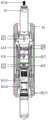
图1为本发明电缆投捞湿接头公头结构示意图。Fig. 1 is a schematic diagram of the structure of the male head of the cable fishing wet joint according to the present invention.
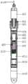
图2为本发明电缆投捞湿接头母头结构示意图。Fig. 2 is a schematic diagram of the structure of the female head of the cable fishing wet joint according to the present invention.
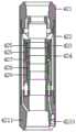
图3为本发明电缆投捞湿接头公头和母头插接配合结构示意图。Fig. 3 is a schematic diagram of the plug-fit structure of the male and female plugs of the wet connector for cable throwing and fishing according to the present invention.
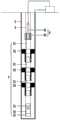
图4为本发明有缆智能分注系统结构示意图。Fig. 4 is a schematic structural diagram of the wired intelligent dispensing system of the present invention.
其中,1-地面控制器,2-地下套管,3-油管,4-电缆投捞湿接头,5-工具段;Among them, 1-ground controller, 2-underground casing, 3-oil pipe, 4-cable fishing wet joint, 5-tool section;
41-湿接头公头,411-电缆头柱,412-锁定销,413-锁定块,414-公头上密封圈,415-公头上绝缘套,416-公头导电环,417-公头下绝缘套,418-公头下密封圈,419-绝缘油单向阀,4110-弹簧,4111-绝缘油容纳腔,4112-差压滑轴,4113-配重块,4114-公头电缆;41-wet joint male, 411-cable stud, 412-locking pin, 413-locking block, 414-male seal ring, 415-male insulation sleeve, 416-male conductive ring, 417-male Lower insulating sleeve, 418-male lower sealing ring, 419-insulating oil check valve, 4110-spring, 4111-insulating oil chamber, 4112-differential pressure sliding shaft, 4113-counterweight, 4114-male cable;
42-湿接头母头,421-上端盖,422-柱套,423-环套,424-环形过流通道,425-母头上密封环,426-母头上绝缘套,427-母头导电环,428-母头下绝缘套,429-母头下密封环,4210-母头电缆,4211-下端盖;42-female head of wet joint, 421-upper end cap, 422-column sleeve, 423-ring sleeve, 424-annular overcurrent channel, 425-seal ring on female head, 426-insulating sleeve on female head, 427-female head conductive Ring, 428-female lower insulating sleeve, 429-female lower sealing ring, 4210-female cable, 4211-lower end cover;
51-钢管电缆,52-智能分注仪,53-双作用凡尔,54-筛管,55-丝堵。51-Steel pipe cable, 52-Intelligent dispensing instrument, 53-Double action valve, 54-Screen tube, 55-Silk plug.
具体实施方式Detailed ways
以下将结合附图对本发明的实施例进行详细说明,以便更清楚理解本发明的目的、特点和优点。应理解的是,附图所示的实施例并不是对本发明范围的限制,而只是为了说明本发明技术方案的实质精神。Embodiments of the present invention will be described in detail below with reference to the accompanying drawings, so as to better understand the purpose, features and advantages of the present invention. It should be understood that the embodiments shown in the drawings are not intended to limit the scope of the present invention, but only to illustrate the essence of the technical solutions of the present invention.
本发明的一种电缆投捞湿接头及有缆智能分注系统和施工方法。一种电缆投捞湿接头包括电缆投捞湿接母头和电缆投捞湿接公头,电缆投捞湿接公头插接在所述电缆投捞湿接母头内形成密封连接可以井下工具段进行连接,拔出电缆投捞湿接公头后,电缆投捞湿接母头可单独使用。本发明的有缆智能分注系统可适合带压作业,包括地面控制器、电缆投捞湿接头和工具段,工具段包括有缆式电动测封一体化智能分注仪,工具段上方连接电缆投捞湿接头母头,湿接头母头与湿接头公头对接并一起实现电缆与井下有缆式智能分注仪之间的电气连接与密封绝缘,湿接头公头拔出后,湿接头母头的中心通道可作为测试仪器通道使用,由于没有外露电缆,避免了下地下套管时损伤电缆,因此可以实现带压作业,同时可以实时监测井下数据。The present invention relates to a cable throwing and fishing wet joint, a cable intelligent distributing system and a construction method. A cable throwing wet joint includes a cable throwing wet joint female head and a cable throwing wet joint male head. After the cable is pulled out and the wet connector is pulled out, the cable connector can be used separately. The cable intelligent dispensing system of the present invention is suitable for working under pressure, and includes a ground controller, a cable fishing wet joint and a tool section. Throw in the wet joint female head, the wet joint female head and the wet joint male head are docked together to realize the electrical connection and sealing insulation between the cable and the downhole cable-type intelligent dispensing instrument. After the wet joint male head is pulled out, the wet joint female head The central channel of the head can be used as a test instrument channel. Since there is no exposed cable, it avoids damage to the cable when running the underground casing, so it can realize the operation under pressure and monitor the downhole data in real time.
如图1、图2、图3所示。本发明提供的一种电缆投捞湿接头,包括湿接头母头42和湿接头公头41。湿接头公头41和插入所述的湿接头母头42实现密封,拔出湿接头公头41后,湿接头母头42中心内腔作为下方管柱的通道使用。所述湿接头母头42包括柱套422和母头电缆4210,所述柱套422的上、下端均设置有端盖,所述的柱套422内套设有环套423,所述环套423与所述的柱套422下端的端盖连接,所述的环套423和柱套422之间形成环形过流通道424,所述环套423的内周面上套设有母头导电环427,所述母头导电环427的上、下端部均设置有套设在所述环套423内周面的母头绝缘套,所述一对母头绝缘套相对的两个外端端部还设置有套设在所述环套423内周面的母头密封环,所述的柱套422上端的端盖内周面径向分布设置有若干与所述环形过流通道424贯通的第一液孔,所述柱套422下端的端盖内周面径向分布设置有若干与所述环形过流通道424贯通的第二液孔。所述母头电缆4210的一端连接在所述的母头导电环427上,母头电缆4210的另一端沿所述的环套423向下延伸至所述柱套422下端的端盖端部。As shown in Figure 1, Figure 2, and Figure 3. A cable fishing wet joint provided by the present invention includes a wet joint female 42 and a wet
具体的说,湿接头母头42为圆形管体结构,内部上下端贯通形成中心通道。湿接头母头42下端可与工具段油管连接。柱套422为环形筒体,上下端设置有环形口槽。所述的端盖包括上端盖421和下端盖4211,上端盖421和下端盖4211端部设置台阶面与柱套422上下端环形口槽匹配。柱套422和上端盖421和下端盖4211密封连接螺母或过盈配合。上端盖421内腔成锥形腔体便于液体流入和湿接头公头41插入,上端盖421沿所述的内腔壁上开设若干径向分布的第一液孔,第一液孔沿上端盖421内腔壁轴向贯通将上端盖421的内腔与过流通道424上端贯通。下端盖4211内腔成锥形腔体便于液体流出,下端盖4211沿所述的内腔壁上开设若干径向分布的第二液孔,第一液孔沿下端盖4211内腔壁轴向贯通将下端盖4211的内腔与过流通道424下端贯通。第一液孔、第二液孔和过流通道424连通形成注水通道。当湿接头母头42的中心通道内插入湿接头公头41时,注水通道可作为替代中心通道的注水通道。Specifically, the wet joint
所述的环套423也为环形筒体,环套423下端套壁内轴向设置有容纳母头电缆4210第一电缆通道,第一电缆通道上端贯通套壁后与母头导电环427相通,母头电缆4210上端沿第一电缆通道延伸至母头导电环427与其连接。在下端盖4211的内壁内设置轴向的第二电缆通道与环套423上的第一电缆通道贯通,第二电缆通道贯通下端盖4211的上下端面。母头电缆4210的下端部沿第二电缆通道延伸至下端盖4211的端部。所述母头密封环包括母头上密封环425和母头下密封环429,母头绝缘套包括母头上绝缘套426和母头下绝缘套428,母头上绝缘套426和母头下绝缘套428设置在母头导电环427两端实现母头导电环427的绝缘,母头上密封环425和母头下密封环429分别设置在母头上绝缘套426和母头下绝缘套428两端实现母头导电环427的密封。The
进一步,所述的湿接头公头41包括电缆头柱411和公头电缆4114,所述电缆头柱411的外周面套设有与母头导电环427接触导通的公头导电环416,所述公头导电环416的上、下端部均设置有套设在所述电缆头柱411外周面的公头绝缘套,所述一对公头绝缘套相对的两个外端端部还设置有套设在所述电缆头柱411外周面的公头密封圈,所述电缆头柱411的下端具有绝缘油容纳腔4111,所述绝缘油容纳腔4111的内部从上到下依次设置有绝缘油单向阀419、弹簧4110和差压滑轴4112,绝缘油单向阀419上端的绝缘油容纳腔4111的径向设置有若干贯穿电缆头柱411外周面的第三液孔,差压滑轴4112下端的绝缘油容纳腔4111的径向设置有若干贯穿电缆头柱411外周面的第四液孔,所述用于填充的绝缘油由第四液孔进入所述绝缘油容纳腔4111的下部内推动所述差压滑轴4112上移触动所述弹簧4110挤压开启绝缘油单向阀419后从第三液孔流出。所述公头电缆4114插设在所述的电缆头柱411内,所述公头电缆4114的一端向上延伸出所述的电缆头柱411上端部,公头电缆4114的另一端沿所述的电缆头柱411向下延伸与所述的公头导电环416相接。Further, the
具体的说,电缆头柱411为圆柱体结构,电缆头柱411上端内部中心开设有第三电缆通道,第三电缆通道沿电缆头柱411轴向延伸至公头导电环416的内环面,第三电缆通道下端径向贯穿电缆头柱411后与公头导电环416相对,公头电缆4114通过第三电缆通道连接至公头导电环416。公头密封圈包括公头上密封圈414和公头下密封圈418,公头绝缘套包括公头上绝缘套415和公头下绝缘套417,公头上绝缘套415和公头下绝缘套417设置在公头导电环416两端实现公头导电环416的绝缘,公头上密封圈414和公头下密封圈418分别设置在公头上绝缘套415和公头下绝缘套417两端实现公头导电环416的密封。湿接头公头41和湿接头母头42相互插接配合时,公头导电环416和母头导电环427实现密封绝缘导通。第三液孔和第四液孔形成绝缘油的环形导通使绝缘油单向阀419实现开闭。Specifically, the
进一步,所述湿接头公头41插接在所述湿接头母头42内时,所述的公头导电环416和母头导电环427相互密封绝缘导通;所述湿接头公头41脱离所述的湿接头母头42时,所述湿接头母头42的中心通道形成用于下放测井仪器的通道。所述湿接头公头41和湿接头母头42相互插接配合时,所述的公头导电环416和母头导电环427相互实现贴合导通,此时一对公头绝缘套和一对母头绝缘套相互贴合将所述的公头导电环416和母头导电环427的两端绝缘,一对公头密封圈和一对外部密封圈相互贴合将所述一对母头绝缘套和公头绝缘套的两端密封。Further, when the wet joint male 41 is plugged into the wet joint female 42, the male
具体的说,湿接头公头41插入所述的湿接头母头42时,湿接头公头41负责与湿接头母头42对接,湿接头公头41与湿接头母头42对接后一起实现电缆与井下有缆式电动测封一体化智能分注仪52之间的电气连接与密封绝缘。湿接头公头41和湿接头母头42对接密封后,上下密封面之间形成空腔导电腔体同时,可以防止导电腔体内的绝缘油和油管内的注水液发生内外液体交换。Specifically, when the wet joint male 41 is inserted into the wet joint female 42, the wet joint male 41 is responsible for docking with the wet joint female 42, and the wet joint male 41 and the wet joint female 42 are docked together to realize the cable Electrical connection and sealing insulation with the downhole cable type electric sealing integrated
所述的湿接头公头41和湿接头母头42相互插接配合对接时,湿接头公头41在自身重力和冲力的作用下完成上、下密封面密封的同时,锁定机构实现锁定功能,防止仪器上窜,绝缘油单向阀419依靠湿接头母头42的侧壁完成解锁,此时湿接头母头42内腔和绝缘油容纳腔4111联通。由于差压滑套4112下表面压力大于上表面压力,差压滑套4112向上运动,将绝缘油容纳腔4111内的绝缘油注入到对接后的导电腔体内,同时将导电腔体内残留的水渍排出,使导电腔体内充满绝缘油,实现公头导电环416和母头导电环427与外部环境的绝缘效果。排出导电腔体内残留水渍,填充绝缘油时通过自动注油机构实现。When the wet joint male 41 and the wet joint female 42 are plugged and mated with each other, the wet joint male 41 completes the sealing of the upper and lower sealing surfaces under the action of its own gravity and momentum, and at the same time, the locking mechanism realizes the locking function. To prevent the instrument from running up, the insulating
所述的湿接头母头42由于具有中心通道和环形过流通道424,中心通道用于和湿接头公头41对接,环形过流通道424用于过液。需要提出湿接头公头41时,用力提拉电缆带动电缆头柱411向上运动,此时锁定机构失效,湿接头公头41和湿接头母头42分离。当湿接头公头41上提后,湿接头母头42的中心通道可作为测试仪器通道使用。湿接头公头41再次下击对接湿接头母头42时只需要补充绝缘油,并更换损坏的零件。The wet joint
进一步,所述的湿接头公头41还包括配重块4113,所述的配重块4113连接在所述绝缘油容纳腔4111下端。所述配重块4113与湿接头公头41下端绝缘油容纳腔4111下端部螺纹密封连接,配重块4113的加持增加了湿接头公头41的重力,使得湿接头公头41可以依靠自身的重力完成和湿接头母头42的对接。Further, the wet joint male 41 further includes a
进一步,所述的湿接头公头41上设置有锁定结构,所述的锁定结构包括设置在所述湿接头公头的电缆头柱411外周面的锁定块413和锁定销412,所述锁定块413被所述锁定销412限位时所述湿接头公头41和所述湿接头母头42上端锁合连接,所述的锁定销412断开时,所述的湿接头公头41和湿接头母头42脱离。电缆头柱411上连接有地面电缆,同时可提供悬挂力及导电、通讯功能。Further, the wet joint male 41 is provided with a locking structure, and the locking structure includes a
具体的说,位于一对公头密封圈上端的电缆头柱411外周面与所述湿接头母头42的上端的内周面之间设置有将两者锁合连接的锁定结构。锁定结构的锁定块413被锁定销412限位时所述的电缆头柱411和所述湿接头母头42的上端锁合连接,所述的锁定销412断开时,所述的电缆头柱411脱离湿接头母头42的中心通道。Specifically, a locking structure is provided between the outer peripheral surface of the
所述的锁定块413沿电缆头柱411外周面径向分布,电缆头柱411外周面上开设锁定槽,锁定块413一端铰接在锁定槽内,锁定块413另一端延伸至出电缆头柱411外周面,锁定块413延伸出电缆头柱411的端部可在轴向上下旋转伸缩进出锁定槽,锁定槽内的锁定块413上表面设置有扭簧,扭簧嵌设在锁定槽和锁定块413之间为锁定块向下回弹提供弹力。The
所述的锁定结构主要在湿接头公头41和湿接头母头42对接完成后提供锁定力,防止湿接头公头41脱离出湿接头母头42。下井时,湿接头公头41下放,锁定块413压缩扭簧,锁定块413向上旋转收回,湿接头公头41可以通过缩颈段,然后在扭簧作用下锁定块413回弹锁定,由于锁定销412径向分布在锁定块413上端的电缆头柱411外周与锁定块413轴向上下相对应,锁定销412的存在,锁定块413不可以向下旋转收回,向上不能通过湿接头母42的上端盖421的缩颈段,因此锁定块413不能向上运动,实现卡定。The locking structure mainly provides a locking force after the wet joint male 41 and the wet joint female 42 are docked to prevent the wet joint male 41 from detaching from the wet joint female 42 . When going down the well, the wet joint male 41 is lowered, the
锁定结构解锁时,向上提拉湿接头公头41的电缆头柱411,当提拉力超过锁定销412的极限剪切应力后,电缆头柱411剪断锁定销412,电缆头柱411相对锁定销412向上发生小距离位移,电缆头柱411和锁定销412脱离,锁定销412对锁定块413的限位解除,此时,锁定块413由于扭簧作用向下旋转收回,湿接头公头41可通过湿接头母头42的上端盖421的缩颈段,可被顺利提出。锁定销412为了便于剪断处理,锁定销412优选为铜销钉。When the locking structure is unlocked, the
如图4所示。本发明提供的一种有缆智能分注系统,包括电缆投捞湿接头4、地面控制器1和工具段5,所述工具段5的外部套设有地下套管2,所述的电缆投捞湿接头4套设在所述地下套管2内的工具段5上端,所述工具段5通过所述电缆投捞湿接头4与所述地面控制器1连接。As shown in Figure 4. A cable intelligent dispensing system provided by the present invention includes a cable throwing wet joint 4, a ground controller 1 and a
进一步,所述电缆投捞湿接头4的湿接头公头41套设在地下套管2的油管3,所述湿接头公头41的上端通过地面电缆接入所述的地面控制器1,所述湿接头母头42连接所述的工具段5;所述的工具段5包括智能分注仪52,所述的智能分注仪52通过油管3与所述的湿接头母头42连接,油管3与智能分注仪52之间通过螺纹连接,所述的油管3内设置钢管电缆51,所述钢管电缆51上端接入所述电缆投捞湿接头41的下端与所述的母头电缆4210连接,所述钢管电缆51下端连接所述的智能分注仪52;所述的地面电缆下端与所述湿接头公头41上端的公头电缆4114端部连接。Further, the wet
具体的说,油管3同轴套设在地下套管2内实现工具段的连接,所述的工具段5包括缆式电动测封一体化智能分注仪52、双作用凡尔53、筛管54、丝堵55,所述双作用凡尔53、筛管54和丝堵55通过螺纹依次连接,在分注井完井管柱下端加装双作用凡尔53,下油管3时起到密封防喷作用,油管3下井到位后将双作用凡尔53从密封防喷转换成单向凡尔,实现分注和反洗井功能。钢管电缆51与智能分注仪52之间通过电缆接头连接,其中电缆接头一端连接钢管电缆51,另一端通过插入式密封连接智能分注仪52,智能分注仪52优选为有缆式电动测封一体化智能分注仪。有缆式电动测封一体化智能分注仪为现有技术,集成了电动封隔器与有缆智能分注仪两种功能于一体,电动封隔器部分实现电动坐封、电动解封,有缆智能分注仪部分实现井下分层流量、温度、压力及水嘴开度的实时监测,以及调节水嘴实现注入量的实时控制。Specifically, the
地面控制器1主要用来发送测调指令,接收并处理井下工具端的智能分注仪52返回的测试数据。地面电缆上端连接地面控制器1,下端连接湿接头公头41的公头电缆4114,其作用主要是给智能分注仪52供电和传输载波信号。地面电缆和公头电缆4114可以连接形成一根电缆使用,也可以由一根电缆构成,地面电缆同时可提供的悬挂力以及与工具段实现导电和通讯功能。The ground controller 1 is mainly used to send test and adjustment instructions, receive and process the test data returned by the
再次如图4所示。本发明提供一种有缆智能分注系统的施工方法,包括下述步骤:Again as shown in Figure 4. The invention provides a construction method of a cable intelligent dispensing system, comprising the following steps:
步骤S1,施工时按照工具段5的管柱工具结构顺序从分注井井口下入工具段,最下端的工具依次由下至上连接为丝堵55、筛管54、双作用凡尔53和智能分注仪52,根据分注层的数量确定下入的分注管柱数量,本实施例中分注层的数量下放3层分注管柱,每层分注管柱均设置智能分注仪52。Step S1, during construction, the tool section is lowered into the tool section from the wellhead of the injection well according to the structural sequence of the string tools in the
将工具段5的钢管电缆51从依次从油管3内部穿过,钢管电缆51使用电缆接头连接各下方工具段的各工具;钢管电缆51从工具段5最下层智能分注仪52一直连接到工具段5最上端的湿接头母头42下端。The
步骤S2,工具段5上端连接湿接头母头42,湿接头母头42上端通过螺纹连接油管3一直延伸到井口,整个管柱施工只需要下一次工具段即可。Step S2, the upper end of the
步骤S3,管柱施工完成后进行地面施工,地面施工包括井口施工和地面控制器安装施工。Step S3, ground construction is carried out after the pipe string construction is completed, and the ground construction includes wellhead construction and ground controller installation construction.
步骤S4,地面施工完成后,地面控制器1通过地面电缆挂接湿接头公头41,地面电缆挂接湿接头公头41入井后与湿接头母头42对接,完成整个系统施工。Step S4, after the ground construction is completed, the ground controller 1 connects the wet joint male 41 through the ground cable, and the ground cable connects the wet joint male 41 into the well and connects with the wet joint female 42 to complete the construction of the entire system.
步骤S5,正常配注时,水从地面注入油管3,经过油管3流过湿接头公头41和湿接头母头42的中心通道,最后通过智能分注仪52的水嘴注入地层;当湿接头公头41提出工具段5后,即空出了湿接头母头42的中心通道,此时可以下放传统测试仪器进行测井施工操作。Step S5, during normal dispensing, water is injected into the
最后应说明的是:以上实施例仅用以说明本发明的技术方案,而非对其限制;尽管参照前述实施例对本发明进行了详细的说明,本领域的普通技术人员应当理解:其依然可以对前述各实施例所记载的技术方案进行修改,或者对其中部分技术特征进行等同替换;而这些修改或者替换,并不使相应技术方案的本质脱离本发明各实施例技术方案的精神和范围。Finally, it should be noted that: the above embodiments are only used to illustrate the technical solutions of the present invention, rather than to limit them; although the present invention has been described in detail with reference to the foregoing embodiments, those of ordinary skill in the art should understand that: it can still be Modifications are made to the technical solutions described in the foregoing embodiments, or equivalent replacements are made to some of the technical features; and these modifications or replacements do not make the essence of the corresponding technical solutions deviate from the spirit and scope of the technical solutions of the various embodiments of the present invention.
Claims (10)
Priority Applications (1)
| Application Number | Priority Date | Filing Date | Title |
|---|---|---|---|
| CN202310301638.8ACN116241196B (en) | 2023-03-24 | Cable throwing and fishing wet joint, cable intelligent separate injection system and construction method thereof |
Applications Claiming Priority (1)
| Application Number | Priority Date | Filing Date | Title |
|---|---|---|---|
| CN202310301638.8ACN116241196B (en) | 2023-03-24 | Cable throwing and fishing wet joint, cable intelligent separate injection system and construction method thereof |
Publications (2)
| Publication Number | Publication Date |
|---|---|
| CN116241196Atrue CN116241196A (en) | 2023-06-09 |
| CN116241196B CN116241196B (en) | 2025-10-17 |
Family
ID=
Cited By (4)
| Publication number | Priority date | Publication date | Assignee | Title |
|---|---|---|---|---|
| CN116220603A (en)* | 2023-03-24 | 2023-06-06 | 西安洛科电子科技股份有限公司 | Cabled intelligent acquisition system and method capable of realizing separable wet joint butt joint |
| CN116950618A (en)* | 2023-09-18 | 2023-10-27 | 西安洛科电子科技股份有限公司 | Electromagnetic coupling type wireless power supply and communication cable intelligent separate mining system |
| CN118208153A (en)* | 2024-04-26 | 2024-06-18 | 西安思坦仪器股份有限公司 | A cable injection and extraction system and method capable of realizing repeated docking function |
| CN116220603B (en)* | 2023-03-24 | 2025-10-17 | 西安洛科电子科技股份有限公司 | Cabled intelligent acquisition system and method capable of realizing separable wet joint butt joint |
Citations (9)
| Publication number | Priority date | Publication date | Assignee | Title |
|---|---|---|---|---|
| US20160164571A1 (en)* | 2014-12-04 | 2016-06-09 | At&T Intellectual Property I, Lp | Transmission medium and communication interfaces and methods for use therewith |
| CN206220877U (en)* | 2016-10-31 | 2017-06-06 | 中国石油天然气股份有限公司 | Underground cable wet joint suitable for cabled digital separate injection |
| CN206409200U (en)* | 2016-12-09 | 2017-08-15 | 北京天擎丽都科技有限公司 | One kind has the digital dispensing downhole cable wet joint instrument of cable |
| US20170281875A1 (en)* | 2015-02-24 | 2017-10-05 | 410 Medical, Inc. | Apparatus and kits for fluid infusion |
| CN109538180A (en)* | 2019-01-07 | 2019-03-29 | 中国石油天然气股份有限公司 | Process pipe column and method for cabled digital separate injection under-pressure operation |
| CN209603959U (en)* | 2019-01-07 | 2019-11-08 | 中国石油天然气股份有限公司 | Process pipe column for cabled digital separate injection under-pressure operation |
| CN209603960U (en)* | 2019-01-07 | 2019-11-08 | 中国石油天然气股份有限公司 | Underground wet butt joint intelligent separate injection pipe column |
| CN110485943A (en)* | 2019-07-15 | 2019-11-22 | 中海油能源发展股份有限公司 | A kind of oil well downhole cable wet type docking facilities |
| CN209742867U (en)* | 2019-01-29 | 2019-12-06 | 中国石油天然气股份有限公司 | Oil field separate layer water injection technology tubular column device |
Patent Citations (9)
| Publication number | Priority date | Publication date | Assignee | Title |
|---|---|---|---|---|
| US20160164571A1 (en)* | 2014-12-04 | 2016-06-09 | At&T Intellectual Property I, Lp | Transmission medium and communication interfaces and methods for use therewith |
| US20170281875A1 (en)* | 2015-02-24 | 2017-10-05 | 410 Medical, Inc. | Apparatus and kits for fluid infusion |
| CN206220877U (en)* | 2016-10-31 | 2017-06-06 | 中国石油天然气股份有限公司 | Underground cable wet joint suitable for cabled digital separate injection |
| CN206409200U (en)* | 2016-12-09 | 2017-08-15 | 北京天擎丽都科技有限公司 | One kind has the digital dispensing downhole cable wet joint instrument of cable |
| CN109538180A (en)* | 2019-01-07 | 2019-03-29 | 中国石油天然气股份有限公司 | Process pipe column and method for cabled digital separate injection under-pressure operation |
| CN209603959U (en)* | 2019-01-07 | 2019-11-08 | 中国石油天然气股份有限公司 | Process pipe column for cabled digital separate injection under-pressure operation |
| CN209603960U (en)* | 2019-01-07 | 2019-11-08 | 中国石油天然气股份有限公司 | Underground wet butt joint intelligent separate injection pipe column |
| CN209742867U (en)* | 2019-01-29 | 2019-12-06 | 中国石油天然气股份有限公司 | Oil field separate layer water injection technology tubular column device |
| CN110485943A (en)* | 2019-07-15 | 2019-11-22 | 中海油能源发展股份有限公司 | A kind of oil well downhole cable wet type docking facilities |
Cited By (5)
| Publication number | Priority date | Publication date | Assignee | Title |
|---|---|---|---|---|
| CN116220603A (en)* | 2023-03-24 | 2023-06-06 | 西安洛科电子科技股份有限公司 | Cabled intelligent acquisition system and method capable of realizing separable wet joint butt joint |
| CN116220603B (en)* | 2023-03-24 | 2025-10-17 | 西安洛科电子科技股份有限公司 | Cabled intelligent acquisition system and method capable of realizing separable wet joint butt joint |
| CN116950618A (en)* | 2023-09-18 | 2023-10-27 | 西安洛科电子科技股份有限公司 | Electromagnetic coupling type wireless power supply and communication cable intelligent separate mining system |
| CN116950618B (en)* | 2023-09-18 | 2024-01-02 | 西安洛科电子科技股份有限公司 | A cabled intelligent mining system with electromagnetic coupling wireless power supply and communication |
| CN118208153A (en)* | 2024-04-26 | 2024-06-18 | 西安思坦仪器股份有限公司 | A cable injection and extraction system and method capable of realizing repeated docking function |
Similar Documents
| Publication | Publication Date | Title |
|---|---|---|
| CN101586462B (en) | Method of suspending, completing and working over a well | |
| CN110593837B (en) | Fracturing construction operation method for soluble full-bore sliding sleeve | |
| CN109915039B (en) | Oil and gas well reservoir protection completion pipe string, installation method and upper pipe string replacement method | |
| CN110529073B (en) | Soluble full-bore sliding sleeve based on intelligent control | |
| CN104420835B (en) | Multi-cluster perforation fracturing well completion pipe string and construction method | |
| CN204252964U (en) | A kind of marine thermal recovery heat injection and production integration tubing string | |
| CN206220877U (en) | Underground cable wet joint suitable for cabled digital separate injection | |
| CN108625830A (en) | Ball-throwing type selective sand control process pipe string and its method | |
| CN101769129B (en) | Integral layering gas recovery technology tubular column and application method thereof | |
| CN103573200A (en) | Well flushing process and device | |
| CN107288580B (en) | Remote control sleeve sliding sleeve based on potential difference communication | |
| CN206668234U (en) | A kind of ball-throwing type selective sand control process pipe string | |
| CN113513309B (en) | Tieback type electric control shaft isolation intelligent well completion tool and working method | |
| CN109538180A (en) | Process pipe column and method for cabled digital separate injection under-pressure operation | |
| CN116241196A (en) | Cable throwing and fishing wet joint, cable intelligent separate injection system and construction method thereof | |
| CN209603954U (en) | Horizontal well cable-passing intelligent water distributor and horizontal well underground segmented water injection pipe column | |
| CN215718697U (en) | Cable separate mining test system for tubular pump | |
| CN104453859B (en) | Well completing test device and its system | |
| CN207080202U (en) | A remote control casing sliding sleeve based on the pipeline itself as a communication channel | |
| CN202596695U (en) | Downhole gas-injection tubular column | |
| CN116241196B (en) | Cable throwing and fishing wet joint, cable intelligent separate injection system and construction method thereof | |
| CN109779579A (en) | Dock cable control divides excavating technology in a kind of pipe | |
| CN112855095B (en) | Underground in-situ retrievable online profile control device, tubular column and method | |
| CN209603959U (en) | Process pipe column for cabled digital separate injection under-pressure operation | |
| CN204126618U (en) | Upper-layer cage-system water injection process pipe column and lower-layer cage-system water injection process pipe column |
Legal Events
| Date | Code | Title | Description |
|---|---|---|---|
| PB01 | Publication | ||
| PB01 | Publication | ||
| SE01 | Entry into force of request for substantive examination | ||
| SE01 | Entry into force of request for substantive examination | ||
| GR01 | Patent grant |