CN116240503A - A novel arc ion plating equipment cooling method and device - Google Patents
A novel arc ion plating equipment cooling method and deviceDownload PDFInfo
- Publication number
- CN116240503A CN116240503ACN202310131112.XACN202310131112ACN116240503ACN 116240503 ACN116240503 ACN 116240503ACN 202310131112 ACN202310131112 ACN 202310131112ACN 116240503 ACN116240503 ACN 116240503A
- Authority
- CN
- China
- Prior art keywords
- cooling
- combustion chamber
- coating
- furnace
- gas
- Prior art date
- Legal status (The legal status is an assumption and is not a legal conclusion. Google has not performed a legal analysis and makes no representation as to the accuracy of the status listed.)
- Granted
Links
Images

Classifications
- C—CHEMISTRY; METALLURGY
- C23—COATING METALLIC MATERIAL; COATING MATERIAL WITH METALLIC MATERIAL; CHEMICAL SURFACE TREATMENT; DIFFUSION TREATMENT OF METALLIC MATERIAL; COATING BY VACUUM EVAPORATION, BY SPUTTERING, BY ION IMPLANTATION OR BY CHEMICAL VAPOUR DEPOSITION, IN GENERAL; INHIBITING CORROSION OF METALLIC MATERIAL OR INCRUSTATION IN GENERAL
- C23C—COATING METALLIC MATERIAL; COATING MATERIAL WITH METALLIC MATERIAL; SURFACE TREATMENT OF METALLIC MATERIAL BY DIFFUSION INTO THE SURFACE, BY CHEMICAL CONVERSION OR SUBSTITUTION; COATING BY VACUUM EVAPORATION, BY SPUTTERING, BY ION IMPLANTATION OR BY CHEMICAL VAPOUR DEPOSITION, IN GENERAL
- C23C14/00—Coating by vacuum evaporation, by sputtering or by ion implantation of the coating forming material
- C23C14/22—Coating by vacuum evaporation, by sputtering or by ion implantation of the coating forming material characterised by the process of coating
- C23C14/24—Vacuum evaporation
- C23C14/32—Vacuum evaporation by explosion; by evaporation and subsequent ionisation of the vapours, e.g. ion-plating
- C23C14/325—Electric arc evaporation
- F—MECHANICAL ENGINEERING; LIGHTING; HEATING; WEAPONS; BLASTING
- F27—FURNACES; KILNS; OVENS; RETORTS
- F27D—DETAILS OR ACCESSORIES OF FURNACES, KILNS, OVENS OR RETORTS, IN SO FAR AS THEY ARE OF KINDS OCCURRING IN MORE THAN ONE KIND OF FURNACE
- F27D21/00—Arrangement of monitoring devices; Arrangement of safety devices
- F—MECHANICAL ENGINEERING; LIGHTING; HEATING; WEAPONS; BLASTING
- F27—FURNACES; KILNS; OVENS; RETORTS
- F27D—DETAILS OR ACCESSORIES OF FURNACES, KILNS, OVENS OR RETORTS, IN SO FAR AS THEY ARE OF KINDS OCCURRING IN MORE THAN ONE KIND OF FURNACE
- F27D9/00—Cooling of furnaces or of charges therein
- F—MECHANICAL ENGINEERING; LIGHTING; HEATING; WEAPONS; BLASTING
- F27—FURNACES; KILNS; OVENS; RETORTS
- F27D—DETAILS OR ACCESSORIES OF FURNACES, KILNS, OVENS OR RETORTS, IN SO FAR AS THEY ARE OF KINDS OCCURRING IN MORE THAN ONE KIND OF FURNACE
- F27D9/00—Cooling of furnaces or of charges therein
- F27D2009/007—Cooling of charges therein
- F27D2009/0072—Cooling of charges therein the cooling medium being a gas
- F27D2009/0075—Cooling of charges therein the cooling medium being a gas in direct contact with the charge
- F—MECHANICAL ENGINEERING; LIGHTING; HEATING; WEAPONS; BLASTING
- F27—FURNACES; KILNS; OVENS; RETORTS
- F27D—DETAILS OR ACCESSORIES OF FURNACES, KILNS, OVENS OR RETORTS, IN SO FAR AS THEY ARE OF KINDS OCCURRING IN MORE THAN ONE KIND OF FURNACE
- F27D9/00—Cooling of furnaces or of charges therein
- F27D2009/007—Cooling of charges therein
- F27D2009/0081—Cooling of charges therein the cooling medium being a fluid (other than a gas in direct or indirect contact with the charge)
- F27D2009/0083—Cooling of charges therein the cooling medium being a fluid (other than a gas in direct or indirect contact with the charge) the fluid being water
- F—MECHANICAL ENGINEERING; LIGHTING; HEATING; WEAPONS; BLASTING
- F27—FURNACES; KILNS; OVENS; RETORTS
- F27D—DETAILS OR ACCESSORIES OF FURNACES, KILNS, OVENS OR RETORTS, IN SO FAR AS THEY ARE OF KINDS OCCURRING IN MORE THAN ONE KIND OF FURNACE
- F27D21/00—Arrangement of monitoring devices; Arrangement of safety devices
- F27D21/0014—Devices for monitoring temperature
Landscapes
- Engineering & Computer Science (AREA)
- Mechanical Engineering (AREA)
- Chemical & Material Sciences (AREA)
- General Engineering & Computer Science (AREA)
- Chemical Kinetics & Catalysis (AREA)
- Materials Engineering (AREA)
- Metallurgy (AREA)
- Organic Chemistry (AREA)
- Physical Vapour Deposition (AREA)
Abstract
Description
Translated fromChinese技术领域technical field
本发明涉及双组元液体推进剂轨姿控发动机,特别是涉及一种高性能发动机推力室身部内、外表面镀钼涂层结束后的冷却装置与技术,可应用于航天飞行器的轨姿控发动机。The invention relates to a dual-component liquid propellant orbit attitude control engine, in particular to a cooling device and technology after the molybdenum coating on the inner and outer surfaces of the thrust chamber of a high-performance engine, which can be applied to the orbit attitude control of aerospace vehicles engine.
背景技术Background technique
双组元液体推进剂轨姿控发动机是现代空间飞行器的重要组成部分,广泛应用于轨道控制、姿态调整等。Bipropellant liquid propellant orbital attitude control engine is an important part of modern space vehicles, widely used in orbital control, attitude adjustment, etc.
近年来,新型飞行器的研制,对发动机性能的要求不断提高,要求其提高比冲,延长服役寿命,从而提高飞行器或武器的变轨效率和在轨寿命。发动机许用温度是决定发动机比冲的主要因素之一,而发动机推力室身部基体材料及其内外表面高温抗氧化涂层的性能则决定了发动机的许用温度和服役寿命等性能。In recent years, the development of new aircraft has continuously increased the requirements for engine performance. It is required to increase the specific impulse and prolong the service life, so as to improve the orbit change efficiency and on-orbit life of aircraft or weapons. The allowable temperature of the engine is one of the main factors determining the specific impulse of the engine, and the performance of the base material of the thrust chamber body and the high-temperature anti-oxidation coating on the inner and outer surfaces of the engine determines the allowable temperature and service life of the engine.
目前,我国应用于空间飞行器轨道导入和姿态控制的双组元液体推进剂轨姿控发动机推力室身部的基体材料为铌合金,涂层体系为硅铬钛材料体系,其制备的方法主要为料浆烧结法。该涂层体系的发动机许用温度不超过1450℃,寿命不超过25000s。At present, the base material of the thrust chamber body of the dual-component liquid propellant orbit attitude control engine used in spacecraft orbit introduction and attitude control in my country is niobium alloy, and the coating system is silicon chromium titanium material system. The preparation method is mainly as follows: Slurry sintering method. The allowable engine temperature of this coating system does not exceed 1450°C, and the service life does not exceed 25000s.
为了进一步提高发动机喷管的工作温度和服役寿命,采用电弧离子镀方法制备超高温防护涂层,如钼、铱等能够有效提高发动机的许用温度,然而其生产效率低下阻碍了超高温防护涂层的大规模推广使用。In order to further improve the working temperature and service life of the engine nozzle, arc ion plating is used to prepare ultra-high temperature protective coatings, such as molybdenum and iridium, which can effectively increase the allowable temperature of the engine, but its low production efficiency hinders the ultra-high temperature protective coating. The large-scale promotion and use of layers.
发明内容Contents of the invention
本发明目的在于弥补现有技术上的不足,提供了一种新型电弧离子镀设备冷却装置与方法。通过在真空阴极电弧沉积设备的炉腔中增加气淬风冷系统,解决铌钨合金发动机身部内外表面涂层冷却速度缓慢的问题。The purpose of the present invention is to make up for the deficiencies in the prior art and provide a novel arc ion plating equipment cooling device and method. By adding a gas-quenching air-cooling system to the furnace cavity of the vacuum cathode arc deposition equipment, the problem of slow cooling speed of the coating on the inner and outer surfaces of the niobium-tungsten alloy engine body is solved.
本发明的上述目的主要是通过如下技术方案予以实现的:一种新型电弧离子镀设备冷却方法,涂层制备过程通过水冷通道冷却涂层制备炉壁以及靶材;其特征在于依顺序分别在发动机燃烧室的内、外表面涂层制备结束后,执行如下冷却处理:The above object of the present invention is mainly achieved through the following technical scheme: a novel arc ion plating equipment cooling method, the coating preparation process prepares the furnace wall and the target material by cooling the coating through the water cooling channel; After the coating of the inner and outer surfaces of the combustion chamber is prepared, the following cooling treatment is performed:
待发动机燃烧室内/外表面涂层制备结束后,在水冷通道开启状态下,冷却至500℃~900℃;After the preparation of the coating on the engine combustion chamber/external surface is completed, cool to 500°C~900°C with the water cooling channel open;
向涂层制备炉内通入保护气体,开启炉内风扇,通过控制通入气体流量与抽出气体量,使得炉内气压保持在1×100~1×10⁻³范围内波动;Introduce protective gas into the coating preparation furnace, turn on the fan in the furnace, and control the flow rate of the gas in and the amount of gas extracted to keep the pressure in the furnace fluctuating within the range of 1×100 to 1×10⁻³ ;
待发动机燃烧室表面温度达到30~60℃时,停止通入保护气体,关闭风扇,完成冷却。When the surface temperature of the engine combustion chamber reaches 30-60°C, stop feeding the protective gas, turn off the fan, and complete the cooling.
优选的,在水冷降温基础上,采用阶梯式气冷方法降温,不同温度范围内,炉内气压保持范围不同,通过阶梯式气冷方法保证工件快速冷却,且对膜层质量影响相对较小。Preferably, on the basis of water cooling, a stepped air cooling method is used to cool down. In different temperature ranges, the pressure in the furnace maintains different ranges. The stepwise air cooling method ensures rapid cooling of the workpiece and has relatively little impact on the film quality.
优选的,当工件温度处于700-900℃时,将风扇的风速档位调节至低速档位时,调节气体流量使炉内气压在1×10⁻²~1×10⁻³范围内波动;当工件温度处于500-700℃时,将风扇的风速档位调节至中速档位时,调节气体流量使炉内气压在1×10⁻¹~1×10⁻³范围内波动;当工件温度处于500℃以下时,将风扇的风速档位调节至高速档位时,调节气体流量使炉内气压在1×100~1×10⁻²范围内波动。Preferably, when the temperature of the workpiece is 700-900°C, when the wind speed gear of the fan is adjusted to a low speed gear, the gas flow rate is adjusted so that the air pressure in the furnace fluctuates within the range of 1×10⁻² to 1×10⁻³ ; when When the temperature of the workpiece is 500-700°C, adjust the wind speed of the fan to the medium speed gear, adjust the gas flow to make the air pressure in the furnace fluctuate within the range of 1×10⁻¹ ~ 1×10⁻³ ; when the temperature of the workpiece is at When the temperature is below 500°C, when the wind speed gear of the fan is adjusted to a high speed gear, the gas flow rate is adjusted so that the pressure in the furnace fluctuates within the range of 1×100 to 1×10⁻² .
优选的,所述发动机燃烧室的涂层采用真空阴极电弧沉积技术制备,燃烧室基体材料为铌合金,涂层材料为钼、或铱。Preferably, the coating of the engine combustion chamber is prepared by vacuum cathodic arc deposition technology, the base material of the combustion chamber is niobium alloy, and the coating material is molybdenum or iridium.
优选的,所述发动机燃烧室的内孔直径4~100mm,外圆直径4~110mm,燃烧室长度5~300mm;涂层厚度不超过300μm。Preferably, the inner diameter of the engine combustion chamber is 4-100 mm, the outer diameter is 4-110 mm, the length of the combustion chamber is 5-300 mm; the coating thickness is no more than 300 μm.
一种适用于所述新型电弧离子镀设备冷却方法的冷却装置,包括保护气体通道、工件实时温度监测装置、保护气体的流量控制装置及可调速级风扇;A cooling device suitable for the cooling method of the novel arc ion plating equipment, including a protective gas channel, a real-time temperature monitoring device for workpieces, a flow control device for protective gas, and an adjustable-speed fan;
涂层制备炉上方设置保护气体通道,通过保护气体的流量控制装置与气瓶连接;发动机燃烧室放置在涂层制备炉内的工作台上,工件实时温度监测装置穿过所述涂层制备炉安装,用于检测冷却过程中发动机燃烧室表面温度;可调速级风扇放置在所述涂层制备炉内,与保护气体的流量控制装置一起维持冷却过程中炉内气压在1×100~1×10⁻³范围内波动。A protective gas channel is set above the coating preparation furnace, which is connected to the gas cylinder through the flow control device of the protective gas; the engine combustion chamber is placed on the workbench in the coating preparation furnace, and the workpiece real-time temperature monitoring device passes through the coating preparation furnace Installed to detect the surface temperature of the engine combustion chamber during the cooling process; the adjustable-speed fan is placed in the coating preparation furnace, and together with the flow control device of the protective gas, the air pressure in the furnace during the cooling process is maintained at 1×100 ~ Fluctuates in the range of 1×10⁻³ .
优选的,工件实时温度监测装置包括安装在结构件上的热电偶以及配备有隔离挡板的传动及控制机构,所述热电偶位置对着发动机燃烧室的直线段;在工件涂层制备过程中隔离挡板把热电偶隔离在外,在工件冷却过程中隔离挡板抽离,热电偶正常工作,有效保护该装置不受镀膜影响。Preferably, the workpiece real-time temperature monitoring device includes a thermocouple installed on the structural member and a transmission and control mechanism equipped with an isolation baffle, and the position of the thermocouple faces the straight section of the engine combustion chamber; during the preparation of the workpiece coating The isolation baffle isolates the thermocouple from the outside, and the isolation baffle is pulled away during the cooling process of the workpiece, and the thermocouple works normally, effectively protecting the device from the influence of the coating.
优选的,所述热电偶的位置满足将发动机燃烧室上下倒装后,对着喷管出口下方与喉部之间位置。Preferably, the position of the thermocouple satisfies the position between the bottom of the outlet of the nozzle and the throat after the engine combustion chamber is turned upside down.
优选的,保护气体的流量控制装置包括气体的输入输出装置、气体流量控制器、气体通道隔离板以及控制系统组成;所述气体的输入输出装置用于向保护气体通道提供保护气体,以及用于涂层制备炉中的气体回收;所述气体流量控制器控制保护气体通道内的气体流量;气体通道隔离板用于在涂层制备时切断所述保护气体通道以及涂层制备炉,在冷却时打开保护气体通道;所述控制系统用于控制气体的输入输出装置、气体流量控制器、气体通道隔离板。Preferably, the flow control device for the shielding gas includes a gas input and output device, a gas flow controller, a gas channel isolation plate, and a control system; the gas input and output device is used to provide protective gas to the protective gas channel, and for Gas recovery in the coating preparation furnace; the gas flow controller controls the gas flow in the protective gas channel; the gas channel isolation plate is used to cut off the protective gas channel and the coating preparation furnace during coating preparation, and when cooling Open the protective gas channel; the control system is used to control the gas input and output device, the gas flow controller, and the gas channel isolation plate.
本发明与现有技术相比具有如下有益效果:Compared with the prior art, the present invention has the following beneficial effects:
本发明针对双组元液体火箭发动机铌钨合金燃烧室,设计了一种新型电弧离子镀设备冷却装置与方法。通过在真空阴极电弧沉积设备的炉腔中除水冷装置外增加了气淬风冷技术,解决了铌钨合金燃烧室内外表面镀膜完成后冷却缓慢的问题。真空阴极电弧沉积在相应沉积工艺下结束沉积后,优化涂层沉积完成后的冷却参数,沉积得到的钼层厚度300μm以内,涂层光滑致密,附着力好,无明显色差、色斑。The invention designs a novel arc ion plating equipment cooling device and method for a niobium-tungsten alloy combustion chamber of a two-component liquid rocket engine. By adding gas quenching and air cooling technology in addition to the water cooling device in the furnace cavity of the vacuum cathode arc deposition equipment, the problem of slow cooling after the coating of the inner and outer surfaces of the niobium-tungsten alloy combustion chamber is solved. After vacuum cathodic arc deposition finishes deposition under the corresponding deposition process, optimize the cooling parameters after the coating deposition is completed. The thickness of the deposited molybdenum layer is within 300 μm. The coating is smooth and dense, with good adhesion and no obvious color difference or stain.
本发明通过该冷却装置控制通入的保护气体流量,可在一定程度上控制调节工件表面冷却速度,在燃烧室内外表面制备出表面光滑致密且附着力良好的钼涂层的同时,实现了工件在镀钼完成后的快速冷却。The invention controls the flow rate of the protective gas through the cooling device, and can control and adjust the surface cooling speed of the workpiece to a certain extent, and at the same time prepares a molybdenum coating with a smooth, dense surface and good adhesion on the inner and outer surfaces of the combustion chamber, and realizes the Rapid cooling after molybdenum plating is complete.
本发明首次提出在电弧离子镀沉积钼层完成后采用水路系统及气淬风冷系统通入保护气体冷却的制备方法,该制备方法将实现缩短冷却时间1~5小时,生产效率提升2~6倍,有助于促进钼、铱等涂层的推广应用,促进姿轨控发动机表面防护涂层的快速发展。The present invention proposes for the first time a preparation method that uses a waterway system and a gas quenching air cooling system to feed protective gas into the molybdenum layer after the completion of the arc ion plating deposition. The preparation method will shorten the cooling time by 1 to 5 hours and increase the production efficiency by 2 to 6 hours. It is helpful to promote the popularization and application of coatings such as molybdenum and iridium, and promote the rapid development of protective coatings on the surface of attitude and orbit control engines.
经过试验表明,该冷却方式适用于燃烧室内孔直径4~100mm,外圆直径4~110mm,燃烧室长度5~300mm的冷却,且各工步减少1~5小时的冷却时间,提高生产效率,解决了燃烧室内外表面镀膜完成后冷却缓慢的问题。Tests have shown that this cooling method is suitable for the cooling of the combustion chamber with a diameter of 4-100mm, an outer diameter of 4-110mm, and a length of the combustion chamber of 5-300mm, and the cooling time of each working step is reduced by 1-5 hours to improve production efficiency. Solve the problem of slow cooling after the coating on the inner and outer surfaces of the combustion chamber is completed.
附图说明Description of drawings
图1铌钨合金燃烧室示意图Figure 1 Schematic diagram of a niobium-tungsten alloy combustion chamber
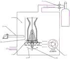
图2燃烧室内表面电弧沉积后冷却装置图Figure 2 Diagram of the cooling device after arc deposition on the surface of the combustion chamber
图3燃烧室外表面电弧沉积后冷却装置图Figure 3 Diagram of the cooling device after arc deposition on the surface of the combustion chamber
具体实施方式Detailed ways
下面结合附图和具体实施例对本发明作进一步详细的描述:Below in conjunction with accompanying drawing and specific embodiment the present invention is described in further detail:
本发明一种新型电弧离子镀设备冷却方法,包括如下步骤:A novel arc ion plating equipment cooling method of the present invention comprises the following steps:
第一步:待发动机燃烧室内表面沉积涂层结束后自然冷却Step 1: Natural cooling after the deposition coating on the surface of the engine combustion chamber is completed
根据铌钨合金燃烧室形状和尺寸加工的内外表面金属阴极靶材并进行除油;对合格的发动机燃烧室内外表面进行除油酸洗,超声清洗后待沉积涂层;将清洗后的发动机燃烧室放在产品台上,保持燃烧室内表面与靶材在同一圆心上,同时避免靶材和产品相互接触,如图2所示;通过真空系统4抽真空至1×10⁻²Pa以下,按相应工艺参数沉积钼层,待沉积完成后,喷管进行冷却。According to the shape and size of the niobium-tungsten alloy combustion chamber, the inner and outer surface metal cathode targets are processed and degreased; the inner and outer surfaces of the qualified engine combustion chamber are degreased and pickled, and the coating is to be deposited after ultrasonic cleaning; the cleaned engine is burned Place the chamber on the product table, keep the surface of the combustion chamber and the target on the same center, and avoid the contact between the target and the product, as shown in Figure 2; through the
在涂层制备过程中,涂层制备设备中原有水冷通道(一般用于冷却靶材以及炉壁)一直处于开启状态,待燃烧室内外表面沉积钼涂层完成后,工件处于高温状态,实时测温装置监测工件温度,使得工件在原涂层制备高真空状态下自然冷却至500℃~900℃,避免涂层内部产生较大内应力使得涂层出现起皮、开裂等现象。During the coating preparation process, the original water cooling channel (generally used to cool the target and furnace wall) in the coating preparation equipment is always open. After the molybdenum coating is deposited on the inner and outer surfaces of the combustion chamber, the workpiece is in a high temperature state. The temperature device monitors the temperature of the workpiece, so that the workpiece is naturally cooled to 500 ℃ ~ 900 ℃ under the high vacuum state of the original coating preparation, so as to avoid the phenomenon of peeling and cracking of the coating due to the large internal stress inside the coating.
第二步:开启气淬风冷装置加速工件冷却Step 2: Turn on the gas quenching and air cooling device to accelerate the cooling of the workpiece
待工件在高真空状态下自然冷却至500℃~900℃,开启保护气体流量控制装置通入保护气体(如氩气),调节风扇,待通入气体量与机械泵-分子泵双级泵真空系统抽出气体量达到一定平衡时,使得炉内气压保持在1×100~1×10⁻³范围内波动。After the workpiece is naturally cooled to 500 ℃ ~ 900 ℃ in a high vacuum state, turn on the protective gas flow control device to feed the protective gas (such as argon), adjust the fan, and wait for the gas volume to be introduced to be the same as the vacuum of the mechanical pump-molecular pump two-stage pump. When the amount of gas pumped out by the system reaches a certain balance, the air pressure in the furnace is kept fluctuating within the range of 1×100 to 1×10⁻³ .
研究发现:当工件温度处于700~900℃时,将风扇的风速档位调节至低速档位时,调节气体流量使炉内气压在1×10⁻²~1×10⁻³范围内波动;当工件温度处于500~700℃时,将风扇的风速档位调节至中速档位时,调节气体流量使炉内气压在1×10⁻¹~1×10⁻³范围内波动;当工件温度处于500℃以下时,将风扇的风速档位调节至高速档位时,调节气体流量使炉内气压在1×100~1×10⁻²范围内波动。在此冷却条件下,工件冷却速度较快,且膜层质量影响相对较小。The research found that: when the temperature of the workpiece is 700-900 ℃, when the wind speed gear of the fan is adjusted to the low-speed gear, the gas flow rate is adjusted to make the air pressure in the furnace fluctuate in the range of 1×10⁻² to 1×10⁻³ ; when When the temperature of the workpiece is between 500 and 700°C, adjust the wind speed of the fan to the medium speed gear, and adjust the gas flow to make the air pressure in the furnace fluctuate within the range of 1×10⁻¹ to 1×10⁻³ ; when the temperature of the workpiece is at When the temperature is below 500°C, when the wind speed gear of the fan is adjusted to a high speed gear, the gas flow rate is adjusted so that the pressure in the furnace fluctuates within the range of 1×100 to 1×10⁻² . Under this cooling condition, the cooling rate of the workpiece is faster, and the influence of the film quality is relatively small.
第三步:停止通入保护气体,准备出炉Step 3: Stop feeding the protective gas and prepare for the furnace
待工件表面温度达到30~60℃时,停止保护气体通道,关闭风扇,按操作要求分级关闭真空系统各级,钼层冷却结束,工件出炉检验。When the surface temperature of the workpiece reaches 30-60°C, stop the protective gas channel, turn off the fan, and shut down the vacuum system at different stages according to the operation requirements. After the cooling of the molybdenum layer is completed, the workpiece is released for inspection.
第四步:待发动机燃烧室外表面处理Step 4: Treat the outer surface of the engine combustion chamber
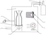
将清洗后的发动机燃烧室垂直放在产品台上,如图3所示。将真空室抽真空至1×10⁻²Pa以下,按相应工艺参数对工件外表面沉积钼层,待沉积完成后,喷管进行冷却。Place the cleaned engine combustion chamber vertically on the product table, as shown in Figure 3. The vacuum chamber is evacuated to below 1×10⁻² Pa, and the molybdenum layer is deposited on the outer surface of the workpiece according to the corresponding process parameters. After the deposition is completed, the nozzle is cooled.
待燃烧室外表面沉积钼涂层完成后,通过实时测温装置监测工件温度。当工件在高真空状态下自然冷却至500℃~900℃时,开启保护气体流量控制装置通入保护气体(如氩气),将风扇调节相对应风速状态,使得炉内气压保持在1×100~1×10⁻³范围内波动。待工件表面温度达到30~60℃时,关闭保护气体通道,关闭风扇及水冷通道,按操作要求分级关闭真空系统各级,钼层冷却结束,工件出炉检验。After the molybdenum coating is deposited on the surface of the combustion chamber, the temperature of the workpiece is monitored by a real-time temperature measuring device. When the workpiece is naturally cooled to 500 ° C ~ 900 ° C in a high vacuum state, turn on the protective gas flow control device to feed the protective gas (such as argon), and adjust the fan to the corresponding wind speed so that the air pressure in the furnace is kept at 1×10 Fluctuates within the range of0 to 1×10⁻³ . When the surface temperature of the workpiece reaches 30-60°C, close the protective gas channel, the fan and the water cooling channel, and close the vacuum system at different stages according to the operation requirements. After the cooling of the molybdenum layer is completed, the workpiece is released for inspection.
对出炉后的工件检验表面质量,保证涂层光滑致密,附着力好,无明显色差、色斑。Check the surface quality of the workpiece after it is released from the furnace to ensure that the coating is smooth and dense, with good adhesion and no obvious color difference or stain.
本发明给出一种适用于上述冷却方法的冷却装置,图2燃烧室内表面电弧沉积后冷却装置图,待钼层沉积完成后,启动该冷却装置与水冷装置一起加速工件冷却。图3燃烧室外表面电弧沉积后冷却装置图,待钼层沉积完成后,启动该冷却装置与水冷通道一起加速工件冷却。该冷却装置包括保护气体通道1、工件实时温度监测装置3、保护气体的流量控制装置2、及可调速级风扇7等。The present invention provides a cooling device suitable for the above cooling method. Figure 2 is a diagram of the cooling device after arc deposition on the surface of the combustion chamber. After the molybdenum layer is deposited, the cooling device is started to accelerate the cooling of the workpiece together with the water cooling device. Figure 3 is a diagram of the cooling device after arc deposition on the outer surface of the combustion chamber. After the deposition of the molybdenum layer is completed, the cooling device is activated to accelerate the cooling of the workpiece together with the water cooling channel. The cooling device includes a
涂层制备炉上方设置保护气体通道,通过保护气体的流量控制装置与气瓶连接;发动机燃烧室放置在涂层制备炉内的工作台上,工件实时温度监测装置穿过所述涂层制备炉安装,用于检测冷却过程中发动机燃烧室表面温度;可调速级风扇放置在所述涂层制备炉内,与保护气体的流量控制装置一起维持冷却过程中炉内气压在1×100~1×10⁻³范围内波动。A protective gas channel is set above the coating preparation furnace, which is connected to the gas cylinder through the flow control device of the protective gas; the engine combustion chamber is placed on the workbench in the coating preparation furnace, and the workpiece real-time temperature monitoring device passes through the coating preparation furnace Installed to detect the surface temperature of the engine combustion chamber during the cooling process; the adjustable-speed fan is placed in the coating preparation furnace, and together with the flow control device of the protective gas, the air pressure in the furnace during the cooling process is maintained at 1×100 ~ Fluctuates in the range of 1×10⁻³ .
工件实时温度监测装置包括安装在结构件上的热电偶以及配备有隔离挡板9的传动及控制机构,所述热电偶位置对着发动机燃烧室的直线段;在工件涂层制备过程中隔离挡板把热电偶隔离在外,在工件冷却过程中隔离挡板抽离,热电偶正常工作,有效保护该装置不受镀膜影响。本发明给出一优选实例中,所述热电偶的位置满足将发动机燃烧室上下倒装后,对着喷管出口下方与喉部之间位置。The workpiece real-time temperature monitoring device includes a thermocouple installed on the structure and a transmission and control mechanism equipped with an
保护气体的流量控制装置包括气体的输入输出装置、气体流量控制器、气体通道隔离板以及控制系统组成;所述气体的输入输出装置用于向保护气体通道提供保护气体,以及用于涂层制备炉中的气体回收;所述气体流量控制器控制保护气体通道内的气体流量;气体通道隔离板用于在涂层制备时切断所述保护气体通道以及涂层制备炉,在冷却时打开保护气体通道;所述控制系统用于控制气体的输入输出装置、气体流量控制器、气体通道隔离板。The flow control device of the protective gas includes a gas input and output device, a gas flow controller, a gas channel isolation plate and a control system; the gas input and output device is used to provide protective gas to the protective gas channel and for coating preparation Gas recovery in the furnace; the gas flow controller controls the gas flow in the protective gas channel; the gas channel isolation plate is used to cut off the protective gas channel and the coating preparation furnace during coating preparation, and open the protective gas during cooling channel; the control system is used to control gas input and output devices, gas flow controllers, and gas channel isolation plates.
说明:设备所用风扇一般选择工业类具有中高低三个档位的小风扇即可满足设备需求。Note: The fans used in the equipment generally choose industrial small fans with three gears of medium, high and low to meet the needs of the equipment.
实施例1Example 1
以制造一种铌钨合金发动机燃烧室尺寸为

1.铌钨合金发动机燃烧室及靶材的准备阶段1. The preparation stage of the combustion chamber and target of niobium-tungsten alloy engine
根据发动机燃烧室的图纸要求,进行燃烧室加工
2.铌钨合金发动机燃烧室内表面制备钼涂层2. Preparation of molybdenum coating on the combustion chamber surface of niobium-tungsten alloy engine
将清洗后的发动机燃烧室放在产品台上,保持燃烧室内表面与靶材在同一圆心上,同时避免靶材和产品相互接触,如图2所示。开启水冷通道8,通过真空系统4将真空室抽真空至1×10⁻²Pa以下,控制弧源系统5以及运转系统6开始沉积钼层,工艺参数为起弧电流为80A,电弧电压30V,沉积时间为8min,待沉积完成后,沉积的钼涂层厚度在50±15μm。Put the cleaned engine combustion chamber on the product table, keep the inner surface of the combustion chamber on the same center as the target, and avoid contact between the target and the product, as shown in Figure 2. Turn on the
待燃烧室内表面沉积钼涂层完成后,通过实时测温装置3监测工件温度。当工件在高真空状态下自然冷却至850℃以下时,开启保护气体流量控制装置2通入保护气体,将风扇7调节至较低风速状态,使得炉内气压保持在1×10⁻²~1×10⁻³范围内波动;当工件温度处于680℃时,将风扇的风速档位调节至中速档位时,调节气体流量使炉内气压在1×10⁻¹~1×10⁻³范围内波动;当工件温度处于450℃时,将风扇的风速档位调节至高速档位时,调节气体流量使炉内气压在1×100~1×10⁻²范围内波动,如图2所示。待工件表面温度达到45℃时,停止保护气体通道1,关闭风扇7及水冷通道8,按操作要求分级关闭真空系统各级,钼层冷却结束,工件出炉检验。After the molybdenum coating is deposited on the surface of the combustion chamber, the temperature of the workpiece is monitored by the real-time
3.铌钨合金发动机燃烧室外表面制备钼涂层3. Preparation of molybdenum coating on the surface of the combustion chamber of niobium-tungsten alloy engine
将内表面沉积结束后的燃烧室放在产品台上,如图3所示。抽真空至1×10⁻²Pa以下,开始沉积钼层,工艺参数为起弧电流为100A,电弧电压30V,沉积时间为3h,待沉积完成后,Place the combustion chamber after the deposition on the inner surface on the product table, as shown in Figure 3. Vacuum down to below 1×10⁻² Pa, start to deposit the molybdenum layer, the process parameters are arc starting current 100A, arc voltage 30V, deposition time 3h, after the deposition is completed,
沉积的钼涂层厚度在50±15μm。The thickness of the deposited molybdenum coating is 50±15 μm.
待燃烧室外表面沉积钼涂层完成后,通过实时测温装置3监测工件温度。当工件在高真空状态下自然冷却至800℃以下时,开启保护气体流量控制装置2通入保护气体,将风扇7调节至较低风速状态,使得炉内气压保持在1×100~1×10⁻³范围内波动;当工件温度处于630℃时,将风扇的风速档位调节至中速档位时,调节气体流量使炉内气压在1×10⁻¹~1×10⁻³范围内波动;当工件温度处于480℃时,将风扇的风速档位调节至高速档位时,调节气体流量使炉内气压在1×100~1×10⁻²范围内波动,如图3所示。待工件表面温度达到45℃时,停止保护气体通道,关闭风扇及水冷通道,按操作要求分级关闭真空系统各级,钼层冷却结束,工件出炉检验。After the molybdenum coating is deposited on the outer surface of the combustion chamber, the temperature of the workpiece is monitored by the real-time
4.检验4. Inspection
制备得到的钼层致密且附着力良好,采用机械测量法对钼层厚度进行检测,涂层厚度复合技术要求。The prepared molybdenum layer is dense and has good adhesion. The thickness of the molybdenum layer is detected by mechanical measurement, and the coating thickness meets the technical requirements.
试验表明:该制备冷却技术实现铌钨合金发动机燃烧室尺寸为
实施例2Example 2
以制造一种铌钨合金发动机燃烧室尺寸为

1.铌钨合金发动机燃烧室及靶材的准备阶段1. The preparation stage of the combustion chamber and target of niobium-tungsten alloy engine
根据发动机燃烧室的图纸要求,进行燃烧室加工
2.铌钨合金发动机燃烧室内表面制备钼涂层2. Preparation of molybdenum coating on the combustion chamber surface of niobium-tungsten alloy engine
将清洗后的发动机燃烧室放在产品台上,保持燃烧室内表面与靶材在同一圆心上,同时避免靶材和产品相互接触,如图2所示。开启水冷通道,将真空室抽真空至1×10⁻²Pa以下,开始沉积钼层,工艺参数为起弧电流为60A,电弧电压30V,沉积时间为5min,待沉积完成后,沉积的钼涂层厚度在50±15μm。Put the cleaned engine combustion chamber on the product table, keep the inner surface of the combustion chamber on the same center as the target, and avoid contact between the target and the product, as shown in Figure 2. Turn on the water-cooling channel, evacuate the vacuum chamber to below 1×10⁻² Pa, and start depositing the molybdenum layer. The process parameters are 60A starting current, 30V arc voltage, and 5min deposition time. The layer thickness is 50±15 μm.
待燃烧室内表面沉积钼涂层完成后,通过实时测温装置监测工件温度。当工件在高真空状态下自然冷却至800℃以下时,开启保护气体流量控制装置通入保护气体,将风扇调节至较低风速状态,使得炉内气压保持在1×10⁻²~1×10⁻³范围内波动;当工件温度处于600℃时,将风扇的风速档位调节至中速档位时,调节气体流量使炉内气压在1×10⁻¹~1×10⁻³范围内波动;当工件温度处于400℃时,将风扇的风速档位调节至高速档位时,调节气体流量使炉内气压在1×100~1×10⁻²范围内波动,待工件表面温度达到45℃时,停止保护气体通道,关闭风扇及水冷通道,按操作要求分级关闭真空系统各级,钼层冷却结束,工件出炉检验。After the molybdenum coating is deposited on the surface of the combustion chamber, the temperature of the workpiece is monitored by a real-time temperature measuring device. When the workpiece is naturally cooled to below 800°C in a high vacuum state, turn on the protective gas flow control device to feed the protective gas, and adjust the fan to a lower wind speed state, so that the air pressure in the furnace is maintained at 1×10⁻² ~ 1×10 Fluctuate in the range of-3 ; when the temperature of the workpiece is 600°C, adjust the fan speed gear to the medium speed gear, adjust the gas flow to make the furnace air pressure fluctuate in the range of 1×10⁻¹ ~ 1×10⁻³ ; When the temperature of the workpiece is at 400°C, adjust the wind speed gear of the fan to the high speed gear, adjust the gas flow to make the air pressure in the furnace fluctuate within the range of 1×100 to 1×10⁻² , and wait until the surface temperature of the workpiece reaches 45 At ℃, stop the protective gas channel, close the fan and water cooling channel, and close the vacuum system at all levels according to the operation requirements. The cooling of the molybdenum layer is completed, and the workpiece is inspected out of the furnace.
3.铌钨合金发动机燃烧室外表面制备钼涂层3. Preparation of molybdenum coating on the surface of the combustion chamber of niobium-tungsten alloy engine
将内表面沉积结束后的燃烧室放在产品台上,如图3所示。抽真空至1×10⁻²Pa以下,开始沉积钼层,工艺参数为起弧电流为80A,电弧电压30V,沉积时间为1.5h,待沉积完成后,钼涂层厚度在50±15μm。Place the combustion chamber after the deposition on the inner surface on the product table, as shown in Figure 3. Vacuum down to below 1×10⁻² Pa to start depositing the molybdenum layer. The process parameters are 80A starting current, 30V arc voltage, and 1.5h deposition time. After the deposition is completed, the thickness of the molybdenum coating is 50±15μm.
待燃烧室外表面沉积钼涂层完成后,通过实时测温装置监测工件温度。当工件在高真空状态下自然冷却至840℃以下时,开启保护气体流量控制装置2通入保护气体,将风扇7调节至较低风速状态,使得炉内气压保持在1×100~1×10⁻³范围内波动;当工件温度处于600℃时,将风扇的风速档位调节至中速档位时,调节气体流量使炉内气压在1×10⁻¹~1×10⁻³范围内波动;当工件温度处于450℃时,将风扇的风速档位调节至高速档位时,调节气体流量使炉内气压在1×100~1×10⁻²范围内波动,待工件表面温度达到45℃时,停止保护气体通道,关闭风扇及水冷通道,按操作要求分级关闭真空系统各级,钼层冷却结束,工件出炉检验。After the molybdenum coating is deposited on the surface of the combustion chamber, the temperature of the workpiece is monitored by a real-time temperature measuring device. When the workpiece is naturally cooled to below 840°C in a high vacuum state, the protective gas
4.检验4. Inspection
制备得到的钼层致密且附着力良好,采用机械测量法对钼层厚度进行检测,涂层厚度复合技术要求。The prepared molybdenum layer is dense and has good adhesion. The thickness of the molybdenum layer is detected by mechanical measurement, and the coating thickness meets the technical requirements.
试验表明:该制备冷却技术实现铌钨合金发动机燃烧室尺寸为
以上所述,仅为本发明最佳的具体实施方式,但本发明的保护范围并不局限于此,任何熟悉本技术领域的技术人员在本发明揭露的技术范围内,可轻易想到的变化或替换,都应涵盖在本发明的保护范围之内。The above description is only the best specific implementation mode of the present invention, but the scope of protection of the present invention is not limited thereto. Any person skilled in the art can easily conceive of changes or modifications within the technical scope disclosed in the present invention. Replacement should be covered within the protection scope of the present invention.
本发明说明书中未作详细描述的内容属于本领域专业技术人员的公知技术。The content that is not described in detail in the specification of the present invention belongs to the well-known technology of those skilled in the art.
Claims (9)
Priority Applications (1)
| Application Number | Priority Date | Filing Date | Title |
|---|---|---|---|
| CN202310131112.XACN116240503B (en) | 2023-02-17 | 2023-02-17 | Arc ion plating equipment cooling method and device |
Applications Claiming Priority (1)
| Application Number | Priority Date | Filing Date | Title |
|---|---|---|---|
| CN202310131112.XACN116240503B (en) | 2023-02-17 | 2023-02-17 | Arc ion plating equipment cooling method and device |
Publications (2)
| Publication Number | Publication Date |
|---|---|
| CN116240503Atrue CN116240503A (en) | 2023-06-09 |
| CN116240503B CN116240503B (en) | 2025-06-17 |
Family
ID=86635667
Family Applications (1)
| Application Number | Title | Priority Date | Filing Date |
|---|---|---|---|
| CN202310131112.XAActiveCN116240503B (en) | 2023-02-17 | 2023-02-17 | Arc ion plating equipment cooling method and device |
Country Status (1)
| Country | Link |
|---|---|
| CN (1) | CN116240503B (en) |
Citations (12)
| Publication number | Priority date | Publication date | Assignee | Title |
|---|---|---|---|---|
| JPH0566056U (en)* | 1992-02-07 | 1993-08-31 | 東芝タンガロイ株式会社 | Coating treatment device with forced cooling mechanism |
| US6277201B1 (en)* | 1998-04-30 | 2001-08-21 | Asm Japan K.K. | CVD apparatus for forming thin films using liquid reaction material |
| JP2004018996A (en)* | 2002-06-20 | 2004-01-22 | Shin Meiwa Ind Co Ltd | Method of measuring substrate temperature in vacuum film forming apparatus and vacuum film forming apparatus |
| US20160172226A1 (en)* | 2014-12-11 | 2016-06-16 | Applied Materials, Inc. | Gas cooled minimal contact area(mca) electrostatic chuck(esc) for aluminum nitride(aln) pvd process |
| CN108351306A (en)* | 2015-10-28 | 2018-07-31 | 应用材料公司 | Apparatus for processing material on a substrate, cooling arrangement for processing apparatus, and method for measuring properties of material processed on a substrate |
| CN108588650A (en)* | 2018-04-26 | 2018-09-28 | 航天材料及工艺研究所 | A kind of method of vacuum cathode arc arc source device and depositing coating |
| CN208776829U (en)* | 2018-05-02 | 2019-04-23 | 北京七星华创集成电路装备有限公司 | A cooling chamber for magnetron sputtering coating equipment |
| CN110079781A (en)* | 2019-04-11 | 2019-08-02 | 北京北方华创微电子装备有限公司 | Cooling chamber, ALN buffer growth process equipment and cooling treatment method |
| CN209456559U (en)* | 2019-01-08 | 2019-10-01 | 成都中电熊猫显示科技有限公司 | The cooling system of substrate for film deposition |
| CN213803975U (en)* | 2020-11-09 | 2021-07-27 | 河北胤丞光电科技有限公司 | Cooling system of vacuum coating machine |
| CN214250191U (en)* | 2021-02-20 | 2021-09-21 | 浙江云度新材料科技有限公司 | Cooling device of continuous magnetron sputtering production line |
| KR20230021887A (en)* | 2021-08-06 | 2023-02-14 | (주) 비엘에스 | Cooling structure of Arc source |
- 2023
- 2023-02-17CNCN202310131112.XApatent/CN116240503B/enactiveActive
Patent Citations (12)
| Publication number | Priority date | Publication date | Assignee | Title |
|---|---|---|---|---|
| JPH0566056U (en)* | 1992-02-07 | 1993-08-31 | 東芝タンガロイ株式会社 | Coating treatment device with forced cooling mechanism |
| US6277201B1 (en)* | 1998-04-30 | 2001-08-21 | Asm Japan K.K. | CVD apparatus for forming thin films using liquid reaction material |
| JP2004018996A (en)* | 2002-06-20 | 2004-01-22 | Shin Meiwa Ind Co Ltd | Method of measuring substrate temperature in vacuum film forming apparatus and vacuum film forming apparatus |
| US20160172226A1 (en)* | 2014-12-11 | 2016-06-16 | Applied Materials, Inc. | Gas cooled minimal contact area(mca) electrostatic chuck(esc) for aluminum nitride(aln) pvd process |
| CN108351306A (en)* | 2015-10-28 | 2018-07-31 | 应用材料公司 | Apparatus for processing material on a substrate, cooling arrangement for processing apparatus, and method for measuring properties of material processed on a substrate |
| CN108588650A (en)* | 2018-04-26 | 2018-09-28 | 航天材料及工艺研究所 | A kind of method of vacuum cathode arc arc source device and depositing coating |
| CN208776829U (en)* | 2018-05-02 | 2019-04-23 | 北京七星华创集成电路装备有限公司 | A cooling chamber for magnetron sputtering coating equipment |
| CN209456559U (en)* | 2019-01-08 | 2019-10-01 | 成都中电熊猫显示科技有限公司 | The cooling system of substrate for film deposition |
| CN110079781A (en)* | 2019-04-11 | 2019-08-02 | 北京北方华创微电子装备有限公司 | Cooling chamber, ALN buffer growth process equipment and cooling treatment method |
| CN213803975U (en)* | 2020-11-09 | 2021-07-27 | 河北胤丞光电科技有限公司 | Cooling system of vacuum coating machine |
| CN214250191U (en)* | 2021-02-20 | 2021-09-21 | 浙江云度新材料科技有限公司 | Cooling device of continuous magnetron sputtering production line |
| KR20230021887A (en)* | 2021-08-06 | 2023-02-14 | (주) 비엘에스 | Cooling structure of Arc source |
Also Published As
| Publication number | Publication date |
|---|---|
| CN116240503B (en) | 2025-06-17 |
Similar Documents
| Publication | Publication Date | Title |
|---|---|---|
| CN103695858B (en) | A kind of multi-functional full-automatic ion film coating machine for cutter coat deposition and using method thereof | |
| TWI616558B (en) | Method for producing parts for plasma treatment device | |
| CN101307428A (en) | Combined vacuum coating process of magnetron sputtering and multisphere ion plating | |
| RU2425173C2 (en) | Installation for combined ion-plasma treatment | |
| CN112063962B (en) | Method for preparing uniform coating on complex profile surface by PS-PVD | |
| CN103160773A (en) | Method for prolonging service life of engine thermal barrier coating by controlling components of thermal growth oxide layer | |
| CN102618846A (en) | Method and device for depositing super-hard film through multi-torch plasma spray CVD (Chemical Vapor Deposition) method | |
| CN104278234B (en) | Preparation technology for self-lubricating coating with wide temperature range of room temperature to 800 DEG C | |
| CN110408903A (en) | Preparation method of multiple multi-layer coating on tool surface | |
| CN110724923A (en) | Preparation method of ion-impregnated tungsten carbide layer with surface gradient nanostructure | |
| CN101294284A (en) | A Plasma Surface Composite Strengthening Method for Erosion Resistance and Fatigue Resistance | |
| CN103938157B (en) | A kind of ZrNbAlN superlattice coating and preparation method | |
| CN113789496A (en) | Preparation method of self-healing gradient thermal barrier coating | |
| CN105420673A (en) | Diamond-like micro-nano coating for rubber mold and preparation method | |
| CN115502672B (en) | A method and device for realizing extremely low damage processing of metal matrix composite materials | |
| CN116516290A (en) | Thermal barrier coating with composite structure and preparation method and application thereof | |
| CN116240503A (en) | A novel arc ion plating equipment cooling method and device | |
| KR20170128675A (en) | A method of forming a multi-element alloy thin film composite | |
| RU2691166C1 (en) | Method of applying protective coatings and device for its implementation | |
| CN114188210B (en) | A surface treatment method for a deposition surface inside an etching chamber of a metal etcher | |
| CN114107916B (en) | Plating method for keeping blade air film cooling hole smooth | |
| JPH06322528A (en) | Sputtering method and sputtering apparatus | |
| TWI493065B (en) | Vacuum device | |
| CN116574992A (en) | High-performance thermal barrier coating and preparation method thereof | |
| CN113564558B (en) | Chemical vapor deposition and annealing continuous processing device, method and application |
Legal Events
| Date | Code | Title | Description |
|---|---|---|---|
| PB01 | Publication | ||
| PB01 | Publication | ||
| SE01 | Entry into force of request for substantive examination | ||
| SE01 | Entry into force of request for substantive examination | ||
| GR01 | Patent grant | ||
| GR01 | Patent grant |