CN116236934A - A device for generating and cooling bubble water - Google Patents
A device for generating and cooling bubble waterDownload PDFInfo
- Publication number
- CN116236934A CN116236934ACN202310192597.3ACN202310192597ACN116236934ACN 116236934 ACN116236934 ACN 116236934ACN 202310192597 ACN202310192597 ACN 202310192597ACN 116236934 ACN116236934 ACN 116236934A
- Authority
- CN
- China
- Prior art keywords
- cooling
- channel
- carbon dioxide
- gas
- tank body
- Prior art date
- Legal status (The legal status is an assumption and is not a legal conclusion. Google has not performed a legal analysis and makes no representation as to the accuracy of the status listed.)
- Pending
Links
- 238000001816coolingMethods0.000titleclaimsabstractdescription123
- XLYOFNOQVPJJNP-UHFFFAOYSA-NwaterSubstancesOXLYOFNOQVPJJNP-UHFFFAOYSA-N0.000titleclaimsabstractdescription108
- CURLTUGMZLYLDI-UHFFFAOYSA-NCarbon dioxideChemical compoundO=C=OCURLTUGMZLYLDI-UHFFFAOYSA-N0.000claimsabstractdescription98
- 229910002092carbon dioxideInorganic materials0.000claimsabstractdescription49
- 239000001569carbon dioxideSubstances0.000claimsabstractdescription49
- 239000007788liquidSubstances0.000claimsabstractdescription41
- 239000003507refrigerantSubstances0.000claimsabstractdescription30
- 230000001105regulatory effectEffects0.000claimsdescription8
- 239000004606Fillers/ExtendersSubstances0.000claimsdescription7
- 239000008213purified waterSubstances0.000claimsdescription5
- 230000003993interactionEffects0.000claimsdescription3
- 230000000149penetrating effectEffects0.000claims2
- 238000000746purificationMethods0.000claims1
- 238000003860storageMethods0.000description6
- 238000004519manufacturing processMethods0.000description5
- 238000000034methodMethods0.000description5
- 239000000498cooling waterSubstances0.000description4
- 238000005057refrigerationMethods0.000description4
- 238000004891communicationMethods0.000description2
- 230000004048modificationEffects0.000description2
- 238000012986modificationMethods0.000description2
- 239000000243solutionSubstances0.000description2
- 238000004458analytical methodMethods0.000description1
- 230000009286beneficial effectEffects0.000description1
- 238000004140cleaningMethods0.000description1
- 238000010924continuous productionMethods0.000description1
- 230000001276controlling effectEffects0.000description1
- 230000007547defectEffects0.000description1
- 230000000694effectsEffects0.000description1
- 238000005516engineering processMethods0.000description1
- 238000002347injectionMethods0.000description1
- 239000007924injectionSubstances0.000description1
- 238000009434installationMethods0.000description1
- 239000000126substanceSubstances0.000description1
Images


Classifications
- B—PERFORMING OPERATIONS; TRANSPORTING
- B01—PHYSICAL OR CHEMICAL PROCESSES OR APPARATUS IN GENERAL
- B01F—MIXING, e.g. DISSOLVING, EMULSIFYING OR DISPERSING
- B01F23/00—Mixing according to the phases to be mixed, e.g. dispersing or emulsifying
- B01F23/20—Mixing gases with liquids
- B01F23/23—Mixing gases with liquids by introducing gases into liquid media, e.g. for producing aerated liquids
- B01F23/236—Mixing gases with liquids by introducing gases into liquid media, e.g. for producing aerated liquids specially adapted for aerating or carbonating beverages
- B01F23/2363—Mixing systems, i.e. flow charts or diagrams; Arrangements, e.g. comprising controlling means
- B—PERFORMING OPERATIONS; TRANSPORTING
- B01—PHYSICAL OR CHEMICAL PROCESSES OR APPARATUS IN GENERAL
- B01F—MIXING, e.g. DISSOLVING, EMULSIFYING OR DISPERSING
- B01F23/00—Mixing according to the phases to be mixed, e.g. dispersing or emulsifying
- B01F23/20—Mixing gases with liquids
- B01F23/23—Mixing gases with liquids by introducing gases into liquid media, e.g. for producing aerated liquids
- B01F23/237—Mixing gases with liquids by introducing gases into liquid media, e.g. for producing aerated liquids characterised by the physical or chemical properties of gases or vapours introduced in the liquid media
- B01F23/2376—Mixing gases with liquids by introducing gases into liquid media, e.g. for producing aerated liquids characterised by the physical or chemical properties of gases or vapours introduced in the liquid media characterised by the gas being introduced
- B01F23/23762—Carbon dioxide
- B01F23/237621—Carbon dioxide in beverages
- B—PERFORMING OPERATIONS; TRANSPORTING
- B01—PHYSICAL OR CHEMICAL PROCESSES OR APPARATUS IN GENERAL
- B01F—MIXING, e.g. DISSOLVING, EMULSIFYING OR DISPERSING
- B01F35/00—Accessories for mixers; Auxiliary operations or auxiliary devices; Parts or details of general application
- B01F35/90—Heating or cooling systems
- B01F35/92—Heating or cooling systems for heating the outside of the receptacle, e.g. heated jackets or burners
- B—PERFORMING OPERATIONS; TRANSPORTING
- B01—PHYSICAL OR CHEMICAL PROCESSES OR APPARATUS IN GENERAL
- B01F—MIXING, e.g. DISSOLVING, EMULSIFYING OR DISPERSING
- B01F35/00—Accessories for mixers; Auxiliary operations or auxiliary devices; Parts or details of general application
- B01F35/90—Heating or cooling systems
- B01F2035/98—Cooling
- B—PERFORMING OPERATIONS; TRANSPORTING
- B01—PHYSICAL OR CHEMICAL PROCESSES OR APPARATUS IN GENERAL
- B01F—MIXING, e.g. DISSOLVING, EMULSIFYING OR DISPERSING
- B01F2101/00—Mixing characterised by the nature of the mixed materials or by the application field
- B01F2101/06—Mixing of food ingredients
- B01F2101/14—Mixing of ingredients for non-alcoholic beverages; Dissolving sugar in water
Landscapes
- Chemical & Material Sciences (AREA)
- Chemical Kinetics & Catalysis (AREA)
Abstract
Translated fromChinese
Description
Translated fromChinese技术领域technical field
本发明涉及气泡水生产设备的技术领域,具体涉及一种气泡水的生成及冷却装置。The invention relates to the technical field of sparkling water production equipment, in particular to a generating and cooling device for sparkling water.
背景技术Background technique
气泡水是一种比较健康的饮料,人们对充气饮料的认可度也越来越高。为了满足口感的需求,制备气泡水气泡水机的混合箱内应保持较低的温度,从而使制备的气泡水具有更好的口感。传统的气泡水机一般包括水箱和混合箱,水箱或混合箱中的一个上设置冷却器,以使气泡水保持较低的温度。如果是为水箱设置冷却器,当水箱内的低温水送入混合箱制备气泡水时,会存在冷量的流失,导致冷水进入混合箱后水温上升,气泡水口感不好。如果是在混合箱上设置冷却器,一般冷却能力不足,存在达不到制备气泡水所需的低温。Sparkling water is a relatively healthy drink, and people are increasingly accepting sparkling drinks. In order to meet the demand for taste, the temperature in the mixing box of the sparkling water machine should be kept low, so that the prepared sparkling water has a better taste. A traditional sparkling water machine generally includes a water tank and a mixing tank, and a cooler is arranged on one of the water tank or the mixing tank to keep the sparkling water at a lower temperature. If a cooler is installed for the water tank, when the low-temperature water in the water tank is sent into the mixing tank to prepare sparkling water, there will be a loss of cooling capacity, which will cause the water temperature to rise after the cold water enters the mixing tank, and the sparkling water will not taste good. If a cooler is installed on the mixing box, the cooling capacity is generally insufficient, and the low temperature required for preparing sparkling water cannot be reached.
例如,公告号为CN215457328U的中国专利申请公开了一种气泡水机,包括:水箱,所述水箱用于盛放气泡水水源,且所述水箱与大气导通;制冷装置,所述制冷装置封闭设置,且所述制冷装置的进水口与所述水箱的出水口导通连接;混合器,所述混合器封闭设置,所述混合器的顶端与所述水箱的顶端通过第一气管导通连接,且所述第一气管上安装有控制所述第一气管通断的安全阀,所述混合器的进水口与所述制冷装置的出水口通过进水管导通连接,所述混合器的排水口用于排出气泡水;气瓶,所述气瓶内储存气体,且所述气瓶的出气口与所述混合器的进气口通过进气管导通连接,所述进气管上安装有控制所述进气管通断的第一压力阀,所述第一压力阀的外控口与所述混合器的进水口导通连接,当所述混合器内的压力大于预设值时,所述第一压力阀关闭。For example, the Chinese patent application with the notification number CN215457328U discloses a sparkling water machine, including: a water tank, the water tank is used to hold the sparkling water source, and the water tank is connected to the atmosphere; a refrigeration device, the refrigeration device is closed set, and the water inlet of the refrigeration device is connected to the water outlet of the water tank; the mixer is arranged in a closed manner, and the top of the mixer is connected to the top of the water tank through the first air pipe , and a safety valve for controlling the on-off of the first air pipe is installed on the first air pipe, the water inlet of the mixer is connected to the water outlet of the refrigeration device through the water inlet pipe, and the drain of the mixer The mouth is used to discharge the sparkling water; the gas cylinder stores gas in the gas cylinder, and the gas outlet of the gas cylinder is connected with the air inlet of the mixer through the air inlet pipe, and the air inlet pipe is equipped with a control The first pressure valve for on-off of the air intake pipe, the external control port of the first pressure valve is connected to the water inlet of the mixer, when the pressure in the mixer is greater than the preset value, the The first pressure valve is closed.
现有技术中,制作气泡水的设备一般,先对净水进行冷却后与二氧化碳相混合,但是在混合的过程中,若混合时间较长,则容易使得气泡水的温度上升,进而影响气泡水的质量;若混合时间较短,则容易出现二氧化碳和净水混合不充分的情况,也会影响气泡水的质量,此外,若通过加长净水的冷却时间以将净水的温度进一步降低,容易出现冷却周期过长而影响生产效率的情况,且会造成资源浪费。In the prior art, the equipment for making sparkling water generally cools clean water and then mixes it with carbon dioxide. However, if the mixing time is long during the mixing process, the temperature of the sparkling water will easily rise, which will affect the quality of the sparkling water. If the mixing time is short, the carbon dioxide and clean water are likely to be mixed insufficiently, which will also affect the quality of sparkling water. In addition, if the temperature of the clean water is further reduced by lengthening the cooling time of the clean water, it is easy to If the cooling cycle is too long, the production efficiency will be affected, and resources will be wasted.
发明内容Contents of the invention
为了克服上述气泡水生产时冷却时间难以把控的技术缺陷,本发明提供一种通过混合前后二次冷却以实现高效且高质量的气泡水的生成及冷却装置。In order to overcome the above-mentioned technical defect that it is difficult to control the cooling time during the production of sparkling water, the present invention provides a device for generating and cooling efficient and high-quality sparkling water through secondary cooling before and after mixing.
为了解决上述问题,本发明按以下技术方案予以实现的:In order to solve the above problems, the present invention is realized according to the following technical solutions:
本发明公开一种气泡水的生成及冷却装置,包括净水供给组件、冷却罐、气液混合组件和二氧化碳供给组件;The invention discloses a generating and cooling device for bubble water, which comprises a clean water supply component, a cooling tank, a gas-liquid mixing component and a carbon dioxide supply component;
其中,所述冷却罐包括罐体、冷媒管道和冷却盘管,所述冷媒管道和冷却盘管位于所述罐体内,所述罐体上具有连通罐体内腔的第一冷却入口和第一冷却出口,所述冷却盘管的两端分别凸出到罐体的上端以形成第二冷却入口和第二冷却出口;Wherein, the cooling tank includes a tank body, a refrigerant pipeline and a cooling coil, the refrigerant pipeline and the cooling coil are located in the tank, and the tank body has a first cooling inlet and a first cooling inlet connected to the inner cavity of the tank. an outlet, the two ends of the cooling coil protrude respectively to the upper end of the tank to form a second cooling inlet and a second cooling outlet;
所述净水供给组件与所述第一冷却入口通过管道连接,所述第一冷却出口通过管道连接到所述气液混合组件的输入端,所述气液混合组件的输出端通过管道连接到所述第二冷却入口,所述二氧化碳供给组与所述气液混合组件通过管道连接,所述第二冷却出口向外输出气泡水。The clean water supply assembly is connected to the first cooling inlet through a pipeline, the first cooling outlet is connected to the input end of the gas-liquid mixing assembly through a pipeline, and the output end of the gas-liquid mixing assembly is connected to the air-liquid mixing assembly through a pipeline. The second cooling inlet, the carbon dioxide supply group are connected to the gas-liquid mixing assembly through pipelines, and the second cooling outlet outputs sparkling water to the outside.
作为本发明的优选实施,所述罐体上端的中部还设有一排气管。As a preferred implementation of the present invention, an exhaust pipe is also provided in the middle of the upper end of the tank body.
作为本发明的优选实施,所述第一冷却入口嵌入至所述罐体的上端,所述第一冷却出口嵌入至所述罐体的下端。As a preferred implementation of the present invention, the first cooling inlet is embedded in the upper end of the tank body, and the first cooling outlet is embedded in the lower end of the tank body.
作为本发明的优选实施,所述冷媒管道的冷媒入口和冷媒出口分别设置在所述罐体的上端面,所述冷媒管道的主体位于所述罐体的中部。As a preferred implementation of the present invention, the refrigerant inlet and the refrigerant outlet of the refrigerant pipeline are respectively arranged on the upper end surface of the tank body, and the main body of the refrigerant pipeline is located in the middle of the tank body.
作为本发明的优选实施,所述冷媒管道位于所述罐体的部分绕所述罐体的中心盘旋形成多层结构。As a preferred implementation of the present invention, the part of the refrigerant pipeline located in the tank body spirals around the center of the tank body to form a multi-layer structure.
作为本发明的优选实施,所述冷却盘管设置在所述冷媒管道的外周,所述冷却盘管的盘绕部分位于所述罐体的下端部,与所述冷媒管道错位设置。As a preferred implementation of the present invention, the cooling coil is arranged on the outer periphery of the refrigerant pipeline, and the coiled part of the cooling coil is located at the lower end of the tank body, and is arranged in a dislocation with the refrigerant pipeline.
作为本发明的优选实施,所述气液混合组件包括依次连接的气液混合器和气液延长器。As a preferred implementation of the present invention, the gas-liquid mixing assembly includes a gas-liquid mixer and a gas-liquid extender connected in sequence.
作为本发明的优选实施,所述气液混合器包括阀体、叶轮、阀芯和弹簧;As a preferred implementation of the present invention, the gas-liquid mixer includes a valve body, an impeller, a valve core and a spring;
其中,所述阀体具有贯穿阀体的第一通道、以及穿设阀体并与第一通道互通的第二通道;所述第一通道的入口与所述第一冷却出口连接,所述第二通道与所述二氧化碳供给组件连接,所述第一通道的出口连接到气液延长器;Wherein, the valve body has a first channel passing through the valve body, and a second channel passing through the valve body and communicating with the first channel; the inlet of the first channel is connected with the first cooling outlet, and the first channel is The second channel is connected to the carbon dioxide supply assembly, and the outlet of the first channel is connected to the gas-liquid extender;
从第一冷却出口流出的冷水与从二氧化碳供给组件流出的二氧化碳于所述阀体内混合后经第一通道的出口排出;所述第一通道与第二通道相互垂直;The cold water flowing out from the first cooling outlet and the carbon dioxide flowing out from the carbon dioxide supply assembly are mixed in the valve body and then discharged through the outlet of the first channel; the first channel and the second channel are perpendicular to each other;
所述叶轮设于所述第一通道内并位于第一通道与第二通道的交汇处,且所述叶轮可沿所述第二通道的轴向往返移动;The impeller is arranged in the first channel and is located at the intersection of the first channel and the second channel, and the impeller can move back and forth along the axial direction of the second channel;
所述阀芯用于调节从第二通道流入阀体内的二氧化碳的流量,所述阀芯与叶轮连接并受叶轮驱动;The spool is used to adjust the flow of carbon dioxide flowing into the valve body from the second channel, and the spool is connected to and driven by the impeller;
所述弹簧位于所述阀体的上端部,所述弹簧设置在所述阀芯与所述阀体之间,所述弹簧用于使所述阀芯向下复位。The spring is located at the upper end of the valve body, the spring is arranged between the valve core and the valve body, and the spring is used to reset the valve core downward.
作为本发明的优选实施,所述叶轮具有第一状态及第二状态,第一流动介质与所述叶轮的相互作用可使叶轮在第一状态与第二状态中切换:As a preferred implementation of the present invention, the impeller has a first state and a second state, and the interaction between the first flow medium and the impeller can make the impeller switch between the first state and the second state:
第一状态下,所述叶轮停止不动或叶轮仅转动,所述阀芯调节所述第二通道通过二氧化碳的流量最低或所述阀芯关闭第二通道;In the first state, the impeller stops or the impeller only rotates, the valve core adjusts the flow of carbon dioxide through the second channel to be the lowest or the valve core closes the second channel;
第二状态下,所述叶轮旋转并沿着所述第二通道轴向位移,所述叶轮带动阀芯移动并使阀芯调节所述第二通道通过二氧化碳的流量增大。In the second state, the impeller rotates and axially displaces along the second channel, the impeller drives the valve core to move and makes the valve core adjust the increase of the flow of carbon dioxide passing through the second channel.
作为本发明的优选实施,所述净水供给组件包括净水储存器和调压阀;As a preferred implementation of the present invention, the clean water supply assembly includes a clean water storage and a pressure regulating valve;
所述二氧化碳供给组件包括依次连接的液态二氧化碳储存器、减压阀、调流阀和单向阀;The carbon dioxide supply assembly includes a liquid carbon dioxide storage, a pressure reducing valve, a flow regulating valve and a one-way valve connected in sequence;
所述第二冷却出口通过管道连接到快速接头上以输出冷却后的气泡水。The second cooling outlet is connected to the quick connector through a pipeline to output the cooled sparkling water.
与现有技术相比,本发明的有益效果是:Compared with prior art, the beneficial effect of the present invention is:
本发明所述的气泡水的生成及冷却装置创造性地对冷却罐的结构以及冷却水路进行改进,使得只需要设置单一的冷却罐即可形成两个冷却回路,以实现在混合之前进入到冷却罐中对净水进行第一次冷却,在净水与二氧化碳混合后再次进入到冷却罐中进行第二次冷却。在与二氧化碳混合前的净水足够冷却能够确保二氧化碳与净水混合的质量,经过混合流程后的气泡水再次进入到冷却罐中进行二次冷却,能够确保最终输出的气泡水的温度足够低,且独立的两个冷却水路不会因为二次冷却而显著降低气泡水的生成效率,本发明能够在不额外设置更多设备的前提下,高速且高质量地生产冷却的气泡水。The generating and cooling device of the bubble water according to the present invention creatively improves the structure of the cooling tank and the cooling water circuit, so that only a single cooling tank is required to form two cooling circuits, so as to realize that it enters the cooling tank before mixing The clean water is cooled for the first time in the tank, and after the clean water is mixed with carbon dioxide, it enters the cooling tank again for the second cooling. The clean water before mixing with carbon dioxide is cooled enough to ensure the quality of mixing carbon dioxide and clean water. After the mixing process, the sparkling water enters the cooling tank for secondary cooling, which can ensure that the temperature of the final output sparkling water is low enough. And the two independent cooling water channels will not significantly reduce the generation efficiency of sparkling water due to secondary cooling, and the present invention can produce cooled sparkling water at high speed and high quality without additional equipment.
附图说明Description of drawings
下面结合附图对本发明的具体实施方式作进一步详细的说明,其中:Below in conjunction with accompanying drawing, specific embodiment of the present invention is described in further detail, wherein:
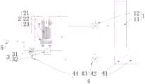
图1是本发明的整体结构示意图;Fig. 1 is the overall structural representation of the present invention;
图2是本发明的冷却罐的结构示意图;Fig. 2 is the structural representation of cooling tank of the present invention;
图3是本发明的气液混合器的结构示意图;Fig. 3 is the structural representation of gas-liquid mixer of the present invention;
图中:In the picture:
1、净水供给组件;11、净水储存器;12、调压阀;1. Purified water supply component; 11. Purified water storage; 12. Pressure regulating valve;
2、冷却罐;21、罐体;22、冷媒管道;23、冷却盘管;24、第一冷却入口;25、第一冷却出口;26、第二冷却入口;27、第二冷却出口;2. Cooling tank; 21. Tank body; 22. Refrigerant pipeline; 23. Cooling coil; 24. First cooling inlet; 25. First cooling outlet; 26. Second cooling inlet; 27. Second cooling outlet;
3、气液混合组件;31、气液混合器;311、阀体;312、叶轮;313、阀芯;314、弹簧;32、气液延长器;3. Gas-liquid mixing assembly; 31. Gas-liquid mixer; 311. Valve body; 312. Impeller; 313. Valve core; 314. Spring; 32. Gas-liquid extender;
4、二氧化碳供给组件;41、液态二氧化碳储存器;42、减压阀;43、调流阀;44、单向阀;4. Carbon dioxide supply components; 41. Liquid carbon dioxide storage; 42. Pressure reducing valve; 43. Regulating valve; 44. One-way valve;
5、快速接头。5. Quick connector.
具体实施方式Detailed ways
以下结合附图对本发明的优选实施例进行说明,应当理解,此处所描述的优选实施例仅用于说明和解释本发明,并不用于限定本发明。The preferred embodiments of the present invention will be described below in conjunction with the accompanying drawings. It should be understood that the preferred embodiments described here are only used to illustrate and explain the present invention, and are not intended to limit the present invention.
以下在实施方式中详细叙述本发明的详细特征以及优点,其内容足以使任何熟悉相关技术者,了解本发明的技术内容并据以实施,且根据本说明书所揭露的内容、权利要求及附图,任何熟悉相关技术者可轻易地理解本发明相关的目的及优点。以下的实施例是进一步详细说明本发明的观点,但非以任何观点限制本发明的范畴。The detailed features and advantages of the present invention are described in detail below in the embodiments, the content of which is sufficient to enable anyone familiar with the relevant art to understand the technical content of the present invention and implement it accordingly, and according to the content disclosed in this specification, claims and drawings , anyone familiar with the related art can easily understand the related objects and advantages of the present invention. The following examples are to further describe the viewpoints of the present invention in detail, but not to limit the scope of the present invention in any way.
并且,以下将以附图揭露本发明的实施例,为达图面整洁的目的,一些现有惯用的结构与元件在附图可能会以简单示意的方式绘示之,且本案附图中部分的特征可能会略为放大或改变其比例或尺寸,以达到便于理解与观看本发明的技术特征的目的,但这并非用于限定本发明。此外,附图中提供有坐标轴,以利于理解元件的相对位置关系和作动方向。Moreover, the following will disclose the embodiments of the present invention with the accompanying drawings. For the purpose of cleaning the drawings, some existing conventional structures and components may be shown in a simple schematic way in the drawings, and some of the drawings in this case The features may be slightly enlarged or changed in proportion or size to facilitate understanding and viewing of the technical features of the present invention, but this is not intended to limit the present invention. In addition, coordinate axes are provided in the drawings to facilitate understanding of relative positional relationships and actuating directions of components.
需要理解的是,术语“上”、“下”等指示的方位或位置关系为基于附图所示的方位或位置关系,仅是为了便于描述本发明和简化描述,而不是指示或暗示所指的装置或元件必须具有特定的方位、以特定的方位构造和操作,因此不能理解为对本发明的限制。此外,术语“第一”、“第二”仅用于描述目的,而不能理解为指示或暗示相对重要性或者隐含指明所指示的技术特征的数量。由此,限定有“第一”、“第二”的特征可以明示或者隐含地包括一个或者更多个该特征。在本发明的描述中,除非另有说明,“多个”的含义是两个或两个以上。It should be understood that the orientation or positional relationship indicated by the terms "upper", "lower" and the like are based on the orientation or positional relationship shown in the drawings, and are only for the convenience of describing the present invention and simplifying the description, rather than indicating or implying Any device or element must have a specific orientation, be constructed and operate in a specific orientation and therefore should not be construed as limiting the invention. In addition, the terms "first" and "second" are used for descriptive purposes only, and cannot be interpreted as indicating or implying relative importance or implicitly specifying the quantity of indicated technical features. Thus, a feature defined as "first" and "second" may explicitly or implicitly include one or more of these features. In the description of the present invention, unless otherwise specified, "plurality" means two or more.
在本发明的描述中,需要说明的是,除非另有明确的规定和限定,术语“安装”、“相连”、“连接”应做广义理解,例如,可以是固定连接,也可以是可拆卸连接,或一体地连接;可以是机械连接,也可以是电连接;可以是直接相连,也可以通过中间媒介间接相连,可以是两个元件内部的连通。In the description of the present invention, it should be noted that unless otherwise specified and limited, the terms "installation", "connection" and "connection" should be understood in a broad sense, for example, it can be a fixed connection or a detachable connection. Connected, or integrally connected; it may be mechanically connected or electrically connected; it may be directly connected or indirectly connected through an intermediary, and it may be the internal communication of two components.
另外,下文中可能会使用「端」、「部」、「部分」、「区域」、「处」等术语来描述特定元件与结构或是其上或其之间的特定技术特征,但这些元件与结构并不受这些术语所限制。下文中也可能会使用「及/或(and/or)」,其是指包含了一或多个所列相关元件或结构的其中一者或全部的组合。此外,以下文中也可能使用「实质上」、「基本上」、「约」或「大约」等术语,其与尺寸、浓度、温度或其他物理或化学性质或特性的范围结合使用时,为意欲涵盖可能存在于该等性质或特性的范围的上限及/或下限中的偏差、或表示容许制造公差或分析过程中所造成的可接受偏离,但仍可达到所预期的效果。In addition, terms such as "end", "portion", "part", "region", and "place" may be used hereinafter to describe specific elements and structures or specific technical features on or between them, but these elements and structures are not limited by these terms. "And/or (and/or)" may also be used hereinafter, which refers to a combination of one or all of one or more listed related elements or structures. In addition, the terms "substantially", "substantially", "about" or "approximately" may also be used hereinafter, when used in conjunction with ranges of size, concentration, temperature or other physical or chemical properties or characteristics, it is intended that Deviations that may exist in the upper and/or lower limits of the range for such properties or characteristics are covered, or represent tolerances of manufacturing tolerances or acceptable deviations resulting from analytical procedures and still achieve the desired effect.
再者,除非另有定义,本文所使用的所有词汇或术语,包括技术和科学上的词汇与术语等包含其通常的意涵,其意涵能够被熟悉此技术领域者所理解。更进一步的说,上述的词汇或术语的定义,在本说明书中应被解读为与本发明相关技术领域包含一致的意涵。除非有特别明确的定义,这些词汇或术语将不被解释为过于理想化的或正式的意涵。Moreover, unless otherwise defined, all words or terms used herein, including technical and scientific terms and terms, include their usual meanings, and their meanings can be understood by those skilled in the technical field. Furthermore, the definitions of the above-mentioned words or terms in this specification should be interpreted as having consistent meanings with those in the relevant technical fields of the present invention. Unless specifically defined, these words or terms will not be interpreted in an overly idealized or formal meaning.
如图1~图3所示,为本发明所述的气泡水的生成及冷却装置的优选结构。As shown in Fig. 1 to Fig. 3, it is a preferable structure of the generation and cooling device of sparkling water according to the present invention.
如图1所示,本发明公开一种气泡水的生成及冷却装置,包括净水供给组件1、冷却罐2、气液混合组件3和二氧化碳供给组件4;As shown in Figure 1, the present invention discloses a sparkling water generation and cooling device, including a clean water supply assembly 1, a
其中,所述冷却罐2包括罐体21、冷媒管道22和冷却盘管23,所述冷媒管道22和冷却盘管23位于所述罐体21内,所述罐体21上具有连通罐体21内腔的第一冷却入口24和第一冷却出口25,所述冷却盘管23的两端分别凸出到罐体21的上端以形成第二冷却入口26和第二冷却出口27;Wherein, the
如图2所示,所述净水供给组件1与所述第一冷却入口24通过管道连接,所述第一冷却出口25通过管道连接到所述气液混合组件3的输入端,所述气液混合组件3的输出端通过管道连接到所述第二冷却入口26,所述二氧化碳供给组与所述气液混合组件3通过管道连接,所述第二冷却出口27向外输出气泡水。As shown in Figure 2, the clean water supply assembly 1 is connected to the
具体地,所述净水供给组件1包括净水储存器11和调压阀12;所述二氧化碳供给组件4包括依次连接的液态二氧化碳储存器41、减压阀42、调流阀43和单向阀44;所述第二冷却出口27通过管道连接到快速接头5上以输出冷却后的气泡水。所述罐体21上端的中部还设有一排气管。所述第一冷却入口24嵌入至所述罐体21的上端,所述第一冷却出口25嵌入至所述罐体21的下端。Specifically, the clean water supply assembly 1 includes a
本发明可以降低二氧化碳供气压力,制取同样品质的气泡水,消耗的二氧化碳气体更少。本专利的二氧化碳供应压力只要保证在2-2.5kgf之间即可,目前现有技术几乎都是采用高压气体喷射进罐体的方式进行制取气泡水,其要求二氧化碳气体压力至少要在4kgf以上,因此从气体消耗量及安全性来说,本发明具有明显的优势。The invention can reduce the carbon dioxide gas supply pressure, produce the same quality sparkling water, and consume less carbon dioxide gas. The supply pressure of carbon dioxide in this patent only needs to be between 2-2.5kgf. At present, almost all existing technologies use high-pressure gas injection into the tank to produce sparkling water, which requires that the pressure of carbon dioxide gas should be at least 4kgf. , so the present invention has obvious advantages in terms of gas consumption and safety.
由于本发明采用管道式的气液混合方式,使得制取的气泡水可以源源不断,只需要保证二氧化碳供给组件4能够对二氧化碳持续供给,且对气泡水的水温没有要求,就可持续的制取气泡水。现有技术一般采用一定容量的罐体,然后往罐体内充入二氧化碳气体,因此其制取气泡水是有限的,并不能满足连续产出气泡水的要求。Since the present invention adopts a pipeline-type gas-liquid mixing method, the produced sparkling water can be produced in a steady stream. It only needs to ensure that the carbon
作为本发明的优选实施,所述冷媒管道22的冷媒入口和冷媒出口分别设置在所述罐体21的上端面,所述冷媒管道22的主体位于所述罐体21的中部。As a preferred implementation of the present invention, the refrigerant inlet and the refrigerant outlet of the
作为本发明的优选实施,所述冷媒管道22位于所述罐体21的部分绕所述罐体21的中心盘旋形成多层结构。As a preferred implementation of the present invention, the part of the
作为本发明的优选实施,所述冷却盘管23设置在所述冷媒管道22的外周,所述冷却盘管23的盘绕部分位于所述罐体21的下端部,与所述冷媒管道22错位设置。As a preferred implementation of the present invention, the cooling
作为本发明的优选实施,所述气液混合组件3包括依次连接的气液混合器31和气液延长器32。As a preferred implementation of the present invention, the gas-
如图3所示,作为本发明的优选实施,所述气液混合器31包括阀体311、叶轮312、阀芯313和弹簧314;As shown in Figure 3, as a preferred implementation of the present invention, the gas-
其中,所述阀体311具有贯穿阀体311的第一通道、以及穿设阀体311并与第一通道互通的第二通道;所述第一通道的入口与所述第一冷却出口25连接,所述第二通道与所述二氧化碳供给组件4连接,所述第一通道的出口连接到气液延长器32;Wherein, the valve body 311 has a first channel passing through the valve body 311 and a second channel passing through the valve body 311 and communicating with the first channel; the inlet of the first channel is connected to the
从第一冷却出口25流出的冷水与从二氧化碳供给组件4流出的二氧化碳于所述阀体311内混合后经第一通道的出口排出;所述第一通道与第二通道相互垂直;The cold water flowing out from the
所述叶轮312设于所述第一通道内并位于第一通道与第二通道的交汇处,且所述叶轮312可沿所述第二通道的轴向往返移动;The impeller 312 is arranged in the first channel and is located at the intersection of the first channel and the second channel, and the impeller 312 can move back and forth along the axial direction of the second channel;
所述阀芯313用于调节从第二通道流入阀体311内的二氧化碳的流量,所述阀芯313与叶轮312连接并受叶轮312驱动;The
所述弹簧314位于所述阀体311的上端部,所述弹簧314设置在所述阀芯313与所述阀体311之间,所述弹簧314用于使所述阀芯313向下复位。The
作为本发明的优选实施,所述叶轮312具有第一状态及第二状态,第一流动介质与所述叶轮312的相互作用可使叶轮312在第一状态与第二状态中切换:As a preferred implementation of the present invention, the impeller 312 has a first state and a second state, and the interaction between the first flow medium and the impeller 312 can make the impeller 312 switch between the first state and the second state:
第一状态下,所述叶轮312停止不动或叶轮312仅转动,所述阀芯313调节所述第二通道通过二氧化碳的流量最低或所述阀芯313关闭第二通道;In the first state, the impeller 312 stops or the impeller 312 only rotates, the
第二状态下,所述叶轮312旋转并沿着所述第二通道轴向位移,所述叶轮312带动阀芯313移动并使阀芯313调节所述第二通道通过二氧化碳的流量增大。In the second state, the impeller 312 rotates and axially displaces along the second channel, and the impeller 312 drives the
本发明所述的的工作原理是:The working principle described in the present invention is:
本发明所述的气泡水的生成及冷却装置创造性地对冷却罐2的结构以及冷却水路进行改进,使得只需要设置单一的冷却罐2即可形成两个冷却回路,以实现在混合之前进入到冷却罐2中对净水进行第一次冷却,在净水与二氧化碳混合后再次进入到冷却罐2中进行第二次冷却。在与二氧化碳混合前的净水足够冷却能够确保二氧化碳与净水混合的质量,经过混合流程后的气泡水再次进入到冷却罐2中进行二次冷却,能够确保最终输出的气泡水的温度足够低,且独立的两个冷却水路不会因为二次冷却而显著降低气泡水的生成效率,本发明能够在不额外设置更多设备的前提下,高速且高质量地生产冷却的气泡水。The generation and cooling device of the bubble water described in the present invention creatively improves the structure of the
本实施例所述的气泡水的生成及冷却装置的其它结构参见现有技术。For other structures of the bubble water generation and cooling device described in this embodiment, refer to the prior art.
以上所述,仅是本发明的较佳实施例而已,并非对本发明作任何形式上的限制,故凡是未脱离本发明技术方案内容,依据本发明的技术实质对以上实施例所作的任何修改、等同变化与修饰,均仍属于本发明技术方案的范围内。The above is only a preferred embodiment of the present invention, and is not intended to limit the present invention in any form. Therefore, any modification, Equivalent changes and modifications all still belong to the scope of the technical solutions of the present invention.
Claims (10)
Priority Applications (1)
| Application Number | Priority Date | Filing Date | Title |
|---|---|---|---|
| CN202310192597.3ACN116236934A (en) | 2023-03-02 | 2023-03-02 | A device for generating and cooling bubble water |
Applications Claiming Priority (1)
| Application Number | Priority Date | Filing Date | Title |
|---|---|---|---|
| CN202310192597.3ACN116236934A (en) | 2023-03-02 | 2023-03-02 | A device for generating and cooling bubble water |
Publications (1)
| Publication Number | Publication Date |
|---|---|
| CN116236934Atrue CN116236934A (en) | 2023-06-09 |
Family
ID=86629298
Family Applications (1)
| Application Number | Title | Priority Date | Filing Date |
|---|---|---|---|
| CN202310192597.3APendingCN116236934A (en) | 2023-03-02 | 2023-03-02 | A device for generating and cooling bubble water |
Country Status (1)
| Country | Link |
|---|---|
| CN (1) | CN116236934A (en) |
Citations (4)
| Publication number | Priority date | Publication date | Assignee | Title |
|---|---|---|---|---|
| WO2014128355A1 (en)* | 2013-02-22 | 2014-08-28 | Wetend Technologies Oy | An arrangement for mixing a fluid to a process liquid and a method of operating the arrangement |
| CN211712717U (en)* | 2020-02-25 | 2020-10-20 | 益库(青岛)电子机械有限公司 | Bubble water preparing module of bubble water machine |
| CN114225737A (en)* | 2021-12-21 | 2022-03-25 | 佛山市顺德区基诺德电器制造有限公司 | Mixing device, mixing valve and mixing equipment |
| CN116098460A (en)* | 2023-03-02 | 2023-05-12 | 佛山市顺德区基诺德电器制造有限公司 | Multifunctional refrigeration drinking machine |
- 2023
- 2023-03-02CNCN202310192597.3Apatent/CN116236934A/enactivePending
Patent Citations (4)
| Publication number | Priority date | Publication date | Assignee | Title |
|---|---|---|---|---|
| WO2014128355A1 (en)* | 2013-02-22 | 2014-08-28 | Wetend Technologies Oy | An arrangement for mixing a fluid to a process liquid and a method of operating the arrangement |
| CN211712717U (en)* | 2020-02-25 | 2020-10-20 | 益库(青岛)电子机械有限公司 | Bubble water preparing module of bubble water machine |
| CN114225737A (en)* | 2021-12-21 | 2022-03-25 | 佛山市顺德区基诺德电器制造有限公司 | Mixing device, mixing valve and mixing equipment |
| CN116098460A (en)* | 2023-03-02 | 2023-05-12 | 佛山市顺德区基诺德电器制造有限公司 | Multifunctional refrigeration drinking machine |
Similar Documents
| Publication | Publication Date | Title |
|---|---|---|
| CN107583480A (en) | Microbubble generator and preparation method thereof | |
| CN219353609U (en) | Low-temperature bubble water preparation device | |
| CN204240630U (en) | Air conditioner and refrigerating system thereof | |
| CN116236934A (en) | A device for generating and cooling bubble water | |
| CN116098460B (en) | Multifunctional refrigeration drinking machine | |
| CN206037527U (en) | A water supply system for refrigeration plant | |
| CN216534917U (en) | Water route board and multifunctional water dispenser with same | |
| CN107362706A (en) | A kind of device that water and carbon dioxide are mixed to generation carbonated water immediately | |
| JP2006336988A (en) | Heat exchange device and heat pump water heater using the same | |
| CN219661454U (en) | Cold white boiled water system and water drinking device | |
| CN208751358U (en) | A heat exchange device with enhanced convective heat transfer at the phase interface | |
| CN114158940B (en) | Waterway plate and multifunctional water dispenser having the same | |
| CN222265040U (en) | A water inlet conversion device and drinking water equipment | |
| CN201706817U (en) | Dispenser | |
| CN107917557A (en) | Throttling sleeve and air conditioner | |
| CN219742474U (en) | A soda machine water circuit system and a soda machine | |
| CN203163333U (en) | Refrigerant circulation device for liquid gas refrigeration | |
| CN116358195A (en) | Mixing method of refrigerant in heat exchange equipment | |
| CN221012902U (en) | Bubble water machine | |
| CN220757196U (en) | Bubble water machine | |
| CN218485653U (en) | Bubble water preparation facilities | |
| CN118925527A (en) | Plug-in mixer | |
| CN217447392U (en) | Water drinking equipment | |
| CN217716066U (en) | Molten salt storage device and molten salt heat storage system | |
| CN223005039U (en) | Thermal cycle subassembly and heating system |
Legal Events
| Date | Code | Title | Description |
|---|---|---|---|
| PB01 | Publication | ||
| PB01 | Publication | ||
| SE01 | Entry into force of request for substantive examination | ||
| SE01 | Entry into force of request for substantive examination |