CN116236319A - Heart valve replacement device, system, and artificial valve anchoring method - Google Patents
Heart valve replacement device, system, and artificial valve anchoring methodDownload PDFInfo
- Publication number
- CN116236319A CN116236319ACN202211606675.1ACN202211606675ACN116236319ACN 116236319 ACN116236319 ACN 116236319ACN 202211606675 ACN202211606675 ACN 202211606675ACN 116236319 ACN116236319 ACN 116236319A
- Authority
- CN
- China
- Prior art keywords
- clamping
- heart
- valve replacement
- annular support
- heart valve
- Prior art date
- Legal status (The legal status is an assumption and is not a legal conclusion. Google has not performed a legal analysis and makes no representation as to the accuracy of the status listed.)
- Pending
Links
Images


Classifications
- A—HUMAN NECESSITIES
- A61—MEDICAL OR VETERINARY SCIENCE; HYGIENE
- A61F—FILTERS IMPLANTABLE INTO BLOOD VESSELS; PROSTHESES; DEVICES PROVIDING PATENCY TO, OR PREVENTING COLLAPSING OF, TUBULAR STRUCTURES OF THE BODY, e.g. STENTS; ORTHOPAEDIC, NURSING OR CONTRACEPTIVE DEVICES; FOMENTATION; TREATMENT OR PROTECTION OF EYES OR EARS; BANDAGES, DRESSINGS OR ABSORBENT PADS; FIRST-AID KITS
- A61F2/00—Filters implantable into blood vessels; Prostheses, i.e. artificial substitutes or replacements for parts of the body; Appliances for connecting them with the body; Devices providing patency to, or preventing collapsing of, tubular structures of the body, e.g. stents
- A61F2/02—Prostheses implantable into the body
- A61F2/24—Heart valves ; Vascular valves, e.g. venous valves; Heart implants, e.g. passive devices for improving the function of the native valve or the heart muscle; Transmyocardial revascularisation [TMR] devices; Valves implantable in the body
- A61F2/2412—Heart valves ; Vascular valves, e.g. venous valves; Heart implants, e.g. passive devices for improving the function of the native valve or the heart muscle; Transmyocardial revascularisation [TMR] devices; Valves implantable in the body with soft flexible valve members, e.g. tissue valves shaped like natural valves
- A—HUMAN NECESSITIES
- A61—MEDICAL OR VETERINARY SCIENCE; HYGIENE
- A61F—FILTERS IMPLANTABLE INTO BLOOD VESSELS; PROSTHESES; DEVICES PROVIDING PATENCY TO, OR PREVENTING COLLAPSING OF, TUBULAR STRUCTURES OF THE BODY, e.g. STENTS; ORTHOPAEDIC, NURSING OR CONTRACEPTIVE DEVICES; FOMENTATION; TREATMENT OR PROTECTION OF EYES OR EARS; BANDAGES, DRESSINGS OR ABSORBENT PADS; FIRST-AID KITS
- A61F2/00—Filters implantable into blood vessels; Prostheses, i.e. artificial substitutes or replacements for parts of the body; Appliances for connecting them with the body; Devices providing patency to, or preventing collapsing of, tubular structures of the body, e.g. stents
- A61F2/02—Prostheses implantable into the body
- A61F2/24—Heart valves ; Vascular valves, e.g. venous valves; Heart implants, e.g. passive devices for improving the function of the native valve or the heart muscle; Transmyocardial revascularisation [TMR] devices; Valves implantable in the body
- A61F2/2409—Support rings therefor, e.g. for connecting valves to tissue
- A—HUMAN NECESSITIES
- A61—MEDICAL OR VETERINARY SCIENCE; HYGIENE
- A61F—FILTERS IMPLANTABLE INTO BLOOD VESSELS; PROSTHESES; DEVICES PROVIDING PATENCY TO, OR PREVENTING COLLAPSING OF, TUBULAR STRUCTURES OF THE BODY, e.g. STENTS; ORTHOPAEDIC, NURSING OR CONTRACEPTIVE DEVICES; FOMENTATION; TREATMENT OR PROTECTION OF EYES OR EARS; BANDAGES, DRESSINGS OR ABSORBENT PADS; FIRST-AID KITS
- A61F2220/00—Fixations or connections for prostheses classified in groups A61F2/00 - A61F2/26 or A61F2/82 or A61F9/00 or A61F11/00 or subgroups thereof
- A61F2220/0008—Fixation appliances for connecting prostheses to the body
Landscapes
- Health & Medical Sciences (AREA)
- Engineering & Computer Science (AREA)
- Biomedical Technology (AREA)
- Cardiology (AREA)
- Oral & Maxillofacial Surgery (AREA)
- Transplantation (AREA)
- Heart & Thoracic Surgery (AREA)
- Vascular Medicine (AREA)
- Life Sciences & Earth Sciences (AREA)
- Animal Behavior & Ethology (AREA)
- General Health & Medical Sciences (AREA)
- Public Health (AREA)
- Veterinary Medicine (AREA)
- Prostheses (AREA)
Abstract
Translated fromChinese
Description
Translated fromChinese技术领域technical field
本申请实施例涉及医疗器械技术领域,尤其涉及一种心脏瓣膜置换装置、系统及人工瓣膜锚定方法。The embodiments of the present application relate to the technical field of medical devices, and in particular to a heart valve replacement device, system, and artificial valve anchoring method.
背景技术Background technique
二尖瓣,也被称为左房室瓣,是形成在左心室和左心房之间的屏障。正常情况下,二尖瓣的开合是由左心房和左心室间的压力差调节的,在心脏舒张期,左心房压力大于左心室,二尖瓣打开,反之,在心脏收缩期,左心室压力大于左心房,二尖瓣关闭。二尖瓣结构复杂,由瓣环、瓣叶、腱索和乳头肌构成,其中任何一部分发生器质性或功能性改变,都可能会引起二尖瓣关闭不全,即在心脏收缩期二尖瓣不能完全关闭,使得左心室的血液反向流入左心室。二尖瓣关闭不全的治疗方法包括瓣膜修复和置换,其中瓣膜修复是常见首选的治疗方法,但是瓣膜置换是最终根本的解决方法。The mitral valve, also known as the left atrioventricular valve, is the barrier that forms between the left ventricle and the left atrium. Under normal circumstances, the opening and closing of the mitral valve is regulated by the pressure difference between the left atrium and the left ventricle. During diastole, the pressure of the left atrium is greater than that of the left ventricle, and the mitral valve opens. Conversely, during systole, the left ventricle The pressure is greater than that of the left atrium, and the mitral valve closes. The structure of the mitral valve is complex, consisting of the valve ring, valve leaflets, chordae and papillary muscles. Any organic or functional changes in any part of the mitral valve may cause mitral regurgitation, that is, the mitral valve in systole Does not close completely, allowing blood from the left ventricle to flow backwards into the left ventricle. The treatment of mitral valve insufficiency includes valve repair and replacement, among which valve repair is often the first choice of treatment, but valve replacement is the ultimate solution.
心脏瓣膜置换可经外科或经导管介入的手术方式进行,其中,对于存在心功能低下、合并症多、高龄等高危因素,而不适于进行外科手术的二尖瓣关闭不全的患者而言,可以接受经导管介入方式治疗。Heart valve replacement can be performed by surgery or transcatheter intervention. Among them, for patients with high-risk factors such as low heart function, many complications, and advanced age, who are not suitable for surgery, mitral valve insufficiency can be performed. received transcatheter interventional therapy.
目前,经导管主动脉瓣膜置换已是一种非常成熟的主动脉瓣膜疾病的治疗手段,市场上已有多家经导管主动脉瓣膜产品,而对于经导管二尖瓣瓣膜,近年来虽然出现多种结构设计及输送方式,但是大部分都处于研究性阶段,主要存在以下制约因素:第一:由于二尖瓣结构复杂,与主动脉瓣相比,二尖瓣整体结构呈D型,瓣环尺寸较大,钙化较少,不能为人工瓣膜提供足够的支撑力,使其固定在病变的二尖瓣处;第二:在解剖结构上,由于左室流出道与二尖瓣前瓣叶相邻,人工二尖瓣瓣膜的植入还可能会引起左室流出道梗阻(LVOTO),这在人工瓣膜设计时也是需要考虑避免的;此外,由于二尖瓣的瓣环尺寸较大,若人工瓣膜为单层支架,与主动脉瓣相比,需要更大直径的支架,此将导致人工瓣膜对应的瓣叶面积也相应增大,并造成瓣叶耐疲劳性降低,同时还增加了输送系统的尺寸,造成血管并发症的风险增大的问题。At present, transcatheter aortic valve replacement is a very mature treatment for aortic valve disease. There are many transcatheter aortic valve products on the market. However, most of them are in the research stage, and there are mainly the following constraints: First, due to the complex structure of the mitral valve, compared with the aortic valve, the overall structure of the mitral valve is D-shaped, and the annulus The larger size and less calcification cannot provide enough support for the artificial valve to fix it at the diseased mitral valve; second: in terms of anatomy, since the left ventricular outflow tract is adjacent to the anterior leaflet of the mitral valve, The implantation of artificial mitral valve may also cause left ventricular outflow tract obstruction (LVOTO), which also needs to be considered in the design of artificial valve; in addition, due to the large size of the mitral valve ring, if the artificial valve is Compared with the aortic valve, the single-layer stent requires a larger diameter stent, which will lead to a corresponding increase in the leaflet area of the prosthetic valve, which will reduce the fatigue resistance of the leaflet and increase the size of the delivery system , resulting in an increased risk of vascular complications.
有鉴于此,亟需一种心脏瓣膜置换产品,可增加人工瓣膜的定位效果,提高瓣膜置换手术的成功率。In view of this, there is an urgent need for a heart valve replacement product, which can increase the positioning effect of artificial valves and improve the success rate of valve replacement operations.
发明内容Contents of the invention
鉴于上述问题,本申请提供一种心脏瓣膜置换装置、系统及人工瓣膜锚定方法,以克服上述问题或者至少部分地解决上述问题。In view of the above problems, the present application provides a heart valve replacement device, system and artificial valve anchoring method to overcome the above problems or at least partly solve the above problems.
根据本申请的第一方面,提供一种心脏瓣膜置换装置,包括环形支撑件,其具有相对设置的内表面和外表面;瓣叶结构,其包括沿所述环形支撑件的周向设于所述环形支撑件的内表面的多个人工瓣叶;第一夹持件和第二夹持件,其沿所述环形支撑件的轴向,设于所述环形支撑件的外表面;其中,所述环形支撑件可径向收缩或扩张,所述第一夹持件和所述第二夹持件可协同夹持心脏的原生瓣叶,使得所述瓣叶结构相对于所述心脏的原生瓣膜定位。According to the first aspect of the present application, there is provided a heart valve replacement device, comprising an annular support member having an inner surface and an outer surface opposite to each other; A plurality of artificial leaflets on the inner surface of the support member; a first clamping member and a second clamping member, which are arranged on the outer surface of the annular support member along the axial direction of the annular support member; wherein, the The annular support is radially contractible or expandable, and the first clamping member and the second clamping member are cooperatively clamping a native valve leaflet of the heart such that the leaflet structure is positioned relative to the native valve leaflet of the heart .
可选地,所述环形支撑件包括:支撑环,其具有多个可形变网格单元;主体覆膜,其贴附于所述支撑环的内侧或者贴附于所述支撑环的内侧和外侧。Optionally, the annular support includes: a support ring having a plurality of deformable grid units; a main body coating attached to the inside of the support ring or attached to the inside and outside of the support ring .
可选地,所述多个可形变网格单元至少包括四边形网格单元、六边形网格单元中的一个;且其中,具有相同形状的各可形变网格单元可按行排列和/或按列排列。Optionally, the plurality of deformable grid units include at least one of quadrilateral grid units and hexagonal grid units; and wherein, each deformable grid unit having the same shape may be arranged in rows and/or Arrange by column.
可选地,所述环形支撑件包括沿其轴向相对设置的流入端和流出端;其中,所述第一夹持件设于所述环形支撑件上接近所述流出端的一侧,所述第二夹持件设于所述环形支撑件上接近所述流入端的一侧;所述第一夹持件包括周向环绕所述环形支撑件的外表面的多个第一夹持单元;所述第二夹持件包括周向环绕所述环形支撑件的外表面的多个第二夹持单元。Optionally, the annular support includes an inflow end and an outflow end oppositely arranged along its axial direction; wherein, the first clamping member is arranged on a side of the annular support close to the outflow end, and the The second clamping part is arranged on the side of the annular support close to the inflow end; the first clamping part includes a plurality of first clamping units circumferentially surrounding the outer surface of the annular support; The second clamping member includes a plurality of second clamping units circumferentially surrounding the outer surface of the annular support member.
可选地,各第一夹持单元由所述环形支撑件的外表面朝所述环形支撑件的流入端的方向径向向外延伸;各第二夹持单元由所述环形支撑件的外表面朝所述环形支撑件的流入端的方向或者流出端的方向径向向外延伸。Optionally, each first clamping unit extends radially outward from the outer surface of the annular support towards the direction of the inflow end of the annular support; each second clamping unit extends radially outward from the outer surface of the annular support It extends radially outwards in the direction of the inflow end or in the direction of the outflow end of the annular support.
可选地,各第一夹持单元与各第二夹持单元各自包括连接所述环形支撑件的固定端、相对于所述固定端的自由端、位于所述固定端和所述自由端之间的中段部分,所述装置还包括驱动部,其中,所述驱动部设于各第一夹持单元与各第二夹持单元各自的自由端;和/或所述驱动部设于各第一夹持单元与各第二夹持单元各自的中段部分;其中,所述驱动部可供连接驱动件,并受所述驱动件的作用力控制各第一夹持单元与各第二夹持单元产生弹性变形,以调节各第一夹持单元与各第二夹持单元相对于所述环形支撑件的开合角度。Optionally, each first clamping unit and each second clamping unit each include a fixed end connected to the annular support, a free end opposite to the fixed end, and located between the fixed end and the free end The middle section of the device, the device also includes a driving part, wherein, the driving part is provided at each free end of each first clamping unit and each second clamping unit; and/or the driving part is provided at each first clamping unit. The respective middle sections of the clamping unit and each second clamping unit; wherein, the driving part can be connected to a driving part, and is controlled by the force of the driving part to control each first clamping unit and each second clamping unit Elastic deformation is generated to adjust the opening and closing angles of each first clamping unit and each second clamping unit relative to the annular support member.
可选地,所述装置还包括加固单元,其设于各第一夹持单元与各第二夹持单元中的至少一个上。Optionally, the device further includes a reinforcing unit disposed on at least one of each first clamping unit and each second clamping unit.
可选地,所述装置还包括锚定单元,其设于各第一夹持单元与各第二夹持单元中的至少一个上。Optionally, the device further includes an anchoring unit disposed on at least one of each first clamping unit and each second clamping unit.
可选地,沿所述环形支撑件的轴向,所述第一夹持件的各第一夹持单元与所述第二夹持件的各第二夹持单元呈对齐设置或呈交错设置。Optionally, along the axial direction of the annular support member, each first clamping unit of the first clamping member and each second clamping unit of the second clamping member are aligned or arranged in a staggered manner .
可选地,所述第一夹持单元或所述第二夹持单元包括夹持片、夹持杆中的一个;其中,在所述第一夹持单元或所述第二夹持单元包括所述夹持片的情况下,所述第一夹持单元或所述第二夹持单元呈V型、U型、M型中的任一个;在所述第一夹持单元或所述第二夹持单元包括所述夹持杆的情况下,所述第一夹持单元或所述第二夹持单元呈J型、S型中的任一个。Optionally, the first clamping unit or the second clamping unit includes one of a clamping sheet and a clamping rod; wherein, the first clamping unit or the second clamping unit includes In the case of the clamping piece, the first clamping unit or the second clamping unit is any one of V-shaped, U-shaped, and M-shaped; in the case of the first clamping unit or the second clamping unit When the second clamping unit includes the clamping rod, the first clamping unit or the second clamping unit is in any one of J-shape and S-shape.
可选地,所述装置还包括连接结构,其设于所述环形支撑件的流入端,并可拆卸地连接外接装置。Optionally, the device further includes a connection structure, which is provided at the inflow end of the annular support and is detachably connected to an external device.
可选地,所述第一夹持件和所述第二夹持件之间的间隔距离介于1mm至10mm之间。Optionally, the distance between the first clamping part and the second clamping part is between 1 mm and 10 mm.
可选地,所述装置还包括夹持覆膜,其设于所述第一夹持件与所述第二夹持件中的至少一个上。Optionally, the device further includes a clamping film disposed on at least one of the first clamping part and the second clamping part.
根据本申请的第二方面,提供一种心脏瓣膜置换系统,包括:上述第一方面所述的心脏瓣膜置换装置;定位装置,其定位于所述心脏瓣膜置换装置的第一夹持件和第二夹持件之间,并定位于心脏的指定位置,以使所述心脏瓣膜置换装置相对于所述心脏的原生瓣膜固定。According to the second aspect of the present application, there is provided a heart valve replacement system, comprising: the heart valve replacement device described in the first aspect above; between the two clamping parts, and positioned at a designated position of the heart, so that the heart valve replacement device is fixed relative to the original valve of the heart.
根据本申请的第三方面,提供一种人工瓣膜锚定方法,应用于上述第一方面所述的心脏瓣膜置换装置,所述方法包括:利用输送系统将所述心脏瓣膜置换装置输送至心脏内;释放所述心脏瓣膜置换装置的第一夹持件,使得所述心脏的原生瓣叶位于所述心脏瓣膜置换装置的第一夹持件和第二夹持件之间;控制所述心脏瓣膜置换装置相对于所述心脏移动,使得所述原生瓣叶在所述心脏瓣膜置换装置的第一夹持体和环形支撑件之间折叠;释放所述心脏瓣膜置换装置的第二夹持件,使得所述第一夹持件和所述第二夹持件协同配合,以夹持所述原生瓣叶,并使所述心脏瓣膜置换装置相对于所述心脏的原生瓣膜定位。According to the third aspect of the present application, there is provided an artificial valve anchoring method, which is applied to the heart valve replacement device described in the first aspect above, and the method includes: using a delivery system to deliver the heart valve replacement device into the heart ; releasing the first clamping member of the heart valve replacement device so that the native valve leaflet of the heart is located between the first clamping member and the second clamping member of the heart valve replacement device; controlling the heart valve moving the replacement device relative to the heart such that the native valve leaflets are folded between the first clamping body and the annular support of the heart valve replacement device; releasing the second clamping member of the heart valve replacement device, The first clamping member and the second clamping member cooperate to clamp the native valve leaflet and position the heart valve replacement device relative to the native valve of the heart.
根据本申请的第四方面,提供一种人工瓣膜锚定方法,应用于上述第二方面所述的心脏瓣膜置换系统,所述方法包括:利用输送系统将所述心脏瓣膜置换系统的定位装置输送至心脏内,以使所述定位装置定位于所述心脏的指定位置,并将所述心脏的各原生瓣叶收拢于所述定位装置中;利用所述输送系统将所述心脏瓣膜置换装置输送至所述定位装置的内部,并依次释放所述心脏瓣膜置换装置的第一夹持件和第二夹持体,以将所述心脏的各原生瓣叶夹持在所述心脏瓣膜置换装置的第一夹持件、第二夹持件以及所述定位装置之间,以使所述心脏瓣膜置换系统相对于所述心脏的原生瓣膜定位。According to a fourth aspect of the present application, there is provided an artificial valve anchoring method, which is applied to the heart valve replacement system described in the second aspect above, and the method includes: using a delivery system to deliver the positioning device of the heart valve replacement system into the heart, so that the positioning device is positioned at a designated position of the heart, and each native valve leaflet of the heart is folded into the positioning device; the heart valve replacement device is delivered by the delivery system to the inside of the positioning device, and sequentially release the first clamping member and the second clamping body of the heart valve replacement device, so as to clamp each original valve leaflet of the heart on the heart valve replacement device Between the first clamping part, the second clamping part and the positioning device, the heart valve replacement system is positioned relative to the native valve of the heart.
综上所述,本申请实施例提供的心脏瓣膜置换装置,借由第一夹持件和第二夹持件协同夹持心脏的原生瓣叶,以使瓣叶结构相对于心脏的原生瓣膜定位,可提高心脏瓣膜置换装置的锚定效果。To sum up, in the heart valve replacement device provided by the embodiment of the present application, the original valve leaflet of the heart is cooperatively clamped by the first clamping member and the second clamping member, so that the valve leaflet structure is positioned relative to the original valve of the heart , can improve the anchoring effect of the heart valve replacement device.
此外,本申请实施例提供的心脏瓣膜置换装置,通过将心脏的原生瓣叶折叠堆积在第一夹持件与第二夹持件之间,可以实现良好的密封作用,有效防止心脏血液返流的问题。In addition, the heart valve replacement device provided by the embodiment of the present application can achieve a good sealing effect by folding and stacking the original heart valve leaflets between the first clamping part and the second clamping part, effectively preventing the heart blood from flowing back The problem.
再者,本申请实施例提供的心脏瓣膜置换系统,通过将心脏瓣膜置换装置放置在定位装置中,以借由定位装置与心脏瓣膜置换装置之间径向的相互作用力,有效增强心脏瓣膜置换装置的原生瓣叶处的锚固力和密封效果。Furthermore, the heart valve replacement system provided by the embodiment of the present application places the heart valve replacement device in the positioning device, so that the radial interaction force between the positioning device and the heart valve replacement device can effectively enhance the heart valve replacement. Anchoring force and sealing effectiveness at the native leaflets of the device.
附图说明Description of drawings
为了更清楚地说明本申请实施例或现有技术中的技术方案,下面将对实施例或现有技术描述中所需要使用的附图作简单地介绍,显而易见地,下面描述中的附图仅仅是本申请实施例中记载的一些实施例,对于本领域普通技术人员来讲,还可以根据这些附图获得其他的附图。In order to more clearly illustrate the technical solutions in the embodiments of the present application or the prior art, the following will briefly introduce the drawings that need to be used in the description of the embodiments or the prior art. Obviously, the accompanying drawings in the following description are only These are some embodiments described in the embodiments of this application, and those skilled in the art can also obtain other drawings based on these drawings.
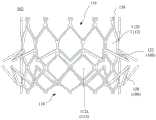
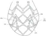
图1至图3为本申请不同实施例的心脏瓣膜置换装置的整体结构示意图。1 to 3 are schematic diagrams of the overall structure of heart valve replacement devices according to different embodiments of the present application.
图4A至图4E为本申请不同实施例的环形支撑件的结构示意图。4A to 4E are structural schematic diagrams of ring-shaped support members in different embodiments of the present application.
图5和图6为本申请不同实施例的第一夹持件与第二夹持件的结构示意图。FIG. 5 and FIG. 6 are structural schematic diagrams of the first clamping part and the second clamping part according to different embodiments of the present application.
图7A至图7C为本申请不同实施例的第一夹持单元与第二夹持单元的结构示意图。7A to 7C are structural schematic diagrams of the first clamping unit and the second clamping unit according to different embodiments of the present application.
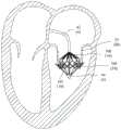
图8为本申请示例性实施例的心脏瓣膜置换装置的应用示意图。Fig. 8 is a schematic diagram of the application of the heart valve replacement device according to the exemplary embodiment of the present application.
图9为本申请示例性实施例的心脏瓣膜置换系统的应用示意图。Fig. 9 is a schematic diagram of the application of the heart valve replacement system according to the exemplary embodiment of the present application.
图10A至图10B为本申请示例性实施例的人工瓣膜锚定方法的实施示意图。FIG. 10A to FIG. 10B are schematic diagrams of the implementation of the artificial valve anchoring method according to the exemplary embodiment of the present application.
元件标号Component number
10:心脏瓣膜置换装置;10: Heart valve replacement device;
102:环形支撑件;102: ring support;
102a:内表面;102a: inner surface;
102b:外表面;102b: outer surface;
104:瓣叶结构;104: leaflet structure;
105:人工瓣叶;105: artificial leaflet;
106:第一夹持件;106: the first clamping piece;
108:第二夹持件;108: the second clamping piece;
110:支撑环;110: support ring;
112:可形变网格单元;112: deformable grid unit;
112a:四边形网格单元;112a: quadrilateral mesh unit;
112b:六边形网格单元;112b: hexagonal grid cells;
114:主体覆膜;114: main body coating;
116:流入端;116: inflow end;
118:流出端;118: outflow terminal;
120:第一夹持单元;120: the first clamping unit;
122:第二夹持单元;122: the second clamping unit;
124:固定端;124: fixed end;
126:自由端;126: free end;
128:中段部分;128: middle part;
129a/129b:驱动部;129a/129b: drive unit;
1291:穿设孔;1291: piercing holes;
130:加固单元;130: reinforcement unit;
132:锚定单元;132: anchor unit;
134:夹持覆膜;134: clamping film;
136:连接结构;136: connection structure;
20:定位装置;20: positioning device;
30:心脏;30: heart;
32:原生瓣叶;32: native leaflet;
34:原生瓣环;34: native annulus;
4:输送系统;4: Conveyor system;
42:输送外鞘;42: delivery sheath;
44:输送内鞘。44: delivering the inner sheath.
具体实施方式Detailed ways
为了使本领域的人员更好地理解本申请实施例中的技术方案,下面将结合本申请实施例中的附图,对本申请实施例中的技术方案进行清楚、完整地描述,显然,所描述的实施例仅是本申请实施例一部分实施例,而不是全部的实施例。基于本申请实施例中的实施例,本领域普通技术人员所获得的所有其他实施例,都应当属于本申请实施例保护的范围。In order to enable those skilled in the art to better understand the technical solutions in the embodiments of the present application, the following will clearly and completely describe the technical solutions in the embodiments of the present application in conjunction with the drawings in the embodiments of the present application. Obviously, the described The embodiments are only some of the embodiments of the present application, but not all of them. All other embodiments obtained by persons of ordinary skill in the art based on the embodiments in the embodiments of the present application shall fall within the protection scope of the embodiments of the present application.
目前,对于经导管二尖瓣瓣膜置换产品,大都包括冠状体结构,例如,第CN114288069A号专利、第CN114305805A号以及第CN114305806A号专利所公开的瓣膜置换结构中,均包含有用以固定瓣膜裙布的冠状体,而冠状体起到定位和密封的作用,但是冠状体的存在会引起血栓、溶血、内皮化不全等问题的风险,并且若冠状体与心脏的原生瓣环配合不到位,则会有引起置换瓣膜整体倾斜,出现瓣周漏的风险。At present, for transcatheter mitral valve replacement products, most of them include a coronary body structure. For example, in the valve replacement structures disclosed in Patent No. CN114288069A, No. CN114305805A and No. CN114305806A, all contain valve skirts for fixing The coronary body plays the role of positioning and sealing, but the existence of the coronary body will cause the risk of thrombosis, hemolysis, endothelial insufficiency and other problems, and if the coronary body does not fit in place with the original valve ring of the heart, there will be It causes the overall tilt of the replacement valve and the risk of paravalvular leakage.
有鉴于此,本申请各实施例提供一种结构改进的心脏瓣膜置换装置,以解决现有技术中存在的种种技术问题。In view of this, various embodiments of the present application provide a structurally improved heart valve replacement device to solve various technical problems existing in the prior art.
下面将结合本申请实施例附图进一步说明本申请实施例具体实现。The specific implementation of the embodiment of the present application will be further described below in conjunction with the accompanying drawings of the embodiment of the present application.
图1至图3为本申请不同实施例的心脏瓣膜置换装置10的立体结构示意图。如图所示,本实施例的心脏瓣膜置换装置10主要包括:环形支撑件102、瓣叶结构104、第一夹持件106和第二夹持件108。FIG. 1 to FIG. 3 are three-dimensional schematic diagrams of a heart
环形支撑件102具有相对设置的内表面102a和外表面102b(参考图5和图6)。The
于本实施例中,环形支撑件102可径向收缩或扩张。In this embodiment, the
具体地,通过控制环形支撑件102径向收缩,以将心脏瓣膜置换装置10收纳于输送导管内执行输送操作,并在心脏瓣膜置换装置10经由导管被输送至心脏内的指定位置后,可通过控制环形支撑件102径向扩张,以实现心脏瓣膜置换装置10在心脏内的定位。Specifically, by controlling the radial contraction of the
可选地,环形支撑件102可包括支撑环110和主体覆膜114。Optionally, the
参考图4A至图4D,支撑环110具有多个可形变网格单元112。Referring to FIGS. 4A to 4D , the
可选地,可形变网格单元112至少包括四边形网格单环112a、六边形网格单元112b中的一个,且具有相同形状的各可形变网格单元112可按行排列和/或按列排列。Optionally, the
于一实施例中,在构成环形支撑件102的各个可形变网格单元112均为四边形网格单元112a的情况下(参考图4C),或者构成环形支撑件102的各个可形变网格单元112均为六边形网格单元112b的情况下(未示出),沿环形支撑件102的径向,具有相同形状的各可形变网格单元112可为按行排列且按列排列。In one embodiment, in the case where each
于另一实施例中,在构成环形支撑件102的各个可形变网格单元同时包含有四边形网格单元112a和六边形网格单元112b的情况下(参考图4A、图4B),沿环形支撑件102的径向,具有相同形状的各个可形变网格单元112可为按行排列。In another embodiment, in the case where each deformable grid unit constituting the
主体覆膜114可贴附于支撑环110的内侧(参考图1所示实施例),或者主体覆膜114也可同时贴附于支撑环110的内侧以及外侧(参考图2所示实施例)。The
于本实施例中,主体覆膜114可由生物相容性良好的高分子覆膜制成,用于提供密封作用,以实现防止血液返流的效果。In this embodiment, the
瓣叶结构104包括沿环形支撑件102的周向,设于环形支撑件102的内表面102a的多个人工瓣叶105。例如,在图5和图6所示实施例中,瓣叶结构104包括沿环形支撑件102的周向,分布于环形支撑件102的内表面102a的三个人工瓣叶105。The
第一夹持件106和第二夹持件108,其沿环形支撑件102的轴向设于环形支撑件102的外表面102b。第一夹持件106和第二夹持件108可协同夹持心脏30的原生瓣叶32,使得瓣叶结构104相对于心脏30的原生瓣膜定位。The
可选地,第一夹持件106和第二夹持件108之间的间隔距离可介于1mm至10mm之间。Optionally, the distance between the
于本实施例中,心脏30的原生瓣叶32可被折叠堆积在第一夹持件106与第二夹持件108之间(参考图8),借以实现良好的密封作用。In this embodiment, the
于本实施例中,环形支撑件102包括沿其轴向相对设置的流入端116和流出端118(参考图1至图4)。In this embodiment, the
具体地,第一夹持件106设于环形支撑件102上接近流出端118的一侧,第二夹持件108设于环形支撑件102上接近流入端116的一侧。Specifically, the
可选地,第一夹持件106包括周向环绕环形支撑件102的外表面102b的多个第一夹持单元120,第二夹持件108包括周向环绕环形支撑件102的外表面102b的多个第二夹持单元122(参考图2至图6)。Optionally, the
于本实施例中,各第一夹持单元120与各第二夹持单元122各自包括连接环形支撑件102的固定端124、相对于固定端124的自由端126、位于固定端124和自由端126之间的中段部分128(参考图5)。In this embodiment, each
可选地,第一夹持件106的各第一夹持单元120可由环形支撑件102的外表面102b朝环形支撑件102的流入端116的方向径向向外延伸(参考图1至图3)。Optionally, each
可选地,第二夹持件108的各第二夹持单元122可由环形支撑件102的外表面102b朝环形支撑件102的流入端116的方向径向向外延伸(参考图1至图3、图4A)。于此情况下,各第一夹持单元120与各第二夹持单元122的外延伸方向为相同,即,各第一夹持单元120与各第二夹持单元122均朝环形支撑件102的流入端116的方向倾斜延伸,此结构设计可供心脏瓣膜置换装置10与附加结构(例如下述的定位装置20)协同配合,以提高心脏瓣膜置换装置10的定位效果。Optionally, each
可选地,第二夹持件108的各第二夹持单元122可由环形支撑件102的外表面102b朝环形支撑件102的流出端118的方向径向向外延伸(参考图4B、图4C)。于此情况下,各第一夹持单元120与各第二夹持单元122的外延伸方向为相反,即接近流出端118一侧的各第一夹持单元120,朝环形支撑件102的流入端116的方向倾斜延伸,接近流入端116一侧的各第二夹持单元122,朝环形支撑件102的流出端118的方向倾斜延伸,此结构设计可使得原生瓣叶32不易从第一夹持件106(第一夹持单元120)与第二夹持件(第二夹持单元122)之间脱出,减少心脏瓣膜置换装置10从原生瓣叶32上滑脱的风险,增强环形支撑件102的锚固力。Optionally, each
可选地,心脏瓣膜置换装置10还包括驱动部129a/129b(参考图7A),其可设于各第一夹持单元120与各第二夹持单元122各自的自由端126,和/或设于各第一夹持单元120与各第二夹持单元122各自的中段部分128。Optionally, the heart
其中,驱动部129a/129b可供连接驱动件(例如牵引线),并可受驱动件的作用力,控制各第一夹持单元120与各第二夹持单元122产生弹性变形,以调节各第一夹持单元120与各第二夹持单元122相对于环形支撑件102的开合角度。Wherein, the driving
于本实施例中,驱动部129a/129b可自第一夹持单元120或第二夹持单元122延伸,并具有穿设孔1291(参考图7A)。In this embodiment, the driving
其中,驱动件(例如牵引线)可穿设在驱动部129a或129b的穿设孔1291中,以使驱动部129a或129b可受驱动件的作用力,控制各第一夹持单元120或各第二夹持单元122产生不同程度的弹性变形,从而调节各第一夹持单元120与各第二夹持单元122相对于环形支撑件102的开合角度。Wherein, a driving element (such as a pulling wire) can be passed through the through
于本实施例中,驱动部129可呈I型或Y型,当驱动部129呈I型时(参考图7A的129a),驱动部129a的第一端连接在第一夹持单元120或第二夹持单元122的自由端126,穿设孔1291设于驱动部129a上的相对于第一端的第二端;当驱动部129呈Y型时(参考图7A的129b),驱动部129b的两端分别连接第一夹持单元120或第二夹持单元122的终端部分128的相对两侧。In this embodiment, the driving portion 129 can be I-shaped or Y-shaped. When the driving portion 129 is I-shaped (refer to 129a in FIG. 7A ), the first end of the driving
于其他实施例中,驱动部129a或129b也可仅包括穿设孔1291,并可开设在第一夹持单元120或第二夹持单元122的自由端126和/或中段部分128,以供穿设驱动部(参考图7B)。In other embodiments, the driving
需说明的是,驱动部和第一夹持单元120或第二夹持单元122之间的连接形态及连接位置并不以上述的实施例为限,本领域技术人员可按照实际需求进行任意调整,本申请对此不作限制。It should be noted that the connection form and connection position between the driving part and the
可选地,心脏瓣膜置换装置10还包括加固单元130,其设于各第一夹持单元120与各第二夹持单元122中的至少一个上。Optionally, the heart
例如,在图7C所示实施例中,加固单元130可设置在第一夹持单元120或第二夹持单元122的中段部分128,用于加固第一夹持单元120或第二夹持单元122的结构强度。For example, in the embodiment shown in FIG. 7C, the reinforcing
需说明的是,加固单元130的结构形态并不以图7C所示的V型结构为限,且加固单元130设置在第一夹持单元120或第二夹持单元122上的位置,也不以图7C所示的中段部分128为限,本领域技术人员可按实际需求进行任意调整,本申请对此不作限制。It should be noted that the structure of the reinforcing
可选地,心脏瓣膜置换装置10还包括锚定单元132,其设于各第一夹持单元120与各第二夹持单元122中的至少一个上。Optionally, the heart
于本实施例中,锚定单元132可为设置在第一夹持单元120或第二夹持单元122的自由端126上的倒刺(参考图4D或图4E),用于增加第一夹持单元120或第二夹持单元122对于原生瓣叶32的锚定力,使得原生瓣叶32可被牢固地夹持在第一夹持件106(第一夹持单元120)与第二夹持件108(第二夹持单元122)之间而不易滑脱。In this embodiment, the
较佳地,设于第二夹持单元122上的倒刺(锚定单元132)的尖端可朝向环形支撑件102的流出端118的方向延伸,以于第二夹持单元122被释放后,有利于设置于其上的倒刺(锚定单元132)的尖端刺入原生瓣叶32中,从而增加第二夹持单元122对于原生瓣叶32的锚定力。Preferably, the tip of the barb (anchor unit 132) provided on the
需说明的是,锚定单元132的结构形态并不以倒刺为限,此外,锚定单元132也可设置在第一夹持单元120或第二夹持单元122的中段部分128,本领域技术人员可根据实际需求做任意调整,本申请对此不作限制。It should be noted that the structural form of the
可选地,沿环形支撑件102的轴向,第一夹持件106的各第一夹持单元120与第二夹持件108的各第二夹持单元122可呈对齐设置(参考图5)或呈交错设置(参考图6)。Optionally, along the axial direction of the
可选地,第一夹持单元120或第二夹持单元122可为夹持片或夹持杆。Optionally, the
于本实施例中,在第一夹持单元120或第二夹持单元122包括夹持片的情况下(参考图4A至图4C、图4E),第一夹持单元120或第二夹持单元122可呈V型、U型、M型等。In this embodiment, when the
于本实施例中,在第一夹持单元120或第二夹持单元122包括夹持杆的情况下(参考图4D),第一夹持单元120或第二夹持单元122可呈J型、S型等。In this embodiment, in the case where the
可选地,心脏瓣膜置换装置10还包括夹持覆膜134,其设于第一夹持件106与第二夹持件108中的至少一个上(参考图1至图3)。Optionally, the heart
具体地,在图1和图2所示实施例中,在第一夹持件106与第二夹持件108的表面均贴附有夹持覆膜134;在图3所示实施例中,仅在第一夹持件106的表面贴附有夹持覆膜134。Specifically, in the embodiment shown in FIG. 1 and FIG. 2, a
于本实施例中,夹持覆膜134可包括生物相容性良好的高分子覆膜。In this embodiment, the holding
可选地,心脏瓣膜置换装置10还包括连接结构136,其设于环形支撑件102的流入端116,并可拆卸地连接外接装置(参考图4A至图4E)。Optionally, the heart
例如,可借由连接结构136,以供心脏瓣膜置换装置10与输送系统上的固定件(未示出)连接配合,以确保心脏瓣膜置换装置10在输送过程中不会发生移位。For example, the connecting
以下将配合图8、图10A、图10B,简要描述本申请应用于心脏瓣膜置换装置10的人工瓣膜锚定方法,其主要包括以下步骤:The artificial valve anchoring method applied to the heart
利用输送系统4将心脏瓣膜置换装置10输送至心脏30内。Heart
于本实施例中,输送系统4包括输送外鞘42和输送内鞘44,其中,输送内鞘上分布有固定件,可与心脏瓣膜置换装置10的环形支撑件102上的连接结构136相连接,避免心脏瓣膜置换装置在输送和释放过程中发生移位。In this embodiment, the
释放心脏瓣膜置换装置10的第一夹持件106,使得心脏30的原生瓣叶32位于心脏瓣膜置换装置10的第一夹持件106和第二夹持件108之间(参考图10A和图10B)。The
于本实施例中,心脏瓣膜置换装置10的第一夹持件106和第二夹持件108可借由驱动部129a/129b连接驱动件(例如牵引线),且驱动件与输送内鞘的端部相连接,可借由驱动件向第一夹持件106和第二夹持件108施加作用力,以调整第一夹持件106中各第一夹持单元120与第二夹持件108中各第二夹持单元122相对于环形支撑件102的开合角度。In this embodiment, the
具体地,可经由驱动件(例如牵引线)释放接近流出端118的第一夹持件106,同时增大输送系统4的输送内鞘的端部和环形支撑件102的流出端之间的间距,使得第一夹持件106的张开角度增大,从而便于将原生瓣叶32的游离缘捕捉到第一夹持件106和环形支撑件102之间。Specifically, the
控制心脏瓣膜置换装置10相对于心脏30移动,使得原生瓣叶32在心脏瓣膜置换装置10的第一夹持体和环形支撑件102之间折叠。The heart
具体地,可将心脏瓣膜置换装置10整体向上提拉,使得原生瓣叶32在第一夹持件106和环形支撑件102之间的空间内折叠。Specifically, the heart
释放心脏瓣膜置换装置10的第二夹持件108,使得第一夹持件106和第二夹持件108协同配合,以夹持原生瓣叶32,并使心脏瓣膜置换装置10相对于心脏30的原生瓣膜定位。Release the
具体地,可经由驱动件(例如牵引线)释放接近流入端116的第二夹持件108,使得第二夹持件108恢复至原始的张开状态,借以将折叠的原生瓣叶32夹持在第一夹持件106和第二夹持件108之间,从而实现环形支撑件102在原生瓣叶32处的固定。Specifically, the
可选地,可在释放心脏瓣膜置换装置10的第二夹持件108的同时,释放心脏瓣膜置换装置10的环形支撑件102,以使其径向扩张;或者,也在释放心脏瓣膜置换装置10的第二夹持件108之后,再释放心脏瓣膜置换装置10的环形支撑件102,以使其径向扩张。Optionally, the
借此,本实施例所提供的用于心脏瓣膜置换装置10的人工瓣膜锚定方法,可供折叠的原生瓣叶夹持在第一夹持件与第二夹持件之间形成三明治的夹持效果,以实现环形支撑件在原生瓣叶上的固定,且通过原生瓣叶的折叠堆积以及支撑环、第一夹持件、第二夹持件上的覆膜,实现良好的密封效果。In this way, the artificial valve anchoring method used in the heart
本申请另一实施例提供一种心脏瓣膜置换系统,其包括心脏瓣膜置换装置10和定位装置20(参考图9)。Another embodiment of the present application provides a heart valve replacement system, which includes a heart
心脏瓣膜置换装置10的结构设计可参考上述图1至图8所示实施例的描述,在此不予赘述。For the structural design of the heart
定位装置20可定位于心脏瓣膜置换装置10的第一夹持件106和第二夹持件108之间,并定位于心脏30的指定位置,以使心脏瓣膜置换装置10相对于心脏30的原生瓣膜固定。The
可选地,定位装置20可包括定位在心室的心室部分,或者定位装置20可同时包括定位在心室的心室部分以及定位在心房的心房部分。Alternatively, the
综上所述,本申请实施例所提供的心脏瓣膜置换系统,借由心脏瓣膜置换装置10和定位装置20之间的联合作用,可进一步提高心脏瓣膜置换装置10相对于心脏的定位效果,并可增加密封性,提高人工心脏瓣膜置换效果。To sum up, the heart valve replacement system provided by the embodiment of the present application can further improve the positioning effect of the heart
以下将参考图9,简要描述本申请应用于心脏瓣膜置换系统的人工瓣膜锚定方法,其主要包括以下步骤:The artificial valve anchoring method applied to the heart valve replacement system of the present application will be briefly described below with reference to FIG. 9 , which mainly includes the following steps:
利用输送系统4将心脏瓣膜置换系统的定位装置20输送至心脏30内,以使定位装置20定位于心脏30内的指定位置,并将心脏30的各原生瓣叶32于定位装置20中。The
具体地,定位装置20可包括心房部分和心室部分,其中,心房部分和心室部分可相互连接为一个整体,定位装置20的心房部分可包括半环结构,并可固定在心脏30的原生瓣环34处,从而实现定位装置20在原生瓣膜处的固定,定位装置20的心室部分可包括封闭环结构,用于将心脏30的原生瓣叶32收拢在封闭环结构的内部。Specifically, the
利用输送系统4(参考图10A)将心脏瓣膜置换装置10输送至定位装置20的内部,并依次释放心脏瓣膜置换装置10的第一夹持件106和第二夹持体,以将心脏30的各原生瓣叶32夹持在心脏瓣膜置换装置10的第一夹持件106、第二夹持件108以及定位装置20之间,以使心脏瓣膜置换系统相对于心脏30的原生瓣膜32定位。Use the delivery system 4 (refer to FIG. 10A ) to deliver the heart
于本实施例中,利用心脏瓣膜置换装置10夹持心脏30的各原生瓣叶32的具体步骤可参考上述应用于心脏瓣膜置换装置10的人工瓣膜锚定方法,在此不予赘述。In this embodiment, the specific steps of using the heart
综上所述,本实施例所提供的应用于心脏瓣膜置换系统的人工瓣膜锚定方法,利用原生瓣叶在定位装置(封闭环结构)周围的堆积包覆,以及定位装置(封闭环结构)与心脏瓣膜置换装置的环形支撑件之间的径向相互作用力,可在实现良好密封效果的同时,亦有效提高了心脏瓣膜置换装置在原生瓣膜处的锚定力。In summary, the artificial valve anchoring method applied to the heart valve replacement system provided by this embodiment utilizes the accumulation and coating of the original valve leaflets around the positioning device (closed ring structure), and the positioning device (closed ring structure) The radial interaction force with the annular support member of the heart valve replacement device can effectively improve the anchoring force of the heart valve replacement device at the original valve while achieving a good sealing effect.
最后应说明的是:以上实施例仅用以说明本申请实施例的技术方案,而非对其限制;尽管参照前述实施例对本申请进行了详细的说明,本领域的普通技术人员应当理解:其依然可以对前述各实施例所记载的技术方案进行修改,或者对其中部分技术特征进行等同替换;而这些修改或者替换,并不使相应技术方案的本质脱离本申请各实施例技术方案的精神和范围。Finally, it should be noted that: the above embodiments are only used to illustrate the technical solutions of the embodiments of the present application, and are not intended to limit them; although the application has been described in detail with reference to the foregoing embodiments, those of ordinary skill in the art should understand that: It is still possible to modify the technical solutions described in the foregoing embodiments, or perform equivalent replacements for some of the technical features; and these modifications or replacements do not make the essence of the corresponding technical solutions deviate from the spirit and spirit of the technical solutions of the various embodiments of the present application. scope.
Claims (16)
Priority Applications (1)
| Application Number | Priority Date | Filing Date | Title |
|---|---|---|---|
| CN202211606675.1ACN116236319A (en) | 2022-12-13 | 2022-12-13 | Heart valve replacement device, system, and artificial valve anchoring method |
Applications Claiming Priority (1)
| Application Number | Priority Date | Filing Date | Title |
|---|---|---|---|
| CN202211606675.1ACN116236319A (en) | 2022-12-13 | 2022-12-13 | Heart valve replacement device, system, and artificial valve anchoring method |
Publications (1)
| Publication Number | Publication Date |
|---|---|
| CN116236319Atrue CN116236319A (en) | 2023-06-09 |
Family
ID=86633902
Family Applications (1)
| Application Number | Title | Priority Date | Filing Date |
|---|---|---|---|
| CN202211606675.1APendingCN116236319A (en) | 2022-12-13 | 2022-12-13 | Heart valve replacement device, system, and artificial valve anchoring method |
Country Status (1)
| Country | Link |
|---|---|
| CN (1) | CN116236319A (en) |
Citations (9)
| Publication number | Priority date | Publication date | Assignee | Title |
|---|---|---|---|---|
| US20120078353A1 (en)* | 2010-09-23 | 2012-03-29 | Cardiaq Valve Technologies, Inc. | Replacement heart valves, delivery devices and methods |
| US20150351904A1 (en)* | 2014-06-06 | 2015-12-10 | Edwards Lifesciences Corporation | Prosthetic valve for replacing a mitral valve |
| CN105188611A (en)* | 2013-02-04 | 2015-12-23 | 爱德华兹生命科学公司 | Prosthetic valve for replacing mitral valve |
| US20190262129A1 (en)* | 2018-02-28 | 2019-08-29 | Edwards Lifesciences Corporation | Prosthetic mitral valve with improved anchors and seal |
| CN112754732A (en)* | 2021-01-20 | 2021-05-07 | 上海纽脉医疗科技有限公司 | Interventional artificial heart valve and medical device |
| CN113730032A (en)* | 2020-05-28 | 2021-12-03 | 爱德华兹生命科学公司 | Methods and devices for leaflet folding or capturing |
| CN215458984U (en)* | 2021-04-30 | 2022-01-11 | 沛嘉医疗科技(苏州)有限公司 | Valve stent and prosthetic valve assembly |
| CN114469444A (en)* | 2020-11-12 | 2022-05-13 | 沛嘉医疗科技(苏州)有限公司 | Valve stents and valve prostheses |
| CN114848233A (en)* | 2022-05-05 | 2022-08-05 | 上海汇禾医疗科技有限公司 | Prosthetic valve assembly, implantation system and implantation method |
- 2022
- 2022-12-13CNCN202211606675.1Apatent/CN116236319A/enactivePending
Patent Citations (9)
| Publication number | Priority date | Publication date | Assignee | Title |
|---|---|---|---|---|
| US20120078353A1 (en)* | 2010-09-23 | 2012-03-29 | Cardiaq Valve Technologies, Inc. | Replacement heart valves, delivery devices and methods |
| CN105188611A (en)* | 2013-02-04 | 2015-12-23 | 爱德华兹生命科学公司 | Prosthetic valve for replacing mitral valve |
| US20150351904A1 (en)* | 2014-06-06 | 2015-12-10 | Edwards Lifesciences Corporation | Prosthetic valve for replacing a mitral valve |
| US20190262129A1 (en)* | 2018-02-28 | 2019-08-29 | Edwards Lifesciences Corporation | Prosthetic mitral valve with improved anchors and seal |
| CN113730032A (en)* | 2020-05-28 | 2021-12-03 | 爱德华兹生命科学公司 | Methods and devices for leaflet folding or capturing |
| CN114469444A (en)* | 2020-11-12 | 2022-05-13 | 沛嘉医疗科技(苏州)有限公司 | Valve stents and valve prostheses |
| CN112754732A (en)* | 2021-01-20 | 2021-05-07 | 上海纽脉医疗科技有限公司 | Interventional artificial heart valve and medical device |
| CN215458984U (en)* | 2021-04-30 | 2022-01-11 | 沛嘉医疗科技(苏州)有限公司 | Valve stent and prosthetic valve assembly |
| CN114848233A (en)* | 2022-05-05 | 2022-08-05 | 上海汇禾医疗科技有限公司 | Prosthetic valve assembly, implantation system and implantation method |
Similar Documents
| Publication | Publication Date | Title |
|---|---|---|
| CN108261258B (en) | Valve prostheses and delivery methods | |
| CN107405197B (en) | Valve prosthesis with integrated centering mechanism and method of use thereof | |
| CN107106297B (en) | Heart valve prosthesis | |
| JP2023520437A (en) | Highly Flexible Implant Catheter with Low Compressibility | |
| US10022222B2 (en) | Systems and methods for treating lumenal valves | |
| US20190060070A1 (en) | Systems and methods for treating lumenal valves | |
| JP2018533455A (en) | Mitral valve prosthesis | |
| US11771557B2 (en) | Apparatus and method to reshape geometry of diseased heart valve | |
| WO2019128583A1 (en) | Cardiac valve prosthesis and stent thereof | |
| US12102532B2 (en) | Systems and methods for treating luminal valves | |
| WO2023155538A1 (en) | Anchoring devices of artificial heart valve and artificial heart valve system | |
| CN117159228B (en) | A valve prosthesis device with segmented conical structure | |
| CN112399833B (en) | Systems, methods, and devices for treating tricuspid insufficiency | |
| CN117100458A (en) | Valve prosthesis device with selectively distributed barbs | |
| WO2022267851A1 (en) | Repair device for preventing valve regurgitation | |
| CN114848233A (en) | Prosthetic valve assembly, implantation system and implantation method | |
| CN116236319A (en) | Heart valve replacement device, system, and artificial valve anchoring method | |
| CN117562708A (en) | Stents for valve devices, valve devices and delivery systems | |
| CN117137683A (en) | Anchor stents, cardiac valve regurgitation replacement components and anchor stent delivery devices | |
| CN115844592A (en) | Heart valve positioning device, artificial heart valve system, implantation system and method | |
| CN115737207A (en) | Heart valve positioning device, artificial valve system and implantation method thereof | |
| CN116807688B (en) | Valve stent and valve device | |
| CN221904223U (en) | Anchoring stent for heart valve replacement system | |
| US20200352715A1 (en) | Systems and methods for treating luminal valves | |
| WO2023197328A1 (en) | Aortic valve stent and system for conveying aortic valve stent |
Legal Events
| Date | Code | Title | Description |
|---|---|---|---|
| PB01 | Publication | ||
| PB01 | Publication | ||
| SE01 | Entry into force of request for substantive examination | ||
| SE01 | Entry into force of request for substantive examination |