CN116234351A - Display panel, manufacturing method thereof, display module and display device - Google Patents
Display panel, manufacturing method thereof, display module and display deviceDownload PDFInfo
- Publication number
- CN116234351A CN116234351ACN202310322998.6ACN202310322998ACN116234351ACN 116234351 ACN116234351 ACN 116234351ACN 202310322998 ACN202310322998 ACN 202310322998ACN 116234351 ACN116234351 ACN 116234351A
- Authority
- CN
- China
- Prior art keywords
- layer
- area
- display panel
- display
- substrate
- Prior art date
- Legal status (The legal status is an assumption and is not a legal conclusion. Google has not performed a legal analysis and makes no representation as to the accuracy of the status listed.)
- Pending
Links
Images


Classifications
- G—PHYSICS
- G09—EDUCATION; CRYPTOGRAPHY; DISPLAY; ADVERTISING; SEALS
- G09F—DISPLAYING; ADVERTISING; SIGNS; LABELS OR NAME-PLATES; SEALS
- G09F9/00—Indicating arrangements for variable information in which the information is built-up on a support by selection or combination of individual elements
- G09F9/30—Indicating arrangements for variable information in which the information is built-up on a support by selection or combination of individual elements in which the desired character or characters are formed by combining individual elements
- G09F9/33—Indicating arrangements for variable information in which the information is built-up on a support by selection or combination of individual elements in which the desired character or characters are formed by combining individual elements being semiconductor devices, e.g. diodes
- G09F9/335—Indicating arrangements for variable information in which the information is built-up on a support by selection or combination of individual elements in which the desired character or characters are formed by combining individual elements being semiconductor devices, e.g. diodes being organic light emitting diodes [OLED]
- G—PHYSICS
- G09—EDUCATION; CRYPTOGRAPHY; DISPLAY; ADVERTISING; SEALS
- G09F—DISPLAYING; ADVERTISING; SIGNS; LABELS OR NAME-PLATES; SEALS
- G09F9/00—Indicating arrangements for variable information in which the information is built-up on a support by selection or combination of individual elements
- G09F9/30—Indicating arrangements for variable information in which the information is built-up on a support by selection or combination of individual elements in which the desired character or characters are formed by combining individual elements
- G09F9/301—Indicating arrangements for variable information in which the information is built-up on a support by selection or combination of individual elements in which the desired character or characters are formed by combining individual elements flexible foldable or roll-able electronic displays, e.g. thin LCD, OLED
- Y—GENERAL TAGGING OF NEW TECHNOLOGICAL DEVELOPMENTS; GENERAL TAGGING OF CROSS-SECTIONAL TECHNOLOGIES SPANNING OVER SEVERAL SECTIONS OF THE IPC; TECHNICAL SUBJECTS COVERED BY FORMER USPC CROSS-REFERENCE ART COLLECTIONS [XRACs] AND DIGESTS
- Y02—TECHNOLOGIES OR APPLICATIONS FOR MITIGATION OR ADAPTATION AGAINST CLIMATE CHANGE
- Y02E—REDUCTION OF GREENHOUSE GAS [GHG] EMISSIONS, RELATED TO ENERGY GENERATION, TRANSMISSION OR DISTRIBUTION
- Y02E10/00—Energy generation through renewable energy sources
- Y02E10/50—Photovoltaic [PV] energy
- Y02E10/549—Organic PV cells
Landscapes
- Physics & Mathematics (AREA)
- Engineering & Computer Science (AREA)
- General Physics & Mathematics (AREA)
- Theoretical Computer Science (AREA)
- Microelectronics & Electronic Packaging (AREA)
- Optics & Photonics (AREA)
- Devices For Indicating Variable Information By Combining Individual Elements (AREA)
Abstract
Translated fromChinese
Description
Translated fromChinese技术领域technical field
本申请涉及显示技术领域,具体涉及一种显示面板及其制备方法、显示模组和显示装置。The present application relates to the field of display technology, in particular to a display panel and a manufacturing method thereof, a display module and a display device.
背景技术Background technique
柔性显示面板通常以聚酰亚胺薄膜为衬底,将驱动芯片绑定在聚酰亚胺薄膜上(Chip On Pi,COP)的工艺,使得柔性显示面板的邦定区可以弯折到非显示侧,从而实现了窄边框。然而,随着消费者对窄边框需求的不断提升,如何进一步减小边框宽度,一直是本领域技术人员不断研究的课题。Flexible display panels are usually based on polyimide film, and the driver chip is bound to the polyimide film (Chip On Pi, COP) process, so that the bonding area of the flexible display panel can be bent to the non-display side, thereby achieving narrow bezels. However, as consumers' demand for narrow bezels continues to increase, how to further reduce the width of the bezels has always been a subject of continuous research by those skilled in the art.
发明内容Contents of the invention
有鉴于此,本申请实施例提供了一种显示面板及其制备方法、显示模组和显示装置,以解决现有技术中如何进一步实现窄边框的问题。In view of this, the embodiments of the present application provide a display panel and a manufacturing method thereof, a display module and a display device, so as to solve the problem of how to further realize narrow borders in the prior art.
本申请第一方面提供了一种显示面板,具有边框区和位于边框区一侧的弯折区。显示面板包括:基板,包括金属走线和挡墙,金属走线位于边框区,并延伸至弯折区,挡墙位于边框区,与金属走线叠置;封装层,与基板叠置,并终止于挡墙的靠近弯折区的一侧;支撑层,叠置在弯折区的金属走线的远离基板的一侧,与封装层接触;以及阻隔层,叠置在支撑层的远离金属走线的一侧。通过利用支撑层和阻隔层的组合代替常规的胶层。其中,支撑层可以起到支撑作用,阻隔层可以起到阻隔水和氧气的作用。在相同支撑力和水氧阻隔能力的前提下,支撑层和阻隔层组合后的膜层厚度小于胶层的厚度,从而缩小了弯折区的弯折半径,进一步实现了窄边框。The first aspect of the present application provides a display panel, which has a frame area and a bending area located on one side of the frame area. The display panel includes: a substrate, including metal wiring and a barrier wall, the metal wiring is located in the frame area and extends to the bending area, and the barrier wall is located in the frame area and overlaps with the metal wiring; an encapsulation layer overlaps with the substrate, and Terminated on the side of the barrier wall near the bend area; the support layer, which is stacked on the side of the metal trace in the bend area away from the substrate, is in contact with the packaging layer; and the barrier layer is stacked on the side of the support layer away from the metal trace. side of the line. By utilizing a combination of support layer and barrier layer instead of the conventional glue layer. Wherein, the support layer can play a supporting role, and the barrier layer can play a role of blocking water and oxygen. Under the premise of the same support force and water and oxygen barrier capacity, the thickness of the film layer after the combination of the support layer and the barrier layer is smaller than the thickness of the adhesive layer, thereby reducing the bending radius of the bending area and further realizing a narrow frame.
结合第一方面,在一些实施方式中,显示面板还包括堤坝,位于弯折区,与金属走线叠置,堤坝环绕支撑层的至少部分边缘,位于堤坝和挡墙之间的金属走线呈弯曲状。支撑层可以采用喷墨打印工艺制备,为了避免打印材料溢出弯折区之外,可以在弯折区的周边设置堤坝,以阻挡打印材料,避免外溢。With reference to the first aspect, in some implementations, the display panel further includes a dam located in the bending area and overlapping with the metal wiring, the dam surrounds at least part of the edge of the supporting layer, and the metal wiring between the dam and the retaining wall is in the form of Curved. The support layer can be prepared by inkjet printing process. In order to prevent the printing material from overflowing beyond the bending area, a dam can be set around the bending area to block the printing material and avoid overflow.
结合第一方面,在一些实施方式中,阻隔层与封装层接触,阻隔层在基板上的正投影覆盖至少部分挡墙。这样的好处在于,利用阻隔层补偿边框区和弯折区之间的至少部分高度差,后续在显示面板的显示侧贴附偏光片时,可以减小偏光片边缘和封装层边缘之间填充的胶层厚度,从而降低发生光干涉的概率,进而减少漏光风险,提升显示效果。With reference to the first aspect, in some implementations, the barrier layer is in contact with the encapsulation layer, and the orthographic projection of the barrier layer on the substrate covers at least part of the barrier wall. The advantage of this is that at least part of the height difference between the frame area and the bending area is compensated by using the barrier layer, and the filling gap between the edge of the polarizer and the edge of the encapsulation layer can be reduced when the polarizer is subsequently attached to the display side of the display panel. The thickness of the glue layer can reduce the probability of light interference, thereby reducing the risk of light leakage and improving the display effect.
结合第一方面,在一些实施方式中,显示面板还包括防静电层,防静电层叠置在阻隔层的远离支撑层的一侧,防静电层在基板上的正投影覆盖边框区的至少部分封装层。利用支撑层、阻隔层和防静电层的组合代替常规的胶层,可以使弯折区的厚度至小,从而利于实现窄边框,并且增加了静电释放功能。In combination with the first aspect, in some embodiments, the display panel further includes an antistatic layer, the antistatic layer is stacked on the side of the barrier layer away from the support layer, and the orthographic projection of the antistatic layer on the substrate covers at least part of the encapsulation of the frame area layer. Using the combination of support layer, barrier layer and antistatic layer to replace the conventional adhesive layer can minimize the thickness of the bending area, thereby facilitating the realization of a narrow frame and increasing the electrostatic discharge function.
结合第一方面,在一些实施方式中,防静电层包括至少一条金属线,金属线由边框区指向弯折区。通过将防静电层实施为至少一条金属线,相比于整层金属层而言,可以节省金属材料,同时提升柔性,更易于弯折。With reference to the first aspect, in some embodiments, the antistatic layer includes at least one metal wire, and the metal wire is directed from the frame area to the bending area. By implementing the antistatic layer as at least one metal wire, compared with the entire metal layer, metal material can be saved, while improving flexibility and making it easier to bend.
本申请第二方面提供了一种显示模组,包括上述任一实施例提供的显示面板。The second aspect of the present application provides a display module, including the display panel provided by any one of the above embodiments.
结合第二方面,在一些实施方式中,还包括至少一个功能膜片,叠置在显示面板的显示侧;显示面板包括防静电层,叠置在阻隔层的远离支撑层的一侧,并与至少一个功能膜片接触。防静电层可以将至少一个功能膜片中的静电荷导出,避免静电荷击穿显示面板。In conjunction with the second aspect, in some embodiments, at least one functional film is also included, stacked on the display side of the display panel; the display panel includes an antistatic layer, stacked on the side of the barrier layer away from the support layer, and At least one functional diaphragm is in contact. The antistatic layer can lead out the static charge in at least one functional film, so as to prevent the static charge from breaking down the display panel.
结合第二方面,在一些实施方式中,显示模组还包括绝缘胶带,覆盖防静电层的至少部分区域;绝缘胶带包括露铜区,露铜区与防静电层接触。利于绝缘胶带释放防静电层41中的静电荷,兼容现有技术。With reference to the second aspect, in some embodiments, the display module further includes an insulating tape covering at least a part of the antistatic layer; the insulating tape includes a copper exposed area, and the exposed copper area is in contact with the antistatic layer. It is beneficial for the insulating tape to release the static charge in the antistatic layer 41, and is compatible with the prior art.
本申请第三方面提供了一种显示面板的制备方法,显示面板具有边框区和位于边框区一侧的弯折区,制备方法包括:基板包括金属走线和挡墙,金属走线位于边框区,并延伸至弯折区,挡墙位于边框区,与金属走线叠置,封装层从边框区延伸并终止于挡墙的靠近弯折区的一侧;在弯折区的金属走线上制备支撑层,支撑层与封装层接触;在支撑层上制备阻隔层,得到显示面板。The third aspect of the present application provides a method for preparing a display panel. The display panel has a frame area and a bending area located on one side of the frame area. The preparation method includes: the substrate includes metal wiring and a retaining wall, and the metal wiring is located in the frame area. , and extend to the bending area, the retaining wall is located in the frame area, overlapping with the metal trace, the encapsulation layer extends from the frame area and terminates at the side of the retaining wall close to the bending area; on the metal trace in the bending area A support layer is prepared, and the support layer is in contact with the encapsulation layer; a barrier layer is prepared on the support layer to obtain a display panel.
本申请第四方面提供了一种显示装置,包括上述任一实施例提供的显示模组。A fourth aspect of the present application provides a display device, including the display module provided in any one of the above embodiments.
根据本申请实施例提供的显示面板及其制备方法、显示模组和显示装置,显示面板包括基板,包括金属走线和挡墙,金属走线位于边框区,并延伸至弯折区,挡墙位于边框区,与金属走线叠置;封装层,与基板叠置,并终止于挡墙的靠近弯折区的一侧;支撑层,叠置在弯折区的金属走线的远离基板的一侧,与封装层接触;以及阻隔层,叠置在支撑层的远离金属走线的一侧。通过利用支撑层和阻隔层的组合代替常规的胶层。其中,支撑层可以起到支撑作用,阻隔层可以起到阻隔水和氧气的作用。在相同支撑力和水氧阻隔能力的前提下,支撑层和阻隔层组合后的膜层厚度小于胶层的厚度,从而缩小了弯折区的弯折半径,进一步实现了窄边框。According to the display panel and its preparation method, display module and display device provided by the embodiments of the present application, the display panel includes a substrate, including metal wiring and a retaining wall, the metal wiring is located in the frame area and extends to the bending area, and the retaining wall Located in the border area, overlapping with the metal traces; the packaging layer, overlapping with the substrate, and terminated on the side of the barrier wall close to the bending area; the supporting layer, overlapping the metal traces in the bending area away from the substrate One side is in contact with the encapsulation layer; and the barrier layer is stacked on the side of the support layer away from the metal traces. By utilizing a combination of support layer and barrier layer instead of the conventional glue layer. Wherein, the support layer can play a supporting role, and the barrier layer can play a role of blocking water and oxygen. Under the premise of the same support force and water and oxygen barrier capacity, the thickness of the film layer after the combination of the support layer and the barrier layer is smaller than the thickness of the adhesive layer, thereby reducing the bending radius of the bending area and further realizing a narrow frame.
附图说明Description of drawings
图1为相关技术中的显示面板的结构示意图。FIG. 1 is a schematic structural diagram of a display panel in the related art.
图2为本申请第一实施例提供的显示面板的结构示意图。FIG. 2 is a schematic structural diagram of a display panel provided by the first embodiment of the present application.
图3为本申请第二实施例提供的显示面板的结构示意图。FIG. 3 is a schematic structural diagram of a display panel provided by a second embodiment of the present application.
图4为本申请第三实施例提供的显示面板的结构示意图。FIG. 4 is a schematic structural diagram of a display panel provided by a third embodiment of the present application.
图5为图4所示显示面板的局部俯视图。FIG. 5 is a partial top view of the display panel shown in FIG. 4 .
图6为本申请一实施例提供的显示模组的结构示意图。FIG. 6 is a schematic structural diagram of a display module provided by an embodiment of the present application.
图7为本申请一实施例提供的显示面板的制备方法的流程示意图。FIG. 7 is a schematic flowchart of a method for manufacturing a display panel provided by an embodiment of the present application.
图8为本申请一实施例提供的显示装置的结构示意图。FIG. 8 is a schematic structural diagram of a display device provided by an embodiment of the present application.
具体实施方式Detailed ways
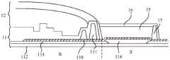
图1为相关技术中的显示面板的结构示意图。如图1所示,显示面板具有显示区AA和环绕显示区AA的非显示区,非显示区包括边框区B和弯折区S,弯折区S位于边框区B的远离显示区AA的一侧。FIG. 1 is a schematic structural diagram of a display panel in the related art. As shown in FIG. 1, the display panel has a display area AA and a non-display area surrounding the display area AA. The non-display area includes a frame area B and a bending area S. The bending area S is located at a side of the frame area B away from the display area AA. side.
显示面板包括基板11、封装层12和胶层13。其中,封装层12位于显示区AA和边框区B,与基板11叠置。基板11为发光基板,包括依次叠置的衬底、TFT阵列层、发光器件层。发光器件层位于显示区AA。TFT阵列层包括叠置的多个金属层,至少一个金属层中的金属走线110在平行于衬底的方向上,向远离显示区AA的方向延伸至弯折区S,形成裸露区域。胶层13叠置在弯折区S的金属走线110的远离衬底的一侧,以覆盖金属走线110的至少部分裸露区域。胶层13可以起到一定的支撑作用,同时可以阻隔水和氧气。The display panel includes a
胶层13上开设有暴露金属走线110的凹槽,金属走线110通过凹槽暴露,以和驱动芯片14电连接。对弯折区S进行弯折,可以将驱动芯片14定位在显示面板的非显示侧,从而实现窄边框。The
图1所示的显示面板,对弯折区S进行弯折的过程中,弯折区S会产生弯折应力。为了避免弯折应力对金属走线110造成损伤,需要合理设置胶层13的厚度,以确保弯折中性面位于金属走线110中。这种情况下,胶层13的厚度一般在100微米左右。胶层13的厚度对弯折区S的弯折半径造成了限制,进而使边框区B的尺寸无法进一步缩小。In the display panel shown in FIG. 1 , during the bending process of the bending region S, the bending region S will generate bending stress. In order to prevent the bending stress from causing damage to the
有鉴于此,本申请实施例提供了一种显示面板及其制备方法、显示模组和显示装置,利用支撑层和阻隔层的组合代替胶层13。其中,支撑层可以起到支撑作用,阻隔层可以起到阻隔水和氧气的作用。在相同支撑力和水氧阻隔能力的前提下,支撑层和阻隔层组合后的膜层厚度小于胶层13的厚度,从而缩小了弯折区的弯折半径,进一步实现了窄边框。In view of this, the embodiments of the present application provide a display panel and a manufacturing method thereof, a display module and a display device, in which the
下面将结合本申请实施例中的附图,对本申请实施例中的技术方案进行清楚、完整地描述,显然,所描述的实施例仅是本申请一部分实施例,而不是全部的实施例。基于本申请中的实施例,本领域普通技术人员在没有做出创造性劳动前提下所获得的所有其他实施例,都属于本申请保护的范围。The following will clearly and completely describe the technical solutions in the embodiments of the application with reference to the drawings in the embodiments of the application. Apparently, the described embodiments are only some, not all, embodiments of the application. Based on the embodiments in this application, all other embodiments obtained by persons of ordinary skill in the art without making creative efforts belong to the scope of protection of this application.
图2为本申请第一实施例提供的显示面板的结构示意图。如图2所示,显示面板具有边框区B和位于边框区B一侧的弯折区S。边框区B环绕显示区(图2中未示出),弯折区S位于边框区B的远离显示区的一侧。FIG. 2 is a schematic structural diagram of a display panel provided by the first embodiment of the present application. As shown in FIG. 2 , the display panel has a frame area B and a bending area S located on one side of the frame area B. As shown in FIG. The frame area B surrounds the display area (not shown in FIG. 2 ), and the bending area S is located on a side of the frame area B away from the display area.
显示面板包括:基板11、封装层12、支撑层15和阻隔层16。The display panel includes: a
其中,基板11包括金属走线110和挡墙111。金属走线110位于边框区B,并延伸至弯折区S。挡墙111位于边框区B,与金属走线110叠置。挡墙111用于对封装层12进行限位,以将封装层限制在边框区B范围内,保证封装效果。Wherein, the
具体而言,基板11为发光基板,包括依次叠置的衬底112、TFT阵列层和发光器件层(图中未示出)。基板11还可以包括缓冲层113和填充层114,缓冲层位于衬底112和TFT阵列层之间,弯折区S的缓冲层113上开设有通孔,通孔内填充有填充层114。衬底112的材料可以是聚酰亚胺,缓冲层的材料可以是氮化硅、氧化硅、氧化铝、氧化镁等。TFT阵列层包括多个金属层,至少一个金属层中的金属走线110从边框区B延伸至弯折区S。金属走线110例如可以是扫描信号线、数据信号线、参考电压信号线中的至少一项。金属走线110从显示区延伸至弯折区S,以在弯折区S的远离显示区的一端形成金手指,用于与驱动芯片电连接,用于接收或输出电信号。Specifically, the
封装层12与基板11叠置,并终止于挡墙111的靠近弯折区S的一侧。这种情况下,边框区B的金属走线110可以被封装层12覆盖,弯折区S的金属走线110形成裸露区域。The
支撑层15叠置在弯折区S的金属走线110的远离基板11的一侧。支撑层15用于在弯折区S起支撑作用。支撑层15背离金属走线110的表面为平面。支撑层15的厚度大于或等于8微米,并且小于或等于5微米。例如,支撑层15最厚的区域的厚度可以设置为8微米,最薄的区域的厚度可以设置为5微米。支撑层15固化后的模量大约为1Gpa。支撑层15的材料可以是改性丙烯酸高分子材料,或固化后具有大致相同模量的其它材料。The supporting
值得说明的是,本实施例中的支撑层与挡墙111侧壁上的封装层12接触。It is worth noting that the support layer in this embodiment is in contact with the
如图2所示的显示面板还可以包括堤坝17,位于弯折区S,与金属走线110叠置,堤坝17环绕支撑层15的至少部分边缘,位于堤坝17和挡墙111之间的金属走线110呈弯曲状,弯曲状的金属走线110可以在弯折区S弯折过程中释放弯折应力。堤坝17在垂直于显示面板的方向上的高度大于支撑层50的厚度。堤坝17可以和挡墙111配合形成环形凹槽结构,即挡墙111进一步起到对支撑层15进行限位的作用。The display panel shown in FIG. 2 may also include a dam 17 located in the bending area S and overlapping with the
阻隔层16叠置在支撑层15的远离金属走线110的一侧。阻隔层16在基板11上的正投影覆盖部分封装层12、支撑层15和堤坝17。阻隔层16的第一侧与覆盖挡墙111侧壁的封装层12接触,阻隔层16的第二侧终止于堤坝17的远离挡墙111的一侧,第一侧和第二侧相对设置,即阻隔层16包覆堤坝17的远离挡墙111的侧壁。阻隔层16为耐腐蚀层,具有疏水疏油,耐酸耐碱的特性。阻隔层16的材料可以是氟化物高分子材料。阻隔层16的远离支撑层15的表面为平面。阻隔层16在垂直于显示面板方向上的厚度大于或等于5微米,并且小于或等于20微米。可见,阻隔层16和支撑层15组合后的最大厚度为28微米,而图1所示显示面板中的胶层14的厚度为100微米左右,比较而言,利用阻隔层16和支撑层15的组合取代胶层14可以极大地减小弯折区S的膜层厚度,从而进一步实现窄边框。The
支撑层15可以采用喷墨打印工艺制备,为了避免打印材料溢出弯折区S之外,可以在弯折区S的周边设置堤坝17,以阻挡打印材料,避免外溢。在一示例中,堤坝17的材料和支撑层15的材料相同。这种情况下,可以调整相关工艺参数,使得制备堤坝17时的打印材料的粘稠性相对较高,以形成凸起结构的堤坝17;使得制备支撑层15时的打印材料的粘稠性相对较低,以在堤坝17圈出的范围内流平,形成具有平坦表面的支撑层15。The supporting
图3为本申请第二实施例提供的显示面板的结构示意图。对比图3和图2所示显示面板可知,图3所示显示面板和图2所示显示面板的区别在于,图3所示显示面板中的阻隔层16在基板11上的正投影覆盖至少部分挡墙111。在一示例中,阻隔层16和封装层12各自远离基板11的表面共平面。这样的好处在于,利用阻隔层16补偿弯折区S和边框区B之间的至少部分高度差,后续在显示面板的显示侧贴附偏光片时,无需利用胶层或只需利用较薄的胶层来填充偏光片与边框区B和弯折区S之间过渡区之间的间隙,从而降低发生光干涉现象的概率,进而降低漏光风险,提升显示效果。FIG. 3 is a schematic structural diagram of a display panel provided by a second embodiment of the present application. Comparing the display panels shown in FIG. 3 and FIG. 2, it can be seen that the difference between the display panel shown in FIG. 3 and the display panel shown in FIG. 2 is that the orthographic projection of the
图4为本申请第三实施例提供的显示面板的结构示意图。对比图4和图2、图3所示显示面板可知,图4所示显示面板还包括防静电层18。防静电层18叠置在阻隔层16的远离支撑层15的一侧。防静电层18在基板11上的正投影覆盖边框区B的至少部分封装层12。具体而言,防静电层18在基板11上的正投影覆盖阻隔层16,阻隔层16在基板11上的正投影覆盖挡墙111的至少部分区域。FIG. 4 is a schematic structural diagram of a display panel provided by a third embodiment of the present application. Comparing the display panels shown in FIG. 4 with those shown in FIG. 2 and FIG. 3 shows that the display panel shown in FIG. 4 further includes an
后续显示面板的显示侧贴附至少一个功能膜片,例如偏光片、盖板等,相邻功能膜片之间可以通过胶层粘结。这种情况下,防静电层18可以与该至少一个功能膜片接触,从而将该至少一个功能膜片中的静电荷释放掉,避免静电荷损坏显示面板。At least one functional film, such as a polarizer, a cover plate, etc., is attached to the display side of the subsequent display panel, and adjacent functional films may be bonded by an adhesive layer. In this case, the
防静电层18的材料可以是添加有防静电添加剂的基础树脂。防静电层18的厚度大于或等于1微米,并且小于或等于5微米。由于支撑层15的厚度大于或等于8微米并且小于或等于5微米,阻隔层16的厚度大于或等于5微米并且小于或等于20微米,图1中的胶层14的厚度为100微米左右。可见,利用支撑层15、阻隔层16和防静电层18的组合取代图1中的胶层14,可以使弯折区S的厚度至少减小68微米,从而利于实现窄边框,并且增加了静电释放功能。The material of the
图5为图4所示显示面板的局部俯视图。如图5所示,防静电层18包括至少一条金属线,金属线由边框区B指向弯折区S,金属线的第一部分区域与封装层叠置,第二部分区域与阻隔层16叠置。通过将防静电层18实施为至少一条金属线,相比于整层金属层而言,可以节省金属材料,同时提升柔性,更易于弯折。FIG. 5 is a partial top view of the display panel shown in FIG. 4 . As shown in FIG. 5 , the
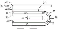
本申请实施例还提供了一种显示模组。图6为本申请一实施例提供的显示模组的结构示意图。如图6所示,显示模组包括上述任一实施例提供的显示面板10。显示面板10还包括位于弯折区S的远离显示区AA一侧的邦定区D。弯折区S呈弯折状态,邦定区D位于显示区AA的非显示侧。The embodiment of the present application also provides a display module. FIG. 6 is a schematic structural diagram of a display module provided by an embodiment of the present application. As shown in FIG. 6 , the display module includes the
如图6所示的显示模组还可以包括:至少一个功能膜片20,叠置在显示面板10的显示侧,并与防静电层18接触。至少一个功能膜片20可以包括偏光片221和盖板222,偏光片221和盖板222通过胶层223粘结。The display module shown in FIG. 6 may further include: at least one functional film 20 stacked on the display side of the
具体而言,以图4所示显示面板为例,显示面板还包括封装层12和防静电层18。封装层12叠置在边框区B的金属走线110的远离基板11的一侧,防静电层18叠置在阻隔层16的远离支撑层15的一侧,并覆盖边框区B的至少部分封装层12。这种情况下,结合图6所示显示模组可见,当至少一个功能膜片20叠置在封装层12的远离基板11一侧表面时,防静电层18可以插入封装层12和至少一个功能膜片20之间,从而可以将至少一个功能膜片20中的静电荷导出。Specifically, taking the display panel shown in FIG. 4 as an example, the display panel further includes an
如图6所示,显示模组还可以包括第一支撑层30、第二支撑层40、垫高块50。其中,第一支撑层30叠置在显示区AA的显示面板10的远离功能膜片20的一侧,第二支撑层40叠置在邦定区D的显示面板10的朝向第一支撑层30的一侧。垫高块50位于第一支撑层30和第二支撑层40之间,以补偿第一支撑层30和第二支撑层40之间的高度差。As shown in FIG. 6 , the display module may further include a
如图6所示的显示模组还可以包括绝缘胶带(图中未示出)。绝缘胶带覆盖防静电层18的至少部分区域。绝缘胶带包括露铜区,露铜区与防静电层18接触。后续通过将绝缘胶带中具有露铜区的铜层与终端机壳接触,便可以将防静电层18导出的静电荷释放到终端机壳,进而通过人体导入大地,实现静电释放的效果。The display module shown in FIG. 6 may further include an insulating tape (not shown in the figure). The insulating tape covers at least a partial area of the
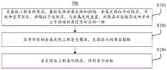
本申请实施例还提供了一种显示面板的制备方法。图7为本申请一实施例提供的显示面板的制备方法的流程示意图。如图7所示,制备方法700包括:The embodiment of the present application also provides a method for manufacturing a display panel. FIG. 7 is a schematic flowchart of a method for manufacturing a display panel provided by an embodiment of the present application. As shown in Figure 7, the
步骤S710,在基板上制备封装层,基板包括金属走线和挡墙,金属走线位于边框区,并延伸至弯折区,挡墙位于边框区,与金属走线叠置,封装层从边框区延伸并终止于挡墙的靠近弯折区的一侧。Step S710, preparing an encapsulation layer on the substrate. The substrate includes metal traces and retaining walls. The metal traces are located in the frame area and extend to the bending area. The retaining walls are located in the frame area and overlap the metal traces. The encapsulation layer extends from the frame The zone extends and terminates on the side of the retaining wall near the bend zone.
步骤S720,在弯折区的金属走线上制备支撑层,支撑层与封装层接触。In step S720, a support layer is prepared on the metal wiring in the bending area, and the support layer is in contact with the encapsulation layer.
例如采用喷墨打印方式制备支撑层。具体而言,先在弯折区的金属走线上喷涂支撑材料,待支撑材料流平后,对支撑材料进行固化,得到支撑层。固化方式可以是高温固化或光固化。For example, inkjet printing is used to prepare the supporting layer. Specifically, the support material is first sprayed on the metal traces in the bending area, and after the support material is leveled, the support material is cured to obtain a support layer. The curing method can be high temperature curing or light curing.
在一个实施例中,在步骤S720之前,还包括制备堤坝的步骤。具体而言,将支撑材料调整到第一粘稠度,采用喷墨打印方式在弯折区S远离边框区B的一侧喷涂支撑材料,对支撑材料进行固化,得到堤坝。这种情况下,步骤S720可执行为,将支撑材料调整到第二粘稠度,第二粘稠度小于第一粘稠度。采用喷墨打印方式在挡墙和堤坝之间喷涂支撑材料,待支撑材料流平后,对支撑材料进行固化,得到支撑层。In one embodiment, before step S720, a step of preparing a dam is further included. Specifically, the support material is adjusted to the first viscosity, and the support material is sprayed on the side of the bending area S away from the frame area B by inkjet printing, and the support material is cured to obtain a dam. In this case, step S720 may be performed as adjusting the support material to a second viscosity, and the second viscosity is smaller than the first viscosity. The support material is sprayed between the retaining wall and the embankment by inkjet printing, and after the support material is leveled, the support material is cured to obtain a support layer.
步骤S730,在支撑层上制备阻隔层,得到显示面板。Step S730, preparing a barrier layer on the support layer to obtain a display panel.
例如采用喷墨打印方式制备阻隔层。具体而言,先在支撑层上喷涂阻隔材料,待阻隔材料流平后,对阻隔材料进行固化,得到阻隔层。固化方式可以是高温固化或光固化。For example, the barrier layer is prepared by inkjet printing. Specifically, the barrier material is first sprayed on the support layer, and after the barrier material is leveled, the barrier material is cured to obtain the barrier layer. The curing method can be high temperature curing or light curing.
制备方法700还可以包括:在阻隔层上制备防静电层,防静电层在基板上的正投影覆盖边框区的至少部分封装层。The
例如,首先,采用蒸镀工艺在阻隔层上蒸镀金属层;然后,采用光刻、干刻工艺对金属层进行图形化,得到防静电层。For example, first, a metal layer is evaporated on the barrier layer by using an evaporation process; then, the metal layer is patterned by a photolithography and dry etching process to obtain an antistatic layer.
本申请实施例还提供了一种显示装置。图8为本申请一实施例提供的显示装置的结构示意图。如图8所示,显示装置包括本申请任一实施例提供的显示模组80。The embodiment of the present application also provides a display device. FIG. 8 is a schematic structural diagram of a display device provided by an embodiment of the present application. As shown in FIG. 8 , the display device includes a
显示装置可以是具有显示功能的智能终端,例如手机、电脑、电视、仪表等。The display device may be an intelligent terminal with a display function, such as a mobile phone, a computer, a television, an instrument, and the like.
为了例示和描述的目的已经给出了以上描述。此外,此描述不意图将本申请的实施例限制到在此公开的形式。尽管以上已经讨论了多个示例方面和实施例,但是本领域技术人员将认识到其某些变型、修改、改变、添加和子组合。The foregoing description has been presented for purposes of illustration and description. Furthermore, this description is not intended to limit the embodiments of the application to the forms disclosed herein. Although a number of example aspects and embodiments have been discussed above, those skilled in the art will recognize certain variations, modifications, changes, additions and sub-combinations thereof.
Claims (10)
Priority Applications (1)
| Application Number | Priority Date | Filing Date | Title |
|---|---|---|---|
| CN202310322998.6ACN116234351A (en) | 2023-03-29 | 2023-03-29 | Display panel, manufacturing method thereof, display module and display device |
Applications Claiming Priority (1)
| Application Number | Priority Date | Filing Date | Title |
|---|---|---|---|
| CN202310322998.6ACN116234351A (en) | 2023-03-29 | 2023-03-29 | Display panel, manufacturing method thereof, display module and display device |
Publications (1)
| Publication Number | Publication Date |
|---|---|
| CN116234351Atrue CN116234351A (en) | 2023-06-06 |
Family
ID=86577078
Family Applications (1)
| Application Number | Title | Priority Date | Filing Date |
|---|---|---|---|
| CN202310322998.6APendingCN116234351A (en) | 2023-03-29 | 2023-03-29 | Display panel, manufacturing method thereof, display module and display device |
Country Status (1)
| Country | Link |
|---|---|
| CN (1) | CN116234351A (en) |
Cited By (2)
| Publication number | Priority date | Publication date | Assignee | Title |
|---|---|---|---|---|
| CN117912367A (en)* | 2024-01-05 | 2024-04-19 | 昆山国显光电有限公司 | Support mechanism and display module |
| WO2025001052A1 (en)* | 2023-06-30 | 2025-01-02 | 华为技术有限公司 | Display module and electronic device |
- 2023
- 2023-03-29CNCN202310322998.6Apatent/CN116234351A/enactivePending
Cited By (2)
| Publication number | Priority date | Publication date | Assignee | Title |
|---|---|---|---|---|
| WO2025001052A1 (en)* | 2023-06-30 | 2025-01-02 | 华为技术有限公司 | Display module and electronic device |
| CN117912367A (en)* | 2024-01-05 | 2024-04-19 | 昆山国显光电有限公司 | Support mechanism and display module |
Similar Documents
| Publication | Publication Date | Title |
|---|---|---|
| CN112397559B (en) | Stretchable display module and preparation method thereof | |
| CN116234351A (en) | Display panel, manufacturing method thereof, display module and display device | |
| US10823996B2 (en) | Display panel and method of manufacturing the same, display device | |
| CN110262701B (en) | Display panel and display device | |
| CN112750883A (en) | Display panel and display device | |
| CN109887416B (en) | Flexible display substrate, manufacturing method thereof and display device | |
| CN114388679B (en) | display device | |
| TW202206904A (en) | Display apparatus | |
| US12016195B2 (en) | Display device including corner display having cutouts and dams | |
| EP4586790A2 (en) | Display device and method of providing the same | |
| CN110377184A (en) | A kind of display panel and display device | |
| CN111210730A (en) | Display panel and display device | |
| WO2021017478A1 (en) | Display panel and display device | |
| CN115428160B (en) | Display substrate, manufacturing method thereof and display device | |
| US12429738B2 (en) | Display panel | |
| CN115275056A (en) | Flexible display panel, preparation method thereof and display device | |
| CN118155505A (en) | Display module and manufacturing method thereof, polarizer assembly, and display device | |
| CN110764302A (en) | A display panel and its preparation method and alignment system | |
| US12107202B2 (en) | Electronic device and manufacturing method thereof | |
| US20250048914A1 (en) | Foldable display module and foldable display device | |
| CN111650771B (en) | Array substrate, manufacturing method thereof and display device | |
| CN116847676A (en) | Display panel and display device | |
| CN115411088A (en) | Display panel and display device | |
| US20250107364A1 (en) | Display device and method of fabricating the same | |
| US20250268064A1 (en) | Display panel and method for manufacturing display panel, and display module |
Legal Events
| Date | Code | Title | Description |
|---|---|---|---|
| PB01 | Publication | ||
| PB01 | Publication | ||
| SE01 | Entry into force of request for substantive examination | ||
| SE01 | Entry into force of request for substantive examination |