CN1162249A - Eye movement perception method and system - Google Patents
Eye movement perception method and systemDownload PDFInfo
- Publication number
- CN1162249A CN1162249ACN 95193447CN95193447ACN1162249ACN 1162249 ACN1162249 ACN 1162249ACN 95193447CN95193447CN 95193447CN 95193447 ACN95193447 ACN 95193447ACN 1162249 ACN1162249 ACN 1162249A
- Authority
- CN
- China
- Prior art keywords
- energy
- light
- border
- eye
- hot spots
- Prior art date
- Legal status (The legal status is an assumption and is not a legal conclusion. Google has not performed a legal analysis and makes no representation as to the accuracy of the status listed.)
- Pending
Links
Images


Landscapes
- Measurement Of The Respiration, Hearing Ability, Form, And Blood Characteristics Of Living Organisms (AREA)
Abstract
Description
Translated fromChinese发明领域field of invention
本发明主要涉及到眼科激光手术,更具体地,涉及到用于眼科判别、诊断和手术过程的眼动感知方法和系统。The present invention mainly relates to ophthalmic laser surgery, and more specifically, relates to an eye movement sensing method and system for ophthalmic discrimination, diagnosis and surgical procedures.
发明背景Background of the invention
眼科判别、诊断以及/或手术过程涉及到各种设备,例如倍频红外激光器、固体激光器、射频能源以及超声系统,只例举了一些。在每一个这样的系统/过程中,感知和/或控制眼睛的位置和运动是十分关键的。Ophthalmic diagnostic, diagnostic, and/or surgical procedures involve a variety of equipment such as frequency-doubled infrared lasers, solid-state lasers, radio frequency energy sources, and ultrasound systems, just to name a few. Perceiving and/or controlling eye position and movement is critical in each of these systems/processes.
例如,光折射角膜切除(photorefractive keratectomy,PRK)是一种用于通过调整角膜曲率,实现激光校正眼睛聚焦不足的方法。PRK区别于传统眼科手术中以激光器为基础的器件使用,例如,组织切除和热力联接。PRK通常使用193纳米波长的准分子激光束,在光分解的处理中切除掉一些角膜组织。这方面大多数的临床工作,用光通量约120-195mJ/cm2及大约5-10Hz的脉冲重复率的激光器完成。这个过程被称作“角膜塑造(corneal culpting)。For example, photorefractive keratectomy (PRK) is a procedure used to achieve laser correction of ocular infocus by adjusting the curvature of the cornea. PRK differs from the use of laser-based devices in traditional ophthalmic surgery, eg, tissue ablation and thermal coupling. PRK typically uses an excimer laser beam at a wavelength of 193 nanometers to ablate some corneal tissue in a photolysis process. Most clinical work in this area is done with lasers with a fluence of about 120-195 mJ/cm2 and a pulse repetition rate of about 5-10 Hz. This process is called "corneal culpting".
在角膜塑造之前,上皮或角膜的外层被机械地移开以露出基质前表面的鲍曼氏膜。这时,在鲍曼氏膜上的激光切除可以开始了,在这一过程中优选使用准分子激光束。在根据重塑前面基质的需要,按不同深度切除角膜组织的切除过程中,光束采用不同的遮蔽。之后,上皮很快重新生长,并在重塑区域重新形成表面,以产生光学上正确(或大至接近这样)的角膜。在一些情况下,角膜的表面片被折叠在一边,并将暴露的角膜基质表面切割成理想的表面形状,角膜片然后复位。Prior to corneal shaping, the epithelium, or outer layer of the cornea, is mechanically removed to expose the Bowman's membrane on the anterior surface of the stroma. At this point, laser ablation of the Bowman's membrane can begin, preferably using an excimer laser beam in this process. The beam is shaded differently during the ablation procedure in which corneal tissue is removed at different depths according to the need to reshape the anterior stroma. Afterwards, the epithelium quickly regrows and resurfaces in the remodeled areas to produce an optically correct (or as large as this) cornea. In some cases, the surface sheet of the cornea is folded over and the exposed corneal stroma surface is cut to the desired surface shape, and the corneal sheet is then repositioned.
光学疗法角膜切除(PTK)是一个包括和PRK所需设备功能相同的设备的过程。除了重塑角膜,PTK过程和PRK的区别在于,PTK使用准分子激光束治疗由疾病引起的表面角膜营养不良,这种情况一般要求角膜移植。Phototherapeutic keratectomy (PTK) is a procedure that includes functionally equivalent equipment to that required for PRK. Aside from reshaping the cornea, the PTK procedure differs from PRK in that PTK uses an excimer laser beam to treat superficial corneal dystrophies caused by disease, a condition that typically requires corneal transplantation.
在这两个过程中,由于眼睛位置误差:包括在眼睛和手术激光器之间原始对中误差以及/或由无意(快速)眼动,头部运动或手术设备运动引起的随之而来的运动引起的手术误差,可能降低手术的屈光效果。运动或位置的误差是很重要的,因为治疗激光器的效率依赖于它会集在病的理论视轴上,视轴实际上大约是病人瞳孔的中心。然而,部分由于有后效的眼动及被称作快速眼动的无意眼动,这个视轴是很难确定的。快速眼动是人类视觉固有的高速运动(即持续时间很短,10~20毫秒,并且通常眼球转动最多1°),并且用来向视网膜提供动态影像。快速眼动尽管振幅很小,但由于心理影响、身体化学、手术灯光条件等因素,病人和病人之间有很大差别。During both procedures, due to eye position errors: including errors in the original alignment between the eye and the surgical laser and/or consequent movements caused by inadvertent (rapid) eye movements, head movements or surgical equipment movements The surgical error caused may reduce the refractive effect of the operation. Errors in motion or position are important because the efficiency of the therapeutic laser depends on it being centered on the patient's theoretical visual axis, which is actually approximately the center of the patient's pupil. However, this visual axis is difficult to determine due in part to eye movements with aftereffects and involuntary eye movements known as rapid eye movements. Rapid eye movements are high-speed movements (ie, very short in duration, 10-20 milliseconds, and usually a maximum of 1° of eye rotation) that are inherent in human vision and are used to provide moving images to the retina. REM, although small in amplitude, can vary widely from patient to patient due to psychological influences, body chemistry, operating light conditions, and other factors.
解决眼位置误差的一个方法是通过使用抓握装置或吸环在手术中物理上固定病人的眼睛以尽量减小它。然而,吸环的侵入会扭曲眼睛的形状,这样会影响手术的精确性。另外,由于吸环通常由外科医生抓握,外科医生低频但是大幅度的手部运动,会成为影响手术精确性的因素。One approach to address eye position error is to minimize it by physically immobilizing the patient's eye during surgery using a grasping device or suction ring. However, the intrusion of the suction ring distorts the shape of the eye, which affects the precision of the surgery. In addition, because the suction ring is usually grasped by the surgeon, the low-frequency but large-scale hand movement of the surgeon will become a factor affecting the accuracy of the operation.
解决眼位置误差的另一个方法是用非侵入的方法感知眼睛的位置。在现有技术中已知的一种感知技术/系统是第一和第四Purkinje反射跟踪器。第一和第四Purkinje反射指的是基于第一Purkinje像和第四Purkinje像的图象,第一Purkinje是角膜前表面反射成像,第四Purkinje像是眼睛晶状体后的反射像的成像。这种技术/系统可以用来跟踪眼睛的x-y位置。然而,对于特定的角膜塑造手术过程,第一Purkinje表面被切除了,这样,这种技术/系统对于角膜塑造手术是无效的。Another approach to address eye position error is to sense eye position in a non-invasive way. One perception technique/system known in the prior art is the first and fourth Purkinje reflection trackers. The first and fourth Purkinje reflections refer to images based on the first Purkinje image and the fourth Purkinje image, the first Purkinje is the reflection image of the front surface of the cornea, and the fourth Purkinje image is the imaging of the reflection image behind the lens of the eye. This technique/system can be used to track the x-y position of the eye. However, for certain orthokeratology procedures, the first Purkinje surface is excised, thus, this technique/system is not effective for orthokeratology procedures.
发明概述Summary of the invention
因此,本发明的一个目的是提供一种用于感知眼睛位置和运动的方法及系统。It is therefore an object of the present invention to provide a method and system for sensing eye position and movement.
本发明的另一个目的是提供一种非侵入方式的感知眼睛位置和运动的方法和系统。Another object of the present invention is to provide a method and system for sensing eye position and movement in a non-invasive manner.
另外,本发明的另一个目的的是提供一种感知眼睛快速运动的方法和系统。In addition, another object of the present invention is to provide a method and system for sensing rapid eye movement.
本发明进一步的目的是提供一种感知眼睛位置和运动的方法和系统作为包括角膜塑造过程的眼科手术的工具。It is a further object of the present invention to provide a method and system for sensing eye position and movement as a tool in ophthalmic surgery including corneal shaping procedures.
本发明的另一个目的是提供一种感知眼睛位置和运动的方法和系统,使得在手术中眼睛是安全的。Another object of the present invention is to provide a method and system for sensing the position and movement of the eye so that the eye is safe during surgery.
在说明书和附图之后,本发明其他目的和优点会变得更加明显。Other objects and advantages of the invention will become more apparent after the description and drawings.
按照本发明,提供了一种方法和系统来感知眼睛的运动。光源产生在近红外900纳米波长范围内的调制光束。光学传送装置将每个激光调制脉冲转化成多个光斑。光斑被聚焦,这样它们刚好处于一个边界上相应的多个位置上,边界的运动和眼睛运动一致。边界可以由两个不同折射率的可见相邻平面确定。边界可以是自然产生的边界(例如,虹膜/瞳孔边界或虹膜/巩膜边界)或是一个人工边界(例如,画的、印在或放在眼睛上的墨水环,或一个固定在眼睛上的反射率增强片)。能量被接收光斑的边界上的每个位置反射。光学接收装置探测从每个位置反射的能量。一个或多个位置反射能量的变化可说明眼睛的运动。According to the present invention, a method and system are provided for sensing eye movement. The light source produces a modulated beam in the near-infrared 900nm wavelength range. An optical delivery device converts each laser modulation pulse into multiple spots. The spots are focused so that they are at exactly the corresponding positions on a boundary whose movement coincides with the eye movement. A boundary can be defined by two visible adjacent planes of different refractive indices. The boundary can be a naturally occurring boundary (e.g., an iris/pupil boundary or an iris/sclera boundary) or an artificial boundary (e.g., an ink ring drawn, imprinted, or placed on the eye, or a reflection fixed to the eye rate enhancer). Energy is reflected by each location on the boundary of the received spot. An optical receiver detects the energy reflected from each location. Changes in reflected energy at one or more locations may indicate eye movement.
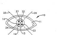
图1A是根据本发明的眼睛的平面图,有四个光斑位于眼睛虹膜/瞳孔边界上;Figure 1A is a plan view of an eye according to the present invention with four spots of light located on the iris/pupil boundary of the eye;
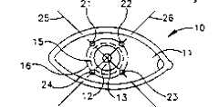
图1B是眼睛的平面图,四个光斑在眼睛虹膜/巩膜的边界上;Figure 1B is a plan view of the eye, with four spots on the iris/sclera boundary of the eye;
图1C是眼睛的平面图,墨水圈固定在眼睛的虹膜/巩膜边界上,同时四个光斑放置在墨水圈/巩膜边界上;Figure 1C is a plan view of the eye, the ink circle is fixed on the iris/sclera boundary of the eye, and four light spots are placed on the ink circle/sclera boundary;
图1D是眼睛的平面图,双墨水圈固定在眼睛的巩膜上,同时四个光斑位于双墨水圈的内墨水圈和外墨水圈之间的边界上;Figure 1D is a plan view of the eye, the double ink circle is fixed on the sclera of the eye, and the four light spots are located on the boundary between the inner ink circle and the outer ink circle of the double ink circle;
图1E是眼睛的平面图,有一个反射增强片固定在上面,并且有四个光斑放在眼睛和该片之间的边界上;Figure 1E is a plan view of the eye with a reflective enhancement sheet affixed thereto and four light spots placed on the boundary between the eye and the sheet;
图2是依据本发明的优选实施方案的眼动感知系统的框图;2 is a block diagram of an eye movement sensing system according to a preferred embodiment of the present invention;
图3是图2中光纤束装置的截面图;Fig. 3 is a sectional view of the optical fiber bundle device in Fig. 2;
图4是用于本发明的传送部分聚焦光路的优选实施方案光学装置的框图;Figure 4 is a block diagram of a preferred embodiment optical arrangement for the delivery of the partial focusing optical path of the present invention;
图5是图2中所示典型多路峰值电路的方框图。FIG. 5 is a block diagram of a typical multi-channel peaking circuit shown in FIG. 2 .
发明详述Detailed description of the invention
现在参照附图,特别是图1A-1E,给出了人眼的平面图,并通常用数字10表示。这个平面视图中,眼睛10包括了3个可见相邻平面,称为巩膜或“眼白”11,虹膜12以及瞳孔13。每个巩膜11,虹膜12,以及瞳孔13有各自的反射率。Referring now to the drawings, and in particular FIGS. 1A-1E , there are shown plan views of the human eye, generally indicated by the
本发明的方法基于优选使用4个光斑,由圆圈21、22、23、24表示。如图示,光斑21和23位于轴25上,而光斑22和24位于轴26上。轴25和轴26彼此垂直。光斑21、22、23和24被聚焦并放置在如图1A所示的虹膜/瞳孔的边界14上,或如图1B所示的虹膜/巩膜边界15上。另外,人工边界也可以使用。例如,如图1C所示,墨水环16也可以放置在虹膜/巩膜边界15处,产生一个墨水环/巩膜边界17,可以替代或增强边缘15和巩膜11之间的反射率差。一种通常在眼科手术中做标记的墨水是龙胆紫墨水,例如,商品名为“Visitec”的墨水。如图1D所示,双墨水圈18可被放在巩膜11上,包括有第一反射率的内墨水环18a以及具有第二反射率的外墨水环18b。光斑21、22、23和24放置在墨水环18a和18b之间的边界18c上的垂直轴25、26上。另一种方法在图1E中说明,其中圆形反射增强片19固定在眼睛10的某个部分上(例如,巩膜11)并且光斑21、22、23和24放在通过增强片19的中心的相互垂直的轴25、26上。The method of the invention is based on preferably using 4 spots, represented by
在每种情况下,工作原理是相同的。四个光斑、21、22、23和24能量相等,并且基本平均地放在感兴趣的圆形边界上。这种布置可以感知以下面方式的两轴运动。在相应的边界上,每个光斑21、22、23和24在其位置上引起特定量的反射。由于相应边界的运动和眼睛运动一致,光斑21、22、23和24的反射的量随着眼睛运动发生变化。将四个光斑均匀地放置在圆形几何边界上,通过相邻光斑反射量的变化,水平或垂直方向眼睛的运动被探测。例如,眼睛的水平运动可以通过比较光斑21、24的反射量的和与光斑22、23的反射量的和监视。类似地眼睛的垂直运动可以通过比较光斑21和22的反射量的和与光斑23、24的反射量的和监视。In each case, the working principle is the same. The four spots, 21, 22, 23 and 24, are of equal energy and placed substantially evenly on the circular boundary of interest. This arrangement can sense two-axis motion in the following manner. Each
对于图1A-1E中所示的所有情况,以上描述的方法是完全相同的,以下的说明将集中在使用虹膜/瞳孔边界14的图1A的实施方案上。使用虹膜/瞳孔边界14是优选的,因为它是自然发生的,并且它代表了最大的反射特性对比。其主要的原因在于瞳孔13沿入射路径直接反射光线而虹膜12反射的光线是发散的。注意到巩膜11和墨水圈16也发散地反射光线,同时巩膜11比虹膜12或墨水圈16的反射更发散。因此,巩膜11和虹膜12结合使用(即虹膜/巩膜边界15)并且墨水圈16可以用来代替或增强虹膜/巩膜边界15。The methods described above are identical for all cases shown in FIGS. 1A-1E , and the following description will focus on the embodiment of FIG. 1A using the iris/
基于本发明是用于眼科手术过程中的事实,光斑21、22、23和24的波长和能量必须加以考虑。光斑最好在可见光谱范围之外,这样不会干扰或阻碍医生对进行手术的眼睛的观察。另外,光斑必须是“对眼安全的”以符合美国国家标准协会(ANSI)安全标准。有许多光波长满足以上的要求,例如,光斑21、22、23和24在近红外900纳米波长范围内。在这个范围内的光线符合所述的标准,并且是可以用方便可用的、经济上可以负担的光源提供。一种这样的光源是工作在4KHz频率下、高脉冲重复率、905纳米GaAs激光器,它在50纳秒脉冲期内产生10纳焦耳能量,这按ANSI定义是对眼睛安全的脉冲。Due to the fact that the present invention is used during ophthalmic surgery, the wavelength and energy of the
光斑21、22、23、24的大小根据感兴趣的边界而不同。例如,用在虹膜/瞳孔边界14上的光斑大小为1毫米,而用于虹膜/巩膜边界15上的光斑大小为2毫米。然而,应理解光斑的大小不是固定的,并可以实际根据病人和照明背景的不同而变化。The size of the light spots 21, 22, 23, 24 varies according to the boundary of interest. For example, the spot size used on the iris/
用于实现本发明的方法的一个优选实施方案系统,通常用数字100表示,将借助于图2中的框图进行说明。系统100可以被分为传送部分和接收部分。实际上,如上所述,传送部分将光斑21、22、23和24投射到眼睛10上,而接收部分监视光斑21、22、23和24引起的反射。A preferred embodiment system for carrying out the method of the present invention, generally indicated by the numeral 100, will be illustrated with the aid of the block diagram in FIG. 2 . System 100 can be divided into a transmitting part and a receiving part. In fact, as mentioned above, the transmitting part projects the light spots 21 , 22 , 23 and 24 onto the
传送部分包括一个905纳米脉冲激光二极管102,将光通过光纤104传送到光纤组件105上,它将从激光器102送来的每个脉冲分束并延迟形成优选的四个等能量脉冲。组件105包括一到四光学分束器106将四个能量相等的脉冲送入光纤108、110、112、114。这些光学分束器是可以买到的(例如Cansta出品的HLS2×4型和E-Tek Dynamics出品的MMSC-0404-0850-A-H-1型)。为了用单个处理器处理光纤108、110、112和114传输的每个脉冲引起的反射,每个脉冲用相应的光纤延迟线(或光学调制器)109、111、113和115进行专门的调制。例如,延迟线109引起的延迟为0,即DELAY=0X,其中X是延迟增量,延迟线111引起的延迟为X,即DELAY=1X,等。The delivery section consists of a 905nm pulsed laser diode 102 which transmits light through an optical fiber 104 to a fiber optic assembly 105 which splits and delays each pulse from the laser 102 into preferably four pulses of equal energy. Assembly 105 includes one to four optical beam splitters 106 to send four pulses of equal energy into optical fibers 108 , 110 , 112 , 114 . These optical beam splitters are commercially available (eg, models HLS2x4 from Cansta and MMSC-0404-0850-A-H-1 from E-Tek Dynamics). Each pulse is specifically modulated with a corresponding fiber delay line (or optical modulator) 109, 111, 113, and 115 in order to handle the reflections caused by each pulse transmitted by fibers 108, 110, 112, and 114 with a single processor. For example, the delay caused by the delay line 109 is 0, ie DELAY=0X, where X is the delay increment, the delay caused by the delay line 111 is X, ie DELAY=1X, and so on.
脉冲重复频率和延迟增量X是可选择的,这样,系统100的数据率比所感兴趣的运动的速度快。涉及到快速眼动,系统100的数据率至少要几百赫兹。例如,通过1)选择小但是足够的X的值,使处理器160可以操作数据(例如,160纳秒),以及2)选择激光器102脉冲间的时间为250微秒(即激光器102的脉冲率为4KHz),可以实现4KHz的系统数据率。The pulse repetition frequency and delay increment X are selectable so that the data rate of the system 100 is faster than the speed of motion of interest. With respect to rapid eye movement, the data rate of the system 100 is at least a few hundred hertz. For example, by 1) choosing a small but sufficient value of X so that the
四个等能量脉冲通过形成光纤束123的光纤116、118、120和122离开组件105,光纤束123中光纤116、118、120,122的中心的连线形成一个方形(虚线),每个光纤的中心占一个角,如图3中的截面图所示。为了清楚起见,许多光纤束123的公知的结构特性(例如,光纤的包层,垫层,隔离器等)被省略了。Four pulses of equal energy leave the assembly 105 through the
从组件105来的光线通过一个光学偏振器124,除去光线中垂直的部分,输出箭头126表明的水平偏振光线。水平偏振光束126进入聚焦光路130,在这里光束126的间隙根据感兴趣的边界进行调整。另外,可提供变焦能力以调整由光斑21、22、23和24组成图形的大小。这种能力使系统100可以适应不同的病人,边界等。Light from module 105 passes through an optical polarizer 124 which removes the vertical portion of the light and outputs horizontally polarized light as indicated by arrow 126 . Horizontally polarized beam 126 enters focusing optical path 130 where the gap of beam 126 is adjusted according to the boundary of interest. Additionally, a zoom capability may be provided to adjust the size of the pattern made up of
许多光学排列可以作为聚焦光路130,图4中的例子说明了一种这样的装置。在图4中,光纤束123放在显微镜物镜1302的工作距离上。显微镜物镜1302的数值孔径应选为和光纤116,118,120和122的数值孔径相等。显微镜物镜1302放大并准直入射的光线。变焦透镜1304为进一步的调整提供附加的放大因子。准直透镜1306的焦距等于它到变焦透镜1304的像的距离,这样它的输出被准直了。成象透镜1308的焦距是到眼睛的距离,这样,成象透镜1308使光线在眼睛的角膜表面聚焦成四个清晰的光斑。A number of optical arrangements can serve as the focusing optical path 130, and the example in FIG. 4 illustrates one such arrangement. In FIG. 4 ,
再次参照图2,偏振光束分束器140接收从聚焦光路130来的水平偏振光束126。在现有技术中,偏振分束器是公知的。例如,分束器140是Newport-klinger制造的10FC16PB.5型。分束器140设计成只传送水平偏振光,并且反射垂直偏振光。因此,分束器140只传送箭头142标明的水平偏振光束126。这样,只有水平偏振光进入眼睛10形成光斑21、22、23和24。眼睛10反射后,光线能量被解偏(即,它包括水平和垂直偏振成分),如交叉的箭头150所示。反射光线中的垂直部分如箭头152所示传输/反射。这样,分束器140可从反射光能量中分离传输光线能量,以进行精确测量。Referring again to FIG. 2 , polarizing beam splitter 140 receives horizontally polarized beam 126 from focusing optical path 130 . Polarizing beam splitters are well known in the prior art. For example, beam splitter 140 is model 10FC16PB.5 manufactured by Newport-Klinger. Beam splitter 140 is designed to transmit only horizontally polarized light and reflect vertically polarized light. Thus, beam splitter 140 transmits only horizontally polarized beam 126 indicated by arrow 142 . In this way, only horizontally polarized light enters the
光斑21、22、23和24反射光线的垂直偏振部分,通过聚焦透镜154成像在红外探测器156上。探测器156将它的信号送入多路复用峰值探测电路158,它实际上是一个峰值采样和保持电路,在现有技术中有许多种。电路158设计为根据激光器102的脉冲重复频率和延迟X对探测器156采样(并保持峰值)。例如,如果激光器102的脉冲重复频率为4KHz,电路158每250毫秒收集光斑21、22、23和24的反射。The light spots 21 , 22 , 23 and 24 reflect the vertically polarized part of the light, which is imaged on the
例如,红外探测器156是EG&G出品的C30916E型雪崩光电二极管。一个典型的时分多路复用峰值电路158在图5中的框图中进行了更详细的说明。探测器156的探测输出信号输入到四个峰值保持电路1581、1582、1583和1584。对于给定的传输激光脉冲,探测器输出通过相应光延迟线109、111、113、115的延迟,包括四个时间上分开的脉冲。这四个时间分开的脉冲被馈送到峰值保持电路1581、1582、1583和1584。和激光器启动命令同步,输入使能信号也被馈送到峰值和保持电路。每个峰值保持电路的使能信号经过延迟电路1585、1586、1587和1588延迟,该延迟与延迟线109、111、113和115的延迟对应,使四个脉冲的每一个都输入到峰值保持电路。例如,延迟电路1585产生相应于延迟线109的零时间延迟,延迟电路1586产生相应于延迟线111的时间延迟X,等等。这样,相应于一组四个光斑的反射能量被收集,同时探测信号均被四个峰值保持电路1581、1582、1583和1583得到。这时,输出多路复用器1589读出每个峰值保持电路保持的值,并顺序地输入到处理器160。
送到处理器160上的与每组四个光斑反射能量对应的值(即激光器102的每个脉冲)可以用于确定眼睛运动的水平和垂直分量,例如,用R21、R22、R23、R24分别代表一组光斑21、22、23和24反射光的被探测量。水平运动的量可以直接从归一化关系(1)确定,
注意归一化(即,被R21+R22+R23+R24除)减少了信号强度变化的影响。Note that normalization (ie, division by R21+R22+R23+R24) reduces the effect of signal strength variations.
一旦经过处理,表明眼睛运动(或缺少运动)的反射量差可以用于很多方面。例如,过量的眼睛运动量可以用来触发报警器170。另外,反射量差可以作为跟踪伺服系统172的反馈控制,用于切除激光器的定位。更进一步,反射量差可以显示在显示器174上用于监视或教学的目的。Once processed, the difference in the amount of reflection that indicates eye movement (or lack thereof) can be used in many ways. For example, an excessive amount of eye movement may be used to trigger the alarm 170 . In addition, the reflectance difference can be used as a feedback control for the tracking servo system 172 for the positioning of the ablation laser. Still further, the reflectance difference can be displayed on the display 174 for monitoring or teaching purposes.
本发明的优点是很多的,眼动可以用非侵入的方法和装置感知。本发明在不同的眼科手术过程中有很多用途,且对眼睛没有破坏性的影响或干扰医生的视线。另外,感知快速眼动所需的数据率可以很容易并且很经济地得到。The advantages of the present invention are numerous, eye movements can be sensed with non-invasive methods and devices. The present invention has many uses in different ophthalmic procedures without damaging the eyes or interfering with the doctor's vision. In addition, the data rates required to sense REM are readily and economically available.
虽然,本发明用一个具体的实施方案说明,有很多变化和调整在所述指导下对本领域技术人员而言,是显而易见的。可以理解的是,在随后的权利要求范围内,本发明可以用不同于具体描述的方法实施。Although, the invention has been illustrated in terms of a specific embodiment, many variations and modifications will be apparent to those skilled in the art in light of the described teachings. It is to be understood that, within the scope of the appended claims, the invention may be practiced otherwise than as specifically described.
新的、期望受美国专利保护的权利要求是:The new claims expected to be protected by the U.S. patent are:
Claims (40)
Priority Applications (1)
| Application Number | Priority Date | Filing Date | Title |
|---|---|---|---|
| CN 95193447CN1162249A (en) | 1994-04-25 | 1995-04-18 | Eye movement perception method and system |
Applications Claiming Priority (2)
| Application Number | Priority Date | Filing Date | Title |
|---|---|---|---|
| US08/232,990 | 1994-04-25 | ||
| CN 95193447CN1162249A (en) | 1994-04-25 | 1995-04-18 | Eye movement perception method and system |
Publications (1)
| Publication Number | Publication Date |
|---|---|
| CN1162249Atrue CN1162249A (en) | 1997-10-15 |
Family
ID=5082564
Family Applications (1)
| Application Number | Title | Priority Date | Filing Date |
|---|---|---|---|
| CN 95193447PendingCN1162249A (en) | 1994-04-25 | 1995-04-18 | Eye movement perception method and system |
Country Status (1)
| Country | Link |
|---|---|
| CN (1) | CN1162249A (en) |
Cited By (4)
| Publication number | Priority date | Publication date | Assignee | Title |
|---|---|---|---|---|
| CN101873823B (en)* | 2007-11-29 | 2012-06-27 | 浜松光子学株式会社 | Eyeball motion measurement apparatus |
| CN103446676A (en)* | 2006-10-16 | 2013-12-18 | Oraya治疗公司 | Ocular radiosurgery |
| CN104216122A (en)* | 2013-05-31 | 2014-12-17 | 原相科技股份有限公司 | Eyeball tracking device and optical assembly thereof |
| US9272161B2 (en) | 2006-12-13 | 2016-03-01 | Oraya Therapeutics, Inc. | Orthovoltage radiotherapy |
- 1995
- 1995-04-18CNCN 95193447patent/CN1162249A/enactivePending
Cited By (5)
| Publication number | Priority date | Publication date | Assignee | Title |
|---|---|---|---|---|
| CN103446676A (en)* | 2006-10-16 | 2013-12-18 | Oraya治疗公司 | Ocular radiosurgery |
| US9272161B2 (en) | 2006-12-13 | 2016-03-01 | Oraya Therapeutics, Inc. | Orthovoltage radiotherapy |
| CN101873823B (en)* | 2007-11-29 | 2012-06-27 | 浜松光子学株式会社 | Eyeball motion measurement apparatus |
| CN104216122A (en)* | 2013-05-31 | 2014-12-17 | 原相科技股份有限公司 | Eyeball tracking device and optical assembly thereof |
| CN104216122B (en)* | 2013-05-31 | 2016-09-28 | 原相科技股份有限公司 | Eyeball tracking device and optical assembly thereof |
Similar Documents
| Publication | Publication Date | Title |
|---|---|---|
| JP3499874B2 (en) | Eye movement detection system | |
| US6302879B1 (en) | Laser beam delivery and eye tracking system | |
| US5782822A (en) | Method and apparatus for removing corneal tissue with infrared laser radiation | |
| KR101107482B1 (en) | Method and apparatus for eye alignment | |
| US20020013577A1 (en) | Laser beam delivery and eye tracking system | |
| MXPA01010535A (en) | Optimization of ablation correction of an optical system and associated methods. | |
| EP1369079A1 (en) | Zoom device for eye tracker control system and associated methods | |
| US20060158639A1 (en) | Eye tracker and pupil characteristic measurement system and associated methods | |
| CN1162249A (en) | Eye movement perception method and system | |
| CA2188038C (en) | Eye movement sensing method and system | |
| AU763206B2 (en) | Method and apparatus for removing corneal tissue with infrared laser radiation |
Legal Events
| Date | Code | Title | Description |
|---|---|---|---|
| C06 | Publication | ||
| PB01 | Publication | ||
| C10 | Entry into substantive examination | ||
| SE01 | Entry into force of request for substantive examination | ||
| C02 | Deemed withdrawal of patent application after publication (patent law 2001) | ||
| WD01 | Invention patent application deemed withdrawn after publication |