CN116209534A - Cutting insert, rotary tool and method for manufacturing cutting workpiece - Google Patents
Cutting insert, rotary tool and method for manufacturing cutting workpieceDownload PDFInfo
- Publication number
- CN116209534A CN116209534ACN202180055269.8ACN202180055269ACN116209534ACN 116209534 ACN116209534 ACN 116209534ACN 202180055269 ACN202180055269 ACN 202180055269ACN 116209534 ACN116209534 ACN 116209534A
- Authority
- CN
- China
- Prior art keywords
- cutting
- opening
- hole
- rotary cutter
- rotation axis
- Prior art date
- Legal status (The legal status is an assumption and is not a legal conclusion. Google has not performed a legal analysis and makes no representation as to the accuracy of the status listed.)
- Granted
Links
Images


Classifications
- B—PERFORMING OPERATIONS; TRANSPORTING
- B23—MACHINE TOOLS; METAL-WORKING NOT OTHERWISE PROVIDED FOR
- B23B—TURNING; BORING
- B23B27/00—Tools for turning or boring machines; Tools of a similar kind in general; Accessories therefor
- B23B27/14—Cutting tools of which the bits or tips or cutting inserts are of special material
- B23B27/16—Cutting tools of which the bits or tips or cutting inserts are of special material with exchangeable cutting bits or cutting inserts, e.g. able to be clamped
- B23B27/1603—Cutting tools of which the bits or tips or cutting inserts are of special material with exchangeable cutting bits or cutting inserts, e.g. able to be clamped with specially shaped plate-like exchangeable cutting inserts, e.g. chip-breaking groove
- B23B27/1611—Cutting tools of which the bits or tips or cutting inserts are of special material with exchangeable cutting bits or cutting inserts, e.g. able to be clamped with specially shaped plate-like exchangeable cutting inserts, e.g. chip-breaking groove characterised by having a special shape
- B—PERFORMING OPERATIONS; TRANSPORTING
- B23—MACHINE TOOLS; METAL-WORKING NOT OTHERWISE PROVIDED FOR
- B23B—TURNING; BORING
- B23B51/00—Tools for drilling machines
- B23B51/0002—Drills with connected cutting heads, e.g. with non-exchangeable cutting heads; Drills with a single insert extending across the rotational axis and having at least two radially extending cutting edges in the working position
- B23B51/0003—Drills with connected cutting heads, e.g. with non-exchangeable cutting heads; Drills with a single insert extending across the rotational axis and having at least two radially extending cutting edges in the working position with exchangeable heads or inserts
- B23B51/0005—Drills with connected cutting heads, e.g. with non-exchangeable cutting heads; Drills with a single insert extending across the rotational axis and having at least two radially extending cutting edges in the working position with exchangeable heads or inserts with cutting heads or inserts attached by wedge means
- B—PERFORMING OPERATIONS; TRANSPORTING
- B23—MACHINE TOOLS; METAL-WORKING NOT OTHERWISE PROVIDED FOR
- B23B—TURNING; BORING
- B23B51/00—Tools for drilling machines
- B23B51/06—Drills with lubricating or cooling equipment
- B23B51/068—Details of the lubricating or cooling channel
Landscapes
- Engineering & Computer Science (AREA)
- Mechanical Engineering (AREA)
- Drilling Tools (AREA)
- Milling Processes (AREA)
- Cutting Tools, Boring Holders, And Turrets (AREA)
- Milling, Broaching, Filing, Reaming, And Others (AREA)
Abstract
Description
Translated fromChinese技术领域technical field
本公开涉及在被切削件的切削加工中使用的切削刀片、旋转刀具以及切削加工物的制造方法。The present disclosure relates to a cutting insert used for cutting a workpiece, a rotary cutter, and a method of manufacturing a cut object.
背景技术Background technique
以往,已知有使金属等被切削件进行旋转并进行切削的钻头等旋转刀具。用于旋转刀具的切削刀片具有在前端面开口的贯通孔(例如,参照专利文献1、2)。冷却液能够在贯通孔中流动。Conventionally, a rotary cutting tool such as a drill that rotates and cuts a workpiece such as metal is known. A cutting insert used for a rotary cutter has a through-hole opened at a front end surface (for example, refer to
在先技术文献prior art literature
专利文献patent documents
专利文献1:日本特表2011-504810号公报Patent Document 1: Japanese National Publication No. 2011-504810
专利文献2:日本特开2014-172167号公报Patent Document 2: Japanese Patent Laid-Open No. 2014-172167
发明内容Contents of the invention
本公开的一方案中的切削刀片沿着旋转轴从第一端朝向第二端延伸,所述切削刀片具有:切削部,其位于所述第一端侧;以及轴部,其位于所述第二端侧,且沿着所述旋转轴延伸。所述切削部具有:切削刃,其位于所述第一端侧;端面,其位于所述第二端侧;以及第一贯通孔,其从所述端面朝向所述第一端延伸。所述轴部从所述端面朝向所述第二端延伸。所述第一贯通孔具有:第一开口,其位于所述第一端侧;以及第二开口,其位于所述第二端侧。所述第一开口位于比所述第二开口靠所述旋转轴的旋转方向的后方的位置。A cutting insert in one aspect of the present disclosure extends from a first end toward a second end along a rotation axis, the cutting insert has: a cutting portion located on the first end side; and a shaft portion located on the second end side. The two end sides extend along the rotation axis. The cutting portion has: a cutting edge located on the first end side; an end surface located on the second end side; and a first through hole extending from the end surface toward the first end. The shaft portion extends from the end surface toward the second end. The first through hole has: a first opening located on the first end side; and a second opening located on the second end side. The first opening is located behind the second opening in the direction of rotation of the rotation shaft.
附图说明Description of drawings
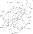
图1是本公开的未被限定的实施方式中的切削刀片的立体图。FIG. 1 is a perspective view of a cutting insert in a non-limiting embodiment of the present disclosure.
图2是针对图1所示的切削刀片,将三个第一贯通孔以及第一槽用虚线示出的立体图。Fig. 2 is a perspective view of the cutting insert shown in Fig. 1 , showing three first through-holes and first grooves with dotted lines.
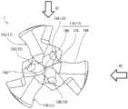
图3是从第一端侧观察图1所示的切削刀片的主视图。Fig. 3 is a front view of the cutting insert shown in Fig. 1 viewed from a first end side.
图4是针对图3所示的切削刀片,将三个第一贯通孔以及第一槽用虚线示出的主视图。4 is a front view of the cutting insert shown in FIG. 3 , showing three first through-holes and first grooves with dotted lines.
图5是从图3所示的A1方向观察图1所示的切削刀片的侧视图。Fig. 5 is a side view of the cutting insert shown in Fig. 1 viewed from the direction A1 shown in Fig. 3 .
图6是从图3所示的A2方向观察图1所示的切削刀片的侧视图。Fig. 6 is a side view of the cutting insert shown in Fig. 1 viewed from the direction A2 shown in Fig. 3 .
图7是从第二端侧观察图1所示的切削刀片的后视图。Fig. 7 is a rear view of the cutting insert shown in Fig. 1 viewed from the second end side.
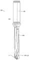
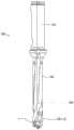
图8是表示本公开的未被限定的实施方式中的旋转刀具的侧视图。Fig. 8 is a side view showing a rotary cutter in a non-limiting embodiment of the present disclosure.
图9是从第一端侧观察图8所示的旋转刀具的主视图。Fig. 9 is a front view of the rotary cutter shown in Fig. 8 viewed from the first end side.
图10是从图9所示的A3方向观察图8所示的旋转刀具的侧视图。Fig. 10 is a side view of the rotary cutter shown in Fig. 8 viewed from the direction A3 shown in Fig. 9 .
图11是从图9所示的A4方向观察图8所示的旋转刀具的侧视图。Fig. 11 is a side view of the rotary cutter shown in Fig. 8 viewed from the direction A4 shown in Fig. 9 .
图12是表示本公开的未被限定的实施方式中的刀柄的立体图。Fig. 12 is a perspective view showing a handle in a non-limiting embodiment of the present disclosure.
图13是在图8所示的旋转刀具中将第一端侧的前端部分放大后的放大图。Fig. 13 is an enlarged view of a front end portion on a first end side of the rotary cutter shown in Fig. 8 .
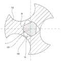
图14是图8所示的旋转刀具中的图13所示的D1-D1剖视图。Fig. 14 is a sectional view taken along line D1-D1 shown in Fig. 13 in the rotary cutter shown in Fig. 8 .
图15是图8所示的旋转刀具中的图13所示的D2-D2剖视图。Fig. 15 is a sectional view taken along line D2-D2 shown in Fig. 13 in the rotary cutter shown in Fig. 8 .
图16是图8所示的旋转刀具中的图13所示的D3-D3剖视图。Fig. 16 is a sectional view taken along line D3-D3 shown in Fig. 13 in the rotary cutter shown in Fig. 8 .
图17是表示本公开的未被限定的实施方式中的切削加工物的制造方法的工序的一例的概要图。FIG. 17 is a schematic diagram illustrating an example of steps of a method of manufacturing a machined product in a non-limiting embodiment of the present disclosure.
具体实施方式Detailed ways
以下,使用附图对本公开的未被限定的实施方式的切削刀片(以下,也简称为刀片)、旋转刀具以及切削加工物的制造方法进行详细说明。但是,为了方便说明,以下参照的各图仅简化示出了用于说明实施方式所需的主要构件。因而,刀片以及旋转刀具能够具备本说明书所参照的各图中未示出的任意的构成构件。另外,各图中的构件的尺寸,并非忠实表达实际的构成构件的尺寸以及各构件的尺寸比率等。Hereinafter, a cutting insert (hereinafter, simply referred to as an insert), a rotary cutter, and a method of manufacturing a cutting workpiece according to non-limiting embodiments of the present disclosure will be described in detail with reference to the drawings. However, for convenience of description, only main members necessary for describing the embodiments are simplified in each of the drawings referred to below. Therefore, the blade and the rotary cutter can be equipped with arbitrary structural members not shown in the drawings referred to in this specification. In addition, the dimensions of the members in the drawings do not faithfully express the dimensions of the actual constituent members, the dimensional ratios of the respective members, and the like.
(1.刀片的概要)(1.Summary of blade)
首先,使用图1~图7对实施方式的刀片1的概要进行说明。图1是刀片1的立体图。图2是针对图1所示的刀片1,将刀片1所具有的第一贯通孔13以及第一槽21用虚线示出的立体图。图3是从第一端10A侧观察刀片1的主视图。图4是针对图3所示的刀片1,将第一贯通孔13用虚线示出的主视图。图5是从图3所示的A1方向观察刀片1的俯视图。图6是从图3所示的A2方向观察刀片1的侧视图。图7是从第二端20A侧观察刀片1的后视图。First, the outline of the
如图1~7所示,刀片1沿着旋转轴X1从第一端10A朝向第二端20A延伸,并具有位于第一端10A侧的切削部10和位于第二端20A侧的轴部20。As shown in FIGS. 1 to 7 , the
轴部20沿着旋转轴X1延伸。轴部20能够在将刀片1安装于后述的刀柄102(参照图8~图12等)时,通过与设置于刀柄102的刀槽120嵌合而被固定,从而用作被刀柄102约束的部位。The
切削部10是在后述的切削加工(开孔加工)中,与作为加工对象的被切削件T(参照图17)接触的部位,且是在切削加工中具有主要作用的部位。The
刀片1在切削被切削件时能够绕旋转轴X1旋转,在图1等中绕旋转轴X1表示的箭头X2表示刀片1的旋转方向。将沿着旋转轴X1的方向上的切削部10的端部(即刀片1的前端)称为第一端10A,将沿着旋转轴X1的方向上的轴部20的远离切削部10一侧的端部(即刀片1的后端)称为第二端20A。The
轴部20也可以具有包含第二端20A的平面状的后端面22。关于轴部20的详细形状在后面叙述。另外,切削部10具有位于第二端20A侧的端部即端面12。该端面12是在将刀片1安装于刀柄102(参照图8等)时,与刀柄102中的设置有刀槽120(参照图12)的前端侧的端面130抵接的面。The
在本说明书中,“平坦”或者“平面”的记载意味着不是能够视觉确认的级别的曲面,或者不具有能够视觉确认的级别的凹凸。因此,记载为“平坦”或“平面”的面也可以允许在刀片1的制造中不可避免的程度的凹凸。具体而言,也可以具有例如50μm左右的表面粗糙度的凹凸。另外,“旋转轴”也可以表现为通过(i)第一端10A、(ii)轴部20的后端面22的中心或者大致中心的直线(中心线、中心轴)。In this specification, description of "flat" or "plane" means that it is not a curved surface of a visually recognizable level, or does not have a visually recognizable level of unevenness. Therefore, the surface described as "flat" or "plane" may allow unevenness to an unavoidable degree during the manufacture of the
轴部20的大小没有特别限定,在与旋转轴X1正交的方向上的轴部20的最大宽度例如可以设定为3~10mm左右。另外,轴部20的沿着旋转轴X1的方向(长度方向)的尺寸例如也可以设定为3~10mm左右。The size of the
切削部10的大小也没有特别限定。在与旋转轴X1平行地从第一端10A侧主视观察切削部10,并且描绘以旋转轴X1为中心点与切削部10的外缘相接的假想圆的情况下,该假想圆的直径例如可以设定为10~40mm左右。另外,切削部10的沿着旋转轴X1的方向上的、从第一端10A到端面12的尺寸例如可以设定为5~20mm左右。The size of the cutting
刀片1中的切削部10及轴部20可以分体形成,另外,也可以一体地形成。The cutting
(2.刀片的详细情况)(2. Details of blade)
在以往的切削刀片(参照例如专利文献1、2)中,贯通孔形成为与旋转轴平行或者相对于旋转轴朝向径向倾斜。通过使冷却液从这样形成的贯通孔流出,能够冷却被切削件。另一方面,在专利文献1或2所记载的切削刀片中,存在对切削刃的冷却效果不充分的可能性。In conventional cutting inserts (see, for example,
根据本公开的一方案,能够实现能够可对切削刃的冷却效果的切削刀片。According to one aspect of the present disclosure, it is possible to realize a cutting insert capable of cooling the cutting edge.
(切削部)(cutting part)
如图1~图7所示,在本例中,刀片1的切削部10具有位于第一端10A侧的三个切削刃11(11A、11B、11C)以及位于第二端20A侧的端面12。另外,切削部10具有三个第一贯通孔13(13A、13B、13C)。As shown in FIGS. 1 to 7, in this example, the cutting
三个第一贯通孔13(13A、13B、13C)分别从端面12朝向第一端10A在切削部10的内部延伸。三个第一贯通孔13(13A、13B、13C)分别具有位于第一端10A侧的第一开口14(14A、14B、14C)、以及位于第二端20A侧的第二开口15(15A、15B、15C)。三个第一贯通孔13(13A、13B、13C)分别从端面12朝向第一端10A侧在切削部10的内部延伸,三个第一开口14(14A、14B、14C)分别位于修磨面(后述)。Three first through-holes 13 ( 13A, 13B, 13C) respectively extend from the
在本例中,对具有三个切削刃11及三个第一贯通孔13的刀片1进行说明,但刀片1所具有的切削刃11及第一贯通孔13的数量没有特别限定。例如,刀片1也可以具有两个切削刃11,还可以具有四个以上的切削刃11。另外,例如,刀片1也可以具有两个第一贯通孔13,还可以具有四个以上的第一贯通孔13。刀片1基本上具有与切削刃11的数量相同数量的第一贯通孔13。In this example, an
在本例中,刀片1的旋转方向是如箭头X2所示,例如从第一端10A侧主视观察刀片1的情况下的逆时针的方向。关于本例的刀片1中的三个切削刃11,按照与箭头X2所示的旋转方向相反的、顺时针方向的顺序分别称为切削刃11A、切削刃11B、切削刃11C。另外,关于本例的刀片1中的三个第一贯通孔13,在顺时针方向上称为第一贯通孔13A、第一贯通孔13B、第一贯通孔13C。In this example, the rotation direction of the
在刀片1中,三个切削刃11及三个第一贯通孔13也可以位于以旋转轴X1为基准旋转对称的位置。在本例中,关于刀片1的切削部10,三个切削刃11及三个第一贯通孔13设置于以旋转轴X1为基准旋转对称的位置,并且具有相互类似的构成。因此,以下,对三个切削刃11及三个第一贯通孔13中的、切削刃11A及第一贯通孔13A进行详细说明,省略对其他的切削刃11B、11C及第一贯通孔13B、13C的说明。In the
如图3所示,切削刃11A具有从旋转轴X1的位置(第一端10A的位置)朝向切削部10的外周延伸的横刃16A、从横刃16A朝向外周延伸的修磨刃17A、以及从修磨刃17A朝向外周延伸的主切削刃18A。切削部10具有从修磨刃17A朝向第二端20A延伸的修磨面70A。As shown in FIG. 3 , the
第一贯通孔13A是在将刀片1安装于刀柄的状态下,从刀柄供给并流入第二开口15A的冷却液(冷却剂)的流路。冷却液通过第一贯通孔13A,从第一开口14A向刀片1的第一端10A侧喷射。具体而言,虽作为冷却液,没有特别限定,但例如可以举出水、油以及乳液等。The first through
在本例的刀片1中,第一贯通孔13A的第一开口14A及第二开口15A的位置关系如下。即,第一开口14A在箭头X2所示的旋转方向上位于第二开口15A的后方。在本例中,如箭头X2所示,刀片1的旋转方向是例如从第一端10A侧主视观察刀片1的情况下的逆时针的方向。第一开口14A也可以表现为相对于第二开口15A位于顺时针方向侧。In the
换言之,第一贯通孔13A设置为例如从第一端10A侧主视观察刀片1,以第一开口14A的位置为基准,在切削部10的内部形成相对于与旋转轴X1平行的方向而向刀片1的旋转方向(逆时针的方向)倾斜的流路。根据该构成,冷却液容易向相对于第一开口14(14A)位于旋转方向X2的后方的切削刃11(11A)喷射。另外,周向上的切削部10的强度的偏差容易变小。因此,容易提高刀片1的耐久性。In other words, the first through
另外,第一贯通孔13A的第一开口14A位于修磨面70A。根据该构成,切屑的排出性高,且冷却效率高。具体而言,与第一开口14A位于排出槽80A的情况相比,在第一开口14A位于修磨面70A的情况下,在排出槽80A中朝向第二端20A一方流动的切屑流不易被阻碍。In addition, the
另外,与第一开口14A位于例如后刀面的情况相比,在第一开口14A位于修磨面70A的情况下,由于第一开口14A相对于切削刃11A位于旋转方向X2的前方,因此冷却液的冷却效果较高。此外,与第一开口14A位于例如后刀面的情况相比,在第一开口14A位于修磨面70A的情况下,容易避免因设置有第一贯通孔13A而引起的切削刃11A的强度降低。即,切削刃11的耐久性高。In addition, compared with the case where the
另外,在本例的刀片1中,以从第一端10A侧主视观察刀片1,并且假想地透视第一贯通孔13的方式进行主视观察(正面透视),第一开口14A、第一贯通孔13B的第二开口15B也可以相互至少一部分重叠(参照图4)。在该情况下,由于在刀片1上旋转对称地设置有三个第一贯通孔13(13A、13B、13C),所以从第一端10A侧主视观察(正面透视)刀片1,第一贯通孔13A的第二开口15A成为与第一贯通孔13C的第一开口14C至少一部分重叠的位置。In addition, in the
在刀片1中,从第一端10A侧主视观察(正面透视)刀片1,第一开口14A的位置可以比第二开口15A的位置远离旋转轴X1。换言之,从第一端10A侧主视观察刀片1,第一开口14A与旋转轴X1之间的距离L1可以比第二开口15A与旋转轴X1之间的距离L2长。距离L1是将第一开口14A的周缘中的靠近旋转轴X1的缘部与旋转轴X1连结,且相对于旋转轴X1正交的线段的长度。距离L2是将第二开口15A的周缘中的靠近旋转轴X1的缘部与旋转轴X1连结,且相对于旋转轴X1正交的线段的长度。In the
由于横刃16A那样的从旋转轴X1延伸的切削刃11A的部位的切削速度较慢,因此在切削加工时容易对切削刃11A的上述部位附近施加较大的切削负载。然而,在第一开口14A相对地远离旋转轴X1的情况下(第一开口14A的位置距旋转轴X1较远的情况下),容易确保横刃16A那样的从旋转轴X1延伸的切削刃11A的部位附近处的切削部10的壁厚较厚。因此,切削部10的耐久性高。Since the cutting speed of the portion of the
另外,在第一开口14A的位置比第二开口15A的位置更远离旋转轴X1的情况下(即,L1>L2的情况下),从第一开口14A喷射的冷却液容易朝向外周流动。因此,容易冷却切削刃11的大范围。即,冷却液的冷却效果好。In addition, when the position of the
另外,从第一端10A侧主视观察刀片1,与三个第一贯通孔13A、13B、13C对应的三个第一开口14(14A、14B、14C)也可以不以旋转轴X1为中心旋转对称。具体而言,从第一端10A侧主视观察刀片1,从旋转轴X1到三个第一开口14(14A、14B、14C)的距离也可以相互不同。例如,从旋转轴X1到第一开口14A的距离也可以不同于从旋转轴X1到第一开口14B的距离。In addition, when the
根据上述构成,容易减少从旋转轴X1朝向切削部10的外周延伸的切削刃11的径向上的冷却偏差。因此,冷却液的冷却效果好。According to the above configuration, it is easy to reduce the cooling variation in the radial direction of the
切削部10具有从主切削刃18A朝向第二端20A延伸的排出槽80A。排出槽80A中的沿着主切削刃18A的部分可以作为前刀面发挥功能。排出槽80A与修磨面70A相邻。排出槽80A是用于提高由切削刃11A切削的被切削件的切屑的排出性的槽。在本例的刀片1中,第二开口15B也可以位于远离排出槽80A与端面12相交的棱线81A(参照图7)的位置。The cutting
根据上述构成,由于减少了冷却液向排出槽80A的泄漏,因此能够稳定地从第一开口14A喷射冷却液。According to the above configuration, since the leakage of the cooling liquid to the
刀片1以与三个切削刃11中的三个主切削刃18(主切削刃18A、主切削刃18B、主切削刃18C)分别对应的方式具有三个排出槽80(排出槽80A、排出槽80B、排出槽80C)。将端面12与排出槽80B相交的棱线称为棱线81B,将端面12与排出槽80C相交的棱线称为棱线81C。在本例的刀片1中,第二开口15A位于远离棱线81C的位置,第二开口15C位于远离棱线81B的位置。由此,与上述相同,能够稳定地从第一开口14B及第一开口14C喷射冷却液。
(轴部)(shaft)
本例的刀片1中的轴部20也可以是以下的形状,能够嵌合固定于刀柄102的刀槽120(参照图12),并且在这样固定的状态下冷却液能够在刀槽120与轴部20之间流通。The
即,轴部20也可以具有从形成于切削部10的端面12的三个第二开口15分别向朝向第二端20A的方向延伸的三个流路面23。流路面23形成冷却液的流路的一部分。流路面23可以是平面状或大致平面状,也可以是向旋转轴X1方向凹陷的曲面形状。That is, the
轴部20可以在两个流路面23之间具有与圆柱的外周面相当的形状的弯曲面24,在本例中,具有三个弯曲面24。轴部20大致上例如也可以是具有在圆柱的外周面附近处从三个位置切出比较小型的半椭圆柱而形成的、三个流路面23及三个弯曲面24的形状。对于轴部20,也可以在弯曲面24与后端面22之间实施倒角加工。The
另外,圆柱形状的轴部20的直径(与旋转轴X1正交的方向的宽度)也可以在从第一端10A侧朝向第二端10B侧未必恒定。例如,轴部20可以如上述那样对第二端10B侧的端部实施倒角加工,另外,也可以在第一端10A侧的端部(切削部10与轴部20的边界)形成圆角。而且,轴部20的直径也可以从第一端10A侧的端部到第二端10B侧的端部逐渐变大。直接而言,轴部20也可以是圆锥台形状。In addition, the diameter (the width in the direction perpendicular to the rotation axis X1 ) of the
在刀片1中,三个流路面23也可以位于以旋转轴X1为基准旋转对称的位置。在本例中,刀片1中的轴部20具有三个流路面23,但并不限定于此。流路面23只要设置为与第一贯通孔13相同的数量即可。In the
另外,轴部20也可以在流路面23的一部分具有从第一贯通孔13A向朝向第二端20A的方向延伸的第一槽21。另外,第一槽21可以与第一贯通孔13A平行。典型的是,在切削部10的制造过程中,在通过开孔加工形成第一贯通孔13时,通过用于该开孔加工的工具与流路面23的一部分接触而形成第一槽21。In addition, the
在轴部20具有第一槽21的情况下,能够使冷却液从轴部20中的流路(流路面23)向第一贯通孔13A顺畅地流入。特别是,在第一槽21相对于第一贯通孔13A平行或大致平行地延伸的情况下,能够使冷却液进一步顺畅地流入第一贯通孔13A。When the
(3.旋转刀具的构成)(3. Composition of rotary cutter)
接下来,对于本公开的一例中的旋转刀具100,使用图8~16进行说明。图8是表示旋转刀具100的侧视图。图9是从第一端10A侧观察旋转刀具100的主视图。图10是从图9所示的A3方向观察旋转刀具100的俯视图。图11是从图9所示的A4方向观察旋转刀具100的侧视图。图12是表示刀柄102的立体图。图13是在旋转刀具100中放大了第一端10A侧的前端部分的放大图。图14是表示旋转刀具100中的图13所示的D1-D1剖面的剖视图。图15是表示旋转刀具100中的图13所示的D2-D2剖面的剖视图。图16是表示旋转刀具100中的图13所示的D3-D3剖面的剖视图。Next, a
如图8~图16所示,一例中的旋转刀具100是刀片1与刀柄102分体形成且在刀柄102的前端部分安装刀片1的所谓刀片型的钻头。旋转刀具100具有旋转轴X1,以旋转轴X1为中心旋转。As shown in FIGS. 8 to 16 , the
本例中的旋转刀具100是安装有一个刀片1的单芯片型的钻头,但具备刀片1的旋转刀具并不限定于单芯片型的钻头。另外,旋转刀具不限于相对于被切削件沿旋转轴X1的方向移动而进行开孔加工的钻头,也可以是一边旋转一边沿任意的方向移动而能够对被切削件进行铣削的工具。作为具备刀片1的旋转刀具,例如可以举出立铣刀及铣削刀具等。The
刀柄102可以具有沿着旋转轴X1延伸的、柄部103以及主体104。柄部103也可以是沿着旋转轴X1延伸的棒形状,例如是由机床把持的部位。The
主体104在侧面具有用于排出被切削物T的切屑的排出槽110。另外,主体104具有在前端侧开口的刀槽120。刀片1的轴部20安装于刀槽120。刀片1可以通过省略图示的例如螺钉安装于刀柄102(主体104)。The
主体104的靠刀片1侧的前端的端面130与刀片1的端面12抵接。排出槽110与刀片1的排出槽80连接。The
刀柄102在柄部103及主体104的内部具有沿着旋转轴X1延伸的第二贯通孔150。第二贯通孔150成为冷却液的流路,第二贯通孔150与刀槽120连通。The
旋转刀具100通过轴部20具有流路面23,从而在刀槽120的空间内在轴部20与刀槽120的内周壁面之间产生间隙。因此,通过第二贯通孔150到达轴部20的后端面22的冷却液能够通过所述间隙朝向第二开口15流动。The
旋转刀具100也可以在刀槽120的内周壁面中的、与流路面23对置的部分具有向远离旋转轴X1方向凹陷的曲面状的第二槽125。第二槽125也可以设置为与轴部20中的流路面23的数量相同的数量。流路面23以及第二槽125在刀槽120与轴部20之间形成间隙流路128。通过具有第二槽125,能够增大间隙流路128的体积。另外,刀槽120的内周壁面中的第二槽125以外的部分与弯曲面24抵接。由此,能够稳定地固定安装于刀槽120的轴部20,并且冷却液容易在间隙流路128流动。The
如图15所示,通过在流路面23的一部分形成第一槽21,能够进一步增大俯视时的间隙流路128的面积。As shown in FIG. 15 , by forming the
冷却液通过第二贯通孔150向间隙流路128供给,通过间隙流路128到达第二开口15之后,从第二开口15通过第一贯通孔13而从第一开口14释放出。从第一开口14释放出的冷却液与切削刃11接触,冷却切削刃11。然后,冷却液通过排出槽80及排出槽110而被排出到被切削件的加工孔的外部。The coolant is supplied to the
<切削加工物的制造方法><Manufacturing method of machined product>
接下来,使用图17对本公开的未被限定的实施方式中的切削加工物的制造方法进行说明。图17是表示本公开的未被限定的实施方式中的切削加工物的制造方法的工序的概要图。以下,对使用旋转刀具100切削被切削物T,制作切削加工物U的方法进行说明。Next, a method of manufacturing a machined product in a non-limiting embodiment of the present disclosure will be described using FIG. 17 . FIG. 17 is a schematic diagram illustrating steps of a method of manufacturing a machined product in an unrestricted embodiment of the present disclosure. Hereinafter, a method of cutting the workpiece T by using the
根据本公开的未被限定的实施方式中的切削加工物U的制造方法可以包括以下的工序。即,The manufacturing method of the machined object U in the non-limiting embodiment according to the present disclosure may include the following steps. Right now,
(1)使旋转刀具100旋转的工序;(1) A process of rotating the
(2)使旋转刀具100被切削件T接触的工序;以及(2) A process of bringing the
(3)使旋转刀具100从被切削件T离开的工序。(3) A step of separating the
更具体而言,首先,如图17的附图标记1701所示的图那样,在旋转刀具100的正下方准备被切削物T,使安装于机床的旋转刀具100以旋转轴X1为中心旋转。作为被切削物T可列举如铝、碳钢、合金钢、不锈钢、铸铁及非铁金属等。More specifically, first, as shown by
接下来,如图17的附图标记1702所示的图那样,使旋转刀具100与被切削物T接近,使旋转刀具100与被切削件T接触。由此,被切削件T被刀片1所具有的切削刃11切削,形成加工孔V。被切削的被切削件T的切屑从刀片1的排出槽80通过刀柄102的排出槽110而被排出到外部。旋转刀具100与被切削物T只要相对接近即可,其方法没有特别限定。例如可以使旋转刀具100朝向固定的被切削物T移动,也可以使被切削物T相对于位置固定而旋转的旋转刀具100移动。Next, as shown by
接着,如图17的附图标记1703所示的图那样,使旋转刀具100远离被切削件T。由此,制作形成有加工孔V的被切削物T即切削加工物U。Next, the
<变形例><Modification>
在上述的实施方式中,对刀片1与刀柄102进行组合而构成的所谓刀片型的旋转刀具100进行了说明。其中,旋转刀具100的构成并不局限于此,例如当然也可以是刀片1与刀柄102一体地形成的所谓整体型的旋转刀具。In the above-mentioned embodiment, the so-called blade-
(补充说明事项)(Supplementary Explanation Matters)
以上,对于本公开的发明,基于各附图及实施例进行了说明。但是,本公开的发明不受上述各实施方式限定。即,本公开的发明可以在本公开所示的范围内进行各种变更,不同的实施方式各自公开的技术手段经适宜组合而得到的实施方式也包括在本公开的发明的技术范围内。换言之,应当注意的是,只要是本领域技术人员,基于本公开进行各种变形或者修改很容易。另外,要留意这些变形或修改包括在本公开的范围内。As mentioned above, the invention of this disclosure was demonstrated based on each drawing and an Example. However, the invention of the present disclosure is not limited to each of the above-mentioned embodiments. That is, the invention of the present disclosure can be modified variously within the scope of the disclosure, and embodiments obtained by appropriately combining the technical means disclosed in different embodiments are also included in the technical scope of the invention of the present disclosure. In other words, it should be noted that various variations or modifications based on the present disclosure are easy for those skilled in the art. In addition, it is to be noted that such variations or modifications are included in the scope of the present disclosure.
附图标记说明Explanation of reference signs
1刀片(切削刀片)1 blade (cutting blade)
10切削部10 cutting part
10A第一端10A first end
11、11A、11B、11C切削刃11, 11A, 11B, 11C cutting edge
12、130端面12, 130 end face
13、13A~13C第一贯通孔13. 13A~13C first through hole
14、14A~14C第一开口14. 14A~14C first opening
15、15A~15C第二开口15. 15A~15C second opening
16A横刃16A chisel edge
17A修磨刃17A sharpening
18、18A~18C主切削刃18, 18A~18C main cutting edge
20轴部20 axis
20A第二端20A second terminal
21第一槽21 first slot
70A修磨面70A grinding surface
80、80A~80C、110排出槽80, 80A~80C, 110 discharge tank
81A~81C棱线81A~81C ridge line
100旋转刀具100 rotary cutters
102刀柄102 handle
125第二槽125 second slot
150第二贯通孔150 second through hole
X1旋转轴X1 rotation axis
X2箭头(旋转方向)。X2 arrow (direction of rotation).
Claims (10)
Translated fromChineseApplications Claiming Priority (3)
| Application Number | Priority Date | Filing Date | Title |
|---|---|---|---|
| JP2020-140376 | 2020-08-21 | ||
| JP2020140376 | 2020-08-21 | ||
| PCT/JP2021/030562WO2022039258A1 (en) | 2020-08-21 | 2021-08-20 | Cutting insert, rotary tool, and method for manufacturing cut product |
Publications (2)
| Publication Number | Publication Date |
|---|---|
| CN116209534Atrue CN116209534A (en) | 2023-06-02 |
| CN116209534B CN116209534B (en) | 2025-09-23 |
Family
ID=80322981
Family Applications (1)
| Application Number | Title | Priority Date | Filing Date |
|---|---|---|---|
| CN202180055269.8AActiveCN116209534B (en) | 2020-08-21 | 2021-08-20 | Cutting insert, rotary tool, and method for manufacturing cut product |
Country Status (5)
| Country | Link |
|---|---|
| US (1) | US20230321733A1 (en) |
| JP (1) | JP7465981B2 (en) |
| CN (1) | CN116209534B (en) |
| DE (1) | DE112021004391T5 (en) |
| WO (1) | WO2022039258A1 (en) |
Citations (5)
| Publication number | Priority date | Publication date | Assignee | Title |
|---|---|---|---|---|
| CN1190917A (en)* | 1995-07-14 | 1998-08-19 | 克纳门特尔-赫特尔刀具及硬质材料股份有限公司 | Drills with coolant channels |
| CN101360578A (en)* | 2006-06-19 | 2009-02-04 | 彗星集团控股有限公司 | An interface between two components of a rotating tool system |
| CN102378662A (en)* | 2009-03-10 | 2012-03-14 | 钴碳化钨硬质合金公司 | Cutting tool for a machine tool |
| CN104096884A (en)* | 2013-04-03 | 2014-10-15 | 钴碳化钨硬质合金公司 | Coupling structure e.g. cutting head for rotary tool e.g. drilling tool, has coupling pin with clamping faces and stop surfaces that are arranged in different dispensing areas |
| CN110153482A (en)* | 2018-02-14 | 2019-08-23 | 肯纳金属公司 | Cutting inserts with internal coolant channels |
Family Cites Families (10)
| Publication number | Priority date | Publication date | Assignee | Title |
|---|---|---|---|---|
| SE517817C2 (en)* | 2000-02-11 | 2002-07-16 | Sandvik Ab | Chip separation machining tool with groove-shaped coolant ducts in the end surface |
| US7036539B2 (en)* | 2002-09-18 | 2006-05-02 | Black & Decker Inc. | Air cooled router bit |
| DE102007050471A1 (en) | 2007-10-23 | 2009-04-30 | MAPAL Fabrik für Präzisionswerkzeuge Dr. Kress KG | Tool for machining workpieces |
| KR101014027B1 (en)* | 2010-08-02 | 2011-02-14 | 한국야금 주식회사 | Indexable Drill |
| US20140255116A1 (en) | 2013-03-09 | 2014-09-11 | Kennametal Inc. | Rotary cutting tool, replaceable cutting insert and method of making replaceable cutting insert |
| DE102014204700B4 (en)* | 2014-03-13 | 2022-02-17 | Kennametal Inc. | Rotary tool, in particular drilling tool and method for producing a rotary tool |
| US9902002B2 (en)* | 2014-09-24 | 2018-02-27 | Kennametal Inc. | Reamers with radially extending flutes |
| EP3372330B1 (en)* | 2017-03-10 | 2023-01-04 | Seco Tools Ab | Tool tip |
| US10799958B2 (en)* | 2017-08-21 | 2020-10-13 | Kennametal Inc. | Modular rotary cutting tool |
| TWI786325B (en)* | 2018-10-04 | 2022-12-11 | 以色列商艾斯卡公司 | Cutting head having tip portion with radially extending front cutting edges provided with both negative and positive rake angles, and rotary cutting tool |
- 2021
- 2021-08-20WOPCT/JP2021/030562patent/WO2022039258A1/ennot_activeCeased
- 2021-08-20USUS18/042,289patent/US20230321733A1/enactivePending
- 2021-08-20CNCN202180055269.8Apatent/CN116209534B/enactiveActive
- 2021-08-20JPJP2022544020Apatent/JP7465981B2/enactiveActive
- 2021-08-20DEDE112021004391.9Tpatent/DE112021004391T5/enactivePending
Patent Citations (5)
| Publication number | Priority date | Publication date | Assignee | Title |
|---|---|---|---|---|
| CN1190917A (en)* | 1995-07-14 | 1998-08-19 | 克纳门特尔-赫特尔刀具及硬质材料股份有限公司 | Drills with coolant channels |
| CN101360578A (en)* | 2006-06-19 | 2009-02-04 | 彗星集团控股有限公司 | An interface between two components of a rotating tool system |
| CN102378662A (en)* | 2009-03-10 | 2012-03-14 | 钴碳化钨硬质合金公司 | Cutting tool for a machine tool |
| CN104096884A (en)* | 2013-04-03 | 2014-10-15 | 钴碳化钨硬质合金公司 | Coupling structure e.g. cutting head for rotary tool e.g. drilling tool, has coupling pin with clamping faces and stop surfaces that are arranged in different dispensing areas |
| CN110153482A (en)* | 2018-02-14 | 2019-08-23 | 肯纳金属公司 | Cutting inserts with internal coolant channels |
Also Published As
| Publication number | Publication date |
|---|---|
| CN116209534B (en) | 2025-09-23 |
| DE112021004391T5 (en) | 2023-06-01 |
| JPWO2022039258A1 (en) | 2022-02-24 |
| WO2022039258A1 (en) | 2022-02-24 |
| JP7465981B2 (en) | 2024-04-11 |
| US20230321733A1 (en) | 2023-10-12 |
Similar Documents
| Publication | Publication Date | Title |
|---|---|---|
| JP5013435B2 (en) | Ball end mill | |
| JP7216698B2 (en) | Manufacturing method for cutting tools and cut products | |
| JP4814890B2 (en) | Cutting insert, milling tool and cutting method | |
| US20100221076A1 (en) | Cutting tool and cutting insert | |
| JP5614511B2 (en) | Ball end mill and insert | |
| JP2007030074A (en) | Radius end mill and cutting method | |
| KR20080027733A (en) | Tool for chip removal machining and cutting inserts therefor | |
| CN113226606B (en) | Rotary tools with coolant holes | |
| JP2010105119A (en) | Drill reamer | |
| WO2019073752A1 (en) | Rotary cutting tool | |
| JP2011073129A (en) | Boring drill | |
| WO2020080397A1 (en) | Reamer with oil hole | |
| US10821526B2 (en) | Rotary tool and method for manufacturing machined product | |
| JP2010076088A (en) | Cutting tool | |
| JP7314418B2 (en) | Drill | |
| JP2019115939A (en) | Rotary tool and manufacturing method of cutting workpiece | |
| CN116209534A (en) | Cutting insert, rotary tool and method for manufacturing cutting workpiece | |
| JP2016147328A (en) | drill | |
| JP7727830B2 (en) | Drill and cutting process | |
| JP2008173727A (en) | Drill | |
| JP7488349B2 (en) | Method for manufacturing cutting insert, rotary tool, and machined product | |
| JP2003275913A (en) | Drill | |
| JP5564958B2 (en) | Replaceable cutting edge grooving tool and end face grooving method | |
| CN115666831A (en) | drill | |
| JP2008044040A (en) | Rotary cutting tool |
Legal Events
| Date | Code | Title | Description |
|---|---|---|---|
| PB01 | Publication | ||
| PB01 | Publication | ||
| SE01 | Entry into force of request for substantive examination | ||
| SE01 | Entry into force of request for substantive examination | ||
| GR01 | Patent grant | ||
| GR01 | Patent grant |