CN116206847A - A cooling system and a superconducting magnet system - Google Patents
A cooling system and a superconducting magnet systemDownload PDFInfo
- Publication number
- CN116206847A CN116206847ACN202310343344.1ACN202310343344ACN116206847ACN 116206847 ACN116206847 ACN 116206847ACN 202310343344 ACN202310343344 ACN 202310343344ACN 116206847 ACN116206847 ACN 116206847A
- Authority
- CN
- China
- Prior art keywords
- low
- temperature
- heat pipe
- pulsating heat
- thermal switch
- Prior art date
- Legal status (The legal status is an assumption and is not a legal conclusion. Google has not performed a legal analysis and makes no representation as to the accuracy of the status listed.)
- Pending
Links
Images


Classifications
- H—ELECTRICITY
- H01—ELECTRIC ELEMENTS
- H01F—MAGNETS; INDUCTANCES; TRANSFORMERS; SELECTION OF MATERIALS FOR THEIR MAGNETIC PROPERTIES
- H01F6/00—Superconducting magnets; Superconducting coils
- H01F6/04—Cooling
- H—ELECTRICITY
- H01—ELECTRIC ELEMENTS
- H01F—MAGNETS; INDUCTANCES; TRANSFORMERS; SELECTION OF MATERIALS FOR THEIR MAGNETIC PROPERTIES
- H01F6/00—Superconducting magnets; Superconducting coils
Landscapes
- Engineering & Computer Science (AREA)
- Power Engineering (AREA)
- Containers, Films, And Cooling For Superconductive Devices (AREA)
Abstract
Translated fromChinese
Description
Translated fromChinese技术领域technical field
本发明涉及超导磁体技术领域,尤其涉及一种冷却系统及超导磁体系统。The invention relates to the technical field of superconducting magnets, in particular to a cooling system and a superconducting magnet system.
背景技术Background technique
超导的广泛应用一直与低温密不可分,只有将磁体冷却至超导转变温度以下才能实现超导特性,一旦超过超导转变温度,失超产生的巨大焦耳热可能损坏超导磁体结构,甚至引发爆炸事故。目前应用最广泛的超导磁体为低温超导磁体,其超导转变温度非常低,如NbTi的超导转变温度为9.6K,Nb3Sn的超导转变温度为18.1K,即使被称为高温超导磁体的液氮温区超导磁体的超导转变温度也需要近似77K。因此,保证超导磁体稳定运行在低温环境是超导技术应用的关键。The wide application of superconductivity has always been inseparable from low temperature. Only by cooling the magnet below the superconducting transition temperature can superconducting properties be realized. Once the superconducting transition temperature is exceeded, the huge Joule heat generated by the quench may damage the structure of the superconducting magnet, and even cause Explosion accident. At present, the most widely used superconducting magnets are low-temperature superconducting magnets, whose superconducting transition temperature is very low. For example, the superconducting transition temperature of NbTi is 9.6K, and the superconducting transition temperature of Nb3 Sn is 18.1K. The superconducting transition temperature of the superconducting magnet in the liquid nitrogen temperature region of the superconducting magnet also needs to be approximately 77K. Therefore, ensuring the stable operation of superconducting magnets in a low temperature environment is the key to the application of superconducting technology.
随着小型制冷机技术的发展,使用制冷机直接冷却超导磁体系统的应用越来越广泛,其相对传统低温液体浸泡法,具有无液氦消耗、成本低、体积小、结构紧凑及易于使用和维护等优势。典型的制冷机冷却系统包括被冷却负载、防辐射冷屏、制冷机、真空容器及其他附件,防辐射冷屏与制冷机一级冷头连接,被冷却负载与二级冷头连接。冷却系统运行时,制冷机二级冷头将会达到闭式循环制冷机的最低温度。With the development of small refrigerator technology, the use of refrigerators to directly cool superconducting magnet systems is becoming more and more widely used. Compared with the traditional low-temperature liquid immersion method, it has the advantages of no liquid helium consumption, low cost, small size, compact structure and easy to use. and maintenance advantages. A typical cooling system of a refrigerator includes a cooled load, a radiation-proof cold shield, a refrigerator, a vacuum container and other accessories. The radiation-proof cold shield is connected to the primary cold head of the refrigerator, and the cooled load is connected to the secondary cold head. When the cooling system is running, the chiller secondary cold head will reach the minimum temperature of the closed cycle chiller.
在超导磁体系统的部分应用场景中,如应用于太空天文望远镜时,由于系统维护较为困难,制冷系统中通常设置有制冷机冗余系统,通过在每个冗余的制冷机之间分割运行时间,减少每台制冷机的占空比来达到延长制冷机单元的寿命,或者在某一制冷机故障时,保证被冷却负载能够由剩余制冷机冷却而保持正常工作。因此,低温热开关位于被冷却负载和制冷机之间,当制冷机工作时,热开关导通,热阻较小,以允许在设计温度下有效祛除热负荷;当制冷机停止工作或失效时,热开关关闭,热阻较大,从而阻断该制冷机与被冷却负载之间的传热路径,阻止热量由制冷机流向温度较低的负载,使低温系统的运行不受影响。In some application scenarios of the superconducting magnet system, such as space astronomical telescopes, due to the difficulty of system maintenance, the refrigeration system is usually equipped with a refrigerator redundant system, by dividing the operation between each redundant refrigerator Time, reduce the duty cycle of each refrigerator to prolong the life of the refrigerator unit, or when a refrigerator fails, ensure that the cooled load can be cooled by the remaining refrigerators to maintain normal operation. Therefore, the low-temperature thermal switch is located between the cooled load and the refrigerator. When the refrigerator is working, the thermal switch is turned on and the thermal resistance is small to allow the heat load to be effectively removed at the design temperature; when the refrigerator stops working or fails , the thermal switch is closed, and the thermal resistance is large, thereby blocking the heat transfer path between the refrigerator and the cooled load, preventing heat from flowing from the refrigerator to the load with a lower temperature, so that the operation of the low temperature system will not be affected.
低温热开关通常包括机械接触式热开关、超导式热开关、气隙式热开关和磁阻式热开关等。机械接触式热开关是利用可移动表面的接触或断开实现热开关状态的切换,其具有工作温区不受限制且可完全断开的优点,但是热导受压力限制难以做到较高,且需要设置额外的驱动结构驱动热开关移动,设计难度较大,且占地空间较大;超导式热开关的原理是利用超导材料在正常态和超导态的热导率差异进行热开关的切换,其在导通时导热系数较高,但是仅适用于0.5K以下温区,且需要额外施加作用于超导式热开关的磁场,导致系统复杂性和系统成本增加,同时,对热开关施加磁场时的磁热效应也会产生热量,在热开关断开时还会存在漏热;气隙式热开关的工作原理是在温度较低的一侧放置吸附剂,当该侧温度较低时,吸附剂吸附气体,使叶片间隙气压较低,热开关处于断开状态,随着该侧温度升高,吸附剂解吸,气体进入间隙,热开关处于导通状态,其可被动驱动,但是预设工作温度范围要求较高,且需要精密制造,成本较高;磁阻式热开关原理是利用某些金属的磁阻效应,当施加磁场时,受到洛伦兹力作用,载热电子的运动将受到抑制,材料的热导率最低可降至仅由声子导热的水平,因此其开关比较大,但磁阻式热开关仅限于极低温应用,需要大磁场和相应的电磁铁,成本较高,占地空间较大,同时磁阻材料过脆,易于损坏,导致加工和维护成本增加。Low temperature thermal switches generally include mechanical contact thermal switches, superconducting thermal switches, air gap thermal switches, and magnetoresistive thermal switches. The mechanical contact thermal switch uses the contact or disconnection of the movable surface to switch the thermal switch state. It has the advantages of unlimited working temperature range and complete disconnection, but it is difficult to achieve high thermal conductivity due to the pressure limit. And it is necessary to set up an additional driving structure to drive the thermal switch to move, which is difficult to design and takes up a large space; the principle of the superconducting thermal switch is to use the difference in thermal conductivity of the superconducting material in the normal state and the superconducting state to conduct heat transfer. The switching of the switch has a high thermal conductivity when it is turned on, but it is only suitable for the temperature range below 0.5K, and an additional magnetic field acting on the superconducting thermal switch is required, which increases the complexity and cost of the system. At the same time, the The magneto-caloric effect when the thermal switch applies a magnetic field will also generate heat, and there will be heat leakage when the thermal switch is turned off; the working principle of the air-gap thermal switch is to place an adsorbent on the side with a lower temperature. When it is low, the adsorbent adsorbs gas, so that the air pressure in the blade gap is low, and the thermal switch is in the off state. As the temperature on this side rises, the adsorbent desorbs, the gas enters the gap, and the thermal switch is in the conductive state, which can be driven passively. However, the preset operating temperature range is relatively high, and it requires precision manufacturing, and the cost is high; the principle of the magnetoresistive thermal switch is to use the magnetoresistance effect of some metals. When a magnetic field is applied, it is subjected to the Lorentz force, and the hot electron The movement of the material will be suppressed, and the thermal conductivity of the material can be reduced to the level where only phonons conduct heat, so its switch is relatively large, but the magnetoresistive thermal switch is limited to extremely low temperature applications, requiring a large magnetic field and corresponding electromagnets, The cost is high, and the floor space is large. At the same time, the magnetoresistive material is too brittle and easy to be damaged, resulting in increased processing and maintenance costs.
发明内容Contents of the invention
本发明的一个目的在于提供一种冷却系统,其能够提高冷却系统的运行安全性和稳定性,且提高冷却系统的结构紧凑性,降低冷却系统的设置成本。An object of the present invention is to provide a cooling system, which can improve the operation safety and stability of the cooling system, improve the compactness of the cooling system, and reduce the installation cost of the cooling system.
本发明的另一个目的在于提供一种超导磁体系统,其能够提高超导磁体系统的结构紧凑性,且能够提高超导磁体系统的运行效率、运行安全性和运行可靠性。Another object of the present invention is to provide a superconducting magnet system, which can improve the structural compactness of the superconducting magnet system, and can improve the operating efficiency, operating safety and operating reliability of the superconducting magnet system.
为实现上述目的,本发明采用下述技术方案:To achieve the above object, the present invention adopts the following technical solutions:
一种冷却系统,用于冷却被冷却负载,所述冷却系统包括真空罩、制冷机及第一热开关,所述制冷机设置有至少两个,且每个所述制冷机均具有冷头,所述第一热开关与所述制冷机一一对应设置,所述被冷却负载、所述冷头及所述第一热开关均位于所述真空罩内;A cooling system for cooling a load to be cooled, the cooling system includes a vacuum cover, a refrigerator and a first thermal switch, at least two of the refrigerators are provided, and each of the refrigerators has a cold head, The first thermal switch is arranged in one-to-one correspondence with the refrigerator, and the load to be cooled, the cold head and the first thermal switch are all located in the vacuum cover;
所述第一热开关包括第一低温脉动热管,所述第一低温脉动热管的蒸发段与所述被冷却负载连接,所述第一低温脉动热管的冷凝段与所述冷头连接,当所述冷头处于最终制冷温度时,所述第一低温脉动热管内的第一工质处于两相流状态。The first thermal switch includes a first low-temperature pulsating heat pipe, the evaporation section of the first low-temperature pulsating heat pipe is connected to the cooled load, and the condensation section of the first low-temperature pulsating heat pipe is connected to the cold head. When the cold head is at the final refrigeration temperature, the first working medium in the first low-temperature pulsating heat pipe is in a two-phase flow state.
作为一种制冷系统的可选技术方案,所述冷却系统还包括一级防辐射屏,所述一级防辐射屏悬设于所述真空罩内,所述被冷却负载位于所述一级防辐射屏内部,所述冷头与所述一级防辐射屏热连接。As an optional technical solution of the refrigeration system, the cooling system further includes a primary radiation protection screen, the primary radiation protection screen is suspended in the vacuum cover, and the cooled load is located in the primary radiation protection screen. Inside the radiation shield, the cold head is thermally connected to the primary radiation shield.
作为一种制冷系统的可选技术方案,每个所述制冷机均包括两个冷头,两个所述冷头分别为一级冷头和二级冷头,所述第一低温脉动热管的冷凝段与所述二级冷头连接,所述一级冷头与所述一级防辐射屏热连接;As an optional technical solution of the refrigeration system, each of the refrigerators includes two cold heads, the two cold heads are respectively a primary cold head and a secondary cold head, and the first low-temperature pulsating heat pipe The condensation section is connected to the secondary cold head, and the primary cold head is thermally connected to the primary radiation shield;
所述冷却系统还包括第二热开关,所述第二热开关包括第二低温脉动热管,所述第二低温脉动热管的冷凝段与所述一级冷头热连接,所述第二低温脉动热管的蒸发段与所述被冷却负载热连接,所述第二低温脉动热管内的三相点临界高于所述一级冷头的最终制冷温度。The cooling system also includes a second thermal switch, the second thermal switch includes a second low-temperature pulsating heat pipe, the condensation section of the second low-temperature pulsating heat pipe is thermally connected to the primary cold head, and the second low-temperature pulsating heat pipe The evaporating section of the heat pipe is thermally connected with the load to be cooled, and the triple point in the second low temperature pulsating heat pipe is critically higher than the final refrigeration temperature of the primary cold head.
作为一种制冷系统的可选技术方案,所述一级防辐射屏内部悬设有二级防辐射屏,所述被冷却负载位于所述二级防辐射屏内部,所述二级冷头与所述二级防辐射屏热连接。As an optional technical solution of the refrigeration system, a secondary radiation protection screen is suspended inside the primary radiation protection screen, the load to be cooled is located inside the secondary radiation protection screen, and the secondary cold head and The secondary radiation shield is thermally connected.
作为一种制冷系统的可选技术方案,所述二级防辐射屏通过第三热开关与所述二级冷头连接,所述第三热开关包括第三低温脉动热管,所述第三低温脉动热管的蒸发段与所述二级防辐射屏热连接,所述第三低温脉动热管的冷凝段与所述二级冷头热连接,当所述二级冷头处于最终制冷温度时,所述第三低温脉动热管内的第三工质处于气液两相流状态。As an optional technical solution of the refrigeration system, the secondary radiation shield is connected to the secondary cold head through a third thermal switch, the third thermal switch includes a third low-temperature pulsating heat pipe, and the third low-temperature The evaporation section of the pulsating heat pipe is thermally connected to the secondary radiation shield, and the condensation section of the third low-temperature pulsating heat pipe is thermally connected to the secondary cold head. When the secondary cold head is at the final cooling temperature, the The third working medium in the third low-temperature pulsating heat pipe is in a gas-liquid two-phase flow state.
作为一种制冷系统的可选技术方案,所述冷头通过第四热开关与所述一级防辐射屏热连接,所述第四热开关包括第四低温脉动热管,所述第四低温脉动热管的蒸发段与所述一级防辐射屏热连接,所述第四低温脉动热管的冷凝段与所述冷头热连接,当所述冷头处于最终制冷温度时,所述第四低温脉动热管内的第四工质处于气液两相流状态。As an optional technical solution of the refrigeration system, the cold head is thermally connected to the primary radiation shield through a fourth thermal switch, the fourth thermal switch includes a fourth low-temperature pulsating heat pipe, and the fourth low-temperature pulsating The evaporating section of the heat pipe is thermally connected to the primary radiation shield, the condensation section of the fourth low-temperature pulsating heat pipe is thermally connected to the cold head, and when the cold head is at the final cooling temperature, the fourth low-temperature pulsating heat pipe The fourth working medium in the heat pipe is in a gas-liquid two-phase flow state.
作为一种制冷系统的可选技术方案,所述冷却系统包括第一充注系统,所述第一充注系统用于向所述第一低温脉动热管内充入第一工质,所述第一充注系统与所述第一热开关一一对应设置。As an optional technical solution of the refrigeration system, the cooling system includes a first charging system, the first charging system is used to charge a first working fluid into the first low-temperature pulsating heat pipe, and the first A charging system is provided in one-to-one correspondence with the first thermal switches.
作为一种制冷系统的可选技术方案,所述第一工质为氦、氢、氖或氮;As an optional technical solution of a refrigeration system, the first working fluid is helium, hydrogen, neon or nitrogen;
所述第二低温脉动热管内的第二工质为氖、氩、氮、氧或甲烷。The second working fluid in the second low temperature pulsating heat pipe is neon, argon, nitrogen, oxygen or methane.
作为一种制冷系统的可选技术方案,所述冷头和/或所述第一热开关外表面包覆有绝热层;As an optional technical solution of the refrigeration system, the outer surface of the cold head and/or the first thermal switch is covered with a heat insulating layer;
和/或,所述第一热开关具有第一连接面和第二连接面,所述第一连接面与所述冷头热连接,所述第二连接面与所述被冷却负载热连接,所述第一连接面和/或所述第二连接面设置有导热涂层和/或导热片。And/or, the first thermal switch has a first connection surface and a second connection surface, the first connection surface is thermally connected to the cold head, and the second connection surface is thermally connected to the cooled load, The first connecting surface and/or the second connecting surface is provided with a thermally conductive coating and/or a thermally conductive sheet.
一种超导磁体系统,包括超导磁体,还包括如上所述的冷却系统,所述超导磁体为所述被冷却负载。A superconducting magnet system includes a superconducting magnet, and further includes the above-mentioned cooling system, the superconducting magnet being the load to be cooled.
本发明的有益效果在于:The beneficial effects of the present invention are:
本发明提供的冷却系统,通过使用第一热开关包括第一低温脉动热管,当该第一热开关对应的制冷机正常工作时,制冷机的冷头的温度能够达到最终制冷温度,从而使得第一低温脉动热管的冷凝段内的第一工质能够被冷凝成液态,而第一低温脉动热管的蒸发段内的第一工质由于受被冷却负载的温度的影响而被蒸发成气态,由于管径较细,受毛细力影响,第一低温脉动热管内的第一工质处于气液两相流状态,导热系数较高,热传递较高较好,被冷却负载运行时产生的热量能够快速通过第一低温脉动热管而带走;当制冷机故障或停止工作时,由于制冷机的冷头的温度升高,与该制冷机相连的冷凝段的温度升高至高于第一工质的临界温度,冷凝段内的第一工质转换为气态,第一低温脉动热管的热阻增大,第一热开关处于断开状态,阻止热量通过第一热开关传递至被冷却负载处。The cooling system provided by the present invention includes the first low-temperature pulsating heat pipe by using the first thermal switch. When the refrigerator corresponding to the first thermal switch is working normally, the temperature of the cold head of the refrigerator can reach the final cooling temperature, so that the first The first working fluid in the condensation section of a low-temperature pulsating heat pipe can be condensed into a liquid state, and the first working fluid in the evaporation section of the first low-temperature pulsating heat pipe is evaporated into a gaseous state due to the influence of the temperature of the load being cooled. The pipe diameter is relatively small, and affected by capillary force, the first working fluid in the first low-temperature pulsating heat pipe is in a gas-liquid two-phase flow state, with high thermal conductivity and high heat transfer, and the heat generated when the cooled load is running can be It is quickly taken away by the first low-temperature pulsating heat pipe; when the refrigerator fails or stops working, due to the temperature rise of the cold head of the refrigerator, the temperature of the condensation section connected to the refrigerator rises higher than that of the first working fluid At the critical temperature, the first working fluid in the condensation section turns into a gaseous state, the thermal resistance of the first low-temperature pulsating heat pipe increases, and the first thermal switch is turned off, preventing heat from being transferred to the cooled load through the first thermal switch.
本发明提供的超导磁体系统,通过采用上述的冷却系统,通过设置至少两个制冷机及在制冷机和被冷却负载之前连接包括第一低温脉动热管的第一热开关,能够在制冷机故障时,避免制冷机的高温传递至被冷却负载处,保证被冷却负载能够在其他制冷机的冷却作用下安全稳定地运行,提高超导磁体系统的运行安全性和可靠性;同时,由于热开关占地空间较小,布置灵活,能够有效提高超导磁体系统的结构紧凑性。In the superconducting magnet system provided by the present invention, by adopting the above-mentioned cooling system, by arranging at least two refrigerators and connecting the first thermal switch including the first low-temperature pulsating heat pipe before the refrigerators and the load to be cooled, it is possible to prevent failure of the refrigerators When the high temperature of the refrigerator is prevented from being transferred to the cooled load, it is ensured that the cooled load can run safely and stably under the cooling effect of other refrigerators, and the operation safety and reliability of the superconducting magnet system are improved; at the same time, due to the thermal switch The space occupied is small, the layout is flexible, and the structure compactness of the superconducting magnet system can be effectively improved.
附图说明Description of drawings
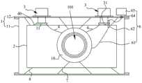
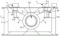
图1是本发明实施例一提供的超导磁体系统的结构示意图;Fig. 1 is a schematic structural diagram of a superconducting magnet system provided by Embodiment 1 of the present invention;
图2是本发明实施例一提供的脉动热管的示意图;Fig. 2 is a schematic diagram of a pulsating heat pipe provided by Embodiment 1 of the present invention;
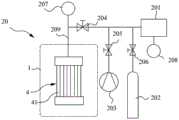
图3是本发明实施例二提供的充注系统的结构示意图;Fig. 3 is a schematic structural diagram of the filling system provided by
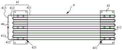
图4是本发明实施例三提供的第一热开关的结构示意图;Fig. 4 is a schematic structural diagram of a first thermal switch provided by
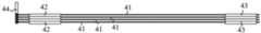
图5是图4中结构的俯视图;Fig. 5 is a top view of the structure in Fig. 4;
图6是图4中结构的侧视图;Fig. 6 is a side view of the structure in Fig. 4;
图7是本发明实施例四提供的第一热开关的结构示意图;Fig. 7 is a schematic structural diagram of a first thermal switch provided in
图8是本发明实施例五提供的第一热开关和第四热开关的结构示意图;Fig. 8 is a schematic structural diagram of the first thermal switch and the fourth thermal switch provided by Embodiment 5 of the present invention;
图9是本发明实施例六提供的超导磁体系统的结构示意图;Fig. 9 is a schematic structural diagram of a superconducting magnet system provided by Embodiment 6 of the present invention;
图10是本发明实施例七提供的超导磁体系统的结构示意图;Fig. 10 is a schematic structural diagram of a superconducting magnet system provided by Embodiment 7 of the present invention;
图11是本发明实施例八提供的超导磁体系统的结构示意图。Fig. 11 is a schematic structural diagram of a superconducting magnet system provided by
图中标记如下:The markings in the figure are as follows:
1、真空罩;11、外筒体;12、法兰盘;2、一级防辐射屏;3、制冷机;31、冷头;31a、一级冷头;31b、二级冷头;4、第一热开关;41、第一低温脉动热管;411、平行管部;412、弯折部;413、接头管部;42、冷凝板;421、第一定位槽;43、蒸发板;431、第二定位槽;44、注液接头;5、第二热开关;6、供电组件;61、超导线;62、高温超导电流引线;64、外部电流接线组件;65、超导励磁电源;7、第一支撑结构;8、第二支撑结构;9、二级防辐射屏;1. Vacuum cover; 11. Outer cylinder; 12. Flange; 2. First-level radiation shield; 3. Refrigerator; 31. Cold head; 31a, first-level cold head; 31b, second-level cold head; 4 , the first thermal switch; 41, the first low-temperature pulsating heat pipe; 411, the parallel pipe part; 412, the bending part; 413, the joint pipe part; 42, the condensation plate; 421, the first positioning groove; 43, the evaporation plate; , the second positioning groove; 44, the liquid injection joint; 5, the second thermal switch; 6, the power supply assembly; 61, the superconducting wire; 62, the high temperature superconducting current lead; 64, the external current wiring assembly; 65, the superconducting excitation power supply ; 7, the first support structure; 8, the second support structure; 9, the secondary radiation screen;
10、被冷却负载;101、室温孔;20、充注系统;201、缓冲罐;202、储气瓶;203、分子泵机组;204、第一截止阀;205、第二截止阀;206、第三截止阀;207、第一压力传感器;208、第二压力传感器;209、充注管;30、第三热开关;40、第四热开关;10. Cooled load; 101. Room temperature hole; 20. Filling system; 201. Buffer tank; 202. Gas storage bottle; 203. Molecular pump unit; 204. First stop valve; 205. Second stop valve; 206. The third cut-off valve; 207, the first pressure sensor; 208, the second pressure sensor; 209, the filling pipe; 30, the third thermal switch; 40, the fourth thermal switch;
100a、蒸发段;100b、冷凝段;100c、绝热段;100d、气塞;100e、液塞。100a, evaporation section; 100b, condensation section; 100c, adiabatic section; 100d, gas plug; 100e, liquid plug.
具体实施方式Detailed ways
下面结合附图和实施例对本发明作进一步的详细说明。可以理解的是,此处所描述的具体实施例仅仅用于解释本发明,而非对本发明的限定。另外还需要说明的是,为了便于描述,附图中仅示出了与本发明相关的部分而非全部结构。The present invention will be further described in detail below in conjunction with the accompanying drawings and embodiments. It should be understood that the specific embodiments described here are only used to explain the present invention, but not to limit the present invention. In addition, it should be noted that, for the convenience of description, only some structures related to the present invention are shown in the drawings but not all structures.
在本发明的描述中,除非另有明确的规定和限定,术语“相连”、“连接”、“固定”应做广义理解,例如,可以是固定连接,也可以是可拆卸连接,或成一体;可以是机械连接,也可以是电连接;可以是直接相连,也可以通过中间媒介间接相连,可以是两个元件内部的连通或两个元件的相互作用关系。对于本领域的普通技术人员而言,可以具体情况理解上述术语在本发明中的具体含义。In the description of the present invention, unless otherwise clearly specified and limited, the terms "connected", "connected" and "fixed" should be understood in a broad sense, for example, it can be a fixed connection, a detachable connection, or an integrated ; It can be a mechanical connection or an electrical connection; it can be a direct connection or an indirect connection through an intermediary, and it can be the internal communication of two components or the interaction relationship between two components. Those of ordinary skill in the art can understand the specific meanings of the above terms in the present invention in specific situations.
在本发明中,除非另有明确的规定和限定,第一特征在第二特征之“上”或之“下”可以包括第一和第二特征直接接触,也可以包括第一和第二特征不是直接接触而是通过它们之间的另外的特征接触。而且,第一特征在第二特征“之上”、“上方”和“上面”包括第一特征在第二特征正上方和斜上方,或仅仅表示第一特征水平高度高于第二特征。第一特征在第二特征“之下”、“下方”和“下面”包括第一特征在第二特征正下方和斜下方,或仅仅表示第一特征水平高度小于第二特征。In the present invention, unless otherwise clearly specified and limited, a first feature being "on" or "under" a second feature may include direct contact between the first and second features, and may also include the first and second features Not in direct contact but through another characteristic contact between them. Moreover, "above", "above" and "above" the first feature on the second feature include that the first feature is directly above and obliquely above the second feature, or simply means that the first feature is horizontally higher than the second feature. "Below", "beneath" and "under" the first feature to the second feature include that the first feature is directly below and obliquely below the second feature, or simply means that the first feature has a lower level than the second feature.
在本实施例的描述中,术语“上”、“下”、“右”、等方位或位置关系为基于附图所示的方位或位置关系,仅是为了便于描述和简化操作,而不是指示或暗示所指的装置或元件必须具有特定的方位、以特定的方位构造和操作,因此不能理解为对本发明的限制。此外,术语“第一”、“第二”仅仅用于在描述上加以区分,并没有特殊的含义。In the description of this embodiment, the terms "up", "down", "right", and other orientations or positional relationships are based on the orientations or positional relationships shown in the drawings, and are only for the convenience of description and simplification of operations, rather than indicating Or imply that the device or element referred to must have a specific orientation, be constructed and operate in a specific orientation, and therefore should not be construed as limiting the invention. In addition, the terms "first" and "second" are only used to distinguish in description, and have no special meaning.
实施例一Embodiment one
如图1所示,本实施例提供了一种冷却系统,其可以将被冷却负载10冷却至预设工作温度,使得被冷却负载10保持在低温环境中运行,保证被冷却负载10的运行安全性和可靠性。其中,被冷却负载10可以为超导磁体或其他比热容较大且需要在低温环境下运行的装置。As shown in Figure 1, this embodiment provides a cooling system that can cool the cooled
具体地,冷却系统包括真空罩1、制冷机3及第一热开关4。制冷机3设置有至少两个,每个制冷机3均具有冷头31,第一热开关4与制冷机31一一对应设置,被冷却负载10、冷头31及第一热开关4均位于真空罩1内。第一热开关4包括第一低温脉动热管41,第一低温脉动热管41的冷凝段与冷头31热连接,第一低温脉动热管41的蒸发段与被冷却负载10连接,当冷头31处于最终制冷温度时,第一低温脉动热管41内的第一工质处于两相流状态。Specifically, the cooling system includes a vacuum cover 1 , a
本实施例提供的冷却系统,通过使第一热开关4包括第一低温脉动热管41,当该第一热开关4对应的制冷机3正常工作时,制冷机3的冷头的温度能够达到最终制冷温度,从而使得第一低温脉动热管41的冷凝段低于饱和温度,管内的第一工质能够被冷凝成液态,而第一低温脉动热管41的蒸发段高于饱和温度,管内的第一工质由于受被冷却负载10的温度的影响而被蒸发成气态,由于毛细管径很小,在毛细力作用下,第一低温脉动热管41内的第一工质处于气液两相流状态,导热系数较高,热传递较高较好,被冷却负载10运行时产生的热量能够快速通过第一低温脉动热管41而带走;当制冷机3故障或停止工作时,由于制冷机3的冷头31的温度升高,与该制冷机3相连的冷凝段的温度升高至高于第一工质的临界温度,冷凝段内的第一工质转换为气态,第一低温脉动热管41的热阻增大,第一热开关4处于断开状态,阻止热量通过第一热开关4传递至被冷却负载10处。In the cooling system provided by this embodiment, by making the first
即,本实施例提供的冷却系统,通过设置至少两台制冷机3以及在制冷机3的冷头31和被冷却负载10之间均设置第一热开关4,能够通过制冷机3的冗余设置,保证冷却系统的运行安全性和可靠性;同时,第一低温脉动热管41在导通时,热传导比导热金属高好几个数量级,传热效率高,能够有效提高被冷却负载10的冷却效率,同时其开关比较大(能够达到2500以上),能够有效保证第一热开关4断开时的绝热性能,保证冷却系统的使用可靠性;而且,由于第一热开关4能够根据冷头31温度变化自动断开和导通,无需机械和电磁驱动,降低控制难度,提高控制精度,保证第一热开关4的使用可靠性,同时减小第一热开关4的结构复杂性和空间占用率,降低冷却系统的成本;再者,采用第一低温脉动热管41体积小、重量轻且传热距离较远,且能采用弯折布置,使得第一低温脉动热管41可以容易地集成至具有严格质量和空间限制的结构中,提高冷却系统的结构紧凑性,尤其适用于对振动比较敏感的远距离超导磁体应用中,如核磁共振成像。That is to say, the cooling system provided by this embodiment, by arranging at least two refrigerators 3 and setting the first thermal switch 4 between the cold head 31 of the refrigerator 3 and the load 10 to be cooled, can pass the redundancy of the refrigerator 3 set to ensure the safety and reliability of the cooling system; at the same time, when the first low-temperature pulsating heat pipe 41 is turned on, the heat conduction is several orders of magnitude higher than that of the heat-conducting metal, and the heat transfer efficiency is high, which can effectively improve the cooling efficiency of the cooled load 10 , while its switch is relatively large (can reach more than 2500), can effectively ensure the thermal insulation performance when the first thermal switch 4 is disconnected, and ensure the reliability of the cooling system; and, because the first thermal switch 4 can Changes are automatically disconnected and turned on, without mechanical and electromagnetic drives, reducing control difficulty, improving control accuracy, ensuring the reliability of the first thermal switch 4, and reducing the structural complexity and space occupancy of the first thermal switch 4, Reduce the cost of the cooling system; moreover, the first low-temperature pulsating heat pipe 41 is small in size, light in weight, and has a long heat transfer distance, and can be bent and arranged, so that the first low-temperature pulsating heat pipe 41 can be easily integrated into a and space-constrained structures, improving the compactness of the cooling system, especially for vibration-sensitive remote superconducting magnet applications, such as nuclear magnetic resonance imaging.
如图2所示,值得说明的是,脉动热管是一种被动传热装置,它是由一根内径较小一般为0.5~3mm的金属毛细管在热端和冷端之间反复弯折形成的蛇形管状结构,管内充满两相流体。由于管径足够小,毛细作用占主导地位,表面张力使工质在毛细管内形成随机交替分布的气塞100d和液塞100e。As shown in Figure 2, it is worth explaining that the pulsating heat pipe is a passive heat transfer device, which is formed by repeatedly bending a metal capillary tube with a small inner diameter, generally 0.5-3 mm, between the hot end and the cold end. Serpentine tubular structure filled with two-phase fluid. Since the tube diameter is small enough, the capillary action is dominant, and the surface tension causes the working fluid to form gas plugs 100d and
脉动热管通常包括冷凝段100b、蒸发段100a及位于冷凝段100b和蒸发段100a之间的绝热段100c。在脉动热管的运行过程中,对蒸发段100a施加热负荷,位于蒸发段100a的工质吸热,在液体内部或液膜表面蒸发,生成新的气泡或者使原有气泡体积增大,导致气塞100d的长度增大,蒸发段100a内的压力增大;同时对冷凝段100b施加冷负荷,在冷凝段100b的气态工质液化放热变为液态工质,使得冷凝段100b内的气泡减小或消失,冷凝段100b内的压力减小。即脉动热管的蒸发段100a和冷凝段100b之间由于温差产生推动工质由蒸发段100a流向冷凝段100b的压力差,气泡的生长和破裂导致蒸发段100a和冷凝段100b存在压差以及相邻管子之间存在压力不平衡,从而推动工质在管内脉动运动或导向循环流动,并通过气液相变的潜热和液塞100e流动时的显热传递热量。即,脉动热管内的振荡流体流动和传热完全是由局部蒸发和冷凝造成的瞬态压差驱动的,不需要机械动力输出,没有活动部件,因此具有较高的可靠性。同时,相对其他类型热管,脉动热管的气液两相通常同向流动,不存在气体阻碍液体回流的问题,且除相变传热外,工质与管壁间的强制对流传热也十分显著,具有更强的传热能力。The pulsating heat pipe generally includes a
脉动热管内的工质为高热传导率的工质,低温脉动热管为脉动热管内工质的临界温度较低的脉动热管。在本实施例中,根据待冷却负载10的预设工作温度以及一级冷头31a能达到的最终制冷温度,可以将第一工质选择为氦、氖、氢或者氮或其他能作为脉动热管工质的工质,其中氦在常压下的气液饱和温度约为4.2K,氖在常压下的气液饱和温度约为25K,氢在常压下的的气液饱和温度约为20K,氮在常压下的气液饱和温度约为77K。The working medium in the pulsating heat pipe is a working medium with high thermal conductivity, and the low-temperature pulsating heat pipe is a pulsating heat pipe with a lower critical temperature of the working medium in the pulsating heat pipe. In this embodiment, according to the preset working temperature of the load to be cooled 10 and the final cooling temperature that the primary
在本实施例中,冷凝段可以直接与冷头31连接,和/或,蒸发段直接与被冷却负载10连接,也可以将冷凝段和/或蒸发段固定于高导热的金属板上,然后将金属板与对应的冷头31或被冷却负载10连接。In this embodiment, the condensing section can be directly connected to the
可以理解的是,在本实施例中,第一低温脉动热管41的绝热段、蒸发段和/或冷凝段可以竖直布置,或者弯折布置,以适宜于第一低温脉动热管41与冷头31及被冷却负载10的连接为准,本发明对此不做具体限制。It can be understood that, in this embodiment, the adiabatic section, the evaporation section and/or the condensation section of the first low temperature pulsating
第一热开关4具有第一连接面和第二连接面,第一连接面与冷头31热连接,第二连接面与被冷却负载10连接,为提高热传导效率,第一连接面和/或第二连接面设置有导热结构,导热结构包括导热涂层和/或导热片,以增加连接处的热传导率,降低接触热阻。优选地,导热层为Apiezon N高导热脂层,导热片为铟片。The first
如图1所示,制冷机3优选为GM制冷机或脉冲管制冷机,制冷机3的制冷功率和冷头31可以达到的最终制冷温度,可以根据被冷却负载10所需的预设工作温度进行具体选型确定。制冷机3为现有成熟产品,本实施例不再对制冷机3的具体结构进行赘述。As shown in Figure 1, the
在本实施例中,真空罩1包括两端开口的外筒体11和安装于外筒体11上下两端的法兰盘12,法兰盘12与外筒体11可拆卸连接并封堵外筒体11的对应端口。该种真空罩1的结构设置,有利于真空罩1内部结构的拆装,提高冷却系统的拆装和维护便利性。在其他实施例中,外筒体11也可以仅上端开口,即法兰盘12于外筒体11的上端设置一个。In this embodiment, the vacuum cover 1 includes an outer cylinder 11 with openings at both ends and flanges 12 mounted on the upper and lower ends of the outer cylinder 11. The flange 12 is detachably connected to the outer cylinder 11 and seals the outer cylinder. The corresponding port of the body 11. The structural arrangement of the vacuum cover 1 facilitates the disassembly and assembly of the internal structure of the vacuum cover 1 and improves the convenience of disassembly and maintenance of the cooling system. In other embodiments, only the upper end of the outer cylinder 11 may be open, that is, one flange 12 is provided on the upper end of the outer cylinder 11 .
真空罩1优选采用无磁不锈钢材料制成,以避免锈蚀,且提高对其内部结构的支撑稳定性。外筒体11可以但不限定为圆筒,法兰盘12的形状与外筒体11的形状相适配。The vacuum cover 1 is preferably made of non-magnetic stainless steel to avoid corrosion and improve the support stability of its internal structure. The outer cylinder 11 can be but not limited to a cylinder, and the shape of the flange 12 is adapted to the shape of the outer cylinder 11 .
冷却系统还包括抽真空装置,抽真空装置用于对真空罩1内部空间进行抽真空。真空罩1上端的法兰盘12上开设有航空插座和真空抽气口,抽真空装置位于真空罩1外部,并通过真空抽气口对真空罩1内部进行抽真空,从而减少气体导热。The cooling system also includes a vacuum device, which is used to vacuum the inner space of the vacuum cover 1 . The flange 12 on the upper end of the vacuum cover 1 is provided with an aviation socket and a vacuum pumping port. The vacuum pumping device is located outside the vacuum cover 1, and the inside of the vacuum cover 1 is vacuumed through the vacuum pumping port, thereby reducing the heat conduction of the gas.
为进一步地提高对被冷却负载10的冷却效率,冷却系统还包括一级防辐射屏2,一级防辐射屏2悬设于真空罩1内,被冷却负载10悬设于一级防辐射屏2内部。一级防辐射屏2用于减小由真空罩1外部向被冷却负载10的热辐射,降低外部环境对被冷却负载10的干扰。In order to further improve the cooling efficiency of the cooled
一级防辐射屏2优选采用第二支撑结构8悬挂在真空罩1内,被冷却负载10通过第一支撑结构7一级防辐射屏2内。第一支撑结构7和第二支撑结构8的设置可参考现有技术,可采用高强度低热导率材料制成,如G10玻璃钢,本发明对此不做限定。一级防辐射屏2优选由无氧高纯铜制作。The primary
一级防辐射屏2优选与冷头31热连接,以使一级防辐射屏2的温度接近冷头31的温度,减少真空罩1级外部环境对冷却负载10的辐射漏热。The
优选地,冷头31通过第四热开关40与一级防辐射屏2热连接,第四热开关40包括第四低温脉动热管,第四低温脉动热管的蒸发段与一级防辐射屏2热连接,第四低温脉动热管的冷凝段与冷头31热连接,当冷头31处于最终制冷温度时,第四低温脉动热管内的第四工质处于气液两相流状态。该种设置,可以保证当某一制冷机3停机或故障时,与该制冷机3对应的第四热开关40断开,避免制冷机3上的热量传递至一级防辐射屏2上。Preferably, the
在其他一实施例中,冷头31也可以直接与一级防辐射屏2热连接,以降低成本。在其他另一实施例中,两个制冷机3可以分别为主制冷机和备用制冷机,主制冷机的冷头31直接与一级防辐射屏2热连接,备用制冷机的冷头可以通过第四热开关40与一级防辐射屏2热连接。In another embodiment, the
在本实施例中,第四低温脉动热管内的第四工质与第一低温脉动热管内的第一工质相同。In this embodiment, the fourth working fluid in the fourth low temperature pulsating heat pipe is the same as the first working fluid in the first low temperature pulsating heat pipe.
为降低辐射漏热,一级防辐射屏2外部、第一热开关4、被冷却负载10、第四热开关40和/或冷头31的外表面包裹有绝热层,绝热层优选由高真空多层绝热材料(Multi-LayerInsulation,MLI)制成。In order to reduce radiation heat leakage, the outside of the
进一步地,冷却系统还包括充注系统,充注系统用于向第一低温脉动热管41填充工质。充注系统的结构和第一低温脉动热管41的注液方式可以参考现有技术,本实施例对此不做限制。Further, the cooling system further includes a filling system, which is used to fill the first low-temperature pulsating
在本实施例中,优选地,每个第一热开关4对应设置一充注系统,以实现对每个第一热开关4中第一低温脉动热管41的单独充液控制。在其他实施例中,所有第一热开关4可以共用同一充注系统,即同一充注系统对所有第一热开关4内的第一低温脉动热管41进行同步充液。In this embodiment, preferably, each first
在一实施例中,每个第四热开关4对应设置一充注系统,一实现对每个第四热开关4中的第四低温脉动热管的单独充液控制。In an embodiment, each fourth
本实施例还提供了一种超导磁体系统,其包括超导磁体及上述的冷却系统,超导磁体即为被冷却负载10。本实施例提供的超导磁体系统,通过设置至少两个制冷机3及在制冷机3和被冷却负载10之间连接包括第一低温脉动热管41的第一热开关4,能够在制冷机3故障时,避免制冷机3的高温传递至被冷却负载10处,保证被冷却负载10能够在其他制冷机3的冷却作用下安全稳定地运行,提高超导磁体系统的运行安全性和可靠性;同时,由于第一热开关4占地空间较小,布置灵活,能够有效提高超导磁体系统的结构紧凑性,尤其适用于对振动比较敏感的远距离超导磁体应用中,如核磁共振成像。This embodiment also provides a superconducting magnet system, which includes a superconducting magnet and the above-mentioned cooling system, and the superconducting magnet is the
可以理解的是,超导磁体的预设工作温度低于超导转变温度。It can be understood that the preset operating temperature of the superconducting magnet is lower than the superconducting transition temperature.
进一步地,超导磁体包括超导磁体线圈和用于安装超导磁体线圈的支撑骨架。超导磁体通过第一支撑结构7固定在一级防辐射屏2内,第一支撑结构7可以包括拉杆或者拉环,第一支撑结构7优选采用低导热率、高绝缘性且高强度材料制成,如G10玻璃钢等。支撑骨架为筒状结构,内孔形成用于放置样品的室温孔101。当超导磁体运行时,室温孔101内有均匀磁场。Further, the superconducting magnet includes a superconducting magnet coil and a supporting frame for installing the superconducting magnet coil. The superconducting magnet is fixed in the
为了获得高磁场强度,超导磁体线圈可由多个线圈组成,线圈材料可为NbTi,Nb3Sn等常规超导材料或者二硼化镁、钇钡铜氧等高温超导材料。支撑骨架可由6063-T1铝合金等材料制成。In order to obtain high magnetic field strength, the superconducting magnet coil can be composed of multiple coils, and the coil materials can be conventional superconducting materials such as NbTi and Nb3 Sn or high-temperature superconducting materials such as magnesium diboride and yttrium barium copper oxide. The supporting frame can be made of 6063-T1 aluminum alloy and other materials.
室温孔101的中心轴线可以沿竖直方向或水平方向设置,也可以沿其他方向布置,即室温孔101的中心轴线可以根据超导磁体系统的具体类型以及应用场景进行具体设置。The central axis of the
在本实施例中,第一热开关4的蒸发段与支撑骨架连接,以提高第一热开关4与超导磁体的连接便利性。In this embodiment, the evaporating section of the first
超导磁体系统还包括二级管组件,二级管组件用于超导磁体的失超保护。超导磁体系统还包括供电组件6,供电组件6包括超导励磁电源65以及连接在超导励磁电源65和超导磁体线圈之间的导线61。超导励磁电源65位于真空罩1外部。The superconducting magnet system also includes a diode assembly, which is used for quench protection of the superconducting magnet. The superconducting magnet system also includes a power supply assembly 6, which includes a superconducting excitation power supply 65 and
为更好地实现超导磁体与超导励磁电源65之间的连接,超导磁体系统还外部电流接线组件64和高温超导电流引线62,高温超导电流引线62与冷头31热连接,外部电流接线组件64和高温超导电流引线62之间以及高温超导电流引线62与被冷却负载10之间均连接有导线61,外部电流接线组件64安装于真空罩1上,以对接位于真空罩1内外两侧的导线61。外部电流接线组件64与真空罩1绝缘设置。高温超导电流引线62与外部电流接线组64的具体结构可参考现有技术,本发明对此不做赘述和限定。In order to better realize the connection between the superconducting magnet and the superconducting excitation power supply 65, the superconducting magnet system also has an external
本实施例提供的超导磁体系统可应用于信息技术、生物医学、环境技术、军工、工业加工、海洋、交通运输、大科学工程及超导电力方面,如医用核磁共振成像设备MRI、核磁共振谱仪MNR、超导磁分离系统、超导储能系统、超导电机、超导电缆、超导变压器、超导限流器、超导感应加热、超导粒子加速器、超导磁悬浮列车等等,本发明对超导磁体系统的具体类型和应用场景不做限制。The superconducting magnet system provided in this embodiment can be applied to information technology, biomedicine, environmental technology, military industry, industrial processing, marine, transportation, large scientific engineering and superconducting power, such as medical nuclear magnetic resonance imaging equipment MRI, nuclear magnetic resonance Spectrometer MNR, superconducting magnetic separation system, superconducting energy storage system, superconducting motor, superconducting cable, superconducting transformer, superconducting current limiter, superconducting induction heating, superconducting particle accelerator, superconducting maglev train, etc. , the present invention does not limit the specific type and application scenarios of the superconducting magnet system.
实施例二Embodiment two
本实施例提供了一种冷却系统和超导磁体系统,且本实施例提供的冷却系统和超导磁体系统是基于实施例一中结构的进一步改进,本实施例不再对与实施例一相同的结构进行赘述。This embodiment provides a cooling system and a superconducting magnet system, and the cooling system and the superconducting magnet system provided in this embodiment are further improvements based on the structure in Embodiment 1, and this embodiment is no longer the same as Embodiment 1 structure is described.
在本实施例中,冷却系统还包括充注系统20,充注系统20用于向第一热开关4的第一低温脉动热管41内充注第一工质,充注系统20主要位于真空罩1外部。In this embodiment, the cooling system further includes a charging
具体地,充注系统20包括缓冲罐201、储气瓶202及分子泵机组203及充注管209,缓冲罐201通过第一管路与充注管209的进气端连接,分子泵机组203通过第二管路与充注管209的进气端连接,充注管209的出气端与第一热开关4连接,储气瓶202通过第三管路与充注管209的进气端连接。其中,充注管209上设置有第一截止阀204,第二管路上设置有第二截止阀205,第三管路上设置有第三截止阀206。Specifically, the charging
充注系统20还包括第一压力传感器207,其设置在充注管209上,用于检测第一低温脉动热管41的冷凝段的压力波动。缓冲罐201处设置有第二压力传感器208,其用于检测缓冲罐201的压力并计算充液率。The charging
储气瓶202内存储有高纯度(纯度99.999%)且气态的第一工质,第一低温脉动热管41的充液过程具体的操作步骤如下:The
(1)采集并记录温度、压力数据。(1) Collect and record temperature and pressure data.
(2)使用高纯第一工质和一组分子泵机组203对第一低温脉动热管41、缓冲罐201和充注系统20内的管道进行气体的吹扫和净化,以防止管道中残余的空气或其他杂质影响实验。(2) Use the first high-purity working fluid and a group of
具体过程是:The specific process is:
首先开启第一截止阀204和第二截止阀205,关闭第三截止阀206,使用分子泵机组203将第一低温脉动热管41和充注系统20抽至高真空(<1×10⁻³Pa);First open the first cut-off
然后关闭第二截止阀205,开启第一截止阀204和第三截止阀206,将99.999%的高纯第一工质从储气瓶202充入第一低温脉动热管41和缓冲罐201中;Then close the second shut-off
同样的过程重复5次以上,以彻底清除脉动热管和充注系统20内的杂质气体,完成后抽至高真空。The same process is repeated more than 5 times to completely remove the impurity gas in the pulsating heat pipe and the charging
(3)纯化过程完成后,开启第三截止阀206,关闭第一截止阀204和第二截止阀205,开启储气瓶202,向缓冲罐201充入高纯第一工质,然后关闭第一截止阀204,记录此时缓冲罐201的初始压力P0。(3) After the purification process is completed, open the third shut-off
(4)开启第一截止阀204,关闭第二截止阀205和第三截止阀206,高纯第一工质将从缓冲罐201进入第一低温脉动热管41。(4) Open the
(5)使用另一组分子泵机组203对真空罩1内进行抽真空,待真空罩1内的真空度小于1×10⁻³Pa后,启动制冷机3对第一低温脉动热管41进行降温冷却。(5) Use another group of
(6)随着第一低温脉动热管41冷凝段的温度降低,压力也下降,当降至第一工质的气液两相流温区时,液态的第一工质开始生成,压力迅速下降,液态第一工质在重力作用下从冷凝段移动至蒸发段并吸热蒸发,加快蒸发段冷却至工作温度。当缓冲罐201的压力降至目标充液率对应的压力P1时,关闭第一截止阀204,第一低温脉动热管41与充注系统20隔离。此时,第一低温脉动热管41管内为气塞和液塞交替分布的初始状态,充液过程结束。(6) As the temperature of the condensing section of the first low-temperature pulsating
用充液率来表示第一低温脉动热管41中充入液态第一工质的质量,为与现有研究数据进行比较,当第一工质为氦时,充液率定义为4.215K下液氦容积与脉动热管容积的比值。The liquid filling rate is used to represent the mass of the liquid first working fluid in the first low-temperature pulsating
计算充液率时,第一低温脉动热管41和充注系统20内的第一工质视为理想气体,根据质量守恒定律和理想气体状态方程,充入第一工质的质量mt可由下式计算:When calculating the liquid filling rate, the first low-temperature pulsating

其中:P0和P1分别为充液过程开始和结束时缓冲罐201的初始压力和最终压力,单位为Pa;VFT和VBT分别为充液管(第一截止阀204至第一低温脉动热管41的部分)和缓冲罐201的体积,单位为m3;TFT和TBT分别为充液管路和缓冲罐201的平均温度,单位为K;Rg为第一工质的气体常数,如当第一工质为氦时,Rg=2077J/(kg·K);mt为充入脉动热管的工质的质量,单位为kg。Wherein: P0 and P1 are the initial pressure and the final pressure of the
充入第一低温脉动热管41的液态工质的质量为第一工质的饱和气体质量和饱和液体质量的总和。以第一工质为氦为例,充入第一低温脉动热管41的液氦的质量为饱和氦气质量和饱和液氦质量的总和。由于饱和氦气以及饱和液氦的密度及充入第一低温脉动热管41的氦的质量是已知的,因此饱和液氦的体积可由下式求得:The mass of the liquid working medium charged into the first low-temperature pulsating
mt=ρlVl+ρv(VPHP-Vl)(式2);mt =ρl Vl +ρv (VPHP -Vl ) (Formula 2);
其中,VPHP和Vl分别为第一低温脉动热管41的体积和管内液氦的体积,单位为m3;ρv和ρl分别为饱和氦气和饱和液氦在4.215K时的密度,单位为kg/m3。Wherein, VPHP and Vl are respectively the volume of the first low-temperature pulsating
因此,充液率为:Therefore, the filling rate is:

联立式1~式3,根据缓冲罐201的初始压力和最终压力,即可确定第一低温脉动热管41的充液率。该充液率的计算公式考虑了充液管体积的影响,同时充注系统20其余部分管道的体积被考虑为缓冲罐201的体积的一部分。The simultaneous equations 1 to 3 can determine the liquid filling rate of the first low-temperature pulsating
需要说明的是,本充液方法也适用于其他低温工质。It should be noted that this filling method is also applicable to other cryogenic working fluids.
第一低温脉动热管41的充液率建议在20%~80%之间,充液率太低容易烧干,充液率太高流动阻力大,难以启动运行。The liquid filling rate of the first low-temperature pulsating
缓冲罐201的作用除了在第一低温脉动热管41运行前控制充液率以外,也可以在第一低温脉动热管41运行时自动调节充液率和压力,防止烧干。只需要把第一截止阀204打开,让缓冲罐201连接第一低温脉动热管41运行即可。The function of the
值得说明的是,当第四热开关40对应的充注系统与第一热开关4对应的充注系统分别设置时,第四热开关40的充注系统可以参考第一热开关4的充注系统进行设置。It is worth noting that when the charging system corresponding to the fourth
实施例三Embodiment Three
本实施例提供了一种冷却系统和低温超导磁系统,且本实施例提供的冷却系统是对实施例一中的冷却系统进行的进一步改进,本实施例不再对与实施例一相同的内容进行赘述。This embodiment provides a cooling system and a low-temperature superconducting magnetic system, and the cooling system provided by this embodiment is a further improvement on the cooling system in Embodiment 1. This embodiment no longer uses the same components as Embodiment 1 The content will be repeated.
如图4-图6所示,在本实施例中,第一热开关4还包括冷凝板42、蒸发板43和注液接头44。第一低温脉动热管41为由毛细管弯折形成蛇形结构,其包括在第一方向上平行且间隔设置的多个平行管部411和连接于相邻两个平行管部411之间的弯折部412。平行管部411具有依次连接的冷凝段、绝热段和蒸发段。As shown in FIGS. 4-6 , in this embodiment, the first
冷凝板42上开设有多个第一定位槽421,蒸发板43的表面开设有多个第二定位槽431,第一定位槽421第二定位槽431均与平行管部411一一对应设置,平行管部411的冷凝段位于第一定位槽421中,平行管部411的蒸发段位于第二定位槽431中,且第一定位槽421和第二定位槽431内均填充有焊锡,以固定第一低温脉动热管41与对应的冷凝板42及蒸发板43,且减小热阻,保证第一低温脉动热管41与冷凝板42及蒸发板43之间的良好热接触。连接于冷凝段的弯折部412位于冷凝板42远离蒸发板43的一侧,且连接于蒸发段的弯折部412蒸发板43远离冷凝板42的一侧。The
第一定位槽421和第二定位槽431的槽宽优选大于第一低温脉动热管41的外径,以保证第一低温脉动热管41容置在第一定位槽421和第二定位槽431中,且为焊锡的填充提供空间。蒸发板43和冷凝板42均优选采用纯铜制成,热传导效率较高。第一低温脉动热管41优选采用不锈钢或者纯铜制成。The groove width of the
第一热开关4优选为多层结构,即平行管部411沿第二方向延伸,第一热开关4优选包括沿第三方向并排设置的多层第一低温脉动热管41,蒸发板43及冷凝板42均与第一低温脉动热管41一一对应设置,第一方向、第二方向及第三方向两两相互垂直。具有多层第一低温脉动热管41的第一热开关4,能够增大热传导率的同时,节省第一热开关4的占地空间,提高第一热开关4的结构紧凑性。The first
在本实施例中,所有蒸发板43在第三方向上层叠设置并紧固连接,所有冷凝板42在第三方向上层叠设置并紧固连接。In this embodiment, all the evaporating
注液接头44内设置有注液通道,充注系统的充注管通过注液通道与第一低温脉动热管41连通。在本实施例中,所有第一低温脉动热管41并联设置,每个第一低温脉动热管41的两端均形成有接头管部413,注液通道与第一低温脉动热管41一一对应设置,每个第一低温脉动热管41的两个接头管部413均插入注液通道中并与注液通道密封连通。该种设置,能够简化第一热开关4的加工,提高第一热开关4拆装便利性。A liquid injection channel is provided in the liquid injection joint 44 , and the filling pipe of the filling system communicates with the first low-temperature pulsating
在其他实施例中,所有第一低温脉动热管41串联设置,即相邻两个第一低温脉动热管41的对应端连接,所有第一低温脉动热管41仅具有两个接头管部413,注液接头44设置有一个注液通道,两个接头管部413插入注液通道内并与注液通道密封连通。In other embodiments, all the first low-temperature pulsating
示例性地,第一低温脉动热管41设置有四层,每层第一低温脉动热管41具有12个平行管部411。在其他实施例中,第一低温脉动热管41的层数以及第一低温脉动热管41包含的平行管部411的数量可以根据需求进行设置,如可以为三层、五层或者更多层,每层包括6~18个平行管部411。Exemplarily, the first low temperature pulsating
进一步地,在第一热开关4的加工过程中,相邻两层之间的蒸发板43以及相邻两层的冷凝板42均先用焊锡焊接,使空隙尽量被焊锡填满;再用螺栓或螺钉锁附所有蒸发板43及锁附所有冷凝板42。Further, during the processing of the first
在其他另一实施例中,第一热开关4也可以包括在第一方向并排设置的多个第一低温脉动热管41,每个第一低温脉动热管41均单独设置一注液接头44和充注系统,即每个第一低温脉动热管41可以单独被控制注液。在其他又一实施例中,第一热开关4可以包括多个在第一方向上并排设置的多个第一低温脉动热管41,每个第一低温脉动热管41的两端均接入一连通管中,连通管与充注系统连通。In another other embodiment, the first
第一热开关4具有第一连接面和第二连接面,第一连接面与冷头31热连接,第二连接面与被冷却负载10热连接。在本实施例中,最外侧一层的蒸发板43远离相邻蒸发板43的一侧具有第二连接面,最外层的冷凝板42远离相邻冷凝板42的一侧具有第一连接面。The first
为提高热传导效率,第一连接面和/或第二连接面设置有导热结构,导热结构包括导热涂层和/或导热片,以增加连接处的热传导率,降低接触热阻。优选地,导热层为Apiezon N高导热脂层,导热片为铟片。In order to improve the heat conduction efficiency, the first connection surface and/or the second connection surface are provided with a heat conduction structure, and the heat conduction structure includes a heat conduction coating and/or a heat conduction sheet, so as to increase the heat conduction rate of the connection and reduce the contact thermal resistance. Preferably, the heat conduction layer is an Apiezon N high heat conduction grease layer, and the heat conduction sheet is an indium sheet.
值得说明的是,第四热开关40的结构可以参照上述第一热开关4的结构进行设置,此次不再赘述。It is worth noting that the structure of the fourth
实施例四Embodiment four
如图7所示,本实施例提供了一种冷却系统和超导磁体系统,本实施例提供的冷却系统和超导磁体系统与实施例三基本相同,仅部分设置存在差异,本实施例不再对与实施例三相同的结构进行赘述。As shown in Figure 7, this embodiment provides a cooling system and a superconducting magnet system. The cooling system and the superconducting magnet system provided in this embodiment are basically the same as those in
在本实施例中,多个蒸发板43分为分离设置的至少两组,每组蒸发板43包括一个蒸发板43或层叠设置的至少两个蒸发板43,相邻两组蒸发板43在第一方向上间隔设置,每组蒸发板43中均有第二连接面。In this embodiment, a plurality of evaporating
通过设置至少两组蒸发板43,可以增加第一热开关4与被冷却负载10的接触位置,从而提高被冷却负载10各处的冷却均匀性,进一步提高冷却效率。By arranging at least two sets of evaporating
在本实施例中,第一热开关4与第四热开关40分体设置,第一热开关4具有两组蒸发板43,两组蒸发板43的两个第二连接面分别连接被冷却负载10的上下两端,以在提高被冷却负载10的冷却均匀性的同时,降低成本。In this embodiment, the first
实施例五Embodiment five
如图8所示,本实施例提供了一种冷却系统和超导磁体系统,本实施例提供的冷却系统和超导磁体系统与实施例三基本相同,仅部分设置存在差异,本实施例不在对与实施例三相同的结构进行赘述。As shown in Figure 8, this embodiment provides a cooling system and a superconducting magnet system. The cooling system and the superconducting magnet system provided in this embodiment are basically the same as those in
在本实施例中,第一热开关4和第四热开关40集成设置,第一热开关4和第四热开关40对应的蒸发板4错位设置,第一热开关4和第四热开关40对应的冷凝板层叠设置,且第一热开关4和第四热开关40共用一个注液接头。该种设置,能够减小第一热开关4和第四热开关40的占地空间,提高结构紧凑性,且可以实现对第一热开关4和第四热开关40的同时注液。In this embodiment, the first
可以理解的是,在本实施例中,第一热开关4也可以设置两组或两组以上蒸发板42,每组蒸发板42均与被冷却负载10连接,以提高被冷却负载10的冷却均匀性。第四热开关40也可以设置两组或两组以上的蒸发板,每组蒸发板均与一级防辐射屏2热连接,以提高一级防辐射屏2被冷却的均匀性。It can be understood that, in this embodiment, the first
实施例六Embodiment six
如图9所示,本实施例提供了一种冷却系统及超导磁体系统,且本实施例提供的冷却系统及超导磁体系统基本结构与实施例一相同,仅部分设置存在差异,本实施例不再对与实施例一相同的内容进行赘述。As shown in Figure 9, this embodiment provides a cooling system and a superconducting magnet system, and the basic structure of the cooling system and the superconducting magnet system provided by this embodiment is the same as that of Embodiment 1, only some settings are different. Example The content that is the same as that in the first embodiment will not be repeated.
在本实施例中,制冷机3具有两个冷头31,两个冷头31分别为一级冷头31a和二级冷头31b,在制冷机3正常运行时,一级冷头31a的最终制冷温度高于二级冷头31b的最终制冷温度,第一热开关4与二级冷头31b热连接。In this embodiment, the
制冷系统还包括第二热开关5,第二热开关5包括第二低温脉动热管,第二低温脉动热管的蒸发段与被冷却负载10连接,第二低温脉动热管的冷凝段与一级冷头31a连接,第二低温脉动热管内的第二工质的三相点临界高于一级冷头31a的最终制冷温度。The refrigeration system also includes a second thermal switch 5, the second thermal switch 5 includes a second low-temperature pulsating heat pipe, the evaporation section of the second low-temperature pulsating heat pipe is connected to the cooled
本实施例提供的冷却系统,由于第二低温脉动热管的临界温度高于一级冷头31a的最终制冷温度,而一级冷头31a的最终制冷温度高于二级冷头31b的最终最冷温度,因此在制冷机3未工作时,第一低温脉动热管41内的工质处于气态,此时第二热开关5的热阻较大,第二热开关5处于断开状态;在冷却系统冷却过程中,一级冷头31a的温度先下降至第二低温脉动热管的临界温度,第二低温脉动热管的冷凝段的第二工质被冷凝成液态,第二低温脉动热管处于气液两相流状态,导热系数较高,传递效果较高,使得第二热开关处于导通状态,将一级冷头31a的冷量传递至被冷却负载10,加速被冷却负载10降温,缩短被冷却负载10冷却至预设工作温度所需时间,从而提高冷却系统的运行效率;当被冷却负载10冷却至第二工质的三相点温度后,第二低温脉动热管的冷凝段的温度随一级冷头31a降低至第二工质的三相点温度以下,第二低温脉动热管内的第二工质转变成固态,流动停止,热阻增大,第二热开关5处于断开状态,被冷却负载10主要通过第一热开关4进行热传导,被冷却负载10的温度随二级冷头31b的温度的降低而降低,最终被冷却负载10被冷却至预设工作温度。In the cooling system provided by this embodiment, since the critical temperature of the second low-temperature pulsating heat pipe is higher than the final cooling temperature of the primary
同时,在被冷却负载10运行过程中,若被冷却负载10温度上升至第二低温脉动热管的三相点温度,则第二低温脉动热管的蒸发段内的第二工质融化成液态,通过控制一级冷头31a的温度,可以使第二低温脉动热管内的第二工质处于气液两相流状态,即第二热开关5导通,将被冷却负载10的热量通过热开关5快速传递至一级冷头31a处,实现热量由第一热开关5至一级冷头31a的热传导,提高传热效率,避免被冷却负载10温升较大,有效促进被冷却负载10由温升状态回复至正常工作状态,缩短被冷却负载10回复至正常工作状态的时间。At the same time, during the operation of the cooled
即,本实施例提供的冷却系统,能够在实现制冷机3的冗余设计的同时,也能够增加对制冷机3的冷量利用,提高被冷却负载10的冷却效率,降低冷却所需时长,且能够有效提高冷却系统和超导磁体系统的运行可靠性。That is to say, the cooling system provided by this embodiment can increase the utilization of cooling capacity of the
第二低温脉动热管内填充的第二工质优选为氮,其成本较低。第二低温脉动热管的工质可以为为氩、氪、氧、氨、甲烷等,第一低温脉动热管的工质也可以为氦、氢、氖等。第一低温脉动热管内的第一工质和第二低温脉动热管内的第二工质可以根据被冷却负载10所需预设工作温度进行具体选择。The second working fluid filled in the second low-temperature pulsating heat pipe is preferably nitrogen, and its cost is relatively low. The working fluid of the second low temperature pulsating heat pipe may be argon, krypton, oxygen, ammonia, methane, etc., and the working fluid of the first low temperature pulsating heat pipe may also be helium, hydrogen, neon, etc. The first working fluid in the first low-temperature pulsating heat pipe and the second working fluid in the second low-temperature pulsating heat pipe can be specifically selected according to the preset working temperature required by the
第二热开关5结构可以参照实施例一、实施例三或实施例四中的第一热开关4的结构进行设置,本实施例不再赘述。且本实施例的第一热开关4的结构也可以采用实施例三和实施例四中的热开关的结构,此处不再赘述。The structure of the second thermal switch 5 can be set with reference to the structure of the first
在本实施例中,第二低温脉动热管对应的充注系统和充液方法可以参考实施例二中的设置,本实施例对此次不做赘述。In this embodiment, the filling system and liquid filling method corresponding to the second low-temperature pulsating heat pipe can refer to the settings in the second embodiment, and this embodiment will not repeat it this time.
优选地,在本实施例中,一级冷头31a与一级防辐射屏2热连接,以吸收环境至一级防辐射屏2的热辐射。Preferably, in this embodiment, the primary
与实施例一不同之处在于,在本实施例中,一级冷头31a通过第四热开关5与一级防辐射屏2连接,第四热开关40包括第四低温脉动热管,第四低温脉动热管的蒸发段与一级防辐射屏2热连接,第四低温脉动热管的冷凝段与一级冷头31a热连接,当一级冷头31a处于最终制冷温度时,第四低温脉动热管内的第四工质处于气液两相流状态。该种设置,可以保证当某一制冷机3停机或故障时,与该制冷机3对应的第四热开关40断开,避免制冷机3上的热量传递至一级防辐射屏2上。The difference from Embodiment 1 is that in this embodiment, the primary
即,在本实施例中,第四工质与第一工质不同,第四工质的三相点温度高于第一工质的三相点温度且低于第二工质的三相点温度。第四工质的类型可以根据一级冷头31a的最终制冷温度进行确定。That is, in this embodiment, the fourth working fluid is different from the first working fluid, and the triple point temperature of the fourth working fluid is higher than that of the first working fluid and lower than that of the second working fluid. temperature. The type of the fourth working medium can be determined according to the final refrigeration temperature of the primary
需要指出的是,在超导磁体外侧、一级防辐射屏2外侧、第一热开关4外表面、第二热开关5的外表面、第四热开关40的外表面、一级冷头31a和/或二级冷头31b外侧包裹有绝热层,绝热层优选采用MLI材料,以提高绝热效果,减少辐射漏热。绝热层优选具有至少20层,以提高绝热效果。It should be pointed out that, on the outer side of the superconducting magnet, the outer side of the
进一步地,每个第一热开关4、每个第二热开关5及每个第四热开关40分别对应设置一充注系统,以实现对每个热开关的单独充液控制。Further, each first
实施例七Embodiment seven
如图10所示,本实施例提供了一种冷却系统及超导磁体系统,且本实施例提供的冷却系统与实施例五中的冷却系统基本相同,仅部分结构存在差异,本实施例不再对与实施例六相同的内容进行赘述。As shown in Figure 10, this embodiment provides a cooling system and a superconducting magnet system, and the cooling system provided by this embodiment is basically the same as the cooling system in Embodiment 5, only some structures are different, and this embodiment does not The same content as the sixth embodiment will be described again.
在本实施例中,一级冷头31a通过第四热开关40与一级防辐射屏2热连接,二级冷头31b通过第一热开关4与被冷却负载10热连接。In this embodiment, the primary
即,本实施例提供的一级冷头31a不与被冷却负载10连接,或通过其他低温热开关与被冷却负载10连接,而第四热开关40与一级防辐射屏2连接,使得制冷机3在运行时,一级冷头31a能够吸收一级防辐射屏2处的热量,降低热辐射对于被冷却负载10的影响。当制冷机3停止运行或故障时,与该制冷机3对应的一级冷头31a和二级冷头31b均温度升高,第一热开关4和第四热开关均处于断开状态。That is, the primary
实施例八Embodiment eight
如图11所示,本实施例提供了一种冷却系统及超导磁体系统,本实施例提供的超导磁系统的冷却系统是对于上述任一实施例中的冷却系统的进一步改进,本实施例不再对与上述实施例相同的结构进行赘述。As shown in Figure 11, this embodiment provides a cooling system and a superconducting magnet system. The cooling system of the superconducting magnetic system provided by this embodiment is a further improvement on the cooling system in any of the above-mentioned embodiments. This embodiment The same structure as the above embodiment will not be described again.
在本实施例中,一级防辐射屏2内部悬设有二级防辐射屏9,被冷却负载10位于二级防辐射屏9内部。即通过在一级防辐射屏2的内部设置二级防辐射屏9,将被冷却负载10设置在二级防辐射屏9内,能够更好地限制真空罩1处的热量辐射至被冷却负载10处。In this embodiment, the secondary
一级冷头31a与一级防辐射屏2热连接,以吸收一级防辐射屏2的辐射漏热;二级冷头31b与二级防辐射屏9热连接,以吸收二级防辐射屏9的辐射漏热,且使得二级防辐射屏9保持至与被冷却负载10相同的温度,利于更好地维持被冷却负载10的工作环境温度。The primary
优选地,在本实施例中,二级防辐射屏9通过第三热开关30与二级冷头31b连接,第三热开关30包括第三低温脉动热管,第三低温脉动热管的蒸发段与二级防辐射屏9热连接,第三低温脉动热管的冷凝段与二级冷头31b热连接,当二级冷头31b处于最终制冷温度时,第三低温脉动热管内的第三工质处于气液两相流状态。Preferably, in this embodiment, the
上述设置,使得当一制冷机4停机或故障时,与该制冷机4对应的一级热开关4及第三热开关30均断开,避免制冷机4上的热量传递至二级防辐射屏9处而影响二级防辐射屏4的温度控制,提高制冷效果。The above arrangement makes when a
在其他一实施例中,二级冷头31b也可以直接与二级防辐射屏9热连接,以降低成本。在其他另一实施例中,两个制冷机3可以分别为主制冷机和备用制冷机,主制冷机的二级冷头31b直接与二级防辐射屏9热连接,备用制冷机的二级冷头31b可以通过第三热开关30与二级防辐射屏9热连接。In another embodiment, the secondary
在本实施例中,第三低温脉动热管内的第三工质与第一低温脉动热管内的第一工质相同。第二低温脉动热管内第二工质的三相点温度高于第四低温脉动热管内的三相点温度,第四低温脉动热管内的三相点温度高于第一工质的三点点温度。In this embodiment, the third working fluid in the third low temperature pulsating heat pipe is the same as the first working fluid in the first low temperature pulsating heat pipe. The triple point temperature of the second working fluid in the second low temperature pulsating heat pipe is higher than the triple point temperature in the fourth low temperature pulsating heat pipe, and the triple point temperature in the fourth low temperature pulsating heat pipe is higher than the triple point temperature of the first working fluid .
在本实施例中,第二热开关5和第三热开关30的设置,可以参照实施例二至实施例五中任一实施例中的设置,即第二热开关5和第三热开关30可以分开设置,也可以集成设置,本实施例不再赘述。In this embodiment, the setting of the second thermal switch 5 and the third
优选地,一级防辐射屏2及二级防辐射屏9的外部均包覆有绝热层,绝热层优选采用高真空多层绝热材料,以进一步减少辐射漏热。Preferably, the exteriors of the primary
进一步地,一级冷头31a、二级冷头31b、第一热开关4、第二热开关5、第三热开关30和/或第四热开关40外部均包裹有绝热层,绝热层优选采用高真空多层绝热材料。Further, the primary
注意,上述仅为本发明的较佳实施例及所运用技术原理。本领域技术人员会理解,本发明不限于这里所述的特定实施例,对本领域技术人员来说能够进行各种明显的变化、重新调整和替代而不会脱离本发明的保护范围。因此,虽然通过以上实施例对本发明进行了较为详细的说明,但是本发明不仅仅限于以上实施例,在不脱离本发明构思的情况下,还可以包括更多其他等效实施例,而本发明的范围由所附的权利要求范围决定。Note that the above are only preferred embodiments of the present invention and applied technical principles. Those skilled in the art will understand that the present invention is not limited to the specific embodiments described herein, and that various obvious changes, rearrangements and substitutions can be made by those skilled in the art without departing from the protection scope of the present invention. Therefore, although the present invention has been described in detail through the above embodiments, the present invention is not limited to the above embodiments, and can also include more other equivalent embodiments without departing from the concept of the present invention, and the present invention The scope is determined by the scope of the appended claims.
Claims (10)
Translated fromChinesePriority Applications (1)
| Application Number | Priority Date | Filing Date | Title |
|---|---|---|---|
| CN202310343344.1ACN116206847A (en) | 2023-04-03 | 2023-04-03 | A cooling system and a superconducting magnet system |
Applications Claiming Priority (1)
| Application Number | Priority Date | Filing Date | Title |
|---|---|---|---|
| CN202310343344.1ACN116206847A (en) | 2023-04-03 | 2023-04-03 | A cooling system and a superconducting magnet system |
Publications (1)
| Publication Number | Publication Date |
|---|---|
| CN116206847Atrue CN116206847A (en) | 2023-06-02 |
Family
ID=86511369
Family Applications (1)
| Application Number | Title | Priority Date | Filing Date |
|---|---|---|---|
| CN202310343344.1APendingCN116206847A (en) | 2023-04-03 | 2023-04-03 | A cooling system and a superconducting magnet system |
Country Status (1)
| Country | Link |
|---|---|
| CN (1) | CN116206847A (en) |
Cited By (1)
| Publication number | Priority date | Publication date | Assignee | Title |
|---|---|---|---|---|
| CN117739612A (en)* | 2023-07-12 | 2024-03-22 | 西湖大学 | Liquid helium consumption free circulating refrigerating system and liquid helium temperature zone electron microscope |
Citations (4)
| Publication number | Priority date | Publication date | Assignee | Title |
|---|---|---|---|---|
| CN101144657A (en)* | 2007-09-30 | 2008-03-19 | 中国科学院合肥物质科学研究院 | Method and device for producing liquid helium with G-M refrigerator |
| WO2013085181A1 (en)* | 2011-12-06 | 2013-06-13 | Korea Basic Science Institute | Cooling system for superconductive magnets |
| CN103377788A (en)* | 2012-04-27 | 2013-10-30 | 中国科学院高能物理研究所 | Superconducting magnet system |
| CN113035486A (en)* | 2019-12-09 | 2021-06-25 | 中国航天科工飞航技术研究院(中国航天海鹰机电技术研究院) | Refrigerating system of low-temperature superconducting magnet |
- 2023
- 2023-04-03CNCN202310343344.1Apatent/CN116206847A/enactivePending
Patent Citations (4)
| Publication number | Priority date | Publication date | Assignee | Title |
|---|---|---|---|---|
| CN101144657A (en)* | 2007-09-30 | 2008-03-19 | 中国科学院合肥物质科学研究院 | Method and device for producing liquid helium with G-M refrigerator |
| WO2013085181A1 (en)* | 2011-12-06 | 2013-06-13 | Korea Basic Science Institute | Cooling system for superconductive magnets |
| CN103377788A (en)* | 2012-04-27 | 2013-10-30 | 中国科学院高能物理研究所 | Superconducting magnet system |
| CN113035486A (en)* | 2019-12-09 | 2021-06-25 | 中国航天科工飞航技术研究院(中国航天海鹰机电技术研究院) | Refrigerating system of low-temperature superconducting magnet |
Cited By (1)
| Publication number | Priority date | Publication date | Assignee | Title |
|---|---|---|---|---|
| CN117739612A (en)* | 2023-07-12 | 2024-03-22 | 西湖大学 | Liquid helium consumption free circulating refrigerating system and liquid helium temperature zone electron microscope |
Similar Documents
| Publication | Publication Date | Title |
|---|---|---|
| Mito et al. | Achievement of high heat removal characteristics of superconducting magnets with imbedded oscillating heat pipes | |
| CN116344150A (en) | A kind of cooling system, superconducting magnet system and cooling method | |
| US20180315530A1 (en) | Method and apparatus for cooling a superconducting device immersed in liquid nitrogen | |
| CN101030469A (en) | superconducting magnet device | |
| CN107068329A (en) | A kind of extension type magnetizes current lead device and its application method | |
| CN1653676A (en) | Superconducting device with a cooling head of a refrigeration unit thermally connected to a rotating superconducting winding | |
| CN107003373A (en) | System and method for cooling down MR imaging apparatus | |
| Gong et al. | The cryogenic system for the Panda-X dark matter search experiment | |
| CN109525069B (en) | High-temperature superconducting motor rotor cryogenic cooling system | |
| CN116206847A (en) | A cooling system and a superconducting magnet system | |
| CN114111156A (en) | Modular low-temperature refrigeration system device and building method | |
| US6640552B1 (en) | Cryogenic superconductor cooling system | |
| Giboni et al. | A LN2-based cooling system for a next-generation liquid xenon dark matter detector | |
| US5979176A (en) | Refrigerator | |
| Niinikoski | Dilution refrigerator for a two-litre polarized target | |
| CN112271052A (en) | Superconducting magnet cryogenic system | |
| CN117410056A (en) | A 2K liquid helium zero-evaporation superconducting magnet low-temperature system | |
| CN216897891U (en) | DC-coupled regenerative chiller-cooled cryogenic storage system | |
| CN213070771U (en) | Superconducting magnet cryogenic system | |
| JP7348410B1 (en) | Superconducting magnet system for cyclotron and cyclotron with it | |
| RU2601218C1 (en) | Method of inductive accumulator superconducting winding cryostatting and supply and device for its implementation | |
| Hakuraku et al. | Thermal design and tests of a subcooled superfluid helium refrigerator | |
| Taylor et al. | An efficient cooling loop for connecting cryocooler to a helium reservoir | |
| CN103262373A (en) | Current lead device | |
| Mizumaki et al. | Development of the magnetically floating superconducting dipole in the RT-1 plasma device |
Legal Events
| Date | Code | Title | Description |
|---|---|---|---|
| PB01 | Publication | ||
| PB01 | Publication | ||
| SE01 | Entry into force of request for substantive examination | ||
| SE01 | Entry into force of request for substantive examination |