CN116191362A - Control method of power converter and LLC controller - Google Patents
Control method of power converter and LLC controllerDownload PDFInfo
- Publication number
- CN116191362A CN116191362ACN202111419334.9ACN202111419334ACN116191362ACN 116191362 ACN116191362 ACN 116191362ACN 202111419334 ACN202111419334 ACN 202111419334ACN 116191362 ACN116191362 ACN 116191362A
- Authority
- CN
- China
- Prior art keywords
- duty cycle
- arm switch
- upper arm
- resonant circuit
- lower arm
- Prior art date
- Legal status (The legal status is an assumption and is not a legal conclusion. Google has not performed a legal analysis and makes no representation as to the accuracy of the status listed.)
- Pending
Links
- 238000000034methodMethods0.000titleclaimsabstractdescription17
- 238000001514detection methodMethods0.000claimsabstractdescription42
- 230000001960triggered effectEffects0.000claimsabstractdescription11
- 230000001012protectorEffects0.000claimsdescription18
- 239000003990capacitorSubstances0.000claimsdescription10
- 238000004804windingMethods0.000claimsdescription10
- 101710136377Cold shock-like protein CspHProteins0.000description4
- 230000000295complement effectEffects0.000description2
- 230000009977dual effectEffects0.000description2
- 230000010355oscillationEffects0.000description2
- 230000033228biological regulationEffects0.000description1
- 238000006243chemical reactionMethods0.000description1
- 230000007423decreaseEffects0.000description1
- 230000006698inductionEffects0.000description1
- 238000012986modificationMethods0.000description1
- 230000004048modificationEffects0.000description1
Images


Classifications
- H—ELECTRICITY
- H02—GENERATION; CONVERSION OR DISTRIBUTION OF ELECTRIC POWER
- H02H—EMERGENCY PROTECTIVE CIRCUIT ARRANGEMENTS
- H02H7/00—Emergency protective circuit arrangements specially adapted for specific types of electric machines or apparatus or for sectionalised protection of cable or line systems, and effecting automatic switching in the event of an undesired change from normal working conditions
- H02H7/10—Emergency protective circuit arrangements specially adapted for specific types of electric machines or apparatus or for sectionalised protection of cable or line systems, and effecting automatic switching in the event of an undesired change from normal working conditions for converters; for rectifiers
- H02H7/12—Emergency protective circuit arrangements specially adapted for specific types of electric machines or apparatus or for sectionalised protection of cable or line systems, and effecting automatic switching in the event of an undesired change from normal working conditions for converters; for rectifiers for static converters or rectifiers
- H02H7/1213—Emergency protective circuit arrangements specially adapted for specific types of electric machines or apparatus or for sectionalised protection of cable or line systems, and effecting automatic switching in the event of an undesired change from normal working conditions for converters; for rectifiers for static converters or rectifiers for DC-DC converters
- H—ELECTRICITY
- H02—GENERATION; CONVERSION OR DISTRIBUTION OF ELECTRIC POWER
- H02H—EMERGENCY PROTECTIVE CIRCUIT ARRANGEMENTS
- H02H3/00—Emergency protective circuit arrangements for automatic disconnection directly responsive to an undesired change from normal electric working condition with or without subsequent reconnection ; integrated protection
- H02H3/08—Emergency protective circuit arrangements for automatic disconnection directly responsive to an undesired change from normal electric working condition with or without subsequent reconnection ; integrated protection responsive to excess current
- H02H3/087—Emergency protective circuit arrangements for automatic disconnection directly responsive to an undesired change from normal electric working condition with or without subsequent reconnection ; integrated protection responsive to excess current for DC applications
- H—ELECTRICITY
- H02—GENERATION; CONVERSION OR DISTRIBUTION OF ELECTRIC POWER
- H02M—APPARATUS FOR CONVERSION BETWEEN AC AND AC, BETWEEN AC AND DC, OR BETWEEN DC AND DC, AND FOR USE WITH MAINS OR SIMILAR POWER SUPPLY SYSTEMS; CONVERSION OF DC OR AC INPUT POWER INTO SURGE OUTPUT POWER; CONTROL OR REGULATION THEREOF
- H02M1/00—Details of apparatus for conversion
- H02M1/08—Circuits specially adapted for the generation of control voltages for semiconductor devices incorporated in static converters
- H02M1/088—Circuits specially adapted for the generation of control voltages for semiconductor devices incorporated in static converters for the simultaneous control of series or parallel connected semiconductor devices
- H—ELECTRICITY
- H02—GENERATION; CONVERSION OR DISTRIBUTION OF ELECTRIC POWER
- H02M—APPARATUS FOR CONVERSION BETWEEN AC AND AC, BETWEEN AC AND DC, OR BETWEEN DC AND DC, AND FOR USE WITH MAINS OR SIMILAR POWER SUPPLY SYSTEMS; CONVERSION OF DC OR AC INPUT POWER INTO SURGE OUTPUT POWER; CONTROL OR REGULATION THEREOF
- H02M3/00—Conversion of DC power input into DC power output
- H02M3/22—Conversion of DC power input into DC power output with intermediate conversion into AC
- H02M3/24—Conversion of DC power input into DC power output with intermediate conversion into AC by static converters
- H02M3/28—Conversion of DC power input into DC power output with intermediate conversion into AC by static converters using discharge tubes with control electrode or semiconductor devices with control electrode to produce the intermediate AC
- H02M3/325—Conversion of DC power input into DC power output with intermediate conversion into AC by static converters using discharge tubes with control electrode or semiconductor devices with control electrode to produce the intermediate AC using devices of a triode or a transistor type requiring continuous application of a control signal
- H02M3/335—Conversion of DC power input into DC power output with intermediate conversion into AC by static converters using discharge tubes with control electrode or semiconductor devices with control electrode to produce the intermediate AC using devices of a triode or a transistor type requiring continuous application of a control signal using semiconductor devices only
- H02M3/33569—Conversion of DC power input into DC power output with intermediate conversion into AC by static converters using discharge tubes with control electrode or semiconductor devices with control electrode to produce the intermediate AC using devices of a triode or a transistor type requiring continuous application of a control signal using semiconductor devices only having several active switching elements
- Y—GENERAL TAGGING OF NEW TECHNOLOGICAL DEVELOPMENTS; GENERAL TAGGING OF CROSS-SECTIONAL TECHNOLOGIES SPANNING OVER SEVERAL SECTIONS OF THE IPC; TECHNICAL SUBJECTS COVERED BY FORMER USPC CROSS-REFERENCE ART COLLECTIONS [XRACs] AND DIGESTS
- Y02—TECHNOLOGIES OR APPLICATIONS FOR MITIGATION OR ADAPTATION AGAINST CLIMATE CHANGE
- Y02B—CLIMATE CHANGE MITIGATION TECHNOLOGIES RELATED TO BUILDINGS, e.g. HOUSING, HOUSE APPLIANCES OR RELATED END-USER APPLICATIONS
- Y02B70/00—Technologies for an efficient end-user side electric power management and consumption
- Y02B70/10—Technologies improving the efficiency by using switched-mode power supplies [SMPS], i.e. efficient power electronics conversion e.g. power factor correction or reduction of losses in power supplies or efficient standby modes
Landscapes
- Engineering & Computer Science (AREA)
- Power Engineering (AREA)
- Inverter Devices (AREA)
Abstract
Translated fromChinese
Description
Translated fromChinese技术领域technical field
本发明大致是关于一种开关式电源转换器的控制方法以及相关的控制器,尤指可以适用于LLC谐振电源转换器的过电流保护的控制方法与相关的控制器。The present invention generally relates to a control method of a switching power converter and a related controller, especially a control method and a related controller suitable for overcurrent protection of an LLC resonant power converter.
背景技术Background technique
LLC谐振电源转换器为一种转换效率相当优异的开关式电源供应器。开关式电源供应器中,功率开关往往是消耗功率的主要元件之一。理论上,LLC谐振电源转换器的每个开关周期,都可以使两个最主要的功率开关,也就是上臂开关与下臂开关,进行零电压切换(zero voltage switching,ZVS)。因此,上臂开关与下臂开关的导通损失(conductionloss)就可以控制在非常低的程度。LLC谐振电源转换器大多适用于大功率的电源供应器。The LLC resonant power converter is a switching power supply with excellent conversion efficiency. In a switching power supply, the power switch is often one of the main components that consume power. Theoretically, each switching cycle of the LLC resonant power converter can make the two most important power switches, that is, the upper arm switch and the lower arm switch, perform zero voltage switching (ZVS). Therefore, the conduction loss between the upper arm switch and the lower arm switch can be controlled to a very low level. LLC resonant power converters are mostly suitable for high-power power supplies.
单一输出的LLC谐振电源转换器,一般是采用对称式(symmetric)脉波宽度调制(pulse width modulation,PWM)。双输出(dual-output)的LLC谐振电源转换器可以采用非对称式脉波宽度调制(asymmetric PWM,APWM),来实现对输出电压的准确控制(tightoutput voltage regulation)。只是,如何在APWM的控制下,可以实现对输出电流准确控制,来实现一些一般电源供应器所必需的过电流保护(over current protection)或是过负载保护(over load protection),是业界持续努力的目标。A single-output LLC resonant power converter generally adopts symmetric pulse width modulation (PWM). A dual-output (dual-output) LLC resonant power converter can use asymmetric pulse width modulation (asymmetric PWM, APWM) to achieve accurate control of the output voltage (tight output voltage regulation). However, how to accurately control the output current under the control of APWM to realize the over current protection (over current protection) or overload protection (over load protection) necessary for some general power supplies is a continuous effort in the industry. The goal.
发明内容Contents of the invention
本发明实施例提供一种适用一电源转换器的控制方法。该电源转换器包含有一上臂开关以及一下臂开关,电性串接于一输入电源以及一接地线之间,来驱动一谐振电路。该电源转换器另包含有一检测电路,检测该谐振电路,来提供一检测信号。该控制方法包含有:提供一上臂控制信号以及一下臂控制信号,来分别控制该上臂开关与该下臂开关;检测该上臂开关与该下臂开关其中之一的一工作周期;依据该工作周期,提供一临界值;以及,依据该检测信号以及该临界值,来触发一过电流保护。该过电流保护被触发时,该上臂控制信号以及该下臂控制信号使该谐振电路停止震荡。An embodiment of the present invention provides a control method applicable to a power converter. The power converter includes an upper arm switch and a lower arm switch, electrically connected in series between an input power supply and a ground wire to drive a resonant circuit. The power converter further includes a detection circuit for detecting the resonant circuit to provide a detection signal. The control method includes: providing an upper arm control signal and a lower arm control signal to respectively control the upper arm switch and the lower arm switch; detecting a duty cycle of one of the upper arm switch and the lower arm switch; according to the duty cycle , providing a critical value; and triggering an overcurrent protection according to the detection signal and the critical value. When the overcurrent protection is triggered, the upper arm control signal and the lower arm control signal stop the resonant circuit from oscillating.
本发明实施例提供一LLC控制器,适用于一LLC谐振电源转换器。该LLC谐振电源转换器包含有一谐振电路、一上臂开关以及一下臂开关、以及一检测电路。该上臂开关以及该下臂开关,电性串接于一输入电源以及一接地线之间,来驱动该谐振电路,以维持该谐振电路震荡。该检测电路电性连接至该谐振电路,来提供一检测信号。该LLC控制器控制该上臂开关以及该下臂开关。该LLC控制器包含有一工作周期检测器、一临界值生成器、以及一过电流保护器。该工作周期检测器检测该上臂开关以及该下臂开关其中之一的一工作周期。该临界值生成器依据该工作周期,提供一临界值。该过电流保护器依据该临界值以及该检测信号,来触发一过电流保护。当该过电流保护被触发时,该上臂开关与该下臂开关被控制来使得该谐振电路停止震荡。An embodiment of the present invention provides an LLC controller suitable for an LLC resonant power converter. The LLC resonant power converter includes a resonant circuit, an upper arm switch, a lower arm switch, and a detection circuit. The upper arm switch and the lower arm switch are electrically connected in series between an input power supply and a ground wire to drive the resonant circuit and maintain the resonant circuit to oscillate. The detection circuit is electrically connected to the resonant circuit to provide a detection signal. The LLC controller controls the upper arm switch as well as the lower arm switch. The LLC controller includes a duty cycle detector, a threshold generator, and an overcurrent protector. The duty cycle detector detects a duty cycle of one of the upper arm switch and the lower arm switch. The threshold generator provides a threshold according to the duty cycle. The overcurrent protector triggers an overcurrent protection according to the critical value and the detection signal. When the over-current protection is triggered, the upper arm switch and the lower arm switch are controlled to stop the resonant circuit from oscillating.
附图说明Description of drawings
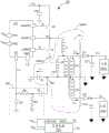
图1为依据本发明所实施的双输出LLC谐振电源转换器100。FIG. 1 shows a dual output LLC
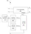
图2显示依据本发明所实施的LLC控制器102。FIG. 2 shows an
图3A显示工作信号DTH与临界值VCSP-OCP之间的关系。FIG. 3A shows the relationship between the operating signalDTH and the threshold VCSP-OCP .
图3B显示工作信号DTH与临界值VCSP-OCP之间的关系。FIG. 3B shows the relationship between the operating signalDTH and the threshold VCSP-OCP .
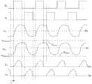
图4显示当上臂开关HS与下臂开关LS的工作周期大约都是50%时,图1与图2一些信号波形。FIG. 4 shows some signal waveforms in FIG. 1 and FIG. 2 when the duty cycles of the upper arm switch HS and the lower arm switch LS are about 50%.
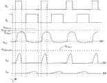
图5显示当上臂开关HS的工作周期是25%时,图1与图2一些信号波形。Fig. 5 shows some signal waveforms of Fig. 1 and Fig. 2 when the duty cycle of the upper arm switch HS is 25%.
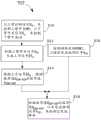
图6显示使用于图1中的LLC谐振电源转换器100内的控制方法M01。FIG. 6 shows a control method M01 used in the LLC
100 LLC谐振电源转换器100 LLC resonant power converter
102 LLC控制器102 LLC Controller
108 检测电路108 detection circuit
202 工作周期检测器202 duty cycle detector
204P、204N 临界值生成器204P, 204N Threshold Generator
206 过电流保护器206 overcurrent protector
208 开启时间控制器208 Open time controller
1041、1042 负载1041, 1042 load
1061、1062 反馈电路1061, 1062 feedback circuit
CA、CB 电容CA, CB capacitance
CL 电容CL capacitance
CO1、CO2 输出电容CO1, CO2 output capacitance
D1、D2 二极管D1, D2 Diodes
DTH、DTL 工作信号DTH ,DTL working signal
GNDIN 接地线GNDIN ground wire
HS 上臂开关HS upper arm switch
ICL 电流ICL current
ID1、ID2 感应电流ID1 , ID2 induction current
Lm、Lr 电感Lm, Lr inductance
LP 主绕组LP main winding
LS 下臂开关LS lower arm switch
LS1、LS2 二次侧绕组LS1, LS2 secondary side winding
M01 控制方法M01 control method
ND 连接点ND connection point
RA、RB 电阻RA, RB resistors
RSNT 谐振电路RSNT resonant circuit
S10、S12、S14、S16、S18 步骤S10, S12, S14, S16, S18 steps
SH 上臂控制信号SH upper arm control signal
SL 下臂控制信号SL lower arm control signal
SOCP 保护信号SOCP protection signal
TF 变压器TF Transformer
VCS 电流检测信号VCS current sense signal
VCSN-OCP、VCSP-OCP 临界值VCSN-OCP , VCSP-OCP critical value
VCSP-H、VCSP-L、VCSN-H、VCSN-L 固定常数值VCSP-H , VCSP-L , VCSN-H , VCSN-L fixed constant values
VFB1、VFB2 反馈信号VFB1 , VFB2 feedback signal
VIN 输入电源VIN input power supply
VO1、VO2 输出电源VO1 , VO2 output power supply
具体实施方式Detailed ways
在本说明书中,有一些相同的符号,其表示具有相同或是类似之结构、功能、原理的元件,且为业界具有一般知识能力者可以依据本说明书之教导而推知。为说明书之简洁度考量,相同之符号的元件将不再重述。In this specification, there are some same symbols, which represent elements with the same or similar structure, function, and principle, and can be inferred by those with general knowledge in the industry based on the teaching of this specification. For the sake of brevity in the description, elements with the same symbols will not be repeated.
本发明虽然以APWM的双输出LLC谐振电源转换器为例,但本发明并不限于此。在其他实施例中,本发明也可以使用任何其他类型的谐振电源转换器。Although the present invention takes an APWM dual-output LLC resonant power converter as an example, the present invention is not limited thereto. In other embodiments, any other type of resonant power converter may also be used with the present invention.
在本发明的一实施例中,一双输出LLC谐振电源转换器中的一LLC控制器提供两个临界值,来分别判断两个输出是否发生过电流事件,而这两个临界值可以依据驱动一谐振电路的一个功率开关之工作周期而改变,可以避免过电流保护被误触发。In an embodiment of the present invention, an LLC controller in a dual-output LLC resonant power converter provides two critical values to respectively determine whether an over-current event occurs in the two outputs, and the two critical values can be determined according to driving a The duty cycle of a power switch of the resonant circuit is changed, which can avoid false triggering of the over-current protection.
图1为依据本发明所实施的双输出LLC谐振电源转换器100。LLC谐振电源转换器100将输入电源VIN,转换为输出电源VO1与VO2,分别对负载1041与1042供电。FIG. 1 shows a dual output LLC
上臂开关HS与下臂开关LS电性串接于输入电源VIN与接地线GNDIN之间,用来驱动谐振电路RSNT,使谐振电路RSNT震荡。谐振电路RSNT包含有变压器TF与电容CL。变压器TF中的主绕组LP与两个二次侧绕组LS1与LS2相互电感耦合。变压器TF中的电感Lr与Lm表示变压器TF的主绕组LP的串接漏感与并联漏感。主绕组LP与电容CL通过连接点ND相串联。在其他实施例中,谐振电路RSNT可以有不同的架构,并不限于图1中的结构。The upper arm switch HS and the lower arm switch LS are electrically connected in series between the input power VIN and the ground line GNDIN for driving the resonant circuit RSNT to make the resonant circuit RSNT oscillate. The resonant circuit RSNT includes a transformer TF and a capacitor CL. The primary winding LP in the transformer TF is inductively coupled to the two secondary windings LS1 and LS2. The inductance Lr and Lm in the transformer TF represent the series leakage inductance and the parallel leakage inductance of the main winding LP of the transformer TF. The main winding LP is connected in series with the capacitor CL through the connection point ND. In other embodiments, the resonant circuit RSNT may have different structures, and is not limited to the structure shown in FIG. 1 .
谐振电路RSNT震荡时,二次侧绕组LS1与LS2会生成感应电流ID1与ID2,通过二极管D1与D2的整流,可以在输出电容CO1与CO2上建立起输出电源VO1与VO2。When the resonant circuit RSNT oscillates, the secondary side windings LS1 and LS2 will generate induced currentsID1 and ID2 , which can be rectified by the diodes D1 and D2 to establish output power supplies VO1 and VO2 on the output capacitors CO1 and CO2.
输出电源VO1与VO2可以通过反馈电路1061与1062,分别生成反馈信号VFB1与VFB2。LLC控制器102提供上臂控制信号SH与下臂控制信号SL,分别控制上臂开关HS与下臂开关LS。依据反馈信号VFB1与VFB2,LLC控制器102可以决定上臂开关HS与下臂开关LS的开启时间(ONtime),也就是导通时间。The output power supplies VO1 and VO2 can generate feedback signals VFB1 and VFB2 respectively through the
LLC谐振电源转换器100包含有检测电路108,由电阻RA、RB以及电容CA与CB所构成,彼此连接如同图1举例所示。检测电路108连接到连接点ND,用来检测谐振电路RSNT中跨于电容CL上的电压,具以生成电流检测信号VCS。电流检测信号VCS只是检测信号的一种,其他实施例中,检测电路108可以提供不同于电流检测信号VCS的检测信号。The LLC
图2显示依据本发明所实施的LLC控制器102,包含有开启时间控制器208、工作周期检测器202、临界值生成器204P与204N、以及过电流保护器206。FIG. 2 shows the
开启时间控制器208依据反馈信号VFB1与VFB2,生成上臂控制信号SH与下臂控制信号SL,分别控制上臂开关HS与下臂开关LS,也决定了上臂开关HS与下臂开关LS的开启时间。开启时间控制器208也架构来使得上臂开关HS与下臂开关LS实现零电压切换(zerovoltage switching,ZVS),也就是大约在一开关的一通道跨压约为0V时,开启该开关,可以减少开关损失。The turn-on time controller 208 generates the upper arm control signalSH and the lower arm control signal S L according to the feedback signals VFB1 and VFB2 , respectively controls the upper arm switch HS and the lower arm switchLS , and also determines the upper arm switch HS and the lower arm switch LS. of the opening time. The turn-on time controller 208 is also configured to enable the upper arm switch HS and the lower arm switch LS to realize zero voltage switching (ZVS), that is, when the cross voltage of a channel of a switch is about 0V, the switch is turned on, which can reduce switching loss.
在图2中,工作周期检测器202依据上臂控制信号SH,提供工作信号DTH,代表上臂开关HS的工作周期。工作信号DTH可以代表0%到100%中的一数值。工作信号DTL代表下臂开关LS的工作周期,可以通过工作信号DTH类推得知,因为工作信号DTL与工作信号DTH彼此互补,相加大约为1。举例来说,当工作信号DTH为35%(代表上臂开关HS的工作周期为35%)时,互补的工作信号DTL(代表上臂开关HS的工作周期)是65%。在另一实施例中,工作周期检测器202可以依据下臂控制信号SL,来生成并提供工作信号DTL,而工作信号DTH可以类推得知。In FIG. 2 , the
图2中,临界值生成器204P与204N依据工作信号DTH,分别提供临界值VCSP-OCP与临界值VCSN-OCP。在某些状态中,工作信号DTH的变化,会导致临界值VCSP-OCP或临界值VCSN-OCP的改变。图3A显示工作信号DTH与临界值VCSP-OCP之间的关系。当工作信号DTH大于35%时,临界值VCSP-OCP大约为不随工作信号DTH改变的固定常数值VCSP-L;当工作信号DTH小于15%时,临界值VCSP-OCP大约为不随工作信号DTH改变的固定常数值VCSP-H;当工作信号DTH介于15%与35%之间时,临界值VCSP-OCP随着工作信号DTH的变化而线性的改变。类似的,图3B显示工作信号DTH与临界值VCSN-OCP之间的关系。当工作信号DTH介于65%与85%之间时,临界值VCSN-OCP随着工作信号DTH的变化而线性的改变。在工作信号DTH小于65%或大于85%时,临界值VCSN-OCP分别是不随工作信号DTH改变的固定常数值VCSN-L与固定常数值VCSN-H,如同图3B所示。在一实施例中,四个固定常数值VCSP-H、VCSP-L、VCSN-H、VCSN-L都为正值。In FIG. 2 , the
图4显示当上臂开关HS与下臂开关LS的工作周期大约都是50%时,图1与图2一些信号波形。从上到下,图4中的信号波形分别是上臂控制信号SH、下臂控制信号SL、流过电容CL的电流ICL、电流检测信号VCS、在二次侧分别流过二极管D1与D2的感应电流ID1与ID2。举例来说,图4的信号波形可能发生在图1中的负载1041与1042均为中载的情形。FIG. 4 shows some signal waveforms in FIG. 1 and FIG. 2 when the duty cycles of the upper arm switch HS and the lower arm switch LS are about 50%. From top to bottom, the signal waveforms in Figure 4 are the upper arm control signalSH , the lower arm control signal SL , the current ICL flowing through the capacitor CL, the current detection signal VCS , and the diode D1 flowing through the secondary side respectively. and D2 sense currents ID1 and ID2 . For example, the signal waveform in FIG. 4 may occur when the
如果忽略上臂开关HS与下臂开关LS都为关闭时的空载时间(dead time),从图4的上臂控制信号SH与下臂控制信号SL可知,当下图4中的上臂开关HS与下臂开关LS的工作周期大约都是50%,也就是工作信号DTH为50%。根据图3A与3B,图4中的临界值VCSP-OCP与VCSN-OCP会分别为固定常数值VCSH-L与VCSL-L。If ignoring the dead time when both the upper arm switch HS and the lower arm switch LS are closed, it can be known from the upper arm control signalSH and the lower arm control signal SL in FIG. 4 that the upper arm switch HS and the lower arm switch LS in FIG. The duty cycle of the lower arm switch LS is about 50%, that is, the duty signal DTH is 50%. According to FIGS. 3A and 3B , the critical values VCSP-OCP and VCSN-OCP in FIG. 4 are fixed constant values VCSH-L and VCSL-L, respectively.
请参阅图2与图4。图2中过电流保护器206依据临界值VCSP-OCP与临界值VCSN-OCP,以及从检测电路108所提供的电流检测信号VCS,来决定是否输出电源VO1与VO2其中之一发生过电流事件,来触发过电流保护(over current protection,OCP)。Please refer to Figure 2 and Figure 4. In FIG. 2 , the
举例来说,如果过电流保护器206发现电流检测信号VCS超过了临界值VCSP-OCP,且发生次数达一定的连续次数,过电流保护器206就认定输出电源VO1发生了过电流事件,触发OCP。类似的,如果过电流保护器206发现电流检测信号VCS低于临界值-VCSN-OCP,且发生次数达一定的连续次数,过电流保护器206就认定输出电源VO2发生了过电流事件,触发OCP。For example, if the
图4显示当下电流检测信号VCS变化于临界值VCSP-OCP与-VCSN-OCP所界定地容许范围内。因此,在图4的信号波形中,过电流保护器206不会触发OCP。FIG. 4 shows that the variation of the current detection signal VCS is within the allowable range defined by the critical values VCSP-OCP and -VCSN-OCP . Therefore, in the signal waveform of FIG. 4 , the OCP will not be triggered by the
当OCP触发时,过电流保护器206认定过电流事件发生,通过保护信号SOCP,过电流保护器206禁能开启时间控制器208,控制上臂开关HS与下臂开关LS,使得谐振电路RSNT随着能量的损耗而停止震荡。如此,谐振电源转换器100停止供应电能给输出电源VO1与VO2。只要上臂开关HS与下臂开关LS任何一个维持关闭(不导通),谐振电路RSNT的震荡就会渐渐停止。举例来说,在一实施例中,当OCP被触发时,过电流保护器206使得上臂开关HS与下臂开关LS都持续保持关闭的状态。在另一个实施例中,当OCP被触发时,上臂开关HS与下臂开关LS其中之一保持关闭,而另一保持开启。When the OCP is triggered, the
图5显示当上臂开关HS的工作周期(工作信号DTH)是25%时,图1与图2一些信号波形。工作信号DTH是25%,同时意味了下臂开关LS的工作周期(工作信号DTL)为75%。举例来说,图5的信号波形可能发生在图1中的负载1041为中载,而负载1042为轻载的情形。根据图3A中所显示的工作信号DTH与临界值VCSP-OCP之间的关系,因为上臂开关HS的工作周期是25%,所以图5中的临界值VCSP-OCP大约为固定常数值VCSP-H与固定常数值VCSP-L的中间值。图5中,电流检测信号VCS依然位于临界值VCSP-OCP与-VCSN-OCP所界定的容许范围之内,因此,过电流保护器206也不会触发OCP。FIG. 5 shows some signal waveforms in FIG. 1 and FIG. 2 when the duty cycle of the upper arm switch HS (the duty signalDTH ) is 25%. The duty signal DTH is 25%, which means that the duty cycle of the lower arm switch LS (the duty signalDTL ) is 75%. For example, the signal waveform in FIG. 5 may occur when the load 1041 in FIG. 1 is a medium load and the
假设图5中的临界值VCSP-OCP还是如同图4一样,还是为固定常数值VCSP-L。那明显的,尽管此时图1中的负载1041为中载,没有过电流事件发生,但输出电源VO1将会被误认为发生了过电流事件,OCP将会被触发,因为电流检测信号VCS的峰值确实超过了固定常数值VCSP-L,如同图5所显示的。换言之,依据图3A,当工作信号DTH(上臂开关HS的工作周期)少于35%时,增加临界值VCSP-OCP,可以预防误认输出电源VO1发生了过电流事件。类似的,依据图3B,当工作信号DTH大于65%时,增加临界值VCSN-OCP,可以预防误认输出电源VO2发生了过电流事件。Assume that the critical value VCSP-OCP in FIG. 5 is still the same as that in FIG. 4 , and is still a fixed constant value VCSP-L . Obviously, even though the load 1041 in Fig. 1 is medium load at this time and no over-current event occurs, the output power VO1 will be mistaken for an over-current event, and the OCP will be triggered, because the current detection signal V The peak value ofCS does exceed the fixed constant value VCSP-L , as shown in FIG. 5 . In other words, according to FIG. 3A , when the operating signalDTH (the duty cycle of the upper arm switch HS) is less than 35%, increasing the threshold VCSP-OCP can prevent misidentification of an overcurrent event occurring in the output power VO1 . Similarly, according to FIG. 3B , when the working signal DTH is greater than 65%, increasing the threshold VCSN-OCP can prevent misidentification that an overcurrent event has occurred in the output power VO2 .
简单的说,临界值VCSP-OCP与-VCSN-OCP可以界定一容许范围,作为容许范围的两边界。过电流保护器206依据这容许范围以及电流检测信号VCS来触发OCP。从图3A与3B可以发现,当工作信号DTH介于35%到65%的中间区域时,临界值VCSP-OCP与-VCSN-OCP都是不随工作周期变化的固定值,所以容许范围是一标准范围,从固定常数值-VCSN-L到VCSP-L。当工作信号DTH小于35%,位于中间区域之外后,临界值VCSP-OCP随着工作信号DTH减少而增加,这容许范围转变为一相对宽范围,含盖了标准范围。当工作信号DTH大于65%,位于中间区域之外后,临界值VCSN-OCP随着工作信号DTH增加而增加,这容许范围转变为另一相对宽范围,也含盖了标准范围。In short, the critical values VCSP-OCP and -VCSN-OCP can define an allowable range as two boundaries of the allowable range. The
图6显示使用于图1中的LLC谐振电源转换器100内的控制方法M01。请同时参阅图1、图2与图6。在步骤S10,上臂控制信号SH与下臂控制信号SL,分别控制上臂开关HS与下臂开关LS。在步骤S12,工作周期检测器202依据上臂控制信号SH,提供工作信号DTH,代表上臂开关HS的工作周期。在步骤S14,临界值生成器204P与204N依据工作信号DTH,分别提供临界值VCSP-OCP与临界值VCSN-OCP。在步骤S16,检测电路108检测谐振电路RSNT,具以生成电流检测信号VCS。在步骤S18,过电流保护器206依据临界值VCSP-OCP与临界值VCSN-OCP,以及从检测电路108所提供的电流检测信号VCS,来检测发生过电流事件,并触发过电流保护。FIG. 6 shows a control method M01 used in the LLC
以上所述仅为本发明之较佳实施例,凡依本发明申请专利范围所做之均等变化与修饰,皆应属本发明之涵盖范围。The above descriptions are only preferred embodiments of the present invention, and all equivalent changes and modifications made according to the scope of the patent application of the present invention shall fall within the scope of the present invention.
Claims (10)
Translated fromChinesePriority Applications (1)
| Application Number | Priority Date | Filing Date | Title |
|---|---|---|---|
| CN202111419334.9ACN116191362A (en) | 2021-11-26 | 2021-11-26 | Control method of power converter and LLC controller |
Applications Claiming Priority (1)
| Application Number | Priority Date | Filing Date | Title |
|---|---|---|---|
| CN202111419334.9ACN116191362A (en) | 2021-11-26 | 2021-11-26 | Control method of power converter and LLC controller |
Publications (1)
| Publication Number | Publication Date |
|---|---|
| CN116191362Atrue CN116191362A (en) | 2023-05-30 |
Family
ID=86433135
Family Applications (1)
| Application Number | Title | Priority Date | Filing Date |
|---|---|---|---|
| CN202111419334.9APendingCN116191362A (en) | 2021-11-26 | 2021-11-26 | Control method of power converter and LLC controller |
Country Status (1)
| Country | Link |
|---|---|
| CN (1) | CN116191362A (en) |
- 2021
- 2021-11-26CNCN202111419334.9Apatent/CN116191362A/enactivePending
Similar Documents
| Publication | Publication Date | Title |
|---|---|---|
| TWI672896B (en) | Active clamp flyback converters and control methods thereof | |
| US7830130B2 (en) | Forward power converter controllers | |
| US10658934B2 (en) | Quasi-resonant converter with efficient light-load operation and method therefor | |
| KR100665782B1 (en) | Switching power supply | |
| US8339817B2 (en) | Method of operating a resonant power converter and a controller therefor | |
| US8339813B2 (en) | Burst mode resonant power converter with high conversion efficiency | |
| TWI687034B (en) | Active clamp flyback converter capable of switching operation modes | |
| KR102116705B1 (en) | Converter and driving method thereof | |
| US20090201705A1 (en) | Energy converting apparatus, and semiconductor device and switching control method used therein | |
| EP0993105A1 (en) | Control of power transfer in a flyback converter by modulating the off-phase in function of the load | |
| TWI796013B (en) | Power controller and control method for power converter | |
| CN110380628B (en) | Power conversion control chip and power adapter | |
| CN112398347B (en) | Switching power converter, method for controlling the same, and packaged integrated circuit | |
| US20050174813A1 (en) | High efficiency power converter with synchronous rectification | |
| GB2448741A (en) | Current sensing and overload protection of a switch mode power converter | |
| US20080239761A1 (en) | Forward power converter controllers | |
| TWI445291B (en) | Methods and power controllers for primary side control | |
| CN112532066A (en) | Novel zero-voltage switching control circuit and method and voltage converter | |
| CN113632354A (en) | Soft start of resonant converter | |
| JP3221185B2 (en) | Switching power supply | |
| CN112953175A (en) | Isolated voltage conversion system and primary side control circuit and method | |
| CN114400899B (en) | Novel zero-voltage switching control circuit, method and voltage converter | |
| TWI813059B (en) | Llc controller and control method for power converter | |
| CN111030479B (en) | Active-clamp flyback power converter and associated control method | |
| US6208089B1 (en) | Discharge-lamp lighting circuit |
Legal Events
| Date | Code | Title | Description |
|---|---|---|---|
| PB01 | Publication | ||
| PB01 | Publication | ||
| SE01 | Entry into force of request for substantive examination | ||
| SE01 | Entry into force of request for substantive examination |