CN116180419A - A glass fiber cloth cloth surface automatic dust removal device - Google Patents
A glass fiber cloth cloth surface automatic dust removal deviceDownload PDFInfo
- Publication number
- CN116180419A CN116180419ACN202310360662.9ACN202310360662ACN116180419ACN 116180419 ACN116180419 ACN 116180419ACN 202310360662 ACN202310360662 ACN 202310360662ACN 116180419 ACN116180419 ACN 116180419A
- Authority
- CN
- China
- Prior art keywords
- shaft
- sprocket
- power motor
- mounting frame
- glass fiber
- Prior art date
- Legal status (The legal status is an assumption and is not a legal conclusion. Google has not performed a legal analysis and makes no representation as to the accuracy of the status listed.)
- Granted
Links
- 239000000428dustSubstances0.000titleclaimsabstractdescription49
- 239000004744fabricSubstances0.000titleclaimsabstractdescription31
- 239000003365glass fiberSubstances0.000titleclaimsabstractdescription23
- 230000007246mechanismEffects0.000claimsabstractdescription28
- 238000004140cleaningMethods0.000claimsabstractdescription18
- 238000004804windingMethods0.000claimsdescription43
- 230000005540biological transmissionEffects0.000claimsdescription9
- 244000309464bullSpecies0.000claimsdescription6
- 238000009434installationMethods0.000claimsdescription6
- 239000000835fiberSubstances0.000description7
- 238000010586diagramMethods0.000description3
- 238000000034methodMethods0.000description3
- 239000002699waste materialSubstances0.000description3
- 230000009471actionEffects0.000description2
- 230000003247decreasing effectEffects0.000description1
- 238000002474experimental methodMethods0.000description1
- 238000012986modificationMethods0.000description1
- 230000004048modificationEffects0.000description1
- 230000008569processEffects0.000description1
- 239000000047productSubstances0.000description1
- 239000002994raw materialSubstances0.000description1
- 239000013589supplementSubstances0.000description1
Images


Classifications
- D—TEXTILES; PAPER
- D06—TREATMENT OF TEXTILES OR THE LIKE; LAUNDERING; FLEXIBLE MATERIALS NOT OTHERWISE PROVIDED FOR
- D06G—MECHANICAL OR PRESSURE CLEANING OF CARPETS, RUGS, SACKS, HIDES, OR OTHER SKIN OR TEXTILE ARTICLES OR FABRICS; TURNING INSIDE-OUT FLEXIBLE TUBULAR OR OTHER HOLLOW ARTICLES
- D06G1/00—Beating, brushing, or otherwise mechanically cleaning or pressure cleaning carpets, rugs, sacks, hides, or other skin or textile articles or fabrics
- B—PERFORMING OPERATIONS; TRANSPORTING
- B65—CONVEYING; PACKING; STORING; HANDLING THIN OR FILAMENTARY MATERIAL
- B65H—HANDLING THIN OR FILAMENTARY MATERIAL, e.g. SHEETS, WEBS, CABLES
- B65H16/00—Unwinding, paying-out webs
- B65H16/10—Arrangements for effecting positive rotation of web roll
- B65H16/103—Arrangements for effecting positive rotation of web roll in which power is applied to web-roll spindle
- B—PERFORMING OPERATIONS; TRANSPORTING
- B65—CONVEYING; PACKING; STORING; HANDLING THIN OR FILAMENTARY MATERIAL
- B65H—HANDLING THIN OR FILAMENTARY MATERIAL, e.g. SHEETS, WEBS, CABLES
- B65H18/00—Winding webs
- B65H18/08—Web-winding mechanisms
- B65H18/10—Mechanisms in which power is applied to web-roll spindle
- B—PERFORMING OPERATIONS; TRANSPORTING
- B65—CONVEYING; PACKING; STORING; HANDLING THIN OR FILAMENTARY MATERIAL
- B65H—HANDLING THIN OR FILAMENTARY MATERIAL, e.g. SHEETS, WEBS, CABLES
- B65H19/00—Changing the web roll
- B65H19/22—Changing the web roll in winding mechanisms or in connection with winding operations
- B65H19/30—Lifting, transporting, or removing the web roll; Inserting core
Landscapes
- Engineering & Computer Science (AREA)
- Mechanical Engineering (AREA)
- Textile Engineering (AREA)
- Treatment Of Fiber Materials (AREA)
- Preliminary Treatment Of Fibers (AREA)
Abstract
Description
Translated fromChinese技术领域technical field
本发明属于机械技术领域,涉及一种玻璃纤维布布面自动除尘装置。The invention belongs to the technical field of machinery and relates to an automatic dust removal device for a glass fiber cloth surface.
背景技术Background technique
玻璃纤维布是无捻粗纱平纹织物,其强度主要在织物的经纬方向上,对于要求经向或纬向强度高的场合,也可以织成单向布,它可以在经向或纬向布置较多的无捻粗纱,单经向布,单纬向布。玻璃纤维布由于其原料纤维本身的特殊性,其表面带有大量粉尘,同时,通常也会带有一些废纤维,因此,设计出一种玻璃纤维布布面自动除尘装置是很有必要的。Glass fiber cloth is a non-twisted roving plain weave fabric whose strength is mainly in the warp and weft directions of the fabric. For occasions that require high warp or weft strength, it can also be woven into unidirectional cloth. It can be arranged in the warp or weft direction. Many rovings, single warp cloth, single weft cloth. Due to the particularity of the raw material fiber itself, glass fiber cloth has a lot of dust on its surface, and at the same time, it usually contains some waste fibers. Therefore, it is necessary to design an automatic dust removal device for glass fiber cloth.
发明内容Contents of the invention
本发明的目的是针对现有的技术存在上述问题,提出了一种玻璃纤维布布面自动除尘装置。The purpose of the present invention is to propose a kind of glass fiber cloth surface automatic dedusting device in view of the problems mentioned above in the prior art.
本发明的目的可通过下列技术方案来实现:一种玻璃纤维布布面自动除尘装置,包括基座,其特征在于,所述基座上依次设有放卷机构、除尘机构和收卷机构,所述除尘机构包括安装架、两个滚筒和两个吸尘罩,所述安装架固定在基座中部,所述两个滚筒通过可拆卸的方式水平转动安装在安装架上,且两个滚筒呈对称布置,所述滚筒还与一能使其同步转动的驱动结构相连,所述两个吸尘罩也呈对称安装在安装架上,且吸尘罩位于滚筒上方,所述吸尘罩内侧具有若干吸尘口,所述吸尘罩外侧连接有若干第一支管,所述第一支管上具有第一阀门,所述第一支管通过第一总管和三通接头的第一端相连通,所述三通接头的第二端通过连接管和吸尘器相连通,所述安装架上水平安装有与滚筒相配合的清理盒,且滚筒底部的一部分位于清理盒内,所述清理盒底部连接有若干第二支管,所述第二支管上具有第二阀门,所述第二支管通过第二总管和三通接头的第三端相连通。The purpose of the present invention can be achieved through the following technical proposals: a glass fiber cloth cloth surface automatic dust removal device, comprising a base, characterized in that, the base is sequentially provided with an unwinding mechanism, a dust removal mechanism and a winding mechanism, The dust removal mechanism includes a mounting frame, two rollers and two dust suction hoods, the mounting frame is fixed in the middle of the base, the two rollers are detachably mounted on the mounting frame by horizontal rotation, and the two rollers Arranged symmetrically, the drum is also connected to a drive structure that can rotate synchronously. The two dust collection covers are also symmetrically installed on the mounting frame, and the dust collection cover is located above the drum. The inner side of the dust collection cover There are several dust suction ports, and several first branch pipes are connected to the outside of the dust suction hood, and the first branch pipes have a first valve, and the first branch pipes communicate with the first end of the tee joint through the first main pipe, The second end of the three-way joint communicates with the vacuum cleaner through a connecting pipe. A cleaning box matching the roller is installed horizontally on the mounting frame, and a part of the bottom of the roller is located in the cleaning box. The bottom of the cleaning box is connected with a Several second branch pipes have second valves on the second branch pipes, and the second branch pipes communicate with the third end of the tee joint through the second main pipe.
所述放卷机构包括第一支架、主放卷轴、从放卷轴、第一动力电机、第一链轮一、第一链轮二、第一链带、小齿轮和大齿轮,所述第一支架安装在基座一端,所述主放卷轴和从放卷轴分别水平转动安装在第一支架两侧,且主放卷轴和从放卷轴两者之间可拆卸连接有放卷筒,所述第一动力电机安装在第一支架上,且第一动力电机的输出轴水平设置,所述第一链轮一安装在第一动力电机的输出轴端部,所述第一支架一侧还安装有传动轴,所述第一链轮二和小齿轮分别安装在传动轴两端,所述第一链带套设在第一链轮二与第一链轮一之间,所述大齿轮安装在主放卷轴端部,且大齿轮与小齿轮相啮合。The unwinding mechanism includes a first support, a main unwinding shaft, a slave unwinding shaft, a first power motor, a first sprocket one, a first sprocket two, a first chain belt, a pinion and a bull gear. The bracket is installed at one end of the base, and the main unwinding shaft and the slave unwinding shaft are respectively horizontally rotated and installed on both sides of the first bracket, and a reel is detachably connected between the main unwinding shaft and the slave unwinding shaft. A power motor is installed on the first bracket, and the output shaft of the first power motor is arranged horizontally, the first sprocket is installed on the output shaft end of the first power motor, and one side of the first bracket is also installed with The transmission shaft, the first sprocket two and the pinion are installed at both ends of the transmission shaft respectively, the first chain belt is sleeved between the first sprocket two and the first sprocket one, and the large gear is installed on The end of the main unwinding shaft, and the large gear meshes with the small gear.
所述收卷机构包括第二支架、第一收卷轴、第二收卷轴和第二动力电机,所述第二支架安装在基座另一端,所述第一收卷轴和第二收卷轴分别水平转动安装在第二支架上,且收卷筒能放置在第一收卷轴和第二收卷轴两者之间,所述第一收卷轴端部分别固定有第二链轮一和第二链轮二,所述第二收卷轴端部固定有第二链轮三,所述第二链轮三和第二链轮一之间套设有第二链带一,所述第二动力电机安装在第二支架上,且第二动力电机的输出轴水平设置,所述第二动力电机的输出轴端部安装有第二链轮四,所述第二链轮四与第二链轮二之间套设有第二链带二;所述第二支架两侧分别与导出臂中部转动连接,所述导出臂上端水平滑动连接有调节杆,所述调节杆一端和顶推块相连,所述调节杆另一端和手柄相连,且导出臂上端还螺纹连接有锁紧螺栓,所述导出臂下端和气缸的活塞杆端部转动连接,所述气缸的缸体与第二支架侧部转动连接,且气缸的活塞杆倾斜朝下布置。The winding mechanism includes a second support, a first winding shaft, a second winding shaft and a second power motor, the second support is installed at the other end of the base, and the first winding shaft and the second winding shaft are respectively horizontal Rotation is installed on the second bracket, and the winding cylinder can be placed between the first winding shaft and the second winding shaft, and the ends of the first winding shaft are respectively fixed with the second sprocket one and the second sprocket Two, the second sprocket three is fixed on the end of the second winding shaft, the second chain belt one is sleeved between the second sprocket three and the second sprocket one, and the second power motor is installed on On the second support, and the output shaft of the second power motor is arranged horizontally, the output shaft end of the second power motor is equipped with a second sprocket four, between the second sprocket four and the second sprocket two The
所述第二支架上还安装有操作台。An operating table is also installed on the second support.
所述滚筒上具有呈环形阵列分布的若干长条毛刷。There are several elongated brushes distributed in a circular array on the cylinder.
所述安装架上水平转动设置有导入轴和导出轴,且导入轴、吸尘罩、滚筒和导出轴呈由上至下依次布置。A lead-in shaft and a lead-out shaft are arranged horizontally on the mounting frame, and the lead-in shaft, the dust hood, the roller and the lead-out shaft are arranged sequentially from top to bottom.
所述安装架上水平转动安装有舒展轴,所述舒展轴端部安装有第三链轮一,所述安装架上还固定有第三动力电机,且第三动力电机的输出轴水平设置,所述第三动力电机的输出轴端部安装有第三链轮二,所述第三链轮二与第三链轮一之间套设有第三链带。A stretching shaft is mounted on the mounting frame for horizontal rotation, and a
所述驱动结构包括主动拨盘、从动槽轮、第四动力电机和两个齿轮,所述两个齿轮安装在滚筒端部,且两个齿轮之间相互啮合,所述第四动力电机安装在安装架上,且第四动力电机的输出轴水平设置,所述从动槽轮安装在其中一个滚筒端部,所述从动槽轮上具有呈均匀分布的若干导槽,所述主动拨盘安装在动力电机的输出轴端部,所述主动拨盘上还具有与导槽相配合的拨动柱,所述清理盒两侧安装有竖直导轨,所述导轨上滑动连接有滑块,所述滑块之间连接有往复框,所述往复框上安装有两排辅助杆,所述辅助杆上具有若干倒刺部,所述辅助杆上还具有工作槽,所述清理盒外端安装有与辅助杆相配合的刀片,且刀片的刀刃部能位于工作槽内,其中一个滑块和联动杆下端转动连接,所述联动杆上端和主动拨盘转动连接。The drive structure includes a driving dial, a driven sheave, a fourth power motor and two gears, the two gears are installed at the end of the drum, and the two gears are engaged with each other, and the fourth power motor is installed On the installation frame, and the output shaft of the fourth power motor is set horizontally, the driven sheave is installed on the end of one of the drums, and the driven sheave has several guide grooves evenly distributed on it, and the driving pulley The disk is installed at the end of the output shaft of the power motor, and the driving dial also has a toggle column matched with the guide groove. Vertical guide rails are installed on both sides of the cleaning box, and sliders are slidably connected to the guide rails. , a reciprocating frame is connected between the sliders, and two rows of auxiliary rods are installed on the reciprocating frame. There are several barbs on the auxiliary rods, and there are working grooves on the auxiliary rods. The end is equipped with a blade matched with the auxiliary rod, and the blade portion of the blade can be located in the working groove, one of the sliders is rotatably connected to the lower end of the linkage rod, and the upper end of the linkage rod is rotatably connected to the driving dial.
所述往复框上具有供玻璃纤维布通过的让位缺口。The reciprocating frame has a gap for the glass fiber cloth to pass through.
与现有技术相比,本玻璃纤维布布面自动除尘装置具有该优点:Compared with the prior art, this glass fiber cloth surface automatic dust removal device has the advantages:
本发明中通过放卷机构、除尘机构和收卷机构等结构,可对卷状的玻璃纤维布进行有效除尘,处理完后又可以将其重新打卷,在除尘过程中,通过布置了辊筒和吸尘罩两者相配合,从而可将玻璃纤维布布面上的粉尘和废纤维去除掉。In the present invention, through the structure of unwinding mechanism, dust removal mechanism and winding mechanism, the rolled glass fiber cloth can be effectively dedusted, and it can be re-rolled after treatment. During the dedusting process, rollers are arranged Cooperate with the vacuum hood, so that the dust and waste fibers on the surface of the glass fiber cloth can be removed.
附图说明Description of drawings
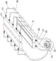
图1是本发明的平面结构示意图;Fig. 1 is a schematic plan view of the present invention;
图2是本发明中放卷机构的立体结构示意图;Fig. 2 is the three-dimensional structural representation of unwinding mechanism in the present invention;
图3是本发明中收卷机构的立体结构示意图;Fig. 3 is a three-dimensional structural schematic diagram of a winding mechanism in the present invention;
图4是本发明中除尘机构的立体结构示意图;Fig. 4 is the three-dimensional structure schematic diagram of dedusting mechanism in the present invention;
图5是本发明中驱动结构的立体结构示意图;Fig. 5 is a three-dimensional schematic diagram of the driving structure in the present invention;
图6是A处的局部放大图;Figure 6 is a partial enlarged view at A;
图中,1、基座;2、第一动力电机;3、第一链轮一;4、第一链带;5、第一支架;6、大齿轮;7、小齿轮;8、第一链轮二;9、清理盒;10、滚筒;11、安装架;12、导入轴;13、吸尘罩;14、导出臂;15、第二收卷轴;16、第一收卷轴;17、操作台;18、气缸;19、第二支架;20、第二动力电机;21、舒展轴;22、导出轴;23、传动轴;24、锁紧螺栓;25、顶推块;26、调节杆;27、手柄;28、第二链轮三;29、第二链带一;30、第二链轮一;31、第二链轮二;32、第二链带二;33、第二链轮四;34、三通接头;35、吸尘器;36、第二总管;37、第二支管;38、第二阀门;39、第一总管;40、第一支管;41、第一阀门;42、齿轮;43、往复框;44、滑块;45、导轨;46、辅助杆;46a、倒刺部;46b、工作槽;47、刀片;48、拨动柱;49、从动槽轮;50、主动拨盘;51、联动杆;52、主放卷轴;53、从放卷轴;54、导槽。In the figure, 1, the base; 2, the first power motor; 3, the first sprocket one; 4, the first chain belt; 5, the first bracket; 6, the large gear; 7, the pinion; 8, the first Sprocket two; 9, cleaning box; 10, drum; 11, mounting frame; 12, lead-in shaft; 13, dust cover; 14, export arm; 15, second rewinding shaft; 16, first rewinding shaft; 17, Operating table; 18, cylinder; 19, second bracket; 20, second power motor; 21, stretch shaft; 22, export shaft; 23, transmission shaft; 24, locking bolt; 25, push block; 26, adjustment Rod; 27, handle; 28, the second chain wheel three; 29, the second chain belt one; 30, the second chain wheel one; 31, the second chain wheel two; 32, the second chain belt two; 33, the second Sprocket four; 34, tee joint; 35, vacuum cleaner; 36, second main pipe; 37, second branch pipe; 38, second valve; 39, first main pipe; 40, first branch pipe; 41, first valve; 42, gear; 43, reciprocating frame; 44, slider; 45, guide rail; 46, auxiliary rod; 46a, barbed part; 46b, working groove; 47, blade; 48, toggle column; 49, driven sheave ; 50, the active dial; 51, the linkage lever; 52, the main unwinding reel; 53, from the unwinding reel; 54, the guide groove.
具体实施方式Detailed ways
以下是本发明的具体实施例并结合附图,对本发明的技术方案作进一步的描述,但本发明并不限于这些实施例。The following are specific embodiments of the present invention and in conjunction with the accompanying drawings, the technical solutions of the present invention are further described, but the present invention is not limited to these embodiments.
如图1-图6所示,本玻璃纤维布布面自动除尘装置,包括基座1,基座1上依次设有放卷机构、除尘机构和收卷机构,除尘机构包括安装架11、两个滚筒10和两个吸尘罩13,安装架11固定在基座1中部,两个滚筒10通过可拆卸的方式水平转动安装在安装架11上,具体的:滚筒10上具有呈环形阵列分布的若干长条毛刷,该滚筒10可以采用市场上买到的现有产品;且两个滚筒10呈对称布置,滚筒10还与一能使其同步转动的驱动结构相连,两个吸尘罩13也呈对称安装在安装架11上,且吸尘罩13位于滚筒10上方,吸尘罩13内侧具有若干吸尘口,吸尘口的数量可以根据实际需要进行增加或者减少;吸尘罩13外侧连接有若干第一支管40,第一支管40上具有第一阀门41,第一支管40通过第一总管39和三通接头的第一端相连通,三通接头34的第二端通过连接管和吸尘器35相连通,吸尘器35采用市场上可以买到的现有工业吸尘器35;安装架11上水平安装有与滚筒10相配合的清理盒9,且滚筒10底部的一部分位于清理盒9内,清理盒9底部连接有若干第二支管37,第二支管37上具有第二阀门38,第二支管37通过第二总管36和三通接头34的第三端相连通,在本实施例中,第一阀门41和第二阀门38均采用市场上可以买到的手动阀门,通过其可控制管道内的气体通过量。As shown in Figures 1-6, the automatic dust removal device for glass fiber cloth covers includes a
放卷机构包括第一支架5、主放卷轴52、从放卷轴53、第一动力电机2、第一链轮一3、第一链轮二8、第一链带4、小齿轮7和大齿轮6,第一支架5安装在基座1一端,主放卷轴52和从放卷轴53分别水平转动安装在第一支架5两侧,且主放卷轴52和从放卷轴53两者之间可拆卸连接有放卷筒,第一动力电机2安装在第一支架5上,且第一动力电机2的输出轴水平设置,第一链轮一3安装在第一动力电机2的输出轴端部,第一支架5一侧还安装有传动轴23,第一链轮二8和小齿轮7分别安装在传动轴23两端,第一链带4套设在第一链轮二8与第一链轮一3之间,大齿轮6安装在主放卷轴52端部,且大齿轮6与小齿轮7相啮合;将放卷筒采用现有方式安装到主放卷轴52和从放卷轴53之间,通过第一动力电机2带动第一链轮一3转动,第一链轮一3通过第一链带4带动第一链轮二8转动,第一链轮二8带动传动轴23转动,传动轴23带动小齿轮7转动,小齿轮7带动大齿轮6转动,大齿轮6主放卷轴52转动,从而实现对放卷筒的转动。The unwinding mechanism comprises the
收卷机构包括第二支架19、第一收卷轴16、第二收卷轴15和第二动力电机20,第二支架19安装在基座1另一端,第一收卷轴16和第二收卷轴15分别水平转动安装在第二支架19上,且收卷筒能放置在第一收卷轴16和第二收卷轴15两者之间,第一收卷轴16端部分别固定有第二链轮一30和第二链轮二31,第二收卷轴15端部固定有第二链轮三28,第二链轮三28和第二链轮一30之间套设有第二链带一29,第二动力电机20安装在第二支架19上,且第二动力电机20的输出轴水平设置,第二动力电机20的输出轴端部安装有第二链轮四33,第二链轮四33与第二链轮二31之间套设有第二链带二32;采用以上结构,通过将收卷筒放置在第一收卷轴16和第二收卷轴15之间,通过第二动力电机20带动第二链轮四33转动,第二链轮四33通过第二链带二32带动第二链轮二31转动,第二链轮二31带动第一收卷轴16转动,在第二链轮三28、第二链轮一30和第二链带一29的作用下,使第一收卷轴16和第二收卷轴15同步带动收卷筒转动;第二支架19两侧分别与导出臂14中部转动连接,导出臂14上端水平滑动连接有调节杆26,调节杆26一端和顶推块25相连,调节杆26另一端和手柄27相连,且导出臂14上端还螺纹连接有锁紧螺栓24,导出臂14下端和气缸18的活塞杆端部转动连接,气缸18的缸体与第二支架19侧部转动连接,且气缸18的活塞杆倾斜朝下布置;第二支架19上还安装有操作台17;采用该结构,在收卷完成后,通过将顶推块25移动合适位置,通过气缸18带动导出臂14摆动,导出臂14带动顶推块25运动,在顶推块25的作用下,将位于第一收卷轴16和第二收卷轴15上的收卷筒向外顶出,使其滚动到操作台17上,从而减轻劳动强度。The winding mechanism comprises a
安装架11上水平转动设置有导入轴12和导出轴22,且导入轴12、吸尘罩13、滚筒10和导出轴22呈由上至下依次布置。The
安装架11上水平转动安装有舒展轴21,舒展轴21端部安装有第三链轮一,安装架11上还固定有第三动力电机,且第三动力电机的输出轴水平设置,第三动力电机的输出轴端部安装有第三链轮二,第三链轮二与第三链轮一之间套设有第三链带;采用该结构,通过第三动力电机带动第三链轮二转动,第三链轮二通过第三链带带动第三链轮一转动,第三链轮二使舒展轴21转动,从而可将除尘完的玻璃纤维布展开。Horizontal rotation on the
驱动结构包括主动拨盘50、从动槽轮49、第四动力电机和两个齿轮42,两个齿轮42安装在滚筒10端部,且两个齿轮42之间相互啮合,第四动力电机安装在安装架11上,且第四动力电机的输出轴水平设置,从动槽轮49安装在其中一个滚筒10端部,从动槽轮49上具有呈均匀分布的若干导槽54,主动拨盘50安装在动力电机的输出轴端部,主动拨盘50上还具有与导槽54相配合的拨动柱48,清理盒9两侧安装有竖直导轨45,导轨45上滑动连接有滑块44,滑块44之间连接有往复框43,往复框43上安装有两排辅助杆46,辅助杆46上具有若干倒刺部46a,辅助杆46上还具有工作槽46b,清理盒9外端安装有与辅助杆46相配合的刀片47,在本实施例中,刀片47通过连接座与清理盒9相连;且刀片47的刀刃部能位于工作槽46b内,其中一个滑块44和联动杆51下端转动连接,联动杆51上端和主动拨盘50转动连接;往复框43上具有供玻璃纤维布通过的让位缺口;采用该结构,通过第四动力电机带动主动拨盘50转动,主动拨盘50的拨动柱48与动槽轮的导槽54相配合,并在两个齿轮42的配合下,使滚筒10间歇性转动,滚筒10可将玻璃纤维布布上的废纤维和粉尘刷落,同时,由于主动拨盘50还可以带动联动杆51运动,进而使滑块44沿着导轨45上下往复运动,最终使往复框43能带动辅助杆46上下移动,在辅助杆46的作用下,可将缠绕在滚筒10的长条毛刷处的长纤维去除掉,而每次辅助杆46向下运动时,辅助杆46的工作槽46b会经过刀片47的刀刃,从而将辅助杆46上的长纤维切断,由于清理盒9处也具有吸力,从而可将切断后的长纤维或者粉尘吸走,从而可大大提高滚筒10的清洁能力和清洁时长。The drive structure includes a
以上部件均为通用标准件或本技术领域人员知晓的部件,其结构和原理都为本技术人员均可通过技术手册得知或通过常规实验方法获知。The above components are common standard parts or components known to those skilled in the art, and their structures and principles are known to those skilled in the art through technical manuals or through conventional experimental methods.
本文中所描述的具体实施例仅仅是对本发明精神作举例说明。本发明所属技术领域的技术人员可以对所描述的具体实施例做各种各样的修改或补充或采用类似的方式替代,但并不会偏离本发明的精神或者超越所附权利要求书所定义的范围。The specific embodiments described herein are merely illustrative of the spirit of the invention. Those skilled in the art to which the present invention belongs can make various modifications or supplements to the described specific embodiments or adopt similar methods to replace them, but they will not deviate from the spirit of the present invention or go beyond the definition of the appended claims range.
Claims (7)
Translated fromChinesePriority Applications (1)
| Application Number | Priority Date | Filing Date | Title |
|---|---|---|---|
| CN202310360662.9ACN116180419B (en) | 2023-04-03 | 2023-04-03 | Automatic dust collector of glass fiber cloth cover |
Applications Claiming Priority (1)
| Application Number | Priority Date | Filing Date | Title |
|---|---|---|---|
| CN202310360662.9ACN116180419B (en) | 2023-04-03 | 2023-04-03 | Automatic dust collector of glass fiber cloth cover |
Publications (2)
| Publication Number | Publication Date |
|---|---|
| CN116180419Atrue CN116180419A (en) | 2023-05-30 |
| CN116180419B CN116180419B (en) | 2024-10-29 |
Family
ID=86444590
Family Applications (1)
| Application Number | Title | Priority Date | Filing Date |
|---|---|---|---|
| CN202310360662.9AActiveCN116180419B (en) | 2023-04-03 | 2023-04-03 | Automatic dust collector of glass fiber cloth cover |
Country Status (1)
| Country | Link |
|---|---|
| CN (1) | CN116180419B (en) |
Citations (13)
| Publication number | Priority date | Publication date | Assignee | Title |
|---|---|---|---|---|
| US5482562A (en)* | 1992-04-02 | 1996-01-09 | Abernathy; Frank W. | Method and an apparatus for the removal of fibrous material from a rotating shaft |
| US8286292B1 (en)* | 2009-08-31 | 2012-10-16 | Roy Carl Jacobson | Rug cleaning system |
| CN202594459U (en)* | 2012-06-13 | 2012-12-12 | 瑞安市三联包装机械厂 | Automatic unloading mechanism of high-speed splitting machine |
| KR20160003656A (en)* | 2013-03-15 | 2016-01-11 | 악티에볼라겟 엘렉트로룩스 | Vacuum cleaner agitator cleaner with power control |
| CN106923747A (en)* | 2017-04-25 | 2017-07-07 | 苏州市春菊电器有限公司 | A kind of round brush twister device for excising and its cleaning appliance for cleaning appliance |
| CN207267759U (en)* | 2017-09-26 | 2018-04-24 | 温州万润机械有限公司 | The shedding mechanism of laminating machine |
| KR20190019534A (en)* | 2017-08-18 | 2019-02-27 | 박남숙 | Brush cleaning device and vacuum cleaner having the same |
| CN112246720A (en)* | 2020-11-16 | 2021-01-22 | 江苏美的清洁电器股份有限公司 | Rolling brush cleaning device |
| CN112295971A (en)* | 2020-11-19 | 2021-02-02 | 吴红卫 | Textile fabric winding equipment and method for textile mill and textile technology |
| CN212800955U (en)* | 2020-07-03 | 2021-03-26 | 杭州明华纺织有限公司 | Cloth inspecting machine with dust removal function |
| CN214342097U (en)* | 2019-11-06 | 2021-10-08 | 尚科宁家(中国)科技有限公司 | Cleaning device |
| CN217479809U (en)* | 2022-06-23 | 2022-09-23 | 海宁万联经编股份有限公司 | Surface fabric surface dust removal device for surface fabric processing |
| CN217579434U (en)* | 2021-12-06 | 2022-10-14 | 新天伦服装配料(惠州)有限公司 | Weave mark production with clean dust collector |
- 2023
- 2023-04-03CNCN202310360662.9Apatent/CN116180419B/enactiveActive
Patent Citations (13)
| Publication number | Priority date | Publication date | Assignee | Title |
|---|---|---|---|---|
| US5482562A (en)* | 1992-04-02 | 1996-01-09 | Abernathy; Frank W. | Method and an apparatus for the removal of fibrous material from a rotating shaft |
| US8286292B1 (en)* | 2009-08-31 | 2012-10-16 | Roy Carl Jacobson | Rug cleaning system |
| CN202594459U (en)* | 2012-06-13 | 2012-12-12 | 瑞安市三联包装机械厂 | Automatic unloading mechanism of high-speed splitting machine |
| KR20160003656A (en)* | 2013-03-15 | 2016-01-11 | 악티에볼라겟 엘렉트로룩스 | Vacuum cleaner agitator cleaner with power control |
| CN106923747A (en)* | 2017-04-25 | 2017-07-07 | 苏州市春菊电器有限公司 | A kind of round brush twister device for excising and its cleaning appliance for cleaning appliance |
| KR20190019534A (en)* | 2017-08-18 | 2019-02-27 | 박남숙 | Brush cleaning device and vacuum cleaner having the same |
| CN207267759U (en)* | 2017-09-26 | 2018-04-24 | 温州万润机械有限公司 | The shedding mechanism of laminating machine |
| CN214342097U (en)* | 2019-11-06 | 2021-10-08 | 尚科宁家(中国)科技有限公司 | Cleaning device |
| CN212800955U (en)* | 2020-07-03 | 2021-03-26 | 杭州明华纺织有限公司 | Cloth inspecting machine with dust removal function |
| CN112246720A (en)* | 2020-11-16 | 2021-01-22 | 江苏美的清洁电器股份有限公司 | Rolling brush cleaning device |
| CN112295971A (en)* | 2020-11-19 | 2021-02-02 | 吴红卫 | Textile fabric winding equipment and method for textile mill and textile technology |
| CN217579434U (en)* | 2021-12-06 | 2022-10-14 | 新天伦服装配料(惠州)有限公司 | Weave mark production with clean dust collector |
| CN217479809U (en)* | 2022-06-23 | 2022-09-23 | 海宁万联经编股份有限公司 | Surface fabric surface dust removal device for surface fabric processing |
Also Published As
| Publication number | Publication date |
|---|---|
| CN116180419B (en) | 2024-10-29 |
Similar Documents
| Publication | Publication Date | Title |
|---|---|---|
| CN206613633U (en) | A kind of dedusting humidification integration apparatus of spinnery | |
| CN115387104B (en) | Textile equipment is used in production of antibiotic waterproof surface fabric | |
| CN102886358B (en) | Automatic cleaning and drying device for air valve | |
| CN114751241A (en) | Dust collector is used in surface fabric textile processing | |
| CN217971867U (en) | Visual detection equipment for detecting defect of cloth cover | |
| CN113844903A (en) | Make things convenient for garbage collection's automation line | |
| CN116180419A (en) | A glass fiber cloth cloth surface automatic dust removal device | |
| CN110937436A (en) | Cloth collecting machine with automatic discharge function | |
| CN209756365U (en) | Fabric compounding device | |
| CN109208311B (en) | Weaving equipment that possesses dust removal function | |
| CN112605017A (en) | Intelligent belt cleaning device of yarn suction hollow shaft for textile manufacturing | |
| CN219508248U (en) | Textile fabric cleaning structure for textile conveying device | |
| CN218902853U (en) | Full-automatic magnetic box flushing device | |
| CN217579434U (en) | Weave mark production with clean dust collector | |
| CN202877170U (en) | Air valve automatic cleaning and drying device | |
| CN215364174U (en) | A cloth levels device for clothing production | |
| CN213652906U (en) | Cloth belt cleaning device for textile processing | |
| CN115607045A (en) | Cotton yarn production waste recovery device and recovery method | |
| CN214723237U (en) | Multifunctional polishing, cleaning and baking machine for reed | |
| CN211972554U (en) | Weaving dust collection device for weaving equipment | |
| CN209453261U (en) | A kind of plate polishing machine | |
| CN209737372U (en) | Reciprocating continuous automatic sand blasting machine | |
| CN208274158U (en) | A kind of disposable emulsion and PVC glove pickoff | |
| CN112299095A (en) | Automatic cloth cover cleaner of roll checking integrated machine | |
| CN209618578U (en) | One kind being convenient for clean automatic winder |
Legal Events
| Date | Code | Title | Description |
|---|---|---|---|
| PB01 | Publication | ||
| PB01 | Publication | ||
| SE01 | Entry into force of request for substantive examination | ||
| SE01 | Entry into force of request for substantive examination | ||
| GR01 | Patent grant | ||
| GR01 | Patent grant |