CN116176881A - A microgravity simulation test system for fine manipulation of a space dexterous arm in a narrow area - Google Patents
A microgravity simulation test system for fine manipulation of a space dexterous arm in a narrow areaDownload PDFInfo
- Publication number
- CN116176881A CN116176881ACN202211706396.2ACN202211706396ACN116176881ACN 116176881 ACN116176881 ACN 116176881ACN 202211706396 ACN202211706396 ACN 202211706396ACN 116176881 ACN116176881 ACN 116176881A
- Authority
- CN
- China
- Prior art keywords
- space
- dexterous
- motion simulator
- arm
- rope
- Prior art date
- Legal status (The legal status is an assumption and is not a legal conclusion. Google has not performed a legal analysis and makes no representation as to the accuracy of the status listed.)
- Pending
Links
Images


Classifications
- B—PERFORMING OPERATIONS; TRANSPORTING
- B64—AIRCRAFT; AVIATION; COSMONAUTICS
- B64G—COSMONAUTICS; VEHICLES OR EQUIPMENT THEREFOR
- B64G7/00—Simulating cosmonautic conditions, e.g. for conditioning crews
Landscapes
- Engineering & Computer Science (AREA)
- Remote Sensing (AREA)
- Aviation & Aerospace Engineering (AREA)
- Manipulator (AREA)
- Management, Administration, Business Operations System, And Electronic Commerce (AREA)
Abstract
Translated fromChinese
Description
Translated fromChinese技术领域technical field
本发明涉及卫星试验设备与系统,具体属于一种空间灵巧臂狭小区域精细操作的微重力模拟试验系统。The invention relates to satellite test equipment and a system, in particular to a microgravity simulation test system for precise operation in a narrow area of a space dexterous arm.
背景技术Background technique
近年来,利用空间灵巧臂在狭小受限环境下执行灵巧精细操作任务已成为在轨服务领域的重要手段。灵巧机械臂具有结构柔顺性好、灵活度高、轻量化等优点,适合于执行非结构化环境下传统刚性臂无法完成的操作任务。然而地面重力环境导致低结构刚度的灵巧机械臂产生显著的结构变形,对机械臂的臂形和末端定位精度产生了严重影响,对其地面演示验证造成困难。同时,空间灵巧臂需要辅助末端视觉伺服控制来提高其末端定位能力,因此验证复杂在轨光照环境对于灵巧臂末端相机测量能力的影响也具有重要意义。In recent years, the use of space dexterous arms to perform dexterous and fine manipulation tasks in small and restricted environments has become an important means in the field of on-orbit servicing. The dexterous robotic arm has the advantages of good structural compliance, high flexibility, and light weight, and is suitable for performing operational tasks that traditional rigid arms cannot complete in an unstructured environment. However, the ground gravity environment leads to significant structural deformation of the dexterous manipulator with low structural stiffness, which has a serious impact on the arm shape and end positioning accuracy of the manipulator, making it difficult to demonstrate on the ground. At the same time, the spatial dexterous arm needs auxiliary terminal visual servo control to improve its terminal positioning ability, so it is also of great significance to verify the influence of complex on-orbit lighting environment on the measurement capability of the dexterous arm terminal camera.
例如,在地面演示验证空间灵巧机械臂伸入目标卫星太阳帆板狭缝中切割连接螺栓任务时,重力的影响导致空间灵巧臂的臂形下坠,以及由狭缝外进入狭缝内剧烈的光照环境变化,都将导致灵巧臂的臂形精度和末端定位精度下降。因此,高保真的空间灵巧臂地面试验系统的关键在于对空间微重力环境和复杂光照环境的高精度模拟。For example, when the ground demonstrates that the space dexterous manipulator extends into the slit of the solar panel of the target satellite to cut the connecting bolts, the influence of gravity causes the arm shape of the space dexterous arm to fall, and the intense light enters the slit from outside the slit Environmental changes will lead to a decline in the arm shape accuracy and end positioning accuracy of the dexterous arm. Therefore, the key to a high-fidelity space dexterous arm ground test system lies in the high-precision simulation of the space microgravity environment and complex lighting environment.
发明内容Contents of the invention
本发明解决的技术问题是:克服现有技术的不足,提供了一种空间灵巧臂狭小区域精细操作的微重力模拟试验系统,解决了空间灵巧臂在狭小受限环境下操作的地面试验验证问题。The technical problem solved by the present invention is to overcome the deficiencies of the prior art, provide a microgravity simulation test system for the fine operation of the space dexterous arm in a narrow area, and solve the ground test verification problem of the space dexterous arm operating in a narrow and restricted environment .
本发明的技术解决方案是:Technical solution of the present invention is:
一种空间灵巧臂狭小区域精细操作的微重力模拟试验系统,包括光学暗室、分布式红外测量相机、太阳光模拟装置、服务星运动模拟器、目标星运动模拟器、悬吊式微重力模拟系统和大理石气浮台;A microgravity simulation test system for precise operation in a small area of a space dexterous arm, including an optical darkroom, a distributed infrared measurement camera, a sunlight simulation device, a service star motion simulator, a target star motion simulator, a suspended microgravity simulation system and Marble air flotation table;
悬吊式微重力模拟系统和大理石气浮台均置于光学暗室内,服务星运动模拟器和目标星运动模拟器放置于大理石气浮台的表面;The suspended microgravity simulation system and the marble air bearing table are placed in the optical darkroom, and the service star motion simulator and the target star motion simulator are placed on the surface of the marble air bearing table;
服务星运动模拟器包括服务星气浮基座、灵巧臂驱动控制箱、空间灵巧臂本体、灵巧臂末端视觉相机,灵巧臂驱动控制箱连接于服务星气浮基座上,且用于控制空间灵巧臂本体,灵巧臂末端视觉相机连接于空间灵巧臂本体的末端;The service star motion simulator includes the service star air bearing base, the smart arm drive control box, the space smart arm body, and the vision camera at the end of the smart arm. The smart arm drive control box is connected to the service star air bearing base and is used to control the space The smart arm body, the vision camera at the end of the smart arm is connected to the end of the space smart arm body;
目标星运动模拟器包括目标星气浮基座、折叠帆板、帆板基座、帆板锁紧螺栓,帆板基座连接于目标星气浮基座,帆板锁紧螺栓将折叠帆板9固定在帆板基座上;The target star motion simulator includes the target star air float base, folding sailboard, sailboard base, sailboard locking bolts, the sailboard base is connected to the target star air floatation base, and the sailboard locking bolts will fold the sailboard 9 fixed on the sailboard base;
悬吊式微重力模拟系统用于将将重力补偿量施加在空间灵巧臂本体上,且分布式红外测量相机、太阳光模拟装置连接于悬吊式微重力模拟系统;The suspended microgravity simulation system is used to apply the gravity compensation amount on the space dexterous arm body, and the distributed infrared measurement camera and the sunlight simulation device are connected to the suspended microgravity simulation system;
太阳光模拟装置用于模拟光照;Sunlight simulation device is used to simulate lighting;
分布式红外测量相机采集服务星运动模拟器和目标星运动模拟器的位姿信息。The distributed infrared measurement camera collects the pose information of the service star motion simulator and the target star motion simulator.
所述悬吊式微重力模拟系统包括外框架,外框架架设于大理石气浮台的上方;The suspended microgravity simulation system includes an outer frame, and the outer frame is erected above the marble air bearing table;
外框架上设有垂直运动绳索收放模组、水平运动绳索收放模组,垂直运动绳索收放模组的绳索连接于空间灵巧臂本体的末端、并用于驱动空间灵巧臂本体的末端竖直移动,水平运动绳索收放模组的绳索连接空间灵巧臂本体的中部位置、并用于驱动空间灵巧臂本体的中部进行水平移动,进而将将重力补偿量施加在空间灵巧臂本体上。The outer frame is equipped with a vertical movement rope retractable module and a horizontal movement rope retractable module. The rope of the vertical movement rope retractable module is connected to the end of the space dexterous arm body and is used to drive the end of the space dexterous arm body to be vertical. Movement, horizontal movement The rope of the rope retractable module is connected to the middle of the space dexterous arm body, and is used to drive the middle of the space dexterous arm body to move horizontally, and then apply the gravity compensation amount to the space dexterous arm body.
还包括空间动力学目标机、地面试验系统控制台、运动模拟器控制台、无线通信模块;空间动力学目标机、地面试验系统控制台、运动模拟器控制台三者之间通过Ethercat网络进行双向数据通信;空间动力学目标机通过Ethercat总线设置太阳光模拟装置的初始光照信息,并随时间变化改变光照,模拟灵巧臂作业时的空间光照环境。It also includes the space dynamics target machine, the ground test system console, the motion simulator console, and the wireless communication module; the space dynamics target machine, the ground test system console, and the motion simulator console are two-way through the Ethercat network Data communication; space dynamics The target machine sets the initial lighting information of the sunlight simulation device through the Ethercat bus, and changes the lighting with time to simulate the space lighting environment when the smart arm works.
所述空间动力学目标机根据服务星运动模拟器和目标星运动模拟器的位姿信息解算服务星运动模拟器的路径方程,并将服务星运动模拟器的路径方程发送给运动模拟器控制台;The space dynamics target machine solves the path equation of the service star motion simulator according to the pose information of the service star motion simulator and the target star motion simulator, and sends the path equation of the service star motion simulator to the motion simulator control tower;
运动模拟器控制台根据服务星运动模拟器的路径方程计算服务星运动模拟器上推力器的控制量,然后通过无线通信模块将服务星运动模拟器上推力器的控制量发送给服务星运动模拟器,控制其向目标星运动模拟器接近;The motion simulator console calculates the control amount of the thruster on the service star motion simulator according to the path equation of the service star motion simulator, and then sends the control amount of the thruster on the service star motion simulator to the service star motion simulation through the wireless communication module device, controlling it to approach the target star motion simulator;
服务星运动模拟器到达目标星运动模拟器附近后,运动模拟器控制台通过无线通信模块将轨迹规划信息发送给服务星运动模拟器上承载的空间灵巧机械臂,空间灵巧机械臂的末端视觉相机测得的相对位姿信息通过无线通信模块返回给运动模拟器控制台用于下一段轨迹规划,逐步引导空间灵巧臂末端到达目标星运动模拟器所承载的折叠帆板附近;After the service star motion simulator arrives near the target star motion simulator, the motion simulator console sends the trajectory planning information to the space dexterous manipulator carried on the service star motion simulator through the wireless communication module, and the end vision camera of the space dexterous manipulator The measured relative pose information is returned to the motion simulator console through the wireless communication module for the next segment of trajectory planning, and gradually guides the end of the space dexterous arm to reach the vicinity of the folding sailboard carried by the target star motion simulator;
分布式红外测量相机采集空间灵巧机械臂本体上的标记点位置信息,并将标记点位置信息返回给地面试验系统控制台计算出空间灵巧机械臂本体的臂形信息和末端位姿信息。The distributed infrared measurement camera collects the position information of the marked points on the body of the space dexterous manipulator, and returns the position information of the marked points to the console of the ground test system to calculate the arm shape information and the terminal pose information of the space dexterous manipulator body.
所述悬吊式微重力模拟系统连接空间灵巧臂本体的悬吊点处连接六维力传感器。The suspension point of the suspended microgravity simulation system connected to the main body of the space dexterous arm is connected with a six-dimensional force sensor.
所述悬吊式微重力模拟系统悬吊点上的六维力传感器采集空间灵巧机械臂本体悬吊处的重力分布信息,并将悬吊处的重力分布信息返回地面试验系统控制台,地面试验系统控制台根据空间灵巧机械臂的臂形信息、末端位姿信息和悬吊点处重力分布信息计算空间灵巧机械臂本体的重力补偿量,并解算为悬吊式微重力模拟系统的每个绳索收放模组的电机力矩控制量,然后将电机控制量发送给垂直运动绳索收放模组和/或水平运动绳索收放模组,垂直运动绳索收放模组和/或水平运动绳索收放模组通过绳索拉力将重力补偿量施加在空间灵巧机械臂上,抵消地面重力环境对空间灵巧机械臂产生的变形。The six-dimensional force sensor on the suspension point of the suspended microgravity simulation system collects the gravity distribution information at the suspension place of the space smart manipulator body, and returns the gravity distribution information at the suspension place to the console of the ground test system, and the ground test system The console calculates the gravity compensation amount of the space dexterous manipulator body according to the arm shape information of the space dexterous manipulator, the terminal pose information, and the gravity distribution information at the suspension point, and solves it for each rope retraction of the suspended microgravity simulation system. The motor torque control amount of the release module, and then send the motor control amount to the vertical motion rope retraction module and/or the horizontal motion rope retraction module, the vertical motion rope retraction module and/or the horizontal motion rope retraction module The group applies the gravity compensation amount to the space dexterous manipulator through the tension of the rope to offset the deformation of the space dexterous manipulator caused by the gravity environment on the ground.
所述外框架设置有导轨,垂直运动绳索收放模组1包括横梁和连接于横梁的第一绳索,横梁的两端滑动连接于导轨,第一绳索的底端为第二悬吊点,第二悬吊点连接于空间灵巧臂本体的末端。The outer frame is provided with a guide rail, and the vertical movement rope retractable module 1 includes a beam and a first rope connected to the beam, the two ends of the beam are slidably connected to the guide rail, the bottom end of the first rope is the second suspension point, and the second rope is connected to the beam. The two suspension points are connected to the ends of the space dexterous arm body.
所述水平运动绳索收放模组包括两个分别滑动连接于一侧导轨的滑动部、以及第二绳索,第二绳索的两端分别连接到一个滑动部上,第二绳索上的一点为第一悬挂点,第一悬挂点连接于空间灵巧臂本体的中部位置。The horizontal motion rope retractable module includes two sliding parts that are respectively slidably connected to one side of the guide rail, and a second rope. The two ends of the second rope are respectively connected to a sliding part. One point on the second rope is A suspension point, the first suspension point is connected to the middle position of the space dexterous arm body.
进一步,所述的无线通信模块、分布式红外测量相机、太阳光模拟装置、服务星运动模拟器、目标星运动模拟器、悬吊式微重力模拟系统和大理石气浮台都布置在光学暗室中,避免庞杂光源干扰。分布式红外测量相机发射的红外波段与服务星运动模拟器上所承载的空间灵巧机械臂末端视觉相机的接受波段错开,避免对空间灵巧机械臂末端相对位姿的测量产生干扰。Further, the wireless communication module, the distributed infrared measurement camera, the sunlight simulation device, the service star motion simulator, the target star motion simulator, the suspended microgravity simulation system and the marble air flotation table are all arranged in the optical darkroom, Avoid the interference of complex light sources. The infrared band emitted by the distributed infrared measurement camera is staggered from the receiving band of the visual camera at the end of the space dexterous manipulator carried on the service star motion simulator, so as to avoid interference with the measurement of the relative pose of the end of the space dexterous manipulator.
进一步,垂直运动绳索收放模组、水平运动绳索收放模组可以通过控制绳索的收放来控制绳索末端的拉力,通过悬吊点上搭载的六维力传感器采集受力状态信息用以补偿重力,绳索收放模组和还可以分别在导轨和横梁上移动,扩大运动补偿的范围。此外,外框架顶部还搭载分布式红外测量相机和太阳光模拟装置。Further, the vertical motion rope retraction module and the horizontal motion rope retraction module can control the tension at the end of the rope by controlling the retraction of the rope, and collect the force state information through the six-dimensional force sensor mounted on the suspension point to compensate Gravity, the rope retractable module and the module can also move on the guide rail and the beam respectively, expanding the range of motion compensation. In addition, a distributed infrared measurement camera and a sunlight simulation device are mounted on the top of the outer frame.
进一步,气浮基座可以通过气压控制悬浮在大理石气浮台上,消除气浮台平面内的三个自由度方向上的摩擦阻力。灵巧臂驱动控制箱内含有电机驱动模块,用于驱动空间灵巧臂本体弯曲运动,灵巧臂末端视觉相机可以测量与目标点的相对位姿信息,使灵巧臂运动至目标点附近执行操作任务。Furthermore, the air-floating base can be suspended on the marble air-floating table through air pressure control, eliminating the frictional resistance in the directions of three degrees of freedom in the plane of the air-floating table. The smart arm drive control box contains a motor drive module, which is used to drive the bending movement of the space smart arm body. The vision camera at the end of the smart arm can measure the relative pose information with the target point, so that the smart arm moves to the vicinity of the target point to perform the operation task.
综上所述,本申请至少包括以下有益技术效果:In summary, the present application at least includes the following beneficial technical effects:
(1)可同时模拟空间环境中的光照情况和微重力情况,高保真的模拟空间灵巧臂的实际作业环境。(1) Simultaneously simulate the light conditions and microgravity conditions in the space environment, and simulate the actual working environment of the space dexterous arm with high fidelity.
(2)采用气浮系统和悬吊机构结合的微重力补偿方案,可以提供更多方向上的更为精确的重力补偿而不用受限于绳索和机构之间的干涉碰撞。(2) The microgravity compensation scheme combined with the air flotation system and the suspension mechanism can provide more accurate gravity compensation in more directions without being limited by the interference and collision between the rope and the mechanism.
(3)设计水平方向和垂直方向运动的绳索收放装置,兼顾了灵巧臂高重力补偿精度需要更多悬吊绳索和狭小空间作业无法容纳过多悬吊绳索的矛盾,利用垂直方向的单绳悬吊重力补偿灵巧臂末端,实现灵巧臂末端可以深入帆板狭缝的狭小空间作业。(3) Design the rope retractable device for horizontal and vertical movement, taking into account the contradiction between the high gravity compensation accuracy of the dexterous arm that requires more suspension ropes and the narrow space operation that cannot accommodate too many suspension ropes, using a single rope in the vertical direction Suspension gravity compensates the end of the smart arm, so that the end of the smart arm can go deep into the narrow space of the windsurfing slit.
附图说明Description of drawings
图1为空间灵巧臂狭小区域精细操作的地面微重力模拟试验系统组成示意图;Figure 1 is a schematic diagram of the composition of the ground microgravity simulation test system for fine manipulation in a narrow area of the space dexterous arm;
图2为服务星运动模拟器组成示意图;Fig. 2 is a schematic diagram of the composition of the service star motion simulator;
图3为目标星运动模拟器组成示意图;Fig. 3 is a schematic diagram of the composition of the target star motion simulator;
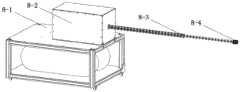
图4为悬吊式微重力模拟系统组成示意图。Figure 4 is a schematic diagram of the composition of the suspended microgravity simulation system.
附图标记说明:1、空间动力学目标机;2、地面试验系统控制台;3、运动模拟器控制台;4、无线通信模块;5、光学暗室;6、分布式红外测量相机;7、太阳光模拟装置;8、服务星运动模拟器;9、目标星运动模拟器;10、悬吊式微重力模拟系统;11、大理石气浮台;8-1、服务星气浮基座;8-2、灵巧臂驱动控制箱;8-3、空间灵巧臂本体;8-4、灵巧臂末端视觉相机;9-1、目标星气浮基座;9-2、折叠帆板;9-3、帆板基座;9-4、帆板锁紧螺栓;10-1、外框架;10-2、垂直运动绳索收放模组;10-3、水平运动绳索收放模组;10-4、第一悬吊点;10-5、导轨;10-6、横梁;10-7、第二悬吊点。Description of reference signs: 1. Space dynamics target machine; 2. Ground test system console; 3. Motion simulator console; 4. Wireless communication module; 5. Optical darkroom; 6. Distributed infrared measurement camera; 7. Sunlight simulation device; 8. Service star motion simulator; 9. Target star motion simulator; 10. Suspended microgravity simulation system; 11. Marble air flotation platform; 8-1. Service star air flotation base; 8- 2. Smart arm drive control box; 8-3. Space smart arm body; 8-4. Vision camera at the end of the smart arm; 9-1. Target star air flotation base; 9-2. Folding sailboard; 9-3. Sailboard base; 9-4, sailboard locking bolts; 10-1, outer frame; 10-2, vertical movement rope retractable module; 10-3, horizontal movement rope retractable module; 10-4, The first suspension point; 10-5, the guide rail; 10-6, the beam; 10-7, the second suspension point.
具体实施方式Detailed ways
下面结合附图和具体实施例对本申请作进一步详细的描述:Below in conjunction with accompanying drawing and specific embodiment the application is described in further detail:
空间灵巧臂狭小区域精细操作的地面微重力模拟试验系统见图1,主要包括空间动力学目标机1、地面试验系统控制台2、运动模拟器控制台3、无线通信模块4、光学暗室5、分布式红外测量相机6、太阳光模拟装置7、服务星运动模拟器8、目标星运动模拟器9、悬吊式微重力模拟系统10和大理石气浮台11。The ground microgravity simulation test system for the fine operation of the space dexterous arm in a narrow area is shown in Figure 1, which mainly includes the space dynamics target machine 1, the ground
悬吊式微重力模拟系统10和大理石气浮台11均置于光学暗室5内,服务星运动模拟器8和目标星运动模拟器9放置于大理石气浮台11的表面。服务星运动模拟器8包括服务星气浮基座8-1、灵巧臂驱动控制箱8-2、空间灵巧臂本体8-3、灵巧臂末端视觉相机8-4,灵巧臂驱动控制箱8-2连接于服务星气浮基座8-1的上表面,且用于控制空间灵巧臂本体8-3,灵巧臂末端视觉相机8-4连接于空间灵巧臂本体8-3的末端。目标星运动模拟器9包括目标星气浮基座9-1、折叠帆板9-2、帆板基座9-3、帆板锁紧螺栓9-4,帆板基座9-3连接于目标星气浮基座9-1上,帆板锁紧螺栓9-4将折叠帆板9-2固定在帆板基座9-3上,折叠帆板、帆板基座和帆板锁紧螺栓形成了灵巧臂狭小、非结构化的作业环境。The suspended
悬吊式微重力模拟系统10包括外框架10-1,外框架10-1架设于大理石气浮台11的上方。分布式红外测量相机6、太阳光模拟装置7连接于外框架10-1上。外框架10-1上设有垂直运动绳索收放模组10-2、水平运动绳索收放模组10-3、导轨10-5,垂直运动绳索收放模组10-2包括横梁10-6和连接于横梁10-6的第一绳索,横梁10-6的两端滑动连接于导轨10-5,第一绳索的底端为第二悬吊点10-7,用于连接空间灵巧臂本体8-3的末端。水平运动绳索收放模组10-3包括两个分别滑动连接于一侧导轨10-5的滑动部、以及第二绳索,第二绳索的两端分别连接到一个滑动部上,第二绳索上的一点为第一悬挂点10-4,用于连接空间灵巧臂本体8-3的中部位置。第一悬挂点和第二悬挂点均搭载有六维力传感器。垂直运动绳索收放模组10-2、水平运动绳索收放模组10-3通过控制其多连接的绳索的收放来控制绳索末端的拉力,通过悬吊点上搭载的六维力传感器采集受力状态信息,与外框架顶部搭载分布式红外测量相机所测得的位姿信息一起,进行力位协调控制,实现更高精度的灵巧臂重力补偿,绳索收放模组和还可以分别在导轨和横梁上移动,扩大运动补偿的范围。The suspended
第一绳索和第二绳索均连接有绳索收放模组,绳索收放模组用于控制绳索的收放,进而将将重力补偿量施加在空间灵巧臂本体8-3上。Both the first rope and the second rope are connected with a rope retraction module, and the rope retraction module is used to control the retraction of the rope, and then apply the gravity compensation amount to the space dexterous arm body 8-3.
服务星气浮基座8-1和目标星气浮基座9-1可以通过气压控制悬浮在大理石气浮台上,消除气浮台平面内的三个自由度方向上的摩擦阻力。灵巧臂驱动控制箱内含有电机驱动模块,用于驱动空间灵巧臂本体弯曲运动,灵巧臂末端视觉相机可以测量与目标点的相对位姿信息,使灵巧臂运动至目标点附近执行操作任务。The service star air-floating base 8-1 and the target star air-floating base 9-1 can be suspended on the marble air-floating platform through air pressure control, eliminating the frictional resistance in the directions of three degrees of freedom in the plane of the air-floating platform. The smart arm drive control box contains a motor drive module, which is used to drive the bending movement of the space smart arm body. The vision camera at the end of the smart arm can measure the relative pose information with the target point, so that the smart arm moves to the vicinity of the target point to perform the operation task.
该系统的信息流图是:空间动力学目标机1通过Ethercat总线设置太阳光模拟装置7的初始光照信息,并随时间变化改变光照,模拟灵巧臂作业时的空间光照环境;服务星运动模拟器8和目标星运动模拟器9都布置在大理石气浮台11上,分布式红外测量相机6采集两个运动模拟器的位姿信息,并通过Ethercat总线发送给空间动力学目标机1,空间动力学目标机1根据轨道动力学方程和姿态动力学方程解算服务星运动模拟器8的运动方程,并将计算结果发送给运动模拟器控制台3计算服务星运动模拟器上推力器的控制量,然后通过无线通信模块4发送给服务星运动模拟器8,控制其向目标星运动模拟器9接近;服务星运动模拟器8到达目标星运动模拟器9附近后,运动模拟器控制台3通过无线通信模块4将轨迹规划信息发送给服务星运动模拟器8上承载的空间灵巧机械臂,空间灵巧机械臂的末端视觉相机测得的相对位姿信息通过无线通信模块4返回给运动模拟器控制台3用于下一段轨迹规划,并根据空间灵巧臂动力学方程,逐步引导空间灵巧臂末端到达目标星运动模拟器9所承载的折叠帆板附近;分布式红外测量相机6采集空间灵巧机械臂上的标记点位置信息,并通过Ethercat总线返回给地面试验系统控制台2计算出空间灵巧机械臂的臂形信息和末端位姿信息。同时,悬吊式微重力模拟系统10的悬吊点上安装有六维力传感器,用于采集空间灵巧机械臂悬吊处的重力分布情况,并通过Ethercat总线返回地面试验系统控制台2,地面试验系统控制台2根据空间灵巧机械臂的臂形信息、末端位姿信息和悬吊点处重力分布信息计算空间灵巧机械臂的重力补偿量,并根据悬吊式微重力模拟系统的动力学方程,解算为悬吊式微重力模拟系统10的每个绳索收放模组(包括垂直运动绳索收放模组和/或水平运动绳索收放模组)的电机力矩控制量,然后将电机控制量通过Ethercat总线发送给悬吊式微重力模拟系统10的绳索收放模组(包括垂直运动绳索收放模组10-2和水平运动绳索收放模组10-3),绳索收放模组的力矩电机通过绳索拉力将重力补偿量施加在空间灵巧机械臂上,抵消地面重力环境对空间灵巧机械臂产生的变形。The information flow diagram of the system is: the space dynamics target machine 1 sets the initial illumination information of the
空间灵巧臂狭小区域精细操作的地面微重力模拟试验系统试验流程:The test process of the ground microgravity simulation test system for fine manipulation in a narrow area of the space dexterous arm:
1)试验准备1) Test preparation
(1)完成承载空间灵巧臂的服务星运动模拟器8和承载折叠帆板9-2的目标星运动模拟器9的充气和充电;(1) Complete inflation and charging of the service star motion simulator 8 carrying the space dexterous arm and the target star motion simulator 9 carrying the folding sailboard 9-2;
(2)启动空间动力学目标机1、地面试验系统控制台2、运动模拟器控制台3电源,启动悬吊式微重力模拟系统10、分布式红外测量相机6电源。打开承载空间灵巧臂的服务星运动模拟器8和承载折叠帆板9-2的目标星运动模拟器9的电源和气阀;(2) Start the power supply of the space dynamics target machine 1, the ground
(3)在悬吊式微重力模拟系统10内将各运动模拟器摆放到初始位置,将悬吊式微重力模拟系统10的悬吊点与空间灵巧机械臂上的支撑片连接;(3) place each motion simulator to the initial position in the suspended
(4)通过悬吊点上的六维力传感器采集空间灵巧机械臂重力分布信息,发送给地面试验系统控制台2,并由其计算出重力补偿值,发送给悬吊式微重力模拟系统10的力矩电机,补偿初始状态空间灵巧臂所受的重力,调平空间灵巧臂;(4) Collect the gravity distribution information of the space smart manipulator through the six-dimensional force sensor on the suspension point, send it to the ground
(5)关闭光学暗室5中的光源,避免庞杂光源干扰,打开太阳光模拟装置7电源,通过空间动力学目标机1总控制界面设置太阳光模拟装置7模拟灯光照,完成初始状态的光照环境模拟。(5) Turn off the light source in the
2)试验阶段2) Experimental stage
(1)分布式红外测量相机6采集服务星运动模拟器8和目标星运动模拟器9的全局位姿信息发送给空间动力学目标机1。空间动力学目标机1解算服务星运动模拟器8的运动方程,并将计算结果发送给运动模拟器控制台3计算服务星运动模拟器上推力器的控制量,然后通过无线通信模块4发送给服务星运动模拟器8,控制其向目标星运动模拟器9飞去;(1) The distributed
(2)服务星运动模拟器8到达目标星运动模拟器9附近的预设位置后与目标星运动模拟器9保持相对位姿稳定。服务星运动模拟器8所承载的空间灵巧机械臂的末端视觉相机测得与折叠帆板9-2狭缝的相对位姿信息,并通过无线通信模块4返回给运动模拟器控制台3用于轨迹规划,运动模拟器控制台3将轨迹规划信息发送给空间灵巧机械臂,空间灵巧机械臂执行相应的轨迹运动至折叠帆板9-2狭缝处;(2) After the service star motion simulator 8 reaches the preset position near the target star motion simulator 9, it maintains relative pose stability with the target star motion simulator 9 . The terminal vision camera of the space dexterous manipulator carried by the service star motion simulator 8 measures the relative pose information with the slit of the folding sailboard 9-2, and returns it to the motion simulator console 3 through the wireless communication module 4 for use in Trajectory planning, the motion simulator console 3 sends the trajectory planning information to the space dexterous manipulator, and the space dexterous manipulator executes the corresponding trajectory movement to the slit of the folding sailboard 9-2;
(3)在空间灵巧机械臂运动过程中,分布式红外测量相机6实时采集空间灵巧机械臂上的标记点位置信息,并通过Ethercat总线返回给地面试验系统控制台2即时计算出空间灵巧机械臂的臂形信息和末端位姿信息;(3) During the movement of the space dexterous manipulator, the distributed
(4)在空间灵巧机械臂运动过程中,悬吊式微重力模拟系统10悬吊点上六维力传感器采集空间灵巧机械臂悬吊点处的重力信息通过Ethercat总线返回地面试验系统控制台2;(4) During the movement of the space dexterous manipulator, the six-dimensional force sensor on the suspension point of the suspended
(5)在空间灵巧机械臂运动过程中,地面试验系统控制台2根据空间灵巧机械臂的臂形信息和末端位姿信息以及悬吊点处的重力分布信息,计算空间灵巧机械臂的重力补偿量,并解算悬吊式微重力模拟系统10的每个绳索收放模组上得到力矩控制量,然后将力矩控制量发送给悬吊式微重力模拟系统10的力矩电机,力矩电机通过绳索拉力将重力补偿量施加在空间灵巧机械臂上,抵消地面重力环境对空间灵巧机械臂产生的变形;(5) During the movement of the space dexterous manipulator, the ground
(6)空间灵巧机械臂的末端视觉相机测量折叠帆板9-2狭缝内未解锁的帆板固定螺栓的相对位姿关系,并返回给运动模拟器控制台3规划机械臂末端接近路径,根据规划的路径空间灵巧机械臂运动到帆板固定螺栓处执行预设的操作任务;(6) The end vision camera of the space dexterous manipulator measures the relative pose relationship of the un-unlocked sailboard fixing bolts in the slit of the folding sailboard 9-2, and returns it to the motion simulator console 3 to plan the approach path of the end of the manipulator, According to the planned path space, the smart robotic arm moves to the fixing bolt of the sailboard to perform the preset operation task;
(7)空间灵巧机械臂完成操作任务后安按照原来进入的路径退出帆板区域,地面试验系统控制台2发出试验停止指示,分布式红外测量相机6停止采集位置信息,地面试验系统控制台2和运动模拟器控制台3存储试验数据;(7) After the space dexterous manipulator completes the operation task, An exits the sailboard area according to the original entry path, the ground
(8)关闭太阳光模拟装置7,打开光学暗室5照明,断开空间灵巧机械臂、悬吊式微重力模拟系统10和分布式红外测量相机6电源,关闭服务星运动模拟器8和目标星运动模拟器9电源和气阀,关闭空间动力学目标机1、地面试验系统控制台2和运动模拟器控制台3电源,试验结束。(8) Close the
本发明虽然以较佳实施例公开如上,但其并不是用来限定本发明,任何本领域技术人员在不脱离本发明的精神和范围内,都可以做出可能的变动和修改,因此,本发明的保护范围应当以本发明权利要求所界定的范围为准。Although the present invention is disclosed above with preferred embodiments, it is not intended to limit the present invention, and any person skilled in the art can make possible changes and modifications without departing from the spirit and scope of the present invention. Therefore, the present invention The protection scope of the invention shall be defined by the claims of the present invention.
Claims (8)
Translated fromChinesePriority Applications (1)
| Application Number | Priority Date | Filing Date | Title |
|---|---|---|---|
| CN202211706396.2ACN116176881A (en) | 2022-12-29 | 2022-12-29 | A microgravity simulation test system for fine manipulation of a space dexterous arm in a narrow area |
Applications Claiming Priority (1)
| Application Number | Priority Date | Filing Date | Title |
|---|---|---|---|
| CN202211706396.2ACN116176881A (en) | 2022-12-29 | 2022-12-29 | A microgravity simulation test system for fine manipulation of a space dexterous arm in a narrow area |
Publications (1)
| Publication Number | Publication Date |
|---|---|
| CN116176881Atrue CN116176881A (en) | 2023-05-30 |
Family
ID=86439511
Family Applications (1)
| Application Number | Title | Priority Date | Filing Date |
|---|---|---|---|
| CN202211706396.2APendingCN116176881A (en) | 2022-12-29 | 2022-12-29 | A microgravity simulation test system for fine manipulation of a space dexterous arm in a narrow area |
Country Status (1)
| Country | Link |
|---|---|
| CN (1) | CN116176881A (en) |
Cited By (2)
| Publication number | Priority date | Publication date | Assignee | Title |
|---|---|---|---|---|
| CN117284506A (en)* | 2023-08-09 | 2023-12-26 | 南京航空航天大学 | Microgravity impact dynamics test platform and test method for aerospace adsorption mechanism |
| CN117775323A (en)* | 2024-02-23 | 2024-03-29 | 哈尔滨工业大学 | Air suspension simulation experiment system and method for robot motion under weak gravitational field |
Citations (2)
| Publication number | Priority date | Publication date | Assignee | Title |
|---|---|---|---|---|
| CN109760860A (en)* | 2018-12-11 | 2019-05-17 | 上海航天控制技术研究所 | The ground system test of non-cooperation rolling target is arrested in a kind of both arms collaboration |
| CN114261543A (en)* | 2021-12-14 | 2022-04-01 | 哈尔滨工业大学(深圳) | Ground test platform, system and method for space multi-arm spacecraft system |
- 2022
- 2022-12-29CNCN202211706396.2Apatent/CN116176881A/enactivePending
Patent Citations (2)
| Publication number | Priority date | Publication date | Assignee | Title |
|---|---|---|---|---|
| CN109760860A (en)* | 2018-12-11 | 2019-05-17 | 上海航天控制技术研究所 | The ground system test of non-cooperation rolling target is arrested in a kind of both arms collaboration |
| CN114261543A (en)* | 2021-12-14 | 2022-04-01 | 哈尔滨工业大学(深圳) | Ground test platform, system and method for space multi-arm spacecraft system |
Cited By (4)
| Publication number | Priority date | Publication date | Assignee | Title |
|---|---|---|---|---|
| CN117284506A (en)* | 2023-08-09 | 2023-12-26 | 南京航空航天大学 | Microgravity impact dynamics test platform and test method for aerospace adsorption mechanism |
| CN117284506B (en)* | 2023-08-09 | 2024-03-08 | 南京航空航天大学 | Microgravity impact dynamics test platform and test method for aerospace adsorption mechanism |
| CN117775323A (en)* | 2024-02-23 | 2024-03-29 | 哈尔滨工业大学 | Air suspension simulation experiment system and method for robot motion under weak gravitational field |
| CN117775323B (en)* | 2024-02-23 | 2024-05-03 | 哈尔滨工业大学 | Air suspension simulation experimental system and method for robot motion in weak gravitational field |
Similar Documents
| Publication | Publication Date | Title |
|---|---|---|
| CN116176881A (en) | A microgravity simulation test system for fine manipulation of a space dexterous arm in a narrow area | |
| CN106081173B (en) | Three-dimensional active suspension type spacecraft microgravity simulator | |
| CN103085992B (en) | Spatial microgravity simulation experiment system | |
| US20230182931A1 (en) | Ground test system and test method for space-oriented multi-arm spacecraft system | |
| CN101850850B (en) | Layout method of central airframe digital assembly of big plane | |
| CN114464070B (en) | Experiment platform for magnetic levitation gravity compensation of planetary vehicle based on parallel attitude adjustment | |
| CN202807110U (en) | Gas floating six-degree-of-freedom simulation satellite device of semi-active type gravity compensation structure | |
| CN107867414B (en) | Twelve-degree-of-freedom spacecraft simulator docking performance test device | |
| CN108382616B (en) | Suspension gravity compensation device based on magnetic suspension follow-up | |
| CN108621202B (en) | Multi-arm space robot cooperative fine operation ground experiment system | |
| CN104787363A (en) | Ground microgravity dynamic loading simulation mechanism for satellite | |
| CN111571563B (en) | Semi-physical simulation system and method for asteroid attachment mechanism | |
| CN104118580A (en) | Device and method for simulating low gravity | |
| CN109883642A (en) | A low-speed aircraft vehicle-mounted force measurement system | |
| CN109573097B (en) | Vehicle-mounted test method and system for aerodynamic parameters of low-speed aircraft | |
| CN106742059B (en) | Unmanned spacecraft landing simulation platform and method in bumpy environment | |
| CN113264203B (en) | A multi-objective six-degree-of-freedom microgravity ground simulation system and using method | |
| CN115561004A (en) | Space multi-branch robot ground test platform and test method | |
| CN107244430A (en) | Magnetic hangs across the yardstick checking device of the free pedestal space tasks of comprehensive compensation | |
| CN115180190B (en) | Ground simulation system and experimental method for on-orbit operation extra-cabin maintenance tool of astronaut | |
| CN114055476B (en) | Method and system for testing capture torque of space manipulator | |
| CN102913553B (en) | Multi-layer air floatation hanging device capable of performing two-dimensional friction-free long-distance movement | |
| CN111169665A (en) | Solar panel deployment test system and its operation method | |
| JPH08313388A (en) | Wind tunnel test device | |
| CN208198861U (en) | The suspention gravity-compensated device being servo-actuated based on magnetic suspension |
Legal Events
| Date | Code | Title | Description |
|---|---|---|---|
| PB01 | Publication | ||
| PB01 | Publication | ||
| SE01 | Entry into force of request for substantive examination | ||
| SE01 | Entry into force of request for substantive examination |