CN116174849A - A pressure pipeline magnetic installation welding process and its equipment - Google Patents
A pressure pipeline magnetic installation welding process and its equipmentDownload PDFInfo
- Publication number
- CN116174849A CN116174849ACN202310301898.5ACN202310301898ACN116174849ACN 116174849 ACN116174849 ACN 116174849ACN 202310301898 ACN202310301898 ACN 202310301898ACN 116174849 ACN116174849 ACN 116174849A
- Authority
- CN
- China
- Prior art keywords
- welding
- movable
- pressure pipe
- frame
- groove
- Prior art date
- Legal status (The legal status is an assumption and is not a legal conclusion. Google has not performed a legal analysis and makes no representation as to the accuracy of the status listed.)
- Granted
Links
Images


Classifications
- B—PERFORMING OPERATIONS; TRANSPORTING
- B23—MACHINE TOOLS; METAL-WORKING NOT OTHERWISE PROVIDED FOR
- B23K—SOLDERING OR UNSOLDERING; WELDING; CLADDING OR PLATING BY SOLDERING OR WELDING; CUTTING BY APPLYING HEAT LOCALLY, e.g. FLAME CUTTING; WORKING BY LASER BEAM
- B23K9/00—Arc welding or cutting
- B—PERFORMING OPERATIONS; TRANSPORTING
- B23—MACHINE TOOLS; METAL-WORKING NOT OTHERWISE PROVIDED FOR
- B23K—SOLDERING OR UNSOLDERING; WELDING; CLADDING OR PLATING BY SOLDERING OR WELDING; CUTTING BY APPLYING HEAT LOCALLY, e.g. FLAME CUTTING; WORKING BY LASER BEAM
- B23K9/00—Arc welding or cutting
- B23K9/32—Accessories
- Y—GENERAL TAGGING OF NEW TECHNOLOGICAL DEVELOPMENTS; GENERAL TAGGING OF CROSS-SECTIONAL TECHNOLOGIES SPANNING OVER SEVERAL SECTIONS OF THE IPC; TECHNICAL SUBJECTS COVERED BY FORMER USPC CROSS-REFERENCE ART COLLECTIONS [XRACs] AND DIGESTS
- Y02—TECHNOLOGIES OR APPLICATIONS FOR MITIGATION OR ADAPTATION AGAINST CLIMATE CHANGE
- Y02P—CLIMATE CHANGE MITIGATION TECHNOLOGIES IN THE PRODUCTION OR PROCESSING OF GOODS
- Y02P70/00—Climate change mitigation technologies in the production process for final industrial or consumer products
- Y02P70/10—Greenhouse gas [GHG] capture, material saving, heat recovery or other energy efficient measures, e.g. motor control, characterised by manufacturing processes, e.g. for rolling metal or metal working
Landscapes
- Engineering & Computer Science (AREA)
- Physics & Mathematics (AREA)
- Plasma & Fusion (AREA)
- Mechanical Engineering (AREA)
- Butt Welding And Welding Of Specific Article (AREA)
Abstract
Translated fromChinese
Description
Translated fromChinese技术领域technical field
本发明涉及管道焊接技术领域,具体为一种压力管道带磁安装焊接工艺及其设备。The invention relates to the technical field of pipeline welding, in particular to a pressure pipeline magnetic installation welding process and equipment thereof.
背景技术Background technique
在石油化工装置检修及工艺管线焊接施工中,焊条离焊接坡口一定距离就会被强力吸附到管道上,焊接时焊条引弧后产生的反向电流磁场与剩磁磁场相互作用使电弧向坡口外偏吹,无法形成熔池和焊缝,使带磁状态下不能实施管道焊接。In the maintenance of petrochemical equipment and the welding construction of process pipelines, the electrode will be strongly adsorbed to the pipe when it is a certain distance away from the welding groove. Blowing outside the mouth makes it impossible to form molten pool and weld seam, so that pipeline welding cannot be carried out in the magnetic state.
目前对于压力管道的坡口区进行焊接前,由于坡口区的磁性超标,进而导致无法对压力管道的坡口区进行焊接,需要人工对压力管道的坡口区进行消磁处理,不仅降低了对压力管道的焊接效率,同时还延长了对压力管道的焊接施工工期。At present, before the welding of the bevel area of the pressure pipe, because the magnetic properties of the bevel area exceed the standard, it is impossible to weld the bevel area of the pressure pipe. It is necessary to manually demagnetize the bevel area of the pressure pipe, which not only reduces the The welding efficiency of the pressure pipeline is improved, and the welding construction period of the pressure pipeline is also extended.
为此,我们提出了一种压力管道带磁安装焊接工艺,同时还公开了一种压力管道带磁安装焊接设备。For this reason, we have proposed a pressure pipe magnetic installation welding process, and also disclosed a pressure pipe magnetic installation welding equipment.
发明内容Contents of the invention
针对现有技术的不足,本发明提供了一种压力管道带磁安装焊接工艺及其设备,用于实现对压力管道坡口区的磁性进行自动消磁以及自动焊接处理,缩短管道焊接施工工期,提高对压力管道的焊接质量和工作效率。Aiming at the deficiencies of the prior art, the present invention provides a pressure pipeline magnetic installation welding process and its equipment, which are used to realize automatic degaussing and automatic welding treatment of the magnetism in the groove area of the pressure pipeline, shorten the pipeline welding construction period, and improve Welding quality and work efficiency for pressure pipes.
为实现以上目的,本发明通过以下技术方案予以实现:一种压力管道带磁安装焊接工艺,具体包括以下步骤:In order to achieve the above objectives, the present invention is achieved through the following technical solutions: a pressure pipeline magnetic mounting welding process, specifically including the following steps:
步骤S1:利用伺服电机和驱动块配合驱动螺纹杆进行顺时针转动,让两个活动块在滑槽的内部沿着螺纹杆做相反方向的运动,利用两个活动块带动两个活动板在活动底架的顶部进行相反方向运动,让两个活动架相互远离,让压力管道处于两个活动架之间,利用支撑架内部的微型电缸驱动端向上推动限位架,利用限位架内部的弧形槽对压力管道的底部进行支撑,再利用限位架内部的微型电缸带动两个限位板对压力管道的两侧进行夹持限位,最后控制两个活动架复位;Step S1: Use the servo motor and the drive block to drive the threaded rod to rotate clockwise, let the two movable blocks move in the opposite direction along the threaded rod inside the chute, and use the two movable blocks to drive the two movable plates to move The top of the bottom frame moves in the opposite direction, so that the two movable frames are far away from each other, and the pressure pipe is placed between the two movable frames, and the limit frame is pushed upward by the driving end of the miniature electric cylinder inside the support frame, and the limit frame is pushed upward by the internal force of the limit frame. The arc-shaped groove supports the bottom of the pressure pipe, and then uses the miniature electric cylinder inside the limit frame to drive two limit plates to clamp and limit the two sides of the pressure pipe, and finally controls the reset of the two movable frames;
步骤S2:对压力管道的磁性进行检测,对于磁性较弱的,通过第二伺服电缸的驱动端推动金属条与压力管道的表面接触,让压力管道坡口区的两侧连接,使压力管道坡口区由原来的磁极端变磁体区,对压力管道的坡口区进行消磁;Step S2: Detect the magnetism of the pressure pipe. For those with weaker magnetism, use the driving end of the second servo electric cylinder to push the metal strip into contact with the surface of the pressure pipe, so that both sides of the bevel area of the pressure pipe are connected to make the pressure pipe The bevel area is demagnetized from the original magnetic extreme variable magnet area to the bevel area of the pressure pipe;
步骤S3:对于磁性较强的,通过电动滑块带动电焊把线沿着螺旋槽运动,让电焊把线缠绕在压力管道的表面,接着通过向电焊把线的内部通入直流电,产生磁性,调整电流大小和方向,抵消压力管道本体的磁性;Step S3: For those with strong magnetism, the electric slider drives the electric welding wire to move along the spiral groove, so that the electric welding wire is wound on the surface of the pressure pipe, and then a direct current is passed into the inside of the electric welding wire to generate magnetism and adjust The magnitude and direction of the current offset the magnetism of the pressure pipe body;
步骤S4、控制前侧转动架内部的第二卡块的一端插入后侧转动架的内部,接着控制后侧转动架内部的第一卡块插入第二卡块内部的卡槽中,利用第一卡块和第二卡块在后侧转动架内部的配合连接,实现对两个转动架的配合连接,利用驱动齿轮与转动架一侧的齿牙啮合传动,让两个转动架在两个转动槽的内部进行转动,利用第一伺服电缸的驱动端带动焊枪与压力管道的坡口处靠近,利用焊枪对压力管道的坡口处进行焊接处理。Step S4, control one end of the second block inside the front turret to be inserted into the inside of the rear turret, and then control the insertion of the first block inside the rear turret into the slot inside the second block, using the first The mating connection between the card block and the second card block inside the rear turret realizes the mating connection of the two turrets, and the driving gear is used to mesh with the teeth on one side of the turret to drive the two turrets in two rotations. The inside of the groove is rotated, and the driving end of the first servo electric cylinder is used to drive the welding torch to approach the bevel of the pressure pipeline, and the welding torch is used to weld the bevel of the pressure pipeline.
一种压力管道带磁安装焊接设备,包括活动底架和两个支撑架,所述活动底架顶部的两侧均设置有支撑架,所述活动底架顶部的前后侧均设置有活动板,且两个活动板的顶部均设置有活动架,两个所述活动架的内部均设置有焊接机构,且两个活动架的内部还设置有消磁机构。A pressure pipe with magnetic mounting welding equipment, including a movable bottom frame and two support frames, both sides of the top of the movable bottom frame are provided with support frames, and the front and rear sides of the top of the movable bottom frame are provided with movable plates, And the tops of the two movable plates are provided with movable frames, and the insides of the two movable frames are provided with welding mechanisms, and the insides of the two movable frames are also provided with degaussing mechanisms.
优选的,所述支撑架的上方设置有限位架,且限位架的内部设置有弧形槽,所述弧形槽的内部滑动设置有两个限位板。Preferably, a limit frame is arranged above the support frame, and an arc-shaped groove is arranged inside the limit frame, and two limit plates are slidably arranged inside the arc-shaped groove.
优选的,所述焊接机构包括焊枪,两个所述活动架的内部均设置有转动槽,且两个转动槽的内部均活动设置有转动架,位于后侧的所述转动架一侧设置有连接块,且连接块的一侧设置有第一伺服电缸,所述第一伺服电缸的驱动端设置有焊枪,位于后侧的所述活动架内部转动设置有驱动齿轮,且转动架的一侧设置有与驱动齿轮相配合的齿牙,所述驱动齿轮的表面与齿牙的表面啮合传动。Preferably, the welding mechanism includes a welding torch, and the insides of the two movable frames are provided with rotating slots, and the insides of the two rotating slots are provided with movable frames, and one side of the rotating frame located at the rear side is provided with A connection block, and one side of the connection block is provided with a first servo electric cylinder, the driving end of the first servo electric cylinder is provided with a welding torch, and a driving gear is arranged inside the movable frame at the rear side, and the turret One side is provided with teeth that cooperate with the drive gear, and the surface of the drive gear is meshed with the surface of the teeth for transmission.
优选的,所述转动架的顶部与底部分别设置有第一卡块与第二卡块,且第二卡块的内部设置有与第一卡块相配合的卡槽,所述活动架内部的上下方均设置有电动推杆,且两个电动推杆的驱动端均设置有磁贴。Preferably, the top and bottom of the turret are respectively provided with a first block and a second block, and the inside of the second block is provided with a slot matching the first block, and the inside of the movable frame Electric push rods are arranged on the upper and lower sides, and magnetic stickers are arranged on the driving ends of the two electric push rods.
优选的,所述消磁组件包括金属条,所述活动架的内部设置有若干个第二伺服电缸,且若干个第二伺服电缸关于焊接机构对称设置,若干个所述第二伺服电缸的驱动端均设置有金属条,且焊接机构两侧的金属条一端相互连接。Preferably, the degaussing assembly includes a metal strip, and several second servo electric cylinders are arranged inside the movable frame, and several second servo electric cylinders are arranged symmetrically with respect to the welding mechanism, and several of the second servo electric cylinders The driving ends of the welding mechanism are all provided with metal strips, and the ends of the metal strips on both sides of the welding mechanism are connected to each other.
优选的,所述活动架内壁的两侧均设置有螺旋槽,且螺旋槽内壁的一侧设置有齿条,所述螺旋槽的内部活动设置有电动滑块,且电动滑块的底部与齿条的表面啮合传动,所述电动滑块的一侧设置有电焊把线,且电焊把线的另一端设置有放线架,所述螺旋槽的一端设置有连接片,位于焊接机构两侧的连接片电性连接。Preferably, both sides of the inner wall of the movable frame are provided with a spiral groove, and one side of the inner wall of the spiral groove is provided with a rack, and the inside of the spiral groove is provided with an electric slider, and the bottom of the electric slider is connected to the teeth. The surface of the bar is engaged with the transmission, one side of the electric slider is provided with a welding wire, and the other end of the electric welding wire is provided with a wire rack, and one end of the spiral groove is provided with a connecting piece, which is located on both sides of the welding mechanism. The connecting piece is electrically connected.
优选的,所述活动底架的内部设置有滑槽,且滑槽的内部转动设置有螺纹杆,所述滑槽的内部滑动设置有两个活动块,且两个活动块的顶部分别与两个活动板的底部连接,两个所述活动块的内部均设置有螺纹孔,且两个螺纹孔的内部均与螺纹杆的表面螺纹连接,所述活动底架的底部设置有伺服电机,且伺服电机的一侧设置有驱动块。Preferably, the inside of the movable bottom frame is provided with a chute, and the inside of the chute is provided with a threaded rod, and the inside of the chute is slidably provided with two movable blocks, and the tops of the two movable blocks are respectively connected to the two The bottoms of the two movable plates are connected, the insides of the two movable blocks are provided with threaded holes, and the insides of the two threaded holes are threaded with the surface of the threaded rods, the bottom of the movable base is provided with a servo motor, and One side of the servo motor is provided with a drive block.
其中驱动块的内部设置有两个相互啮合的传动齿轮,其中一个传动齿轮的内部与伺服电机的输出端连接,另一个传动齿轮的内部与螺纹杆的一端连接。The interior of the drive block is provided with two intermeshing transmission gears, one transmission gear is connected to the output end of the servo motor, and the other transmission gear is connected to one end of the threaded rod.
与现有技术相比具备以下有益效果:Compared with the prior art, it has the following beneficial effects:
1、通过在活动底架的顶部设置两个活动架,利用两个活动架内部的消磁机构对压力管道的坡口处进行消磁处理,再利用焊接机构对压力管道的两端进行焊接,通过预先对压力管道的坡口进行消磁处理,再对压力管道的坡口进行焊接加工,能够有效的缩短管道焊接施工工期,提高管道焊接质量和工作效率。1. By setting two movable frames on the top of the movable chassis, use the degaussing mechanism inside the two movable frames to demagnetize the groove of the pressure pipe, and then use the welding mechanism to weld the two ends of the pressure pipe. Degaussing the groove of the pressure pipe, and then welding the groove of the pressure pipe can effectively shorten the pipeline welding construction period and improve the welding quality and work efficiency of the pipeline.
2、通过在活动底架顶部的两侧设置支撑架,同时在支撑架的顶部设置有限位架和限位板,利用支撑架内部的微型电缸驱动端向上推动限位架,利用限位架内部的弧形槽对压力管道的底部进行支撑,再利用限位架内部的微型电缸带动两个限位板对压力管道的两侧进行夹持限位,避免压力管道在焊接处理过程发生晃动,有效提高对压力管道的焊接质量。2. By setting the support frame on both sides of the top of the movable bottom frame, and at the same time setting the limit frame and the limit plate on the top of the support frame, use the driving end of the miniature electric cylinder inside the support frame to push the limit frame upward, and use the limit frame The inner arc-shaped groove supports the bottom of the pressure pipe, and then uses the miniature electric cylinder inside the limit frame to drive two limit plates to clamp and limit the two sides of the pressure pipe to avoid shaking of the pressure pipe during the welding process , Effectively improve the welding quality of the pressure pipeline.
3、通过在活动架的内部设置有转动架,利用转动架带动焊枪在压力管道的坡口区进行转动,利用转动架带动焊枪对压力管道的坡口实现自动焊接,显著提高了对压力管道的焊接效率。 4、通过对压力管道的磁性进行检测,对磁性超标较小的情况采用金属条与压力管道的表面接触,让压力管道坡口区的两侧连接,使压力管道坡口区由原来的磁极端变磁体区,减少了坡口区的磁性,从而实现压力管道坡口区的焊接,显著提高对压力管道的焊接效率,并且能够有效保证压力管道的焊接质量,对磁性超标较大的情况采用电焊把线缠绕在压力管道的表面,接着通过向电焊把线的内部通入直流电,产生磁性,调整电流大小和方向,抵消压力管道本体的磁性,再配合焊接机构对压力管道进行焊接处理,无需人工进行电焊把线的缠绕,有效提高对压力管道的焊接效率。3. By installing a turret inside the movable frame, the turret is used to drive the welding torch to rotate in the bevel area of the pressure pipe, and the turret is used to drive the welding torch to automatically weld the bevel of the pressure pipe, which significantly improves the safety of the pressure pipe. welding efficiency. 4. By detecting the magnetism of the pressure pipe, the metal strip is used to contact the surface of the pressure pipe when the magnetic force exceeds the standard, so that the two sides of the groove area of the pressure pipe are connected, so that the groove area of the pressure pipe is changed from the original magnetic extreme The variable magnet area reduces the magnetism of the bevel area, thereby realizing the welding of the bevel area of the pressure pipe, significantly improving the welding efficiency of the pressure pipe, and can effectively ensure the welding quality of the pressure pipe. Electric welding is used for the case where the magnetism exceeds the standard. Wind the wire on the surface of the pressure pipe, and then pass direct current into the inside of the wire through electric welding to generate magnetism, adjust the magnitude and direction of the current, and offset the magnetism of the pressure pipe body, and then cooperate with the welding mechanism to weld the pressure pipe without manual labor Winding the wire for electric welding can effectively improve the welding efficiency of the pressure pipe.
附图说明Description of drawings
图1为本发明实施例一种压力管道带磁安装焊接工艺的流程图;Fig. 1 is a flow chart of a pressure pipe magnetic installation welding process according to an embodiment of the present invention;
图2为本发明实施例一种压力管道带磁安装焊接设备结构的示意图;Fig. 2 is a schematic diagram of the structure of a pressure pipeline with magnetic mounting welding equipment according to an embodiment of the present invention;
图3为本发明实施例活动架结构的示意图;Fig. 3 is the schematic diagram of the movable frame structure of the embodiment of the present invention;
图4为本发明实施例活动架与转动架结构的示意图;Fig. 4 is the schematic diagram of movable frame and turret structure of the embodiment of the present invention;
图5为本发明实施例图3中A处结构的放大图;Figure 5 is an enlarged view of the structure at A in Figure 3 according to an embodiment of the present invention;
图6为本发明实施例图4中B处结构的放大图;Figure 6 is an enlarged view of the structure at B in Figure 4 according to an embodiment of the present invention;
图7为本发明实施例活动架与螺旋槽结构的侧视图;Fig. 7 is a side view of the movable frame and the spiral groove structure of the embodiment of the present invention;
图8为本发明实施例活动底架与活动块结构的示意图;Fig. 8 is a schematic diagram of the movable chassis and the movable block structure of the embodiment of the present invention;
图9为本发明实施例活动架展开过程的示意图。Fig. 9 is a schematic diagram of the unfolding process of the movable frame according to the embodiment of the present invention.
图中,10、活动底架;20、支撑架;30、活动板;40、活动架;50、限位架;60、限位板;11、焊枪;12、转动槽;13、转动架;14、连接块;15、第一伺服电缸;16、驱动齿轮;17、第一卡块;18、第二卡块;19、卡槽;110、电动推杆;21、金属条;22、第二伺服电缸;23、螺旋槽;24、齿条;25、电动滑块;26、电焊把线;27、连接片;31、滑槽;32、螺纹杆;33、活动块;34、伺服电机;35、驱动块。Among the figure, 10, movable bottom frame; 20, support frame; 30, movable plate; 40, movable frame; 50, limit frame; 60, limit plate; 11, welding torch; 14. Connection block; 15. First servo electric cylinder; 16. Drive gear; 17. First block; 18. Second block; 19. Card slot; 110. Electric push rod; 21. Metal bar; 22. The second servo electric cylinder; 23, spiral groove; 24, rack; 25, electric slider; 26, electric welding handle wire; 27, connecting piece; 31, chute; 32, threaded rod; 33, movable block; 34, Servo motor; 35, drive block.
具体实施方式Detailed ways
下面将结合本发明实施例中的附图,对本发明实施例中的技术方案进行清楚、完整地描述,显然,所描述的实施例仅仅是本发明一部分实施例,而不是全部的实施例。基于本发明中的实施例,本领域普通技术人员在没有做出创造性劳动前提下所获得的所有其他实施例,都属于本发明保护的范围。The following will clearly and completely describe the technical solutions in the embodiments of the present invention with reference to the accompanying drawings in the embodiments of the present invention. Obviously, the described embodiments are only some, not all, embodiments of the present invention. Based on the embodiments of the present invention, all other embodiments obtained by persons of ordinary skill in the art without making creative efforts belong to the protection scope of the present invention.
实施例1Example 1
请参阅图1至图9所示,一种压力管道带磁安装焊接工艺,具体包括以下步骤:Please refer to Fig. 1 to Fig. 9, a pressure pipe with magnetic installation welding process, specifically includes the following steps:
步骤S1:利用伺服电机34和驱动块35配合驱动螺纹杆32进行顺时针转动,让两个活动块33在滑槽31的内部沿着螺纹杆32做相反方向的运动,利用两个活动块33带动两个活动板30在活动底架10的顶部进行相反方向运动,让两个活动架40相互远离,让压力管道处于两个活动架40之间,利用支撑架20内部的微型电缸驱动端向上推动限位架50,利用限位架50内部的弧形槽对压力管道的底部进行支撑,再利用限位架50内部的微型电缸带动两个限位板60对压力管道的两侧进行夹持限位,最后控制两个活动架40复位;Step S1: Use the
步骤S2:对压力管道的磁性进行检测,对于磁性较弱的,通过第二伺服电缸22的驱动端推动金属条21与压力管道的表面接触,让压力管道坡口区的两侧连接,使压力管道坡口区由原来的磁极端变磁体区,对压力管道的坡口区进行消磁;Step S2: Detect the magnetism of the pressure pipeline. For those with weaker magnetism, push the
步骤S3:对于磁性较强的,通过电动滑块25带动电焊把线26沿着螺旋槽23运动,让电焊把线26缠绕在压力管道的表面,接着通过向电焊把线26的内部通入直流电,产生磁性,调整电流大小和方向,抵消压力管道本体的磁性;Step S3: For those with strong magnetism, drive the
步骤S4、控制前侧转动架13内部的第二卡块18的一端插入后侧转动架13的内部,接着控制后侧转动架13内部的第一卡块17插入第二卡块18内部的卡槽19中,利用第一卡块17和第二卡块18在后侧转动架13内部的配合连接,实现对两个转动架13的配合连接,利用驱动齿轮16与转动架13一侧的齿牙啮合传动,让两个转动架13在两个转动槽12的内部进行转动,利用第一伺服电缸15的驱动端带动焊枪11与压力管道的坡口处靠近,利用焊枪11对压力管道的坡口处进行焊接处理。Step S4, control the insertion of one end of the
实施例2Example 2
请参阅图2至图9所示,一种压力管道带磁安装焊接设备,包括活动底架10和两个支撑架20,活动底架10顶部的两侧均设置有支撑架20,活动底架10顶部的前后侧均设置有活动板30,且两个活动板30的顶部均设置有活动架40,其中活动板30底部的两侧均设置有滑块,且两个滑块均与活动底架10的顶部滑动连接,两个活动架40的内部均设置有焊接机构,且两个活动架40的内部还设置有消磁机构,在对压力管道进行焊接处理时,首先控制两个活动板30在活动底架10的顶部向前后侧移动,让压力管道处于两个活动架40之间,利用两侧的支撑架20对压力管道进行支撑,接着控制两个活动架40相互靠近,利用两个活动架40内部的消磁机构对压力管道的坡口处进行消磁处理,再利用焊接机构对压力管道的两端进行焊接,通过预先对压力管道的坡口进行消磁处理,再对压力管道的坡口进行焊接加工,能够有效的缩短管道焊接施工工期,提高管道焊接质量和工作效率。Please refer to Fig. 2 to Fig. 9, a kind of welding equipment with magnetic installation for pressure pipes includes a
支撑架20的上方设置有限位架50,且限位架50的内部设置有弧形槽,弧形槽的内部滑动设置有两个限位板60,其中支撑架20与限位架50的内部均设置有微型电缸,且两组微型电缸的驱动端分别与限位架50的底部以及限位板60的一侧连接,利用支撑架20内部的微型电缸驱动端向上推动限位架50,利用限位架50内部的弧形槽对压力管道的底部进行支撑,再利用限位架50内部的微型电缸带动两个限位板60对压力管道的两侧进行夹持限位,避免压力管道在焊接处理过程发生晃动,有效提高对压力管道的焊接质量。The top of the
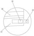
焊接机构包括焊枪11,两个活动架40的内部均设置有转动槽12,且两个转动槽12的内部均活动设置有转动架13,位于后侧的转动架13一侧设置有连接块14,且连接块14的一侧设置有第一伺服电缸15,第一伺服电缸15的驱动端设置有焊枪11,位于后侧的活动架40内部转动设置有驱动齿轮16,且转动架13的一侧设置有与驱动齿轮16相配合的齿牙,驱动齿轮16的表面与齿牙的表面啮合传动,其中驱动齿轮16通过电机驱动,在对压力管道的坡口进行焊接处理时,通过驱动齿轮16带动转动架13在转动槽12的内部进行转动,利用第一伺服电缸15的驱动端带动焊枪11与压力管道的坡口处靠近,利用焊枪11对压力管道的坡口处进行焊接处理,利用转动架13带动焊枪11对压力管道的坡口实现自动焊接,显著提高了对压力管道的焊接效率。The welding mechanism includes a welding torch 11, and the inside of the two movable frames 40 is provided with a rotating groove 12, and the inside of the two rotating grooves 12 is provided with a rotating frame 13, and the rotating frame 13 side on the rear side is provided with a connecting block 14 , and one side of the connection block 14 is provided with a first servo electric cylinder 15, the driving end of the first servo electric cylinder 15 is provided with a welding torch 11, and the movable frame 40 at the rear side is provided with a drive gear 16 for rotation, and the turret 13 One side of the drive gear 16 is provided with teeth that match the surface of the drive gear 16 and the surface of the teeth is engaged for transmission, wherein the drive gear 16 is driven by a motor, and when the groove of the pressure pipe is welded, it is driven The gear 16 drives the turret 13 to rotate inside the rotating groove 12, and the driving end of the first servo electric cylinder 15 drives the welding torch 11 to approach the bevel of the pressure pipe, and uses the welding torch 11 to perform welding on the bevel of the pressure pipe , using the turret 13 to drive the welding torch 11 to realize automatic welding of the bevel of the pressure pipe, which significantly improves the welding efficiency of the pressure pipe.
进一步的,转动架13的顶部与底部分别设置有第一卡块17与第二卡块18,且第二卡块18的内部设置有与第一卡块17相配合的卡槽19,活动架40内部的上下方均设置有电动推杆110,且两个电动推杆110的驱动端均设置有磁贴,利用磁贴对第一卡块17与第二卡块18的一侧进行吸引,其中第一卡块17的一端垂直插入转动架13的内部,第二卡块18位于转动架13的内部横向运动,两个转动架13内部的第一卡块17与第二卡块18位置相反,在控制两个活动架40相互接触后,首先通过控制前侧转动架13内部的第二卡块18的一端插入后侧转动架13的内部,接着控制后侧转动架13内部的第一卡块17插入第二卡块18内部的卡槽19中,利用第一卡块17和第二卡块18在后侧转动架13内部的配合连接,实现对两个转动架13的配合连接,利用驱动齿轮16与转动架13一侧的齿牙啮合传动,让两个转动架13在两个转动槽12的内部进行转动,从而让焊枪11对压力管道的坡口进行自动焊接。Further, the top and the bottom of the
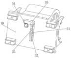
消磁组件包括金属条21,活动架40的内部设置有若干个第二伺服电缸22,且若干个第二伺服电缸22关于焊接机构对称设置,若干个第二伺服电缸22的驱动端均设置有金属条21,且焊接机构两侧的金属条21一端相互连接,在对压力管道进行焊接处理之前,对压力管道的磁性进行检测,对于磁性超标不是很大的,通过第二伺服电缸22的驱动端推动金属条21与压力管道的表面接触,让压力管道坡口区的两侧连接,使压力管道坡口区由原来的磁极端变磁体区,减少了坡口区的磁性,从而实现压力管道坡口区的焊接,显著提高对压力管道的焊接效率,并且能够有效保证压力管道的焊接质量。The degaussing assembly includes metal strips 21, and the inside of the
进一步的,活动架40内壁的两侧均设置有螺旋槽23,且螺旋槽23内壁的一侧设置有齿条24,螺旋槽23的内部活动设置有电动滑块25,且电动滑块25的底部与齿条24的表面啮合传动,电动滑块25的一侧设置有电焊把线26,且电焊把线26的另一端设置有放线架,其中放线架位于活动架40的内部设置,利用放线架对电焊把线26进行收线和放线;螺旋槽23的一端设置有连接片27,位于焊接机构两侧的连接片27电性连接,在利用电动滑块25带动电焊把线26运动至螺旋槽23的一侧后,让电焊把线26的一端与连接片27接触,从而让活动架40内部两侧的电焊把线26电性连接,在对压力管道进行消磁处理时,通过电动滑块25带动电焊把线26沿着螺旋槽23运动,让电焊把线26缠绕在压力管道的表面,接着通过向电焊把线26的内部通入直流电,产生磁性,调整电流大小和方向,抵消压力管道本体的磁性,再配合焊接机构对压力管道进行焊接处理,无需人工进行电焊把线26的缠绕,有效提高对压力管道的焊接效率。Further, both sides of movable frame 40 inner wall are provided with helical groove 23, and one side of helical groove 23 inner wall is provided with rack 24, and the internal activity of helical groove 23 is provided with electric slide block 25, and electric slide block 25 The bottom is meshed with the surface of the rack 24 for transmission, one side of the electric slider 25 is provided with a welding handle 26, and the other end of the welding handle 26 is provided with a pay-off rack, wherein the pay-off rack is arranged inside the movable frame 40, Utilize the pay-off rack to take up and pay off the electric welding handle wire 26; one end of the spiral groove 23 is provided with a connecting piece 27, and the connecting piece 27 located on both sides of the welding mechanism is electrically connected, and the electric welding handle is driven by the electric slider 25 26 after moving to one side of the spiral groove 23, let one end of the electric welding wire 26 contact the connecting piece 27, thereby allowing the electric welding wire 26 on both sides inside the movable frame 40 to be electrically connected, when the pressure pipeline is demagnetized, The electric slider 25 drives the electric welding wire 26 to move along the spiral groove 23, so that the electric welding wire 26 is wound on the surface of the pressure pipe, and then a direct current is passed into the inside of the electric welding wire 26 to generate magnetism and adjust the magnitude and direction of the current , Offset the magnetism of the pressure pipe body, and then cooperate with the welding mechanism to weld the pressure pipe, without manual winding of the welding wire 26, effectively improving the welding efficiency of the pressure pipe.
进一步的,对于压力管道的消磁方式还可以采用氧气/乙炔割枪对坡口两侧进行加热,火焰调节为中性焰,温度达到900℃-1200℃,合金中的相结构由带磁的铁素体+珠光体转变为无磁性的奥氏体,颜色为亮红色,接着对加热区马上进行打底焊接,焊接参数可选用平时的焊接参数,采用连续打底法,增加焊接区温度,减缓加热区温度降低速度,当加热区由亮红色变为暗红色时,焊接声音改变,熔池熔敷金属无法融合,要马上停止焊接,重新加热。Further, for the degaussing method of the pressure pipeline, an oxygen/acetylene torch can be used to heat both sides of the groove, the flame is adjusted to a neutral flame, and the temperature reaches 900°C-1200°C. The phase structure in the alloy is composed of magnetic iron The ferrite + pearlite transforms into non-magnetic austenite, the color is bright red, and then the heating zone is immediately grounded and welded. The welding parameters can be selected from the usual welding parameters. The continuous grounding method is used to increase the temperature of the welding zone and slow down The temperature of the heating zone decreases quickly. When the heating zone changes from bright red to dark red, the welding sound changes, and the deposited metal in the molten pool cannot be fused. Stop welding immediately and reheat.
根据钢管直径加热焊接6-12处,由原来磁性最强的两端转变为连接后的中段,磁性得到弱化,剩余磁性经6-12段的打底焊接处通过,未打底处的磁性可以达到标准小于0.3mT(240A/m)的要求,可以正常焊接。According to the diameter of the steel pipe, it is heated and welded at 6-12 places, and the two ends with the strongest magnetism are transformed into the middle section after the connection. The magnetism is weakened, and the residual magnetism passes through the bottom welding part of the 6-12 section. It meets the standard requirement of less than 0.3mT (240A/m), and can be welded normally.
对于要求较高,有相应无损检测要求的焊缝,可以双面焊的,在完成外圈的焊接后,到管内清除打底层,再进行封底焊,对于只能单面焊的,完成6-12段打底后,根据焊接情况进行处理,其他处能正常焊接的,先进行其他处的打底、填充、盖面焊接,然后再将6-12处的打底处逐一清除后重新进行打底、填充、盖面的焊接;如磁性仍较强,其他处仍无法正常的焊接的应先将6-12的打底处,进行填充或填充+盖面的焊接,也增加磁通量,使其他处能够正常焊接,待其他处正常焊接完成后,再将6-12处的焊缝逐一重新焊接。For welding seams with high requirements and corresponding non-destructive testing requirements, double-sided welding can be performed. After the outer ring is welded, the bottom layer should be removed in the pipe, and then the bottom sealing welding should be performed. For welding seams that can only be welded on one side, complete 6- After the 12-stage primer, handle it according to the welding situation. If other places can be welded normally, first perform the primer, filling, and cover welding of other places, and then remove the primers at positions 6-12 one by one and re-peel Welding of the bottom, filling, and cover; if the magnetism is still strong, and other parts still cannot be welded normally, the bottom part of 6-12 should be filled or filled + cover welded, and the magnetic flux will also be increased to make other parts It can be welded normally, and after the normal welding of other places is completed, the welds at 6-12 are re-welded one by one.
进一步的,活动底架10的内部设置有滑槽31,且滑槽31的内部转动设置有螺纹杆32,其中螺纹杆32表面的两侧设置有旋向相反的外螺纹;滑槽31的内部滑动设置有两个活动块33,且两个活动块33的顶部分别与两个活动板30的底部连接,两个活动块33的内部均设置有螺纹孔,且两个螺纹孔的内部均与螺纹杆32的表面螺纹连接,活动底架10的底部设置有伺服电机34,且伺服电机34的一侧设置有驱动块35,其中驱动块35的内部设置有两个相互啮合的传动齿轮,其中一个传动齿轮的内部与伺服电机34的输出端连接,另一个传动齿轮的内部与螺纹杆32的一端连接。Further, the inside of the
需要说明的是,利用伺服电机34和驱动块35配合驱动螺纹杆32进行顺时针转动,让两个活动块33在滑槽31的内部沿着螺纹杆32做相反方向的运动,利用两个活动块33带动两个活动板30在活动底架10的顶部进行相反方向运动,让两个活动架40相互远离,从而便于对压力管道进行消磁和焊接处理。It should be noted that the threaded
同时本说明书中未作详细描述的内容均属于本领域技术人员公知的现有技术。At the same time, the content not described in detail in this specification belongs to the prior art known to those skilled in the art.
需要说明的是,在本文中,诸如第一和第二等之类的关系术语仅仅用来将一个实体或者操作与另一个实体或操作区分开来,而不一定要求或者暗示这些实体或操作之间存在任何这种实际的关系或者顺序。而且,术语“包括”、“包含”或者其任何其他变体意在涵盖非排他性的包含,从而使得包括一系列要素的过程、方法、物品或者设备不仅包括那些要素,而且还包括没有明确列出的其他要素,或者是还包括为这种过程、方法、物品或者设备所固有的要素。It should be noted that in this article, relational terms such as first and second are only used to distinguish one entity or operation from another entity or operation, and do not necessarily require or imply that there is a relationship between these entities or operations. There is no such actual relationship or order between them. Furthermore, the term "comprises", "comprises" or any other variation thereof is intended to cover a non-exclusive inclusion such that a process, method, article, or apparatus comprising a set of elements includes not only those elements, but also includes elements not expressly listed. other elements of or also include elements inherent in such a process, method, article, or device.
尽管已经示出和描述了本发明的实施例,对于本领域的普通技术人员而言,可以理解在不脱离本发明的原理和精神的情况下可以对这些实施例进行多种变化、修改、替换和变型,本发明的范围由所附权利要求及其等同物限定。Although the embodiments of the present invention have been shown and described, those skilled in the art can understand that various changes, modifications and substitutions can be made to these embodiments without departing from the principle and spirit of the present invention. and modifications, the scope of the invention is defined by the appended claims and their equivalents.
Claims (8)
Priority Applications (1)
| Application Number | Priority Date | Filing Date | Title |
|---|---|---|---|
| CN202310301898.5ACN116174849B (en) | 2023-03-27 | 2023-03-27 | Pressure pipeline magnetic installation welding process and equipment thereof |
Applications Claiming Priority (1)
| Application Number | Priority Date | Filing Date | Title |
|---|---|---|---|
| CN202310301898.5ACN116174849B (en) | 2023-03-27 | 2023-03-27 | Pressure pipeline magnetic installation welding process and equipment thereof |
Publications (2)
| Publication Number | Publication Date |
|---|---|
| CN116174849Atrue CN116174849A (en) | 2023-05-30 |
| CN116174849B CN116174849B (en) | 2025-07-29 |
Family
ID=86432915
Family Applications (1)
| Application Number | Title | Priority Date | Filing Date |
|---|---|---|---|
| CN202310301898.5AActiveCN116174849B (en) | 2023-03-27 | 2023-03-27 | Pressure pipeline magnetic installation welding process and equipment thereof |
Country Status (1)
| Country | Link |
|---|---|
| CN (1) | CN116174849B (en) |
Citations (10)
| Publication number | Priority date | Publication date | Assignee | Title |
|---|---|---|---|---|
| JPH0683164U (en)* | 1993-04-21 | 1994-11-29 | 石川島播磨重工業株式会社 | Demagnetization device in the groove |
| CN102019492A (en)* | 2010-11-18 | 2011-04-20 | 中国石化集团第十建设公司 | Demagnetizing and deflective blow preventing device of pipeline welding line |
| CN103506780A (en)* | 2012-08-31 | 2014-01-15 | 中国有色金属工业第六冶金建设有限公司 | Magnetized steel tube welding process |
| CN105312728A (en)* | 2014-06-09 | 2016-02-10 | 山东电力建设第一工程公司 | Device for eliminating influence of continuous high-intensity magnetic field on welding operation |
| CN107414353A (en)* | 2017-07-28 | 2017-12-01 | 无锡康柏斯机械科技有限公司 | A kind of demagnetization welding method for the pipeline that is magnetized |
| CN110911086A (en)* | 2019-06-20 | 2020-03-24 | 北京能嘉科技有限公司 | Pipeline demagnetizing method, device and system in oil-gas pipeline welding operation |
| CN111341521A (en)* | 2020-04-01 | 2020-06-26 | 西安石油大学 | Coil structure and application for on-line elimination of residual magnetism in ferromagnetic pipelines |
| CN112248454A (en)* | 2020-10-23 | 2021-01-22 | 刘倩 | Special welding equipment and method for antifreeze nylon pipe fittings for offshore platforms |
| CN215747006U (en)* | 2021-09-06 | 2022-02-08 | 宋满堂 | Flexible detachable magnetic conductive device |
| CN114850739A (en)* | 2022-04-28 | 2022-08-05 | 易磊 | Welding device for wind power generation tower cylinder |
- 2023
- 2023-03-27CNCN202310301898.5Apatent/CN116174849B/enactiveActive
Patent Citations (10)
| Publication number | Priority date | Publication date | Assignee | Title |
|---|---|---|---|---|
| JPH0683164U (en)* | 1993-04-21 | 1994-11-29 | 石川島播磨重工業株式会社 | Demagnetization device in the groove |
| CN102019492A (en)* | 2010-11-18 | 2011-04-20 | 中国石化集团第十建设公司 | Demagnetizing and deflective blow preventing device of pipeline welding line |
| CN103506780A (en)* | 2012-08-31 | 2014-01-15 | 中国有色金属工业第六冶金建设有限公司 | Magnetized steel tube welding process |
| CN105312728A (en)* | 2014-06-09 | 2016-02-10 | 山东电力建设第一工程公司 | Device for eliminating influence of continuous high-intensity magnetic field on welding operation |
| CN107414353A (en)* | 2017-07-28 | 2017-12-01 | 无锡康柏斯机械科技有限公司 | A kind of demagnetization welding method for the pipeline that is magnetized |
| CN110911086A (en)* | 2019-06-20 | 2020-03-24 | 北京能嘉科技有限公司 | Pipeline demagnetizing method, device and system in oil-gas pipeline welding operation |
| CN111341521A (en)* | 2020-04-01 | 2020-06-26 | 西安石油大学 | Coil structure and application for on-line elimination of residual magnetism in ferromagnetic pipelines |
| CN112248454A (en)* | 2020-10-23 | 2021-01-22 | 刘倩 | Special welding equipment and method for antifreeze nylon pipe fittings for offshore platforms |
| CN215747006U (en)* | 2021-09-06 | 2022-02-08 | 宋满堂 | Flexible detachable magnetic conductive device |
| CN114850739A (en)* | 2022-04-28 | 2022-08-05 | 易磊 | Welding device for wind power generation tower cylinder |
Also Published As
| Publication number | Publication date |
|---|---|
| CN116174849B (en) | 2025-07-29 |
Similar Documents
| Publication | Publication Date | Title |
|---|---|---|
| US11084118B2 (en) | Method and system of all-position plasma welding process for titanium alloy pipeline | |
| CN103264209A (en) | Combine-welding method of stainless steel welded parts | |
| CN103567652A (en) | Aluminum alloy direct current plasma-tungsten electrode argon arc hybrid welding method based on pulse coordination control | |
| CN202240097U (en) | A kind of vacuum argon shielded welding equipment | |
| CN109396607B (en) | Inversion multifunctional welding machine | |
| CN116174849A (en) | A pressure pipeline magnetic installation welding process and its equipment | |
| CN211759106U (en) | Argon arc welding device for double-side butt welding | |
| CN111618390A (en) | Lug soldering equipment for driving motor production line | |
| CN117260293A (en) | Electromagnetic induction brazing process and device for manufacturing coiled welded pipe by layered composite metal strip | |
| CN204487019U (en) | Double automatic soldering device | |
| CN112059375A (en) | Self-adaptive double-sided water-cooling electrogas welding equipment and method for reducing welding slag | |
| WO2010118625A1 (en) | Sealing device for straight edge end of multilayer thin-walled corrugated pipe | |
| US3062950A (en) | Arc spot welding method and apparatus | |
| CN210413189U (en) | Automatic pipe welding equipment | |
| CN110560820A (en) | Flexible automatic welding gun | |
| CN205520020U (en) | Two -sided shaping welding set of one side welding with back of body protection gas | |
| CN215768381U (en) | Fluorescent magnetic powder flaw detector special for round flat pin | |
| CN210147206U (en) | Portable pipeline welding robot | |
| CN107813035A (en) | A kind of anti-ozone-type dividing plate narrow gap welding device | |
| CN204277178U (en) | A kind of multi-functional welding head | |
| CN2785777Y (en) | Continuous bright brazing unit for composite steel pipe | |
| CN209716753U (en) | A kind of numerical control induction welding equipment | |
| CN107335897A (en) | Novel pipeline all-position automatic welding technology equipment | |
| JP2604696B2 (en) | Welding method for stainless steel pipes | |
| CN223235421U (en) | Fine welding device for composite nitrogen alloy cored wire |
Legal Events
| Date | Code | Title | Description |
|---|---|---|---|
| PB01 | Publication | ||
| PB01 | Publication | ||
| SE01 | Entry into force of request for substantive examination | ||
| SE01 | Entry into force of request for substantive examination | ||
| GR01 | Patent grant | ||
| GR01 | Patent grant |