CN116172750A - Delivery Devices and Valve Clamping Systems - Google Patents
Delivery Devices and Valve Clamping SystemsDownload PDFInfo
- Publication number
- CN116172750A CN116172750ACN202111426544.0ACN202111426544ACN116172750ACN 116172750 ACN116172750 ACN 116172750ACN 202111426544 ACN202111426544 ACN 202111426544ACN 116172750 ACN116172750 ACN 116172750A
- Authority
- CN
- China
- Prior art keywords
- control
- insertion rod
- pipe
- hollow tube
- rod
- Prior art date
- Legal status (The legal status is an assumption and is not a legal conclusion. Google has not performed a legal analysis and makes no representation as to the accuracy of the status listed.)
- Pending
Links
Images


Classifications
- A—HUMAN NECESSITIES
- A61—MEDICAL OR VETERINARY SCIENCE; HYGIENE
- A61F—FILTERS IMPLANTABLE INTO BLOOD VESSELS; PROSTHESES; DEVICES PROVIDING PATENCY TO, OR PREVENTING COLLAPSING OF, TUBULAR STRUCTURES OF THE BODY, e.g. STENTS; ORTHOPAEDIC, NURSING OR CONTRACEPTIVE DEVICES; FOMENTATION; TREATMENT OR PROTECTION OF EYES OR EARS; BANDAGES, DRESSINGS OR ABSORBENT PADS; FIRST-AID KITS
- A61F2/00—Filters implantable into blood vessels; Prostheses, i.e. artificial substitutes or replacements for parts of the body; Appliances for connecting them with the body; Devices providing patency to, or preventing collapsing of, tubular structures of the body, e.g. stents
- A61F2/02—Prostheses implantable into the body
- A61F2/24—Heart valves ; Vascular valves, e.g. venous valves; Heart implants, e.g. passive devices for improving the function of the native valve or the heart muscle; Transmyocardial revascularisation [TMR] devices; Valves implantable in the body
- A61F2/2409—Support rings therefor, e.g. for connecting valves to tissue
- A—HUMAN NECESSITIES
- A61—MEDICAL OR VETERINARY SCIENCE; HYGIENE
- A61F—FILTERS IMPLANTABLE INTO BLOOD VESSELS; PROSTHESES; DEVICES PROVIDING PATENCY TO, OR PREVENTING COLLAPSING OF, TUBULAR STRUCTURES OF THE BODY, e.g. STENTS; ORTHOPAEDIC, NURSING OR CONTRACEPTIVE DEVICES; FOMENTATION; TREATMENT OR PROTECTION OF EYES OR EARS; BANDAGES, DRESSINGS OR ABSORBENT PADS; FIRST-AID KITS
- A61F2/00—Filters implantable into blood vessels; Prostheses, i.e. artificial substitutes or replacements for parts of the body; Appliances for connecting them with the body; Devices providing patency to, or preventing collapsing of, tubular structures of the body, e.g. stents
- A61F2/02—Prostheses implantable into the body
- A61F2/24—Heart valves ; Vascular valves, e.g. venous valves; Heart implants, e.g. passive devices for improving the function of the native valve or the heart muscle; Transmyocardial revascularisation [TMR] devices; Valves implantable in the body
- A61F2/2427—Devices for manipulating or deploying heart valves during implantation
- A—HUMAN NECESSITIES
- A61—MEDICAL OR VETERINARY SCIENCE; HYGIENE
- A61F—FILTERS IMPLANTABLE INTO BLOOD VESSELS; PROSTHESES; DEVICES PROVIDING PATENCY TO, OR PREVENTING COLLAPSING OF, TUBULAR STRUCTURES OF THE BODY, e.g. STENTS; ORTHOPAEDIC, NURSING OR CONTRACEPTIVE DEVICES; FOMENTATION; TREATMENT OR PROTECTION OF EYES OR EARS; BANDAGES, DRESSINGS OR ABSORBENT PADS; FIRST-AID KITS
- A61F2/00—Filters implantable into blood vessels; Prostheses, i.e. artificial substitutes or replacements for parts of the body; Appliances for connecting them with the body; Devices providing patency to, or preventing collapsing of, tubular structures of the body, e.g. stents
- A61F2/02—Prostheses implantable into the body
- A61F2/24—Heart valves ; Vascular valves, e.g. venous valves; Heart implants, e.g. passive devices for improving the function of the native valve or the heart muscle; Transmyocardial revascularisation [TMR] devices; Valves implantable in the body
- A61F2/2442—Annuloplasty rings or inserts for correcting the valve shape; Implants for improving the function of a native heart valve
- A61F2/2445—Annuloplasty rings in direct contact with the valve annulus
- A—HUMAN NECESSITIES
- A61—MEDICAL OR VETERINARY SCIENCE; HYGIENE
- A61F—FILTERS IMPLANTABLE INTO BLOOD VESSELS; PROSTHESES; DEVICES PROVIDING PATENCY TO, OR PREVENTING COLLAPSING OF, TUBULAR STRUCTURES OF THE BODY, e.g. STENTS; ORTHOPAEDIC, NURSING OR CONTRACEPTIVE DEVICES; FOMENTATION; TREATMENT OR PROTECTION OF EYES OR EARS; BANDAGES, DRESSINGS OR ABSORBENT PADS; FIRST-AID KITS
- A61F2/00—Filters implantable into blood vessels; Prostheses, i.e. artificial substitutes or replacements for parts of the body; Appliances for connecting them with the body; Devices providing patency to, or preventing collapsing of, tubular structures of the body, e.g. stents
- A61F2/02—Prostheses implantable into the body
- A61F2/24—Heart valves ; Vascular valves, e.g. venous valves; Heart implants, e.g. passive devices for improving the function of the native valve or the heart muscle; Transmyocardial revascularisation [TMR] devices; Valves implantable in the body
- A61F2/2442—Annuloplasty rings or inserts for correcting the valve shape; Implants for improving the function of a native heart valve
- A61F2/246—Devices for obstructing a leak through a native valve in a closed condition
- A—HUMAN NECESSITIES
- A61—MEDICAL OR VETERINARY SCIENCE; HYGIENE
- A61F—FILTERS IMPLANTABLE INTO BLOOD VESSELS; PROSTHESES; DEVICES PROVIDING PATENCY TO, OR PREVENTING COLLAPSING OF, TUBULAR STRUCTURES OF THE BODY, e.g. STENTS; ORTHOPAEDIC, NURSING OR CONTRACEPTIVE DEVICES; FOMENTATION; TREATMENT OR PROTECTION OF EYES OR EARS; BANDAGES, DRESSINGS OR ABSORBENT PADS; FIRST-AID KITS
- A61F2/00—Filters implantable into blood vessels; Prostheses, i.e. artificial substitutes or replacements for parts of the body; Appliances for connecting them with the body; Devices providing patency to, or preventing collapsing of, tubular structures of the body, e.g. stents
- A61F2/02—Prostheses implantable into the body
- A61F2/24—Heart valves ; Vascular valves, e.g. venous valves; Heart implants, e.g. passive devices for improving the function of the native valve or the heart muscle; Transmyocardial revascularisation [TMR] devices; Valves implantable in the body
- A61F2/2442—Annuloplasty rings or inserts for correcting the valve shape; Implants for improving the function of a native heart valve
- A61F2/2466—Delivery devices therefor
Landscapes
- Health & Medical Sciences (AREA)
- Cardiology (AREA)
- Engineering & Computer Science (AREA)
- Biomedical Technology (AREA)
- Heart & Thoracic Surgery (AREA)
- Transplantation (AREA)
- Oral & Maxillofacial Surgery (AREA)
- Vascular Medicine (AREA)
- Life Sciences & Earth Sciences (AREA)
- Animal Behavior & Ethology (AREA)
- General Health & Medical Sciences (AREA)
- Public Health (AREA)
- Veterinary Medicine (AREA)
- Infusion, Injection, And Reservoir Apparatuses (AREA)
Abstract
Description
Translated fromChinese技术领域technical field
本发明涉及医疗器械技术领域,尤其涉及一种输送装置及瓣膜夹合系统。The invention relates to the technical field of medical devices, in particular to a delivery device and a valve clipping system.
背景技术Background technique
二尖瓣关闭不全是当今最常见的瓣膜病变之一,主要原因有二尖瓣环扩张、腱索功能不全、二尖瓣粘液变性、瓣叶脱垂、风湿性心瓣膜病、缺血性病变等。二尖瓣直视成形术及人工瓣膜置换术是治疗二尖瓣关闭不全的最有效方法,但是由于手术需要体外循环技术支持,给人体带来的创伤比较大,对高龄患者和有较多合并症患者,有相当高的并发症和死亡率。Mitral valve insufficiency is one of the most common valvular diseases today, the main reasons are mitral valve ring dilatation, chordal insufficiency, mitral valve mucus degeneration, valve leaflet prolapse, rheumatic heart valve disease, ischemic disease wait. Direct mitral valvuloplasty and artificial valve replacement are the most effective methods for the treatment of mitral valve insufficiency, but because the operation requires extracorporeal circulation technical support, the trauma to the human body is relatively large, and there are many complications for elderly patients. disease patients, there are quite high morbidity and mortality.
近年各国的医务人员和科研人员进行了经导管二尖瓣修复技术的探索,主要的介入治疗方式有瓣环成形术、负压抽吸缝合技术及二尖瓣钳夹术等,其中以二尖瓣钳夹术疗效最为可靠。二尖瓣钳夹术通过房间隔穿刺将一个可植入的瓣膜夹合器送至二尖瓣附近,将前后瓣叶的游离缘进行钳夹固定,使瓣叶在收缩末期对合良好,减少返流。传统瓣膜夹合系统通过丝线控制夹片的开合,丝线具备较好的柔顺性,利用丝线易于调节夹片的开合角度。然而,丝线使用过程中,存在较大的断裂风险,可靠性低,并且夹合完成后,不易从夹片上拆除。In recent years, medical personnel and researchers from various countries have explored transcatheter mitral valve repair techniques. The main interventional methods include annuloplasty, negative pressure suction suture technique, and mitral valve clamping. The curative effect of valve forceps is the most reliable. Mitral valve clipping sends an implantable valve clamp to the vicinity of the mitral valve through atrial septal puncture, and clamps and fixes the free edges of the anterior and posterior valve leaflets, so that the valve leaflets can fit well at the end of systole, reducing Reflux. The traditional valve clamping system controls the opening and closing of the clips through silk threads. The silk threads have good flexibility, and the opening and closing angle of the clips can be easily adjusted by using the silk threads. However, during the use of the silk thread, there is a greater risk of breaking, and the reliability is low, and it is not easy to remove from the clip after the clip is completed.
发明内容Contents of the invention
本发明的目的在于提供一种输送装置及瓣膜夹合系统,能够解决现有瓣膜修复手术中,输送装置容易断裂、拆装不便的技术问题。The purpose of the present invention is to provide a delivery device and a valve clamping system, which can solve the technical problems that the delivery device is easy to break and inconvenient to disassemble in the existing valve repair operation.
第一方面,本发明提供了一种输送装置及瓣膜夹合系统,用于输送瓣膜夹合器,所述瓣膜夹合器包括固定座及近端夹片,所述近端夹片设置于所述固定座上且可相对于所述固定座收拢或展开,所述输送装置包括:In the first aspect, the present invention provides a delivery device and a valve clamping system for delivering a valve clamp. The valve clamp includes a fixing seat and a proximal clip, and the proximal clip is arranged on the on the fixed seat and can be folded or unfolded relative to the fixed seat, the delivery device includes:
输送鞘管,包括连接端及操控端;Delivery sheath, including connection end and control end;
操控件,包括控制杆、操控手柄及连接头,所述控制杆活动地穿设于所述输送鞘管内,且所述控制杆包括空心管及活动地穿设于所述空心管内的插杆;所述操控手柄连接于所述空心管及所述插杆的一端且由所述输送鞘管的操控端伸出;所述连接头可拆卸地连接于所述空心管的另一端,所述连接头用于连接所述近端夹片;所述操控手柄用于带动所述空心管与所述插杆活动,以使所述连接头与所述空心管连接或断开,以及,使所述近端夹片相对于所述固定座收拢或展开。The control member includes a control rod, a control handle and a connector, the control rod is movably threaded in the delivery sheath, and the control rod includes a hollow tube and an insertion rod movably threaded in the hollow tube; The control handle is connected to the hollow tube and one end of the insertion rod and protrudes from the control end of the delivery sheath; the connector is detachably connected to the other end of the hollow tube, and the connection The head is used to connect the proximal clip; the control handle is used to drive the hollow tube and the insertion rod to move, so that the connecting head is connected to or disconnected from the hollow tube, and the The proximal clip is folded or unfolded relative to the fixing seat.
在一实施例中,所述连接头包括第一连接部,所述控制杆包括第二连接部,所述操控手柄用于带动所述插杆在所述第一连接部及所述第二连接部内移动,以使所述空心管与所述连接头连接或断开。In one embodiment, the connecting head includes a first connecting portion, the control lever includes a second connecting portion, and the control handle is used to drive the insertion rod between the first connecting portion and the second connecting portion. The inner part moves to connect or disconnect the hollow tube with the connecting head.
在一实施例中,所述第一连接部为内部中空的连接管头,所述第二连接部为设置于所述空心管连接于所述连接头一端的弹性臂,所述弹性臂可伸入所述连接管头内并与所述连接管头相卡持;In one embodiment, the first connecting part is a hollow connecting pipe head, and the second connecting part is an elastic arm provided at one end of the hollow pipe connected to the connecting head, and the elastic arm can extend into the connecting pipe head and clamped with the connecting pipe head;
所述操控手柄用于控制所述插杆沿所述空心管的轴向移动,以使所述插杆在锁定状态及切换状态之间切换,其中,所述插杆处于锁定状态时,所述弹性臂在所述插杆的抵持下与所述连接管头相卡持;所述插杆处于解锁状态时,所述插杆远离所述弹性臂,所述弹性臂与所述连接管头可沿所述插杆的轴向分离。The control handle is used to control the axial movement of the insertion rod along the hollow tube, so that the insertion rod can be switched between the locked state and the switching state, wherein, when the insertion rod is in the locked state, the The elastic arm is clamped with the connecting pipe head under the resistance of the insertion rod; when the insertion rod is in the unlocked state, the insertion rod is away from the elastic arm, and the elastic arm and the connecting pipe head It can be detached along the axial direction of the plunger.
在一实施例中,所述弹性臂包括两个相对设置的弹片,沿指向所述弹片的自由端的方向,两个所述弹片呈渐缩结构;In one embodiment, the elastic arm includes two opposite elastic pieces, and the two elastic pieces are in a tapered structure along the direction to the free ends of the elastic pieces;
所述插杆可伸入两个所述弹片之间并抵接于所述弹片内壁上,以使所述弹片与所述连接管头的内壁抵接。The insertion rod can extend between the two elastic pieces and abut against the inner wall of the elastic piece, so that the elastic piece abuts against the inner wall of the connecting pipe head.
在一实施例中,所述连接管头的内壁上设有第一卡接结构,所述弹片的外壁上设有与所述第一卡接结构配合卡接的第二卡接结构。In one embodiment, the inner wall of the connecting pipe head is provided with a first snapping structure, and the outer wall of the elastic sheet is provided with a second snapping structure that cooperates with the first snapping structure.
在一实施例中,所述第一连接部为第一半管,所述第二连接部为第二半管,所述第一半管及所述第二半管的边缘处分别形成有可配合卡接的限位槽及限位凸缘,所述第一半管及所述第二半管对合后形成中空管结构,且所述限位槽与所述限位凸缘沿所述中空管的轴向相卡持;In one embodiment, the first connecting part is a first half pipe, the second connecting part is a second half pipe, and the edges of the first half pipe and the second half pipe are respectively formed with possible Cooperate with the clamping limit groove and limit flange, the first half pipe and the second half pipe are combined to form a hollow pipe structure, and the limit groove and the limit flange are aligned along the The axial phase clamping of the hollow tube;
所述操控手柄用于控制所述插杆沿所述空心管的轴向移动,以使所述插杆在锁定状态及切换状态间切换,其中,所述插杆处于锁定状态时,所述插杆伸入所述第一半管与所述第二半管对合形成的所述中空管内,所述第一半管与所述第二半管沿所述插杆的径向被锁定;所述插杆处于解锁状态时,所述插杆远离所述第一半管和所述第二半管,所述第一半管与所述第二半管可沿所述插杆的径向分离。The control handle is used to control the axial movement of the insertion rod along the hollow tube, so that the insertion rod can be switched between the locked state and the switching state, wherein, when the insertion rod is in the locked state, the insertion rod The rod extends into the hollow pipe formed by the combination of the first half pipe and the second half pipe, and the first half pipe and the second half pipe are locked along the radial direction of the insertion rod; When the insertion rod is in the unlocked state, the insertion rod is away from the first half pipe and the second half pipe, and the first half pipe and the second half pipe can be separated along the radial direction of the insertion rod .
在一实施例中,所述第一半管及所述第二半管的边缘处为圆滑过渡的S形结构。In one embodiment, the edges of the first half pipe and the second half pipe are S-shaped structures with a smooth transition.
在一实施例中,所述连接头包括用于连接所述近端夹片的固定环。In one embodiment, the connector includes a retaining ring for connecting the proximal clip.
在一实施例中,所述输送装置包括两组所述操控件,所述输送鞘管包括两组沿其轴向延伸且中心对称的输送腔,两组所述操控件分别活动地设置于两组所述输送腔内。In one embodiment, the delivery device includes two sets of manipulators, the delivery sheath includes two sets of delivery lumens that extend along its axial direction and are center-symmetrical, and the two sets of manipulators are respectively movably arranged on the two sides. group described in the delivery chamber.
本发明提供的输送装置,包括输送鞘管及操控件,操控件包括操控手柄、连接于瓣膜夹合器近端夹片的连接头以及用于连接操控手柄及连接头的控制杆,通过控制操控手柄,可带动控制杆及连接头移动,进而能够带动连接于连接头的近端夹片相对于固定座收拢或展开,实现瓣膜夹合器的输送及固定。其中,控制杆设置于输送鞘管内,可以免受人体组织的挤压,利用操控手柄带动控制杆移动时,摩擦阻力小,控制杆移动方便且不易损伤人体组织,此外,控制杆强度高,使用过程中不易断裂,可靠性高。进一步地,控制杆包括空心管及活动地穿设于空心管内的插杆,操控手柄连接于空心管及插杆的一端,连接头可拆卸地连接于空心管的另一端,瓣膜夹合器安装到位后,利用操控手柄带动空心管与插杆活动,可快速断开连接头与空心管的连接,从而能够直接断开输送鞘管、控制杆及操控手柄与瓣膜夹合器的连接,操作难度小且快速方便。采用上述输送装置输送并调节瓣膜夹合器,能够有效缩短手术时长、提高手术成功率。The delivery device provided by the present invention includes a delivery sheath and a manipulator. The manipulator includes a control handle, a connector connected to the proximal clip of the valve clamp, and a control rod for connecting the manipulator handle and the connector. The handle can drive the control rod and the connecting head to move, and then can drive the proximal clip connected to the connecting head to fold or expand relative to the fixing seat, so as to realize the delivery and fixation of the valve clamp. Wherein, the control rod is set in the delivery sheath, which can avoid the extrusion of human tissue. When the control rod is used to drive the control rod to move, the frictional resistance is small, the control rod is easy to move and is not easy to damage human tissue. In addition, the control rod has high strength and is easy to use. It is not easy to break during the process and has high reliability. Further, the control rod includes a hollow tube and an insertion rod movably inserted in the hollow tube, the control handle is connected to one end of the hollow tube and the insertion rod, the connector is detachably connected to the other end of the hollow tube, and the valve clamp is installed After in place, use the control handle to drive the hollow tube and the insertion rod to move, and quickly disconnect the connection between the connector and the hollow tube, so that the connection between the delivery sheath, control rod and control handle and the valve clamp can be directly disconnected, which is difficult to operate Small and fast and convenient. Using the above delivery device to deliver and adjust the valve clamp can effectively shorten the operation time and improve the success rate of the operation.
第二方面,本发明公开了一种瓣膜夹合系统,包括瓣膜夹合器及如第一方面中所述的输送装置。In a second aspect, the present invention discloses a valve clamping system, including a valve clamp and the delivery device as described in the first aspect.
本实施例提供的瓣膜夹合系统中,输送装置包括鞘管及操控件,操控件包括操控手柄、连接于瓣膜夹合器近端夹片的连接头以及用于连接操控手柄及连接头的控制杆,通过控制操控手柄,可带动控制杆及连接头移动,进而能够带动连接于连接头的近端夹片相对于固定座收拢或展开,实现瓣膜夹合器的输送及固定。其中,控制杆设置于输送鞘管内,可以免受人体组织的挤压,利用操控手柄带动控制杆移动时,摩擦阻力小,控制杆移动方便且不易损伤人体组织,此外,控制杆强度高,使用过程中不易断裂,可靠性高。进一步地,控制杆包括空心管及活动地穿设于空心管内的插杆,操控手柄连接于空心管及插杆的一端,连接头可拆卸地连接于空心管的另一端,瓣膜夹合器安装到位后,利用操控手柄带动空心管与插杆活动,可快速断开连接头与空心管的连接,从而能够直接断开输送鞘管、控制杆及操控手柄与瓣膜夹合器的连接,操作难度小且快速方便。采用上述输送装置输送并调节瓣膜夹合器,能够有效缩短手术时长、提高手术成功率。In the valve clamping system provided in this embodiment, the delivery device includes a sheath and a manipulator, and the manipulator includes a manipulation handle, a connector connected to the proximal clip of the valve clamp, and a control device for connecting the manipulation handle and the connector. The rod, by controlling the control handle, can drive the control rod and the connecting head to move, and then can drive the proximal clip connected to the connecting head to fold or expand relative to the fixing seat, so as to realize the delivery and fixation of the valve clamp. Wherein, the control rod is set in the delivery sheath, which can avoid the extrusion of human tissue. When the control rod is used to drive the control rod to move, the frictional resistance is small, the control rod is easy to move and is not easy to damage human tissue. In addition, the control rod has high strength and is easy to use. It is not easy to break during the process and has high reliability. Further, the control rod includes a hollow tube and an insertion rod movably inserted in the hollow tube, the control handle is connected to one end of the hollow tube and the insertion rod, the connector is detachably connected to the other end of the hollow tube, and the valve clamp is installed After in place, use the control handle to drive the hollow tube and the insertion rod to move, and quickly disconnect the connection between the connector and the hollow tube, so that the connection between the delivery sheath, control rod and control handle and the valve clamp can be directly disconnected, which is difficult to operate Small and fast and convenient. Using the above delivery device to deliver and adjust the valve clamp can effectively shorten the operation time and improve the success rate of the operation.
附图说明Description of drawings
为了更清楚地说明本发明实施例或现有技术中的技术方案,下面将对实施例或现有技术描述中所需要使用的附图作简单地介绍,显而易见地,下面描述中的附图仅仅是本发明的一些实施例,对于本领域普通技术人员来讲,在不付出创造性劳动的前提下,还可以根据这些附图获得其他的附图。In order to more clearly illustrate the technical solutions in the embodiments of the present invention or the prior art, the following will briefly introduce the drawings that need to be used in the description of the embodiments or the prior art. Obviously, the accompanying drawings in the following description are only These are some embodiments of the present invention. Those skilled in the art can also obtain other drawings based on these drawings without creative work.
图1为本发明实施例提供的瓣膜夹合系统的结构示意图;FIG. 1 is a schematic structural view of a valve clamping system provided by an embodiment of the present invention;
图2为本发明实施例一提供的输送装置及瓣膜夹合器的结构示意图;FIG. 2 is a schematic structural view of the delivery device and the valve clamp provided by
图3为图2中所示控制杆与连接头的结构示意图之一;Fig. 3 is one of the schematic diagrams of the structure of the control rod and the connector shown in Fig. 2;
图4为图2中所示控制杆与连接头的结构示意图之二;Fig. 4 is the second schematic diagram of the structure of the control rod and the connector shown in Fig. 2;
图5为图2中所示连接头与近端夹片的结构示意图;Fig. 5 is a schematic structural view of the connector and the proximal clip shown in Fig. 2;
图6为本发明实施例二提供的输送装置及瓣膜夹合器的结构示意图;Fig. 6 is a schematic structural view of the delivery device and the valve clamp provided by the second embodiment of the present invention;
图7为图6中所示控制杆与连接头的结构示意图之一;Fig. 7 is one of the structural schematic diagrams of the control rod and the connector shown in Fig. 6;
图8为图6中所示控制杆与连接头的结构示意图之二;Fig. 8 is the second structural schematic diagram of the control rod and the connector shown in Fig. 6;
图9为图6中所示连接头与近端夹片的结构示意图;Fig. 9 is a schematic structural view of the connector and the proximal clip shown in Fig. 6;
图10为本发明实施例提供的一种瓣膜夹合器的近端夹片及固定座的结构示意图;Fig. 10 is a schematic structural view of a proximal clip and a fixing seat of a valve clamp provided by an embodiment of the present invention;
图11为本发明实施例提供的又一种瓣膜夹合器的近端夹片及固定座的结构示意图;Fig. 11 is a structural schematic diagram of a proximal clip and a fixing seat of another valve clamp provided by an embodiment of the present invention;
图12为本发明实施例提供的输送装置的固定板的结构示意图。Fig. 12 is a schematic structural view of the fixing plate of the delivery device provided by the embodiment of the present invention.
主要元件符号说明:Description of main component symbols:
1、瓣膜夹合系统;1. Valve clipping system;
100、输送装置;100. Conveying device;
10、输送鞘管;10. Delivery sheath;
20、操控件;21、控制杆;211、空心管;2111、第二连接部;21111、弹片;21112、第二半管;212、插杆;22、操控手柄;23、连接头;231、第一连接部;2311、第一半管;232、固定环;24、固定板;241、定位孔;242、安装孔;20. Control piece; 21. Control rod; 211. Hollow tube; 2111. Second connecting part; 21111. Shrapnel; 21112. Second half pipe; 212. Insertion rod; 22. Control handle; 23. Connector; 231. The first connecting part; 2311, the first half pipe; 232, the fixing ring; 24, the fixing plate; 241, the positioning hole; 242, the installation hole;
300、瓣膜夹合器;31、固定座;32、近端夹片;321、连接孔;322、挂钩;33、远端夹片。300, a valve clamp; 31, a fixed seat; 32, a proximal clip; 321, a connecting hole; 322, a hook; 33, a distal clip.
具体实施方式Detailed ways
为了使本发明的目的、技术方案及优点更加清楚明白,以下结合附图及实施例,对本发明进行进一步详细说明。应当理解,此处所描述的具体实施例仅用以解释本发明,并不用于限定本发明。In order to make the object, technical solution and advantages of the present invention clearer, the present invention will be further described in detail below in conjunction with the accompanying drawings and embodiments. It should be understood that the specific embodiments described here are only used to explain the present invention, not to limit the present invention.
需说明的是,当部件被称为“固定于”或“设置于”另一个部件,它可以是直接或者间接在该另一个部件上。当一个部件被称为是“连接于”另一个部件,它可以是直接或者间接连接至该另一个部件上。术语“上”、“下”、“左”、“右”等指示的方位或位置关系为基于附图所示的方位或位置关系,仅是为了便于描述,而不是指示或暗示所指的装置或元件必须具有特定的方位、以特定的方位构造和操作,因此不能理解为对专利的限制。术语“第一”、“第二”仅用于便于描述目的,而不能理解为指示或暗示相对重要性或者隐含指明技术特征的数量。“多个”的含义是两个或两个以上,除非另有明确具体的限定。It should be noted that when a component is referred to as being “fixed on” or “disposed on” another component, it may be directly or indirectly on the other component. When an element is referred to as being "connected to" another element, it can be directly or indirectly connected to the other element. The orientation or positional relationship indicated by the terms "upper", "lower", "left", "right", etc. are based on the orientation or positional relationship shown in the drawings, and are for convenience of description only, rather than indicating or implying the referred device Or elements must have a specific orientation, be constructed and operate in a specific orientation and therefore should not be construed as limiting the patent. The terms "first" and "second" are only used for descriptive purposes, and cannot be understood as indicating or implying relative importance or implicitly specifying the quantity of technical features. "Plurality" means two or more, unless otherwise clearly and specifically defined.
第一方面,本发明提供了一种瓣膜夹合器的输送装置,该输送装置用于将瓣膜夹合器输送至患者体内,并控制瓣膜夹合器的近端夹片相对于其固定座收拢或展开,以将瓣膜夹合器固定在目标位置。In the first aspect, the present invention provides a delivery device for a valve clamp, which is used to deliver the valve clamp to a patient, and controls the proximal clip of the valve clamp to close relative to its fixing seat or unfold to secure the valve clip at the target position.
实施例一:Embodiment one:
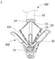
参照图1-5,本实施例提供的输送装置100包括输送鞘管10及操控件20。输送鞘管10包括连接端及操控端,其中,连接端指远离操作者、用于连接瓣膜夹合器300的一端,操控端指靠近操作者、远离瓣膜夹合器300的一端。如图1和图2所示,操控件20包括控制杆21、操控手柄22及连接头23,控制杆21活动地穿设于输送鞘管10内且可在输送鞘管10内沿输送鞘管10的延伸方向移动,如图3和图4所示,控制杆21包括空心管211及活动地穿设于空心管211内的插杆212,如图1、图2和图4所示,操控手柄22连接于空心管211及插杆212的一端且由输送鞘管10的操控端伸出,连接头23可拆卸地连接于空心管211的另一端。其中,连接头23用于连接近端夹片32,控制杆21用于连接操控手柄22与连接头23,操控手柄22用于带动空心管211与插杆212活动,以使连接头23与空心管211连接或断开,以及,使近端夹片32相对于固定座31收拢或展开。具体地,连接头23连接于空心管211上时,利用操控手柄22带动空心管211及插杆212朝向靠近输送鞘管10的操控端移动,可使近端夹片32相对于固定座31收拢;利用操控手柄22带动空心管211及插杆212朝向远离输送鞘管10的操控端移动,可使近端夹片32相对于固定座31展开。Referring to FIGS. 1-5 , the
需要说明的是,上述输送装置100用于输送并固定瓣膜夹合器300,瓣膜夹合器300固定至目标位置处后,需要将输送装置100的主体部分从瓣膜夹合器300上拆除并移出体外,其中,输送装置100的主体部分包括输送鞘管10、控制杆21及操控手柄22。此外,如图2和图10所示,传统瓣膜夹合器300的近端夹片32的自由端设有连接孔321,输送装置100的连接头23可连接于连接孔321。此外,控制杆21为柔性杆,利用操控件20控制近端夹片32收拢或展开的过程中,控制杆21可顺应近端夹片32的变形及转动角度而发生一定程度的变形,以避免输送鞘管10及输送装置100摆动。此外,瓣膜夹合器300还包括远端夹片33,近端夹片32与远端夹片33搭配使用并形成用于夹持瓣叶的夹钳,远端夹片33等结构与输送装置100不直接相连,在此不再详细赘述。It should be noted that the
本发明提供的输送装置100,包括输送鞘管10及操控件20,操控件20包括操控手柄22、连接于瓣膜夹合器300近端夹片32的连接头23以及用于连接操控手柄22及连接头23的控制杆21,通过控制操控手柄22,可带动控制杆21及连接头23移动,进而能够带动连接于连接头23的近端夹片32相对于固定座31收拢或展开,实现瓣膜夹合器300的输送及固定。其中,控制杆21设置于输送鞘管10内,可以免受人体组织的挤压,利用操控手柄22带动控制杆21移动时,摩擦阻力小,控制杆21移动方便且不易损伤人体组织,此外,控制杆21强度高,使用过程中不易断裂,可靠性高。进一步地,控制杆21包括空心管211及活动地穿设于空心管211内的插杆212,操控手柄22连接于空心管211及插杆212的一端,连接头23可拆卸地连接于空心管211的另一端,瓣膜夹合器300安装到位后,利用操控手柄22带动空心管211与插杆212活动,可快速断开连接头23与空心管211的连接,从而能够直接断开输送鞘管10、控制杆21及操控手柄22与瓣膜夹合器300的连接,操作难度小且快速方便。采用上述输送装置100输送并调节瓣膜夹合器300,能够有效缩短手术时长、提高手术成功率。The
可以理解,瓣膜夹合器300安装到位后,需要将输送装置100的主体部分移出体外,为降低输送装置100取放过程中因摩擦对人体组织产生的伤害,应保证输送鞘管10的外壁面光滑。It can be understood that after the
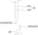
本实施例中,如图1、图2和图3所示,连接头23包括第一连接部231,控制杆21包括第二连接部2111,操控手柄22用于带动插杆212在第一连接部231及第二连接部2111内移动,以使空心管211与连接头23连接或断开。In this embodiment, as shown in FIG. 1 , FIG. 2 and FIG. 3 , the connecting
进一步地,如图1、图3和图4所示,第一连接部231为内部中空的连接管头,第二连接部2111为设置于空心管211连接于连接头23一端的弹性臂,弹性臂可伸入连接管头内并与连接管头相卡持。操控手柄22用于控制插杆212沿空心管211的轴向移动,以使插杆212在锁定状态及切换状态之间切换,其中,如图4所示,插杆212处于锁定状态时,插杆212伸入弹性臂之间并抵持弹性臂,使得弹性臂被夹持于插杆212及连接管头之间,弹性臂与连接管头相卡持,从而实现连接头23与空心管211的连接;如图3所示,插杆212处于解锁状态时,插杆212由弹性臂之间抽出并远离弹性臂,弹性臂恢复自然状态并在连接管头的径向上解除与连接头23的固定,从而弹性臂与连接管头可沿插杆212的轴向分离。可以理解,为确保插杆212的固定效果,插杆212的轴截面的尺寸略小于连接管头的内径。采用上述设计,通过移动空心管211与插杆212,即可完成控制杆21与连接头23的组装和拆卸,结构简单,使用方便,能够实现控制杆21与连接头23的快速拆装;此外,连接头23连接于空心管211上时,连接牢固,不易脱落。Further, as shown in Fig. 1, Fig. 3 and Fig. 4, the first connecting
进一步地,本实施例中,如图3和图4所示,弹性臂包括两个相对设置的弹片21111,沿指向弹片21111的自由端的方向,两个弹片21111呈渐缩结构,即两个弹片21111之间的间隙逐渐变小,弹性臂自由端的尺寸小于连接管头的内径。插杆212可伸入两个弹片21111之间并抵接于弹片21111内壁上,以使弹片21111与连接管头的内壁抵接。采用上述设计,弹性臂自由端尺寸较小,弹性臂与连接管头组装方便;此外,弹片21111结构简单,变形能力强,与连接管头的连接固定效果好,且不易损坏。Further, in this embodiment, as shown in Figure 3 and Figure 4, the elastic arm includes two opposite elastic pieces 21111, and along the direction pointing to the free ends of the elastic pieces 21111, the two elastic pieces 21111 are in a tapered structure, that is, two elastic pieces The gap between 21111 gradually becomes smaller, and the size of the free end of the elastic arm is smaller than the inner diameter of the connecting pipe head. The
为提升输送装置100的可靠性,本实施例中,如图2、图3和图4所示,连接管头的内壁上设有第一卡接结构,弹片21111的外壁上设有与第一卡接结构配合卡接的第二卡接结构。弹性臂插入连接管头内后,第一卡接结构与第二卡接结构位置相对,且插杆212处于锁定状态时,第一卡接结构与第二卡接结构对合卡接,用于限制弹性臂与连接管头在插杆212轴向上的位置。采用上述设计,能够进一步提高弹性臂与连接管头的连接固定效果,降低输送装置100使用过程中连接头23脱落风险,从而能够提高输送装置100的可靠性。In order to improve the reliability of the
可选地,如图3和图4所示,第一连接结构为卡槽,第二连接结构为与卡槽配合卡接的凸缘。其中,当弹性臂处于自然状态时,弹性臂上的凸缘与连接管头上的卡槽保持分离。Optionally, as shown in FIG. 3 and FIG. 4 , the first connection structure is a slot, and the second connection structure is a flange that engages with the slot. Wherein, when the elastic arm is in a natural state, the flange on the elastic arm is kept separated from the slot on the connecting pipe head.
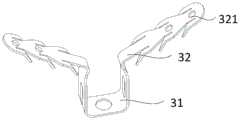
本实施例中,如2、图5和图10所示,连接头23包括连接近端夹片32的固定环232,固定环232穿设于近端夹片32的连接孔321上。利用固定环232连接输送装置100与近端夹片32,连接效果好,使用过程中连接头23不易从近端夹片32上脱落,可靠性高。可以理解,在一些实施例中,为方便连接近端夹片32与固定环232,如图11所示,还可在近端夹片32上设置挂钩322。In this embodiment, as shown in FIG. 2 , FIG. 5 and FIG. 10 , the
可以理解,在一些实施例中,连接头23包括连接近端夹片32的爪勾。It will be appreciated that in some embodiments, the
本实施例中,输送鞘管10为多腔管,输送鞘管10内包括多组输送腔。可选地,输送装置100包括两组操控件20,输送鞘管10包括两组沿其轴向延伸的输送腔,两组操控件20分别活动地设置于两组输送腔内。传统瓣膜夹合器300包括两组近端夹片32,每组近端夹片32对应连接于一组操控件20上,利用两组操控件20可独立控制两组近端夹片32。采用上述设计,每组操控件20单独设置于一输送腔内,独立性高,利用操控件20调节近端夹片32的开合时,多组操控件20间不会出现交叉及相互干扰,输送装置100不易损坏且便于实现近端夹片32开合角度的精准调节,可靠性高。In this embodiment, the
可选地,输送鞘管10内,两组输送腔中心对称设置,这样,利用操控件20调整近端夹片32的开合时,输送鞘管10径向受力均匀,有利于输送鞘管10保持平衡,从而能够有效避免输送鞘管10及输送装置100发生摆动,从而能够降低手术过程中对患者产生的伤害。Optionally, in the
进一步地,如图1、图2和图12所示,输送鞘管10的连接端还设有固定板24,固定板24上设有与输送腔相导通且用于供控制杆21穿过的定位孔241。采用上述结构,能够更好地定位控制杆21的位置,利用操控件20调节近端夹片32的开合时,多组操控件20间不会出现交叉及相互干扰,能够进一步提高近端夹片32位置调节的精准度。Further, as shown in FIG. 1 , FIG. 2 and FIG. 12 , the connection end of the
需要说明的是,输送鞘管10内还设有收容腔,如图2和图12所示,固定板24上设有与收容腔相导通的安装孔242,其中,收容腔用于安装瓣膜夹合器300的锁紧结构或其他连接结构。It should be noted that a receiving chamber is also provided in the
本实施例中,操控手柄22由输送鞘管10的操控端的管壁上伸出。输送鞘管10管壁上安装空间较大,便于安装操控手柄22,且操控手柄22安装于管壁上,使用方便。In this embodiment, the control handle 22 protrudes from the tube wall of the control end of the
可以理解,在一些实施例中,操控手柄22还可安装于输送鞘管10的端部,具体可根据实际情况进行设计,在此不做限定。It can be understood that, in some embodiments, the control handle 22 can also be installed at the end of the
本实施例中,连接头23为不锈钢材质。不锈钢材料具备强度高、耐腐蚀性好、焊接性能好及表面光洁等优点,采用不锈钢材料制备的连接头23强度高,使用过程中不易变形断裂且易于清洁,能够反复多次使用,实用性及可靠性高。In this embodiment, the connecting
可以理解,在一些实施例中,在满足安装要求及强度要求的前提下,连接头23还可采用钴合金、钛合金或其他金属材料制成,具体可根据实际情况进行设计,在此不作限定。It can be understood that in some embodiments, under the premise of meeting the installation requirements and strength requirements, the
本实施例中,插杆212为镍钛合金材质。镍钛合金具备密度低、无磁性、无毒及强度高等优点,采用镍钛合金制备插杆212强度高、质量轻,使用过程中不易变形损坏且易于拉动,使用方便。In this embodiment, the
可以理解,在一些实施例中,在满足使用要求及强度要求的前提下,插杆212还可采用不锈钢、钛合金、树脂或塑料等材料制成,具体可根据实际情况进行设计,在此不作限定。It can be understood that, in some embodiments, under the premise of meeting the use requirements and strength requirements, the
在一实施例中,空心管211为金属海波管。金属海波管具备柔性高、抗扭性能强及抗收缩性能好等优点,金属海波管使用时,可顺应近端夹片32的变形及转动角度发生一定程度的变形,并且能够抵抗人体组织的挤压,从而能够确保插杆212的正常使用,可靠性高。In one embodiment, the
可以理解,在一些实施例中,在满足使用要求及强度要求的前提下,空心管211还可为带编制网的复合管,具体可根据实际情况进行设计,在此不作限定。It can be understood that, in some embodiments, the
在一实施例中,空心管211的长度大于插杆212的长度。采用上述设计,结构合理,调节过程中,插杆212始终在空心管211内移动,不易损坏。In one embodiment, the length of the
可以理解,在一些实施例中,为方便操控或组装,插杆212的长度还可大于或等于空心管211的长度,具体可根据实际情况进行设计,在此不作限定。It can be understood that, in some embodiments, for the convenience of manipulation or assembly, the length of the
本发明提供的输送装置100用于瓣膜修复手术,包括但不限于二尖瓣的瓣膜修复、三尖膜的瓣膜修复。以下以二尖瓣的修复为例进行说明,本发明提供的输送装置100的具体使用方法如下:首先,将连接头23的固定环232安装于瓣膜夹合器300的近端夹片32上,并将空心管211的弹性臂插入连接头23的连接管头内,拉动操控手柄22,带动插杆212朝向弹性臂及连接管头一侧移动,并使弹性臂与连接管头锁紧,实现输送装置100与瓣膜夹合器300的固定连接;而后,利用输送装置100将瓣膜夹合器300输送至患者体内二尖瓣位置处,待瓣膜夹合器300到达目标位置后,拉动操控手柄22,带动控制杆21及连接头23朝向靠近或远离操控端的一侧来回移动,实现近端夹片32的角度调节,使瓣膜夹合器300夹住二尖瓣瓣叶;而后,拉动操控手柄22,带动控制杆21及连接头23朝向靠近操控端一侧移动,至近端夹片32相对于固定座31闭合,使得瓣膜夹合器300完全收拢;而后,拉动操控手柄22,带动插杆212朝向远离弹性臂及连接管头一侧移动,使得弹性臂与连接管头解锁,继续拉动操控手柄22,带动控制杆21及插杆212朝向远离连接管头及近端夹片32的一侧移动,使得控制杆21与连接头23及近端夹片32分离;而后,移出输送装置100的主体部分,并将瓣膜夹合器300及连接头23留置于患者体内。The
实施例二:Embodiment two:
参照图6-9,本实施例提供的输送装置100包括输送鞘管10及操控件20。如图1和图6所示,输送鞘管10包括连接端及操控端,操控件20包括控制杆21、操控手柄22及连接头23,控制杆21活动地穿设于输送鞘管10内且可在输送鞘管10内沿输送鞘管10的延伸方向移动。如图7和图8所示,控制杆21包括空心管211及活动地穿设于空心管211内的插杆212,如图1、图6和图8所示,操控手柄22连接于空心管211及插杆212的一端且由输送鞘管10的操控端伸出,连接头23可拆卸地连接于空心管211的另一端。其中,连接头23用于连接近端夹片32,控制杆21用于连接操控手柄22与连接头23,操控手柄22用于带动空心管211与插杆212活动,以使连接头23与空心管211连接或断开,以及,使近端夹片32相对于固定座31收拢或展开。Referring to FIGS. 6-9 , the
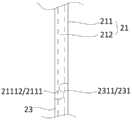
本实施例中,如图1、图7和图8所示,连接头23包括第一连接部231,控制杆21包括第二连接部2111,操控手柄22用于带动插杆212在第一连接部231及第二连接部2111内移动,以使空心管211与连接头23连接或断开。In this embodiment, as shown in FIG. 1 , FIG. 7 and FIG. 8 , the connecting
进一步地,如图1、图7和图8所示,第一连接部231为第一半管2311,第二连接部2111为第二半管21112,第一半管2311及第二半管21112的边缘处分别形成有可配合卡接的限位槽及限位凸缘,第一半管2311及第二半管21112对合后形成中空管结构,且限位槽与限位凸缘沿中空管的轴向相卡持;操控手柄22用于控制插杆212沿空心管211的轴向移动,以使插杆212在锁定状态及切换状态间切换,其中,如图8所示,插杆212处于锁定状态时,插杆212伸入第一半管2311与第二半管21112对合形成的中空管内,第一半管2311与第二半管21112沿插杆212的径向被锁定;如图7所示,插杆212处于解锁状态时,插杆212远离第一半管2311和第二半管21112,第一半管2311与第二半管21112可沿插杆212的径向分离。可以理解,为确保插杆212的固定效果,插杆212的轴截面的尺寸略小于第一半管2311与第二半管21112对合形成的中空管的内径。采用上述设计,通过移动空心管211与插杆212,即可完成控制杆21与连接头23的组装和拆卸,结构简单,使用方便,能够实现控制杆21与连接头23的快速拆装;此外,连接头23连接于空心管211上时,连接牢固,不易脱落。Further, as shown in Figure 1, Figure 7 and Figure 8, the first connecting part 231 is the first half pipe 2311, the second connecting part 2111 is the second half pipe 21112, the first half pipe 2311 and the second half pipe 21112 Limiting slots and limiting flanges are respectively formed at the edges of each other, and the first half pipe 2311 and the second half pipe 21112 are combined to form a hollow tube structure, and the limiting groove and the limiting flange are along the The axial phase of the hollow tube is clamped; the control handle 22 is used to control the axial movement of the insertion rod 212 along the hollow tube 211, so that the insertion rod 212 can be switched between the locked state and the switching state, wherein, as shown in Figure 8, When the insertion rod 212 is in the locked state, the insertion rod 212 extends into the hollow tube formed by the combination of the first half pipe 2311 and the second half pipe 21112 , and the first half pipe 2311 and the second half pipe 21112 are pulled along the radial direction of the insertion rod 212 Locking; as shown in Figure 7, when the insertion rod 212 is in the unlocked state, the insertion rod 212 is away from the first half pipe 2311 and the second half pipe 21112, and the first half pipe 2311 and the second half pipe 21112 can move along the diameter of the insertion rod 212 towards separation. It can be understood that, in order to ensure the fixing effect of the
进一步地,本实施例中,如图7和图8所示,第一半管2311及第二半管21112的边缘处为圆滑过渡的S形结构。采用上述设计,第一半管2311与第二半管21112组装方便,且组装过程中不易变形损坏。Further, in this embodiment, as shown in FIG. 7 and FIG. 8 , the edges of the first half pipe 2311 and the second half pipe 21112 are S-shaped structures with smooth transitions. With the above design, the first half pipe 2311 and the second half pipe 21112 are easy to assemble, and are not easily deformed and damaged during the assembly process.
本发明提供的输送装置100用于瓣膜修复手术,包括但不限于二尖瓣的瓣膜修复、三尖膜的瓣膜修复。以下以二尖瓣的修复为例进行说明,本发明提供的输送装置100的具体使用方法如下:首先,将连接头23的固定环232安装于瓣膜夹合器300的近端夹片32上,并将第一半管2311和第二半管21112对合形成中空管,带动插杆212朝向第一半管2311及第二半管21112一侧移动,并使第一半管2311与第二半管21112锁紧,实现输送装置100与瓣膜夹合器300的固定连接;而后,利用输送装置100将瓣膜夹合器300输送至患者体内二尖瓣位置处,待瓣膜夹合器300到达目标位置后,拉动操控手柄22,带动控制杆21及连接头23朝向靠近或远离操控端的一侧来回移动,实现近端夹片32的角度调节,使瓣膜夹合器300夹住二尖瓣瓣叶;而后,拉动操控手柄22,带动控制杆21及连接头23朝向靠近操控端一侧移动,至近端夹片32相对于固定座31闭合,使得瓣膜夹合器300完全收拢;而后,拉动操控手柄22,带动插杆212朝向远离第一半管2311及第二半管21112一侧移动,使得第一半管2311与第二半管21112解锁,继续拉动操控手柄22,带动控制杆21及插杆212朝向远离连接管头及近端夹片32的一侧移动,使得控制杆21与连接头23及近端夹片32分离;而后,移出输送装置100的主体部分,并将瓣膜夹合器300及连接头23留置于患者体内。The
实施例三:Embodiment three:
如图1和图2所示,本实施例提供的输送装置100包括输送鞘管10及操控件20。如图1和图6所示,输送鞘管10包括连接端及操控端,操控件20包括控制杆21、操控手柄22及连接头23,控制杆21活动地穿设于输送鞘管10内且可在输送鞘管10内沿输送鞘管10的延伸方向移动。如图7和图8所示,,控制杆21包括空心管211及活动地穿设于空心管211内的插杆212,如图1、图6和图8所示,操控手柄22连接于空心管211及插杆212的一端且由输送鞘管10的操控端伸出,连接头23可拆卸地连接于空心管211的另一端。其中,连接头23用于连接近端夹片32,控制杆21用于连接操控手柄22与连接头23,操控手柄22用于带动空心管211与插杆212活动,以使连接头23与空心管211连接或断开,以及,使近端夹片32相对于固定座31收拢或展开。As shown in FIGS. 1 and 2 , the
本实施例中,连接头23包括内部中空且内径与空心管211内径相同的连接管头,连接管头内壁、空心管211连接于连接管头一端的内壁及插杆212的外壁上设有螺纹结构。利用操控手柄22旋转插杆212,使插杆212的一端伸入连接管头内,可使空心管211及连接头23串联于插杆212上,从而能够实现空心管211与连接头23的连接固定;利用操控手柄22旋转插杆212,使插杆212与连接管头分离,可解除空心管211与连接头23的连接,从而能够实现空心管211与连接头23的分离。In this embodiment, the connecting
本发明提供的输送装置100用于瓣膜修复手术,包括但不限于二尖瓣的瓣膜修复、三尖膜的瓣膜修复。以下以二尖瓣的修复为例进行说明,本发明提供的输送装置100的具体使用方法如下:首先,将连接头23的固定环232安装于瓣膜夹合器300的近端夹片32上,并将空心管211的连接管头与连接头23的连接管头对合,带动插杆212朝向连接头23一侧移动,并使空心管211及连接头23均与插杆212锁紧,实现输送装置100与瓣膜夹合器300的固定连接;而后,利用输送装置100将瓣膜夹合器300输送至患者体内二尖瓣位置处,待瓣膜夹合器300到达目标位置后,拉动操控手柄22,带动控制杆21及连接头23朝向靠近或远离操控端的一侧来回移动,实现近端夹片32的角度调节,使瓣膜夹合器300夹住二尖瓣瓣叶;而后,拉动操控手柄22,带动控制杆21及连接头23朝向靠近操控端一侧移动,至近端夹片32相对于固定座31闭合,使得瓣膜夹合器300完全收拢;而后,拉动操控手柄22,带动插杆212朝向远离连接头23一侧移动,使得空心管211及连接头23均与插杆212解锁,继续拉动操控手柄22,带动控制杆21及插杆212朝向远离连接管头及近端夹片32的一侧移动,使得控制杆21与连接头23及近端夹片32分离;而后,移出输送装置100的主体部分,并将瓣膜夹合器300及连接头23留置于患者体内。The
第二方面,参照图1-12,本发明还提供了一种瓣膜夹合系统1,包括瓣膜夹合器300及输送装置100。如图1、图2和图6所示,输送鞘管10包括连接端及操控端,其中,连接端指远离操作者、用于连接瓣膜夹合器300的一端,操控端指靠近操作者、远离瓣膜夹合器300的一端。如图1、图2和图6所示,操控件20包括控制杆21、操控手柄22及连接头23,控制杆21活动地穿设于输送鞘管10内且可在输送鞘管10内沿输送鞘管10的延伸方向移动,如图3和图4所示,如图1、图2和图4所示,控制杆21包括空心管211及活动地穿设于空心管211内的插杆212,如图所示,操控手柄22连接于空心管211及插杆212的一端且由输送鞘管10的操控端伸出,连接头23可拆卸地连接于空心管211的另一端。其中,连接头23用于连接近端夹片32,控制杆21用于连接操控手柄22与连接头23,操控手柄22用于带动空心管211与插杆212活动,以使连接头23与空心管211连接或断开,以及,使近端夹片32相对于固定座31收拢或展开。具体地,连接头23连接于空心管211上时,利用操控手柄22带动空心管211及插杆212朝向靠近输送鞘管10的操控端移动,可使近端夹片32相对于固定座31收拢;利用操控手柄22带动空心管211及插杆212朝向远离输送鞘管10的操控端移动,可使近端夹片32相对于固定座31展开。In the second aspect, referring to FIGS. 1-12 , the present invention also provides a
本实施例提供的瓣膜夹合系统1中,输送装置100包括鞘管及操控件20,操控件20包括操控手柄22、连接于瓣膜夹合器300近端夹片32的连接头23以及用于连接操控手柄22及连接头23的控制杆21,通过控制操控手柄22,可带动控制杆21及连接头23移动,进而能够带动连接于连接头23的近端夹片32相对于固定座31收拢或展开,实现瓣膜夹合器300的输送及固定。其中,控制杆21设置于输送鞘管10内,可以免受人体组织的挤压,利用操控手柄22带动控制杆21移动时,摩擦阻力小,控制杆21移动方便且不易损伤人体组织,此外,控制杆21强度高,使用过程中不易断裂,可靠性高。进一步地,控制杆21包括空心管211及活动地穿设于空心管211内的插杆212,操控手柄22连接于空心管211及插杆212的一端,连接头23可拆卸地连接于空心管211的另一端,瓣膜夹合器300安装到位后,利用操控手柄22带动空心管211与插杆212活动,可快速断开连接头23与空心管211的连接,从而能够直接断开输送鞘管10、控制杆21及操控手柄22与瓣膜夹合器300的连接,操作难度小且快速方便。采用上述输送装置100输送并调节瓣膜夹合器300,能够有效缩短手术时长、提高手术成功率。In the
如图2、图5和10所示,本实施例提供的瓣膜夹合器300的近端夹片32上设有连接孔321,连接孔321可与挂钩、固定环232等结构实现挂扣。其中,近端夹片32由弹性材料制备,例如,可采用镍钛、不锈钢、高分子等材料制备。可选地,近端夹片32采用镍钛材料制备。As shown in FIG. 2 , FIG. 5 and FIG. 10 , the
以上所述实施例仅用以说明本申请的技术方案,而非对其限制;尽管参照前述实施例对本申请进行了详细的说明,本领域的普通技术人员应当理解:其依然可以对前述各实施例所记载的技术方案进行修改,或者对其中部分技术特征进行等同替换;而这些修改或者替换,并不使相应技术方案的本质脱离本申请各实施例技术方案的精神和范围,均应包含在本申请的保护范围之内。The above-described embodiments are only used to illustrate the technical solutions of the present application, rather than to limit them; although the present application has been described in detail with reference to the foregoing embodiments, those of ordinary skill in the art should understand that: it can still implement the foregoing embodiments Modifications to the technical solutions described in the examples, or equivalent replacements for some of the technical features; and these modifications or replacements do not make the essence of the corresponding technical solutions deviate from the spirit and scope of the technical solutions of the various embodiments of the application, and should be included in the Within the protection scope of this application.
Claims (10)
Translated fromChinesePriority Applications (1)
| Application Number | Priority Date | Filing Date | Title |
|---|---|---|---|
| CN202111426544.0ACN116172750A (en) | 2021-11-27 | 2021-11-27 | Delivery Devices and Valve Clamping Systems |
Applications Claiming Priority (1)
| Application Number | Priority Date | Filing Date | Title |
|---|---|---|---|
| CN202111426544.0ACN116172750A (en) | 2021-11-27 | 2021-11-27 | Delivery Devices and Valve Clamping Systems |
Publications (1)
| Publication Number | Publication Date |
|---|---|
| CN116172750Atrue CN116172750A (en) | 2023-05-30 |
Family
ID=86435032
Family Applications (1)
| Application Number | Title | Priority Date | Filing Date |
|---|---|---|---|
| CN202111426544.0APendingCN116172750A (en) | 2021-11-27 | 2021-11-27 | Delivery Devices and Valve Clamping Systems |
Country Status (1)
| Country | Link |
|---|---|
| CN (1) | CN116172750A (en) |
Citations (2)
| Publication number | Priority date | Publication date | Assignee | Title |
|---|---|---|---|---|
| CN102395331A (en)* | 2009-02-26 | 2012-03-28 | 埃瓦尔维公司 | Detachment mechanism for implantable fixation devices |
| CN111789699A (en)* | 2019-11-19 | 2020-10-20 | 杭州德晋医疗科技有限公司 | Independently controllable valve clamping system |
- 2021
- 2021-11-27CNCN202111426544.0Apatent/CN116172750A/enactivePending
Patent Citations (2)
| Publication number | Priority date | Publication date | Assignee | Title |
|---|---|---|---|---|
| CN102395331A (en)* | 2009-02-26 | 2012-03-28 | 埃瓦尔维公司 | Detachment mechanism for implantable fixation devices |
| CN111789699A (en)* | 2019-11-19 | 2020-10-20 | 杭州德晋医疗科技有限公司 | Independently controllable valve clamping system |
Similar Documents
| Publication | Publication Date | Title |
|---|---|---|
| CN110537946A (en) | Tissue clamping device and method of use thereof | |
| US8460369B2 (en) | Tools for removal and installation of exchangeable cardiovascular valves | |
| JP2018525080A (en) | Valvular closure | |
| CN111772874A (en) | A valve clamp and its clamping system | |
| CN106890012A (en) | Handle for delivery catheter and method of use thereof | |
| US12083014B2 (en) | Fixing device for clamping tissue | |
| CN111920550A (en) | Valve repair device, delivery device and valve repair system | |
| CN111772875A (en) | Compressible valve clamping device and clamping system thereof | |
| EP4079260A1 (en) | Controllable guiding device for implantable apparatus | |
| WO2014044212A1 (en) | Implant conveying system | |
| CN211485094U (en) | Compressible valve clamping device and clamping system thereof | |
| CN114271993B (en) | Valve repair device | |
| WO2024065977A1 (en) | Valve leaflet flow blocking repair clamp and repair system thereof | |
| CN115429492B (en) | Valve clamping device and valve clamping system | |
| CN115517826A (en) | Mitral valve clamping device and mitral valve clamping system | |
| WO2023125162A1 (en) | Valve clip and valve clip system | |
| CN215915077U (en) | Delivery system for implantable tissue fixation devices | |
| CN114652489A (en) | Valve repair system and coupling device therefor | |
| CN113456297A (en) | Clamping apparatus | |
| EP4338707A1 (en) | Clamping instrument | |
| CN216294350U (en) | Clamping device | |
| WO2022143163A1 (en) | Connecting mechanism and valve repairing system | |
| CN116172749A (en) | Delivery Devices and Valve Clamping Systems | |
| CN116172750A (en) | Delivery Devices and Valve Clamping Systems | |
| WO2021082821A1 (en) | Valve clamp capable of detecting valve gripped state, and valve clamping system |
Legal Events
| Date | Code | Title | Description |
|---|---|---|---|
| PB01 | Publication | ||
| PB01 | Publication | ||
| SE01 | Entry into force of request for substantive examination | ||
| SE01 | Entry into force of request for substantive examination |