CN116160100A - Plasma cutting device for automatic steel pipe feeding - Google Patents
Plasma cutting device for automatic steel pipe feedingDownload PDFInfo
- Publication number
- CN116160100A CN116160100ACN202310429961.3ACN202310429961ACN116160100ACN 116160100 ACN116160100 ACN 116160100ACN 202310429961 ACN202310429961 ACN 202310429961ACN 116160100 ACN116160100 ACN 116160100A
- Authority
- CN
- China
- Prior art keywords
- steel pipe
- plasma cutting
- roller
- chuck
- cutting
- Prior art date
- Legal status (The legal status is an assumption and is not a legal conclusion. Google has not performed a legal analysis and makes no representation as to the accuracy of the status listed.)
- Granted
Links
Images


Classifications
- B—PERFORMING OPERATIONS; TRANSPORTING
- B23—MACHINE TOOLS; METAL-WORKING NOT OTHERWISE PROVIDED FOR
- B23K—SOLDERING OR UNSOLDERING; WELDING; CLADDING OR PLATING BY SOLDERING OR WELDING; CUTTING BY APPLYING HEAT LOCALLY, e.g. FLAME CUTTING; WORKING BY LASER BEAM
- B23K10/00—Welding or cutting by means of a plasma
- B—PERFORMING OPERATIONS; TRANSPORTING
- B23—MACHINE TOOLS; METAL-WORKING NOT OTHERWISE PROVIDED FOR
- B23K—SOLDERING OR UNSOLDERING; WELDING; CLADDING OR PLATING BY SOLDERING OR WELDING; CUTTING BY APPLYING HEAT LOCALLY, e.g. FLAME CUTTING; WORKING BY LASER BEAM
- B23K2101/00—Articles made by soldering, welding or cutting
- B23K2101/04—Tubular or hollow articles
- B23K2101/06—Tubes
- B—PERFORMING OPERATIONS; TRANSPORTING
- B23—MACHINE TOOLS; METAL-WORKING NOT OTHERWISE PROVIDED FOR
- B23K—SOLDERING OR UNSOLDERING; WELDING; CLADDING OR PLATING BY SOLDERING OR WELDING; CUTTING BY APPLYING HEAT LOCALLY, e.g. FLAME CUTTING; WORKING BY LASER BEAM
- B23K2103/00—Materials to be soldered, welded or cut
- B23K2103/02—Iron or ferrous alloys
- B23K2103/04—Steel or steel alloys
- Y—GENERAL TAGGING OF NEW TECHNOLOGICAL DEVELOPMENTS; GENERAL TAGGING OF CROSS-SECTIONAL TECHNOLOGIES SPANNING OVER SEVERAL SECTIONS OF THE IPC; TECHNICAL SUBJECTS COVERED BY FORMER USPC CROSS-REFERENCE ART COLLECTIONS [XRACs] AND DIGESTS
- Y02—TECHNOLOGIES OR APPLICATIONS FOR MITIGATION OR ADAPTATION AGAINST CLIMATE CHANGE
- Y02P—CLIMATE CHANGE MITIGATION TECHNOLOGIES IN THE PRODUCTION OR PROCESSING OF GOODS
- Y02P70/00—Climate change mitigation technologies in the production process for final industrial or consumer products
- Y02P70/10—Greenhouse gas [GHG] capture, material saving, heat recovery or other energy efficient measures, e.g. motor control, characterised by manufacturing processes, e.g. for rolling metal or metal working
Landscapes
- Engineering & Computer Science (AREA)
- Physics & Mathematics (AREA)
- Plasma & Fusion (AREA)
- Mechanical Engineering (AREA)
- Arc Welding In General (AREA)
Abstract
Description
Translated fromChinese技术领域technical field
本发明涉及钢管加工装置技术领域,具体涉及一种钢管自动上料的等离子切割装置。The invention relates to the technical field of steel pipe processing devices, in particular to a plasma cutting device for automatic feeding of steel pipes.
背景技术Background technique
随着等离子技术和应用的发展,在机械加工行业,钢管切割通常采用等离子切割机进行切断。当一段钢管切断后,需要对钢管传送递进,然后截取另一段钢管,对于被切钢管的递送工作,采用人操作,工效率低。With the development of plasma technology and application, in the machining industry, steel pipe cutting is usually cut by plasma cutting machine. After a section of steel pipe is cut off, it is necessary to transfer and advance the steel pipe, and then intercept another section of steel pipe. For the delivery work of the cut steel pipe, human operation is adopted, and the work efficiency is low.
中国专利CN 106216823B公开了一种双向同步夹紧式等离子钢管切断装备,可以实现夹紧机构在两个方向上对钢管实现同步夹紧,利用递送夹紧装置,可以实现对钢管进行定距递送,但是该切断装备不能自动上料,同时,该切断装备在切割的过程中对钢管进行旋转夹持,增加了设备的复杂程度和精度要求。Chinese patent CN 106216823B discloses a two-way synchronous clamping type plasma steel pipe cutting equipment, which can realize the simultaneous clamping of the steel pipe by the clamping mechanism in two directions, and the fixed-distance delivery of the steel pipe can be realized by using the delivery clamping device. However, the cutting equipment cannot automatically load materials, and at the same time, the cutting equipment rotates and clamps the steel pipe during the cutting process, which increases the complexity and precision requirements of the equipment.
基于此,本发明提出了一种钢管自动上料的等离子切割装置。Based on this, the present invention proposes a plasma cutting device for automatic feeding of steel pipes.
发明内容Contents of the invention
针对上述现有技术的不足之处,本发明提供了一种钢管自动上料的等离子切割装置,传动系统既能存放钢管又能向传动架传送钢管,视觉识别系统识别钢管的外径和壁厚,夹持长度测量机构测量钢管的长度,为钢管的切割工序提供数据支撑。Aiming at the shortcomings of the above-mentioned prior art, the present invention provides a plasma cutting device for automatic feeding of steel pipes. The transmission system can not only store steel pipes but also transmit steel pipes to the transmission frame. The visual recognition system can identify the outer diameter and wall thickness of steel pipes. , the clamping length measuring mechanism measures the length of the steel pipe, providing data support for the cutting process of the steel pipe.
一种钢管自动上料的等离子切割装置,包括上料机构、截面识别机构、夹持长度测量机构、等离子切割机构和料头收集框;A plasma cutting device for automatic feeding of steel pipes, comprising a feeding mechanism, a section identification mechanism, a clamping length measuring mechanism, a plasma cutting mechanism, and a scrap collection frame;
上料机构包括上料支架、传动系统、传动架和U型卡件,所述传动系统包括电动机、连接轴、传动齿轮和链条,链条平常处于松弛状态,呈U型,用于存放钢管,当总控系统发出指令需上料时,2台电动机运转,带动连接轴旋转,通过传动齿轮转动收紧链条,进而带动钢管按总控系统要求摆放在传动架上,根据加工进度,转动轴启动,调节传动架的角度,使钢管滑入钢管U型卡件内;The feeding mechanism includes a feeding bracket, a transmission system, a transmission frame and a U-shaped clip. The transmission system includes a motor, a connecting shaft, a transmission gear and a chain. The chain is usually in a loose state and is U-shaped, and is used to store steel pipes. When the master control system issues an instruction to load materials, the two motors run to drive the connecting shaft to rotate, and the transmission gear rotates to tighten the chain, and then drives the steel pipe to be placed on the transmission frame according to the requirements of the master control system. According to the processing progress, the rotating shaft starts , adjust the angle of the transmission frame, so that the steel pipe slides into the U-shaped clamp of the steel pipe;
截面识别机构,具有视觉识别系统,当钢管滑入钢管U型卡件内时,视觉识别系统首先对钢管端部拍照,再对钢管的外径和壁厚进行识别,传输至总控系统,为钢管的切割工序提供数据支撑;The section recognition mechanism has a visual recognition system. When the steel pipe slides into the U-shaped clamp of the steel pipe, the visual recognition system first takes a picture of the end of the steel pipe, and then recognizes the outer diameter and wall thickness of the steel pipe, and transmits it to the master control system. The cutting process of the steel pipe provides data support;
夹持长度测量机构,在靠近等离子切割机构的一端设有固定卡,在另一端设有卡盘,卡盘与卡盘移动座固定,卡盘移动座可沿着卡盘移动轨道的长度方向移动,截面识别后的钢管滑入升降托辊,升降托辊可上下调整位置,以便卡盘卡紧钢管,并沿着卡盘移动轨道向固定卡方向移动,直至钢管另一端抵住固定卡,通过固定卡和卡盘上的传感器,测量出钢管的长度,至此,钢管的长度、截面规格均已测量完毕;The clamping length measuring mechanism has a fixed card at one end close to the plasma cutting mechanism, and a chuck at the other end, the chuck is fixed with the chuck moving seat, and the chuck moving seat can move along the length direction of the chuck moving track , the steel pipe after cross-section identification slides into the lifting roller, and the lifting roller can adjust its position up and down so that the chuck can clamp the steel pipe, and move along the chuck moving track to the direction of the fixed card until the other end of the steel pipe is against the fixed card. Fix the clamp and the sensor on the chuck to measure the length of the steel pipe. So far, the length and cross-sectional specifications of the steel pipe have been measured;
等离子切割机构,包括2台等离子切割机、2台切割机移动座、1条切割机移动轨道、2台滚轮移动座、1条滚轮移动轨道、2台烟尘收集器和多个等离子切割枪头,2台滚轮移动座根据钢管的长度在滚轮移动轨道移动,2台滚轮移动座顶部放置待切割的钢管,支撑钢管,根据总控系统发出的指令,根据所需成品钢管的长度,2台等离子切割机在切割机移动轨道运动,两者间距与成品钢管长度保持一致,从而实现成品钢管的定长切割,切割过程中,烟尘收集器对切割所产生的烟尘进行收集。Plasma cutting mechanism, including 2 plasma cutting machines, 2 cutting machine moving seats, 1 cutting machine moving track, 2 roller moving seats, 1 roller moving track, 2 smoke collectors and multiple plasma cutting torch heads, 2 roller moving seats move on the roller moving track according to the length of the steel pipe. The steel pipe to be cut is placed on the top of the 2 roller moving seats to support the steel pipe. According to the instructions issued by the master control system, according to the length of the finished steel pipe, 2 plasma cutting machines The machine moves on the moving track of the cutting machine, and the distance between the two is consistent with the length of the finished steel pipe, so as to realize the fixed-length cutting of the finished steel pipe. During the cutting process, the smoke dust collector collects the smoke generated by cutting.
进一步的,成品钢管的长度通过2台等离子切割机之间的间距实现,切割时,根据总控系统发出的指令确定等离子切割枪头与钢管的角度,对于壁厚不大于4mm的钢管,切割角度为90度,大于4mm的钢管,切割角度为内切45度并打坡口。Further, the length of the finished steel pipe is realized by the distance between two plasma cutting machines. When cutting, the angle between the plasma cutting gun head and the steel pipe is determined according to the instructions issued by the master control system. For steel pipes with a wall thickness not greater than 4mm, the cutting angle 90 degrees, steel pipes larger than 4mm, the cutting angle is 45 degrees inscribed and beveled.
进一步的,卡盘设有垂直相交十字凹形卡槽,里面安装有4个活动卡扣,当活动卡扣靠近十字凹形卡槽中心时,卡盘不具备卡紧钢管功能,当卡盘伸入钢管端头内部,总控系统发出指令,4个活动卡扣分别从中心沿着十字凹形卡槽向外运动,4个活动卡扣抵住钢管端头的内壁,实现固定钢管的功能。Further, the chuck is provided with vertically intersecting cross concave grooves, and 4 movable buckles are installed inside. When the movable buckles are close to the center of the cross concave grooves, the chuck does not have the function of clamping the steel pipe. When the chuck extends Enter the interior of the steel pipe end, the master control system issues instructions, and the four movable buckles move outward from the center along the cross concave groove, and the four movable buckles are against the inner wall of the steel pipe end to realize the function of fixing the steel pipe.
进一步的,升降托辊包括1个主辊轮、4个辅助辊轮、升降电机和滚轮连接件,主辊轮通过辊轴安装于滚轮固定架上表面,4个辅助辊轮呈2列分布,2列辅助辊轮所形成凹槽与1个主辊轮中间的凹槽保持对中,滚轮固定架与升降电机通过滚轮连接件连接,工作时,钢管固定于辅助辊轮之间和主辊轮中间的凹槽内,通过升降电机带动滚轮固定架上下移动,实现钢管高度的移动,确保截面规格识别、长度测量和等离子切割的精度。Further, the lifting roller includes 1 main roller, 4 auxiliary rollers, a lifting motor and roller connectors. The main roller is installed on the upper surface of the roller fixing frame through the roller shaft, and the 4 auxiliary rollers are distributed in 2 rows. The groove formed by the 2 rows of auxiliary rollers is aligned with the groove in the middle of one main roller. The roller fixing frame and the lifting motor are connected through roller connectors. When working, the steel pipe is fixed between the auxiliary rollers and the main roller. In the middle groove, the lifting motor drives the roller fixing frame to move up and down to realize the movement of the height of the steel pipe, ensuring the accuracy of section specification identification, length measurement and plasma cutting.
进一步的,包括以下步骤:钢管成捆放置在上料机构中,通过传动系统和转动轴将钢管传送到U型卡件中,利用截面识别机构对钢管截面进行识别,识别后通过夹持长度测量机构进行长度测量,最终根据总控系统的指令,利用等离子切割机构将钢管切割成加工所需要长度,切割后剩余的料头存放于料头收集框中;实现钢管上料、截面规格识别、长度测量和等离子切割,最终输出加工所需要的定长定截面钢管。Further, it includes the following steps: the steel pipes are placed in bundles in the feeding mechanism, the steel pipes are transferred to the U-shaped clip through the transmission system and the rotating shaft, the cross-section of the steel pipes is recognized by the cross-section recognition mechanism, and the cross-section of the steel pipes is measured by the clamping length after recognition The mechanism measures the length, and finally according to the instructions of the master control system, the plasma cutting mechanism is used to cut the steel pipe into the length required for processing, and the remaining scrap after cutting is stored in the scrap collection box; to realize steel pipe feeding, section specification identification, length Measurement and plasma cutting, and finally output the fixed-length and fixed-section steel pipe required for processing.
由于采用上述技术方案,与现有技术相比,本发明的有益效果为:Owing to adopting above-mentioned technical scheme, compared with prior art, the beneficial effect of the present invention is:
本发明传动系统的链条平常处于松弛状态,呈U型,能够用于存放钢管,当总控系统发出指令需上料后,转动的传动齿轮使得链条收紧,转动轴调节传动架的角度,使钢管滑入钢管U型卡件内,便于视觉识别系统对钢管端头进行拍照识别;The chain of the transmission system of the present invention is usually in a loose state and is U-shaped, which can be used to store steel pipes. After the master control system issues an instruction to load materials, the rotating transmission gear makes the chain tighten, and the rotating shaft adjusts the angle of the transmission frame, so that The steel pipe slides into the U-shaped clip of the steel pipe, which is convenient for the visual recognition system to take pictures and identify the end of the steel pipe;
本发明通过卡盘和固定卡对钢管进行夹持,2台等离子切割机在切割机移动轨道运动,两者间距与成品钢管长度保持一致,每切割完一段钢管后,卡盘移动座继续推动卡盘和钢管余料与固定卡抵接,在切割的过程中,无需旋转钢管。The invention clamps the steel pipe through the chuck and the fixed clip, and the two plasma cutting machines move on the moving track of the cutting machine, and the distance between the two is consistent with the length of the finished steel pipe. The remaining material of the disk and the steel pipe is in contact with the fixed card, and there is no need to rotate the steel pipe during the cutting process.
本发明截面识别机构通过视觉识别系统对钢管端头进行拍照识别,将钢管的外径和壁厚传输至总控系统,为钢管的切割工序提供数据支撑,选择对应角度的等离子切割枪头,使得切割后的成品钢管的端头满足质量要求。The cross-section recognition mechanism of the present invention takes pictures and recognizes the end of the steel pipe through the visual recognition system, transmits the outer diameter and wall thickness of the steel pipe to the general control system, provides data support for the cutting process of the steel pipe, and selects the plasma cutting gun head of the corresponding angle, so that The ends of the finished steel pipes after cutting meet the quality requirements.
夹持长度测量机构测量出钢管的长度,使得总控系统能够计算出钢管能够切割的段数,避免无效切割。The clamping length measuring mechanism measures the length of the steel pipe, so that the master control system can calculate the number of segments that can be cut by the steel pipe to avoid invalid cutting.
滚轮移动座沿滚轮移动轨道滑动,能够在钢管余料逐渐缩短的过程中,通过滚轮移动座的移动,始终对钢管进行有效稳定的支撑。The roller moving seat slides along the roller moving track, and can always provide effective and stable support for the steel pipe through the movement of the roller moving seat in the process of gradually shortening the remaining material of the steel pipe.
附图说明Description of drawings
图1为本发明的整体结构示意图;Fig. 1 is the overall structure schematic diagram of the present invention;
图2为上料机构的结构示意图;Fig. 2 is the structural representation of feeding mechanism;
图3为上料机构的局部结构示意图;Fig. 3 is the partial structure schematic diagram of feeding mechanism;
图4为截面识别机构的结构示意图;Fig. 4 is a structural schematic diagram of a section identification mechanism;
图5为夹持长度测量机构和等离子切割机构的正面轴视图;Fig. 5 is the front axial view of clamping length measuring mechanism and plasma cutting mechanism;
图6为夹持长度测量机构和等离子切割机构的背面轴视图;Fig. 6 is the rear axial view of the clamping length measuring mechanism and the plasma cutting mechanism;
图7为等离子切割机构的结构示意图;Fig. 7 is a schematic structural diagram of a plasma cutting mechanism;
图8为等离子切割枪头的结构示意图;Fig. 8 is a schematic structural view of a plasma cutting gun head;
图9为卡盘的结构示意图;Fig. 9 is the structural representation of chuck;
图10为升降托辊的结构示意图;Figure 10 is a schematic structural view of the lifting roller;
图11为本发明总控系统的流程图;Fig. 11 is the flow chart of master control system of the present invention;
附图标记,1-上料机构,101-上料支架,102-电动机,103-连接轴,104-传动齿轮,105-链条,106-传动架,107-U型卡件,108-转动轴;Reference signs, 1-feeding mechanism, 101-feeding bracket, 102-motor, 103-connecting shaft, 104-transmission gear, 105-chain, 106-transmission frame, 107-U-shaped clip, 108-rotation shaft ;
2-截面识别机构;2- Section identification mechanism;
3-夹持长度测量机构,301-卡盘,302-卡盘移动座,303-卡盘移动轨道,304-升降托辊,305-活动卡扣,306-主辊轮,307-滚轮固定架,308-辅助辊轮,309-升降电机,310-滚轮连接件,311-固定卡;3- clamping length measuring mechanism, 301- chuck, 302- chuck moving seat, 303- chuck moving track, 304- lifting roller, 305- movable buckle, 306- main roller, 307- roller fixing frame , 308-auxiliary roller, 309-lifting motor, 310-roller connector, 311-fixing card;
4-等离子切割机构,401-等离子切割机,402-切割机移动座,403-切割机移动轨道,404-滚轮移动座,405-烟尘收集器,406-滚轮移动轨道,407-等离子切割枪头;4-Plasma cutting mechanism, 401-Plasma cutting machine, 402-Cutting machine moving seat, 403-Cutting machine moving track, 404-Roller moving seat, 405-Smoke dust collector, 406-Roller moving track, 407-Plasma cutting gun head ;
5-料头收集框。5-Scrap collection box.
具体实施方式Detailed ways
下面将结合本发明实施例中的附图,对本发明实施例种的技术方案进行清楚、完整的描述,显然,所描述的实施例仅是本发明一部分实施例,而不是全部的实施例。基于本发明中的实施例,本领域技术人员在没有作出创造性劳动前提下说获得的其他实施方式或等同替换,都在本发明的保护范围内。The technical solutions of the embodiments of the present invention will be clearly and completely described below in conjunction with the accompanying drawings in the embodiments of the present invention. Obviously, the described embodiments are only some, not all, embodiments of the present invention. Based on the embodiments of the present invention, other implementation modes or equivalent replacements obtained by those skilled in the art without creative work are all within the protection scope of the present invention.
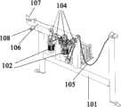
如图1所示,一种钢管自动上料的等离子切割装置,包括上料机构1、截面识别机构2、夹持长度测量机构3、等离子切割机构4和料头收集框5;As shown in Figure 1, a plasma cutting device for automatic feeding of steel pipes includes a feeding mechanism 1, a
如图2和图3所示,上料机构1包括上料支架101、传动系统、传动架106和U型卡件107,所述传动系统包括电动机102、连接轴103、传动齿轮104和链条105,链条105平常处于松弛状态,呈U型,用于存放钢管,当总控系统发出指令需上料时,2台电动机102运转,带动连接轴103旋转,通过传动齿轮104转动收紧链条105,进而带动钢管按总控系统要求摆放在传动架106上,根据加工进度,转动轴108启动,调节传动架106的角度,使钢管滑入钢管U型卡件107内;As shown in Figures 2 and 3, the feeding mechanism 1 includes a
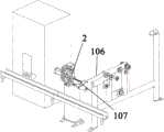
如图4所示,截面识别机构2,具有视觉识别系统,当钢管滑入钢管U型卡件107内时,视觉识别系统首先对钢管端部拍照,再对钢管的外径和壁厚进行识别,传输至总控系统,为钢管的切割工序提供数据支撑;As shown in Figure 4, the
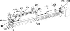
如图5所示,夹持长度测量机构3,在靠近等离子切割机构4的一端设有固定卡311,在另一端设有卡盘301,卡盘301与卡盘移动座302固定,卡盘移动座302可沿着卡盘移动轨道303的长度方向移动,截面识别后的钢管滑入升降托辊304,升降托辊304可上下调整位置,以便卡盘301卡紧钢管,并沿着卡盘移动轨道303向固定卡311方向移动,直至钢管另一端抵住固定卡311,通过在固定卡311和卡盘301上的传感器,测量出钢管的长度,至此,钢管的长度、截面规格均已测量完毕;As shown in Figure 5, the clamping
如图6和图7所示,等离子切割机构4,包括2台等离子切割机401、2台切割机移动座402、1条切割机移动轨道403、2台滚轮移动座404、1条滚轮移动轨道406、2台烟尘收集器405和多个等离子切割枪头407,2台滚轮移动座404根据钢管的长度在滚轮移动轨道406移动,2台滚轮移动座404顶部放置待切割的钢管,支撑钢管,根据总控系统发出的指令,根据所需成品钢管的长度,2台等离子切割机401在切割机移动轨道403运动,两者间距与成品钢管长度保持一致,从而实现成品钢管的定长切割,切割过程中,烟尘收集器405对切割所产生的烟尘进行收集。As shown in Figures 6 and 7, the
如图8所示,成品钢管的长度通过2台等离子切割机401之间的间距实现,切割时,根据总控系统发出的指令确定等离子切割枪头407与钢管的角度,对于壁厚不大于4mm的钢管,切割角度为90度,大于4mm的钢管,切割角度为内切45度并打坡口。As shown in Figure 8, the length of the finished steel pipe is realized by the distance between two
如图9所示,卡盘301设有垂直相交十字凹形卡槽,里面安装有4个活动卡扣305,当活动卡扣305靠近十字凹形卡槽中心时,卡盘301不具备卡紧钢管功能,当卡盘301伸入钢管端头内部,总控系统发出指令,4个活动卡扣305分别从中心沿着十字凹形卡槽向外运动,4个活动卡扣305抵住钢管端头的内壁,实现固定钢管的功能。As shown in Figure 9, the
如图10所示,升降托辊304包括1个主辊轮306、4个辅助辊轮308、升降电机309和滚轮连接件310,主辊轮306通过辊轴安装于滚轮固定架307上表面,4个辅助辊轮308呈2列分布,2列辅助辊轮308所形成凹槽与1个主辊轮306中间的凹槽保持对中,滚轮固定架307与升降电机309通过滚轮连接件310连接,工作时,钢管固定于辅助辊轮308之间和主辊轮306中间的凹槽内,通过升降电机309带动滚轮固定架307上下移动,实现钢管高度的移动,确保截面规格识别、长度测量和等离子切割的精度。As shown in Figure 10, the lifting
如图11所示,本发明工作的具体步骤为:As shown in Figure 11, the concrete steps of the present invention work are:
钢管上料:总控系统发出上料指令,电动机102运转,传动齿轮104转动收紧链条105,转动轴108启动,调节传动架106的角度,钢管滑入钢管U型卡件107内;Steel pipe feeding: the master control system issues a feeding command, the
截面规格识别:视觉识别系统对U型卡件107内的钢管端头进行拍照识别,将识别的钢管外径和壁厚传输至总控系统;Recognition of cross-section specifications: the visual recognition system takes pictures of the steel pipe ends in the
长度测量:钢管滑入升降托辊304,落入辅助辊轮308之间、主辊轮306中间的凹槽内,升降电机309带动滚轮固定架307上下移动,钢管同步移动,至钢管的端头与卡盘301对准,在卡盘移动座302的作用下,卡盘301伸入钢管端头内部,总控系统发出指令,4个活动卡扣305分别从中心沿着十字凹形卡槽向外运动,4个活动卡扣305抵住钢管端头的内壁,从而使卡盘301卡紧钢管,卡盘移动座302带着卡盘301和钢管沿着卡盘移动轨道303向固定卡311方向移动,直至钢管另一端抵住固定卡311,通过在固定卡311和卡盘301上的传感器,测量出钢管的长度;Length measurement: the steel pipe slides into the lifting
等离子切割:2台等离子切割机401在切割机移动轨道403运动,两者间距与成品钢管长度保持一致,根据总控系统发出的指令确定等离子切割枪头407与钢管的角度,等离子切割枪头407对钢管进行切割;Plasma cutting: two
下料和回收:切割完成后,等离子切割枪头407复位,钢管余料前推,成品钢管落入下方的料头收集框5,至钢管完成多次切割后,卡盘301向远离固定卡311的方向移动复位,活动卡扣305反方向移动,卡盘301与剩余的钢管分离,剩余的钢管落入下方的料头收集框5。Cutting and recycling: After the cutting is completed, the plasma
以上公开的本发明优选实施例只是用于帮助阐述本发明。优选实施例并没有详尽叙述所有的细节,也不限制该发明仅为的具体实施方式。显然,根据本说明书的内容,可作很多的修改和变化。本说明书选取并具体描述这些实施例,是为了更好地解释本发明的原理和实际应用,从而使所属技术领域技术人员能很好地理解和利用本发明。本发明仅受权利要求书及其全部范围和等效物的限制。The preferred embodiments of the invention disclosed above are only to help illustrate the invention. The preferred embodiments do not exhaust all details nor limit the invention to only specific embodiments. Obviously, many modifications and variations can be made based on the contents of this specification. This description selects and specifically describes these embodiments in order to better explain the principle and practical application of the present invention, so that those skilled in the art can well understand and utilize the present invention. The invention is to be limited only by the claims, along with their full scope and equivalents.
Claims (7)
Translated fromChinesePriority Applications (1)
| Application Number | Priority Date | Filing Date | Title |
|---|---|---|---|
| CN202310429961.3ACN116160100B (en) | 2023-04-21 | 2023-04-21 | Plasma cutting device for automatic steel pipe feeding |
Applications Claiming Priority (1)
| Application Number | Priority Date | Filing Date | Title |
|---|---|---|---|
| CN202310429961.3ACN116160100B (en) | 2023-04-21 | 2023-04-21 | Plasma cutting device for automatic steel pipe feeding |
Publications (2)
| Publication Number | Publication Date |
|---|---|
| CN116160100Atrue CN116160100A (en) | 2023-05-26 |
| CN116160100B CN116160100B (en) | 2023-06-27 |
Family
ID=86416655
Family Applications (1)
| Application Number | Title | Priority Date | Filing Date |
|---|---|---|---|
| CN202310429961.3AActiveCN116160100B (en) | 2023-04-21 | 2023-04-21 | Plasma cutting device for automatic steel pipe feeding |
Country Status (1)
| Country | Link |
|---|---|
| CN (1) | CN116160100B (en) |
Citations (21)
| Publication number | Priority date | Publication date | Assignee | Title |
|---|---|---|---|---|
| US5491317A (en)* | 1993-09-13 | 1996-02-13 | Westinghouse Electric Corporation | System and method for laser welding an inner surface of a tubular member |
| JPH1110330A (en)* | 1997-06-25 | 1999-01-19 | Maruhide Koki:Kk | Supporting device of pipe to be cut in pipe cutting machine |
| AU2003231625A1 (en)* | 2002-08-09 | 2004-02-26 | Amec Services Pty Ltd | Apparatus for cutting and bevelling a length of pipe |
| EP1481777A2 (en)* | 2003-05-26 | 2004-12-01 | Paper Converting Machine Company Italia S.p.A. | Roll exit assembly for cutting off machine |
| CN101653872A (en)* | 2009-09-24 | 2010-02-24 | 南京奥特电气有限公司 | Rolling disc type two-axis numerical control pipeline cutting machine |
| CN101920370A (en)* | 2010-09-27 | 2010-12-22 | 无锡华联精工机械有限公司 | Three-shaft steel tube intersecting line cutting machine |
| CN102699480A (en)* | 2012-06-07 | 2012-10-03 | 唐山开元自动焊接装备有限公司 | Dedicated machine for slotting both ends of steel pipe |
| CN103212829A (en)* | 2012-01-19 | 2013-07-24 | 昆山思拓机器有限公司 | Method for monitoring tube diameter change of medical stent |
| CN103949778A (en)* | 2014-05-08 | 2014-07-30 | 湖州优刻光电科技有限公司 | Cutting method for hollow lamp tube |
| CN104874948A (en)* | 2014-12-24 | 2015-09-02 | 上海宣邦金属新材料科技有限公司 | Tube climbing type tube intersecting line and groove cutting machine |
| CN104942401A (en)* | 2015-06-15 | 2015-09-30 | 中国地质大学(武汉) | Tube blank cold centering method based on binocular stereoscopic vision and tube blank cold centering device |
| CN105728921A (en)* | 2016-05-16 | 2016-07-06 | 河南职业技术学院 | Multifunctional comprehensive cutting device for plasma plate tube |
| CN108746958A (en)* | 2018-07-04 | 2018-11-06 | 温州大学瓯江学院 | A kind of automobile making offgas duct cutter device |
| CN208427857U (en)* | 2018-06-14 | 2019-01-25 | 苏州大族松谷智能装备股份有限公司 | A kind of Weigh sensor tubing laser pipe cutter |
| CN208585771U (en)* | 2018-06-15 | 2019-03-08 | 山东三维重工有限公司 | A kind of steel pipe automatic charging device |
| CN109663971A (en)* | 2019-01-29 | 2019-04-23 | 徐蒙蒙 | A kind of device for steel pipe cutting |
| CN111055033A (en)* | 2020-01-14 | 2020-04-24 | 山东朝日不锈钢有限公司 | Pipe laser cutting machine |
| CN111085758A (en)* | 2018-10-24 | 2020-05-01 | 中建材创新科技研究院有限公司 | Automatic welding device |
| CN112025121A (en)* | 2020-09-04 | 2020-12-04 | 海盐金鼎钢管股份有限公司 | Automatic cutting device for steel pipe blanking |
| CN215145594U (en)* | 2021-06-28 | 2021-12-14 | 法孚低温设备(苏州)有限公司 | A conical tube clamping device for CNC plasma cutting machine |
| CN114161075A (en)* | 2022-02-14 | 2022-03-11 | 北京东方国信科技股份有限公司 | Tubular workpiece synchronous rotation clamping mechanism and welding system based on visual detection |
- 2023
- 2023-04-21CNCN202310429961.3Apatent/CN116160100B/enactiveActive
Patent Citations (21)
| Publication number | Priority date | Publication date | Assignee | Title |
|---|---|---|---|---|
| US5491317A (en)* | 1993-09-13 | 1996-02-13 | Westinghouse Electric Corporation | System and method for laser welding an inner surface of a tubular member |
| JPH1110330A (en)* | 1997-06-25 | 1999-01-19 | Maruhide Koki:Kk | Supporting device of pipe to be cut in pipe cutting machine |
| AU2003231625A1 (en)* | 2002-08-09 | 2004-02-26 | Amec Services Pty Ltd | Apparatus for cutting and bevelling a length of pipe |
| EP1481777A2 (en)* | 2003-05-26 | 2004-12-01 | Paper Converting Machine Company Italia S.p.A. | Roll exit assembly for cutting off machine |
| CN101653872A (en)* | 2009-09-24 | 2010-02-24 | 南京奥特电气有限公司 | Rolling disc type two-axis numerical control pipeline cutting machine |
| CN101920370A (en)* | 2010-09-27 | 2010-12-22 | 无锡华联精工机械有限公司 | Three-shaft steel tube intersecting line cutting machine |
| CN103212829A (en)* | 2012-01-19 | 2013-07-24 | 昆山思拓机器有限公司 | Method for monitoring tube diameter change of medical stent |
| CN102699480A (en)* | 2012-06-07 | 2012-10-03 | 唐山开元自动焊接装备有限公司 | Dedicated machine for slotting both ends of steel pipe |
| CN103949778A (en)* | 2014-05-08 | 2014-07-30 | 湖州优刻光电科技有限公司 | Cutting method for hollow lamp tube |
| CN104874948A (en)* | 2014-12-24 | 2015-09-02 | 上海宣邦金属新材料科技有限公司 | Tube climbing type tube intersecting line and groove cutting machine |
| CN104942401A (en)* | 2015-06-15 | 2015-09-30 | 中国地质大学(武汉) | Tube blank cold centering method based on binocular stereoscopic vision and tube blank cold centering device |
| CN105728921A (en)* | 2016-05-16 | 2016-07-06 | 河南职业技术学院 | Multifunctional comprehensive cutting device for plasma plate tube |
| CN208427857U (en)* | 2018-06-14 | 2019-01-25 | 苏州大族松谷智能装备股份有限公司 | A kind of Weigh sensor tubing laser pipe cutter |
| CN208585771U (en)* | 2018-06-15 | 2019-03-08 | 山东三维重工有限公司 | A kind of steel pipe automatic charging device |
| CN108746958A (en)* | 2018-07-04 | 2018-11-06 | 温州大学瓯江学院 | A kind of automobile making offgas duct cutter device |
| CN111085758A (en)* | 2018-10-24 | 2020-05-01 | 中建材创新科技研究院有限公司 | Automatic welding device |
| CN109663971A (en)* | 2019-01-29 | 2019-04-23 | 徐蒙蒙 | A kind of device for steel pipe cutting |
| CN111055033A (en)* | 2020-01-14 | 2020-04-24 | 山东朝日不锈钢有限公司 | Pipe laser cutting machine |
| CN112025121A (en)* | 2020-09-04 | 2020-12-04 | 海盐金鼎钢管股份有限公司 | Automatic cutting device for steel pipe blanking |
| CN215145594U (en)* | 2021-06-28 | 2021-12-14 | 法孚低温设备(苏州)有限公司 | A conical tube clamping device for CNC plasma cutting machine |
| CN114161075A (en)* | 2022-02-14 | 2022-03-11 | 北京东方国信科技股份有限公司 | Tubular workpiece synchronous rotation clamping mechanism and welding system based on visual detection |
Also Published As
| Publication number | Publication date |
|---|---|
| CN116160100B (en) | 2023-06-27 |
Similar Documents
| Publication | Publication Date | Title |
|---|---|---|
| CN202021385U (en) | Pipe fitting clamping mechanism of full-automatic pipe cutting machine | |
| CN100564049C (en) | Ink-jet decorating machine work feed, cloth collector | |
| CN107984157A (en) | A kind of chuck | |
| CN116160100B (en) | Plasma cutting device for automatic steel pipe feeding | |
| CN109128350B (en) | Automatic pipe cutting equipment | |
| CN106312452A (en) | Processing technology and processing equipment for refrigerant delivery pipe | |
| CN108393372A (en) | A kind of either simplex part motor shaft automation straightening equipment | |
| CN202070818U (en) | Electrical control circuit of full-automatic pipe cutting machine | |
| CN212674022U (en) | PE water supply pipe size information measuring mechanism | |
| CN207401954U (en) | A kind of fixed point punching device of muffler | |
| CN201056092Y (en) | Cloth feeding and receiving device of ink-jet decorating machine | |
| CN213350907U (en) | Dry-type automatic flat-mouth detector for stainless steel pipes | |
| CN220509174U (en) | Fiber-penetrating adhesive dispensing device for sleeve of optical fiber adapter | |
| CN117400043B (en) | Error self-checking type machining device for precision part production | |
| CN202070996U (en) | Cutting driving structure of automatic pipe cutter | |
| CN116413102B (en) | An automated cutting process for protecting zirconium tube corrosion specimens | |
| CN208496565U (en) | Shaft-like workpiece face grinding machine | |
| CN210476250U (en) | Square pipe centering adjusting device and square pipe processing system with same | |
| JPH10315089A (en) | Plate work processing equipment | |
| CN106670271A (en) | Axle core deflection straightening machine | |
| CN208230557U (en) | A kind of aluminum pipe straightener | |
| CN219338647U (en) | Automatic insulating film pipe penetrating device | |
| CN106697874A (en) | Fully-automatic straightening device for workpiece notch | |
| CN214418884U (en) | Precision cutting machine for paper tube production | |
| CN220863362U (en) | Automatic positioning mechanism for end face hole of outer pipe fitting of engineering machinery |
Legal Events
| Date | Code | Title | Description |
|---|---|---|---|
| PB01 | Publication | ||
| PB01 | Publication | ||
| SE01 | Entry into force of request for substantive examination | ||
| SE01 | Entry into force of request for substantive examination | ||
| GR01 | Patent grant | ||
| GR01 | Patent grant |