CN116158785A - Intravascular ultrasound catheters and systems - Google Patents
Intravascular ultrasound catheters and systemsDownload PDFInfo
- Publication number
- CN116158785A CN116158785ACN202310320702.7ACN202310320702ACN116158785ACN 116158785 ACN116158785 ACN 116158785ACN 202310320702 ACN202310320702 ACN 202310320702ACN 116158785 ACN116158785 ACN 116158785A
- Authority
- CN
- China
- Prior art keywords
- water injection
- tube
- intravascular ultrasound
- seat
- pipe
- Prior art date
- Legal status (The legal status is an assumption and is not a legal conclusion. Google has not performed a legal analysis and makes no representation as to the accuracy of the status listed.)
- Granted
Links
Images


Classifications
- A—HUMAN NECESSITIES
- A61—MEDICAL OR VETERINARY SCIENCE; HYGIENE
- A61B—DIAGNOSIS; SURGERY; IDENTIFICATION
- A61B8/00—Diagnosis using ultrasonic, sonic or infrasonic waves
- A61B8/08—Clinical applications
- A61B8/0891—Clinical applications for diagnosis of blood vessels
- A—HUMAN NECESSITIES
- A61—MEDICAL OR VETERINARY SCIENCE; HYGIENE
- A61B—DIAGNOSIS; SURGERY; IDENTIFICATION
- A61B8/00—Diagnosis using ultrasonic, sonic or infrasonic waves
- A61B8/12—Diagnosis using ultrasonic, sonic or infrasonic waves in body cavities or body tracts, e.g. by using catheters
- A—HUMAN NECESSITIES
- A61—MEDICAL OR VETERINARY SCIENCE; HYGIENE
- A61B—DIAGNOSIS; SURGERY; IDENTIFICATION
- A61B8/00—Diagnosis using ultrasonic, sonic or infrasonic waves
- A61B8/48—Diagnostic techniques
- A61B8/481—Diagnostic techniques involving the use of contrast agents, e.g. microbubbles introduced into the bloodstream
Landscapes
- Health & Medical Sciences (AREA)
- Life Sciences & Earth Sciences (AREA)
- Heart & Thoracic Surgery (AREA)
- Medical Informatics (AREA)
- Biophysics (AREA)
- Nuclear Medicine, Radiotherapy & Molecular Imaging (AREA)
- Pathology (AREA)
- Radiology & Medical Imaging (AREA)
- Engineering & Computer Science (AREA)
- Biomedical Technology (AREA)
- Veterinary Medicine (AREA)
- Physics & Mathematics (AREA)
- Molecular Biology (AREA)
- Surgery (AREA)
- Animal Behavior & Ethology (AREA)
- General Health & Medical Sciences (AREA)
- Public Health (AREA)
- Hematology (AREA)
- Vascular Medicine (AREA)
- Ultra Sonic Daignosis Equipment (AREA)
Abstract
Description
Translated fromChinese技术领域technical field
本申请涉及医疗设备技术领域,尤其涉及一种血管内超声导管及系统。The present application relates to the technical field of medical equipment, in particular to an intravascular ultrasound catheter and system.
背景技术Background technique
冠心病的主要病因是冠状动脉粥样硬化,它是血管内垃圾逐渐堆积形成的慢性疾病。其发展过程简述如下:心血管内凝血形成血栓并堵塞血管腔→血栓再通形成新的血流通道,同时内膜覆盖新通道形成新的管腔,血栓成为管腔的一部分→管腔内血栓释放脂质形成动脉粥样硬化斑块→斑块生长,逐渐堵塞冠状动脉(慢性冠心病)或斑块破裂,释出脂质并堵塞冠状动脉(急性冠心病)。其中,大部分急性冠心病和血管内血栓的主要原因是附着在血管壁上的易损斑块的破裂。The main cause of coronary heart disease is coronary atherosclerosis, which is a chronic disease in which garbage gradually accumulates in blood vessels. The development process is briefly described as follows: blood coagulation in the cardiovascular system forms a thrombus and blocks the vascular lumen → the thrombus recanalizes to form a new blood flow channel, and at the same time, the intima covers the new channel to form a new lumen, and the thrombus becomes a part of the lumen → intraluminal thrombus Lipids are released to form atherosclerotic plaques → plaques grow and gradually block coronary arteries (chronic coronary artery disease) or plaques rupture, releasing lipids and blocking coronary arteries (acute coronary artery disease). Among them, the main cause of most acute coronary heart disease and intravascular thrombosis is the rupture of vulnerable plaque attached to the vessel wall.
目前检验冠心病的主要手段是冠脉造影,但该技术只能对血管内血流情况进行成像,且容易受造影角度的影响,无法对血管壁上的斑块发展情况进行判断。血管内超声(Intra Vascular UltraSound,IVUS)技术诞生于20世纪末,它利用安装在心导管顶端的微型超声探头,实时显示血管的截面图像,能清晰显示管壁结构的厚度、管腔大小和形状等,精确地测量血管腔径及截面积,甚至可以辨认钙化、纤维化和脂质池等病变,发现冠脉造影不能显示的血管早期病变。作为冠脉造影的重要补充手段,IVUS提高了病变诊断的准确性,对冠脉介入治疗(Percutaneous Coronary Intervention,PCI)的策略、支架选择和效果评价有着重要的指导意义。At present, the main method for detecting coronary heart disease is coronary angiography, but this technique can only image the blood flow in the blood vessel, and is easily affected by the angle of angiography, so it cannot judge the development of plaque on the vessel wall. Intravascular UltraSound (IVUS) technology was born at the end of the 20th century. It uses a micro-ultrasound probe installed on the top of a cardiac catheter to display real-time cross-sectional images of blood vessels. It can clearly display the thickness of the vessel wall structure, the size and shape of the lumen, etc. Accurately measure the vascular lumen diameter and cross-sectional area, and even identify calcification, fibrosis, lipid pool and other lesions, and discover early vascular lesions that cannot be displayed by coronary angiography. As an important supplementary method of coronary angiography, IVUS improves the accuracy of lesion diagnosis, and has important guiding significance for the strategy, stent selection and effect evaluation of Percutaneous Coronary Intervention (PCI).
相关技术中,IVUS系统包括血管内超声导管和回撤装置,血管内超声导管的近端设置有连接座,血管内超声导管通过连接座与回撤装置连接,连接座上设置有连通阀,连通阀用于连接注射器,注射器用于通过连通阀向血管内超声导管注液,以冲刷出血管内超声导管中的气泡,从而保证超声图像的成像质量。然而,注射器在注液的时候容易和回撤装置干涉,因此需要使用延长管避免干涉,使用起来比较繁琐、操作不方便;同时,注射器向超声导管内注液冲刷气泡时,排出超声导管内气泡的效率比较低。In the related art, the IVUS system includes an intravascular ultrasound catheter and a withdrawal device. The proximal end of the intravascular ultrasound catheter is provided with a connection seat, and the intravascular ultrasound catheter is connected to the withdrawal device through the connection seat. The connection seat is provided with a communication valve. The valve is used to connect the syringe, and the syringe is used to inject liquid into the intravascular ultrasound catheter through the communication valve, so as to flush out the air bubbles in the intravascular ultrasound catheter, so as to ensure the imaging quality of the ultrasound image. However, the syringe is easy to interfere with the withdrawal device when injecting liquid, so it is necessary to use an extension tube to avoid interference, which is cumbersome to use and inconvenient to operate; at the same time, when the syringe injects liquid into the ultrasonic catheter to flush out the air bubbles, the air bubbles in the ultrasonic catheter are discharged The efficiency is relatively low.
发明内容Contents of the invention
为解决或部分解决相关技术中存在的问题,本申请提供一种血管内超声导管及系统,能够提高注射器注液排出导管内气泡的效率,同时避免注射器与回撤装置在操作过程中发生干涉。In order to solve or partially solve the problems existing in the related technologies, the present application provides an intravascular ultrasonic catheter and system, which can improve the efficiency of syringe injection to discharge air bubbles in the catheter, and at the same time avoid the interference between the syringe and the withdrawal device during operation.
本申请第一方面提供一种血管内超声导管,包括:支撑管、伸缩管组件和传动轴;所述伸缩管组件包括内管、外管和限位座,所述限位座设于所述外管的近端,所述限位座内设有与所述外管连通的注水腔,所述限位座套设于所述内管并与所述内管滑动连接,所述内管的远端能够由所述注水腔伸入所述外管内,并从所述外管内伸出至所述注水腔;所述限位座设有与所述注水腔连通的注水口;所述外管、所述限位座和所述内管分别套设于所述支撑管,所述支撑管与所述外管的远端连接,所述传动轴位于所述支撑管内,所述传动轴上设有超声检测装置,所述支撑管设有注水孔,所述注水腔通过所述注水孔与所述支撑管连通,以使从所述注水口注入所述注水腔的液体能够从所述注水孔进入所述支撑管。The first aspect of the present application provides an intravascular ultrasonic catheter, including: a support tube, a telescopic tube assembly, and a drive shaft; the telescopic tube assembly includes an inner tube, an outer tube, and a limit seat, and the limit seat is arranged on the At the proximal end of the outer tube, a water injection chamber communicating with the outer tube is provided in the limiting seat, and the limiting seat is sleeved on the inner tube and is slidably connected with the inner tube. The distal end can extend into the outer tube from the water injection cavity, and extend from the outer tube to the water injection cavity; the limit seat is provided with a water injection port communicated with the water injection cavity; the outer tube , the limit seat and the inner tube are respectively sleeved on the support tube, the support tube is connected to the distal end of the outer tube, the transmission shaft is located in the support tube, and the transmission shaft is provided with There is an ultrasonic detection device, the support pipe is provided with a water injection hole, and the water injection chamber communicates with the support pipe through the water injection hole, so that the liquid injected into the water injection chamber from the water injection port can pass through the water injection hole into the support tube.
进一步的,所述注水孔位于所述注水腔内并与所述注水口相对设置。Further, the water injection hole is located in the water injection chamber and opposite to the water injection port.
进一步的,所述注水孔具有多个,多个所述注水孔沿所述支撑管的轴向间隔设置。Further, there are multiple water injection holes, and the multiple water injection holes are arranged at intervals along the axial direction of the support pipe.
进一步的,所述支撑管上设有沿所述支撑管的轴向间隔设置的多个注水孔组,所述注水孔组包括多个绕所述支撑管的轴线周向设置的所述注水孔。Further, the support tube is provided with a plurality of water injection hole groups arranged at intervals along the axial direction of the support tube, and the water injection hole group includes a plurality of the water injection holes circumferentially arranged around the axis of the support tube .
进一步的,上述血管内超声导管还包括设于所述内管与所述限位座之间的密封件,所述密封件用于防止所述注水腔内的液体从所述内管与所述限位座之间的间隙溢出。Further, the above-mentioned intravascular ultrasonic catheter also includes a sealing member arranged between the inner tube and the limiting seat, and the sealing member is used to prevent the liquid in the water injection cavity from passing between the inner tube and the limiting seat. The gap between the limit seats overflows.
进一步的,上述血管内超声导管还包括连接座和连通阀,所述连接座与所述内管的近端连接,所述连通阀与所述注水口连通。Further, the above-mentioned intravascular ultrasound catheter further includes a connection seat and a communication valve, the connection seat is connected to the proximal end of the inner tube, and the communication valve is in communication with the water injection port.
进一步的,所述连通阀为单向单通阀或单向三通阀。Further, the communication valve is a one-way one-way valve or one-way three-way valve.
进一步的,上述血管内超声导管还包括支撑座,所述支撑座与所述传动轴的近端连接,所述连接座套设于所述支撑座并与所述支撑座转动连接。Further, the above-mentioned intravascular ultrasound catheter further includes a support seat, the support seat is connected to the proximal end of the transmission shaft, the connection seat is sleeved on the support seat and is rotatably connected with the support seat.
进一步的,上述血管内超声导管还包括第一去应力管和第二去应力管,所述第一去应力管套设于所述内管与所述连接座的连接处,所述第二去应力管套设于所述外管与所述支撑管的连接处。Further, the above intravascular ultrasound catheter also includes a first stress relief tube and a second stress relief tube, the first stress relief tube is sheathed at the connection between the inner tube and the connecting seat, and the second stress relief tube The stress tube is sheathed at the junction of the outer tube and the support tube.
本申请第二方面提供一种血管内超声系统,包括:回撤装置、回撤底座、注射器和上述任一项方案所述的血管内超声导管;所述注射器与所述注水口连通,所述回撤装置设于所述回撤底座上,所述回撤装置与所述内管的近端连接,所述限位座连接于所述回撤底座;所述回撤装置用于驱动所述传动轴在所述支撑管内转动、以及沿所述支撑管的轴向移动。The second aspect of the present application provides an intravascular ultrasound system, including: a retraction device, a retraction base, a syringe, and the intravascular ultrasound catheter described in any of the above schemes; the syringe communicates with the water injection port, and the The withdrawal device is arranged on the withdrawal base, the withdrawal device is connected to the proximal end of the inner tube, and the limit seat is connected to the withdrawal base; the withdrawal device is used to drive the The transmission shaft rotates in the support tube and moves along the axial direction of the support tube.
本申请提供的技术方案可以包括以下有益效果:通过注水口向注水腔内注入液体,注水腔通过注水孔与支撑管连通,以使从注水口注入注水腔的液体能够从注水孔进入支撑管,进而将支撑管内的气泡冲刷出去;限位座设于外管的近端,相较于从连接座处注入液体的方式,从限位座注液的位置更接近支撑管的远端,并且液体从注水腔通过注水孔进入支撑管的阻力更小,更容易进入支撑管内,能够更快速地将支撑管远端的气泡冲刷出去,提高了注射器注液排出气泡的效率。同时,由于限位座设于外管上,注水口的位置距离回撤装置比较远,可以避免注射器与回撤装置操作过程中发生干涉,进而避免使用延长管,操作更方便。The technical solution provided by the present application may include the following beneficial effects: inject liquid into the water injection chamber through the water injection port, and the water injection chamber communicates with the support pipe through the water injection hole, so that the liquid injected into the water injection chamber from the water injection port can enter the support pipe through the water injection hole, Then, the air bubbles in the support tube are washed out; the limit seat is located at the proximal end of the outer tube, and compared with the way of injecting liquid from the connection seat, the liquid injection position from the limit seat is closer to the far end of the support tube, and the liquid The resistance from the water injection cavity into the support tube through the water injection hole is smaller, and it is easier to enter the support tube, and the air bubbles at the far end of the support tube can be washed out more quickly, and the efficiency of injecting and discharging air bubbles from the syringe is improved. At the same time, since the limit seat is arranged on the outer tube, the position of the water injection port is relatively far from the withdrawal device, which can avoid interference between the syringe and the withdrawal device during operation, thereby avoiding the use of extension tubes, and the operation is more convenient.
应当理解的是,以上的一般描述和后文的细节描述仅是示例性和解释性的,并不能限制本申请。It is to be understood that both the foregoing general description and the following detailed description are exemplary and explanatory only and are not restrictive of the application.
附图说明Description of drawings
通过结合附图对本申请示例性实施方式进行更详细地描述,本申请的上述以及其他目的、特征和优势将变得更加明显,其中,在本申请示例性实施方式中,相同的参考标号通常代表相同部件。The above and other objects, features and advantages of the present application will become more apparent by describing the exemplary embodiments of the present application in more detail with reference to the accompanying drawings, wherein, in the exemplary embodiments of the present application, the same reference numerals generally represent same parts.
图1是相关技术的血管内超声系统的结构示意图;FIG. 1 is a schematic structural diagram of an intravascular ultrasound system in the related art;
图2是相关技术的血管内超声导管的剖视示意图;2 is a schematic cross-sectional view of an intravascular ultrasound catheter of the related art;
图3是本申请实施例示出的血管内超声系统的结构示意图;Fig. 3 is a schematic structural diagram of an intravascular ultrasound system shown in an embodiment of the present application;
图4是本申请实施例示出的血管内超声导管的结构示意图;Fig. 4 is a schematic structural diagram of an intravascular ultrasound catheter shown in an embodiment of the present application;
图5是本申请实施例示出的血管内超声导管的另一结构示意图;Fig. 5 is another structural schematic diagram of the intravascular ultrasound catheter shown in the embodiment of the present application;
图6是本申请实施例示出的血管内超声导管的分解图;Fig. 6 is an exploded view of the intravascular ultrasound catheter shown in the embodiment of the present application;
图7是本申请实施例示出的血管内超声导管的剖视图;Fig. 7 is a cross-sectional view of the intravascular ultrasound catheter shown in the embodiment of the present application;
图8是图7示出的血管内超声导管在限位座处的局部放大剖视图;Fig. 8 is a partially enlarged cross-sectional view of the intravascular ultrasound catheter shown in Fig. 7 at the limit seat;
图9是本申请一实施例示出的血管内超声导管在限位座处的局部放大剖视图;Fig. 9 is a partially enlarged cross-sectional view of an intravascular ultrasound catheter at a limit seat according to an embodiment of the present application;
图10本申请另一实施例示出的血管内超声导管在限位座处的局部放大剖视图;Fig. 10 is a partially enlarged cross-sectional view of an intravascular ultrasound catheter at a limit seat shown in another embodiment of the present application;
图11是本申请一实施例示出的血管内超声导管在限位座处的结构示意图。Fig. 11 is a schematic structural view of an intravascular ultrasound catheter at a limiting seat according to an embodiment of the present application.
附图标记:Reference signs:
1’-血管内超声导管,13’-传动轴,15’-连接座,16’-连通阀,17’-过孔,1’-Intravascular ultrasound catheter, 13’-Drive shaft, 15’-Connecting seat, 16’-Communication valve, 17’-Through hole,
1-血管内超声导管,11-支撑管,111-注水孔,12-伸缩管组件,121-内管,122-外管,123-限位座,1231-注水腔,1232-注水口,1-intravascular ultrasound catheter, 11-support tube, 111-water injection hole, 12-telescopic tube assembly, 121-inner tube, 122-outer tube, 123-limiting seat, 1231-water injection chamber, 1232-water injection port,
13-传动轴,14-密封件,15-连接座,16-连通阀,17-支撑座,18-卡圈,19-第一去应力管,20-第二去应力管,30-回撤装置,40-回撤底座,50-注射器,60-延长管。13-drive shaft, 14-seal, 15-connecting seat, 16-communication valve, 17-support seat, 18-collar, 19-first stress relief tube, 20-second stress relief tube, 30-retraction Device, 40-retraction base, 50-syringe, 60-extension tube.
具体实施方式Detailed ways
下面将参照附图更详细地描述本申请的实施方式。虽然附图中显示了本申请的实施方式,然而应该理解,可以以各种形式实现本申请而不应被这里阐述的实施方式所限制。相反,提供这些实施方式是为了使本申请更加透彻和完整,并且能够将本申请的范围完整地传达给本领域的技术人员。Embodiments of the present application will be described in more detail below with reference to the accompanying drawings. Although embodiments of the present application are shown in the drawings, it should be understood that the present application may be embodied in various forms and should not be limited by the embodiments set forth herein. Rather, these embodiments are provided so that this application will be thorough and complete, and will fully convey the scope of this application to those skilled in the art.
在本申请使用的术语是仅仅出于描述特定实施例的目的,而非旨在限制本申请。在本申请和所附权利要求书中所使用的单数形式的“一种”、“所述”和“该”也旨在包括多数形式,除非上下文清楚地表示其他含义。还应当理解,本文中使用的术语“和/或”是指并包含一个或多个相关联的列出项目的任何或所有可能组合。The terminology used in this application is for the purpose of describing particular embodiments only, and is not intended to limit the application. As used in this application and the appended claims, the singular forms "a", "the", and "the" are intended to include the plural forms as well, unless the context clearly dictates otherwise. It should also be understood that the term "and/or" as used herein refers to and includes any and all possible combinations of one or more of the associated listed items.
应当理解,尽管在本申请可能采用术语“第一”、“第二”、“第三”等来描述各种信息,但这些信息不应限于这些术语。这些术语仅用来将同一类型的信息彼此区分开。例如,在不脱离本申请范围的情况下,第一信息也可以被称为第二信息,类似地,第二信息也可以被称为第一信息。由此,限定有“第一”、“第二”的特征可以明示或者隐含地包括一个或者更多个该特征。在本申请的描述中,“多个”的含义是两个或两个以上,除非另有明确具体的限定。It should be understood that although the terms "first", "second", "third" and so on may be used in this application to describe various information, such information should not be limited to these terms. These terms are only used to distinguish information of the same type from one another. For example, without departing from the scope of the present application, first information may also be called second information, and similarly, second information may also be called first information. Thus, a feature defined as "first" and "second" may explicitly or implicitly include one or more of these features. In the description of the present application, "plurality" means two or more, unless otherwise specifically defined.
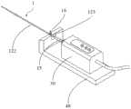
如图1和图2所示,相关技术中,IVUS系统包括血管内超声导管1’和回撤装置30,血管内超声导管1’的近端设置有连接座15’,血管内超声导管1’通过连接座15’与回撤装置30连接,连接座15’上设置有连通阀16’,连通阀16’用于连接注射器50,注射器50用于通过连通阀16’向血管内超声导管1’注液,以冲刷出血管内超声导管1’中的气泡,从而保证超声图像的成像质量。As shown in Figures 1 and 2, in the related art, the IVUS system includes an intravascular ultrasound catheter 1' and a
然而,注射器50在注液的时候容易和回撤装置30干涉,因此需要使用延长管60避免干涉,使用起来比较繁琐、操作不方便。同时,如图2所示,发明人发现,从连接座15’处注入液体需要液体从血管内超声导管1’的近端一直漫延到血管内超声导管1’的远端排出,并且液体从连接座15’进入血管内超声导管1’时需要通过连接座15’的过孔17’,该过孔17’也需要传动轴13’穿过,因此液体需要通过传动轴13’与过孔17’之间的间隙才能进入血管内超声导管1’,而受结构和尺寸限制,该间隙很小,注射器50向血管内超声导管1’内注液冲刷气泡时受到的阻力较大、注液缓慢,因此排出血管内超声导管1’内气泡的效率比较低。However, the
针对上述问题,本申请实施例提供一种血管内超声导管及系统,能够提高注射器50注液排出导管内气泡的效率,避免注射器50与回撤装置30在操作过程中发生干涉。In view of the above problems, the embodiment of the present application provides an intravascular ultrasound catheter and system, which can improve the efficiency of injecting the
以下结合附图详细描述本申请实施例的技术方案。The technical solutions of the embodiments of the present application are described in detail below with reference to the accompanying drawings.
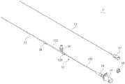
如图3所示,本申请实施例提供一种血管内超声系统,包括回撤装置30、回撤底座40、注射器50和血管内超声导管1。As shown in FIG. 3 , an embodiment of the present application provides an intravascular ultrasound system, including a
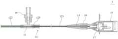
其中,如图4至图8所示,血管内超声导管1包括支撑管11、伸缩管组件12和传动轴13。伸缩管组件12包括内管121、外管122和限位座123,限位座123设于外管122的近端,限位座123内设有与外管122连通的注水腔1231,限位座123套设于内管121并与内管121滑动连接,内管121的远端能够由注水腔1231伸入外管122内,并从外管122内伸出至注水腔1231;限位座123设有与注水腔1231连通的注水口1232。Wherein, as shown in FIGS. 4 to 8 , the
外管122、限位座123和内管121分别套设于支撑管11,支撑管11与外管122的远端连接,传动轴13位于支撑管11内,传动轴13上设有超声检测装置,支撑管11设有注水孔111,注水腔1231通过注水孔111与支撑管11连通,以使从注水口1232注入注水腔1231的液体能够从注水孔111进入所述支撑管11。The
其中,注射器50与注水口1232连通,回撤装置30设于回撤底座40上,回撤装置30与内管121的近端连接,限位座123连接于回撤底座40。回撤装置30用于驱动传动轴13在支撑管11内转动、以及沿支撑管11的轴向移动。Wherein, the
基于上述方案,通过注水口1232向注水腔1231内注入液体,液体可以是生理盐水,注水腔1231通过注水孔111与支撑管11连通,以使从注水口1232注入注水腔1231的液体能够从注水孔111进入支撑管11,进而将支撑管11内的气泡冲刷出去;限位座123设于外管122的近端,相较于从连接座处注入液体的方式,从限位座123注液的位置更接近支撑管11的远端,并且液体从注水腔1231通过注水孔111进入支撑管11的阻力更小,更容易进入支撑管11内,能够更快速地将支撑管11远端的气泡冲刷出去,提高了注射器50注液排出气泡的效率。同时,由于限位座123设于外管122上,注水口1232的位置距离回撤装置30比较远,可以避免注射器50与回撤装置30操作过程中发生干涉,进而避免使用延长管,操作更方便。Based on the above scheme, inject liquid into the
需要说明的是,本申请实施例中,血管内超声导管1的远端指伸入人体内的一端,血管内超声导管1的近端指位于人体外用来与回撤装置30连接的一端,对于血管内超声导管1中的外管122、内管121、支撑管11、传动轴13等零件的远端指靠近血管内超声导管1远端的那一端,相应的其近端指靠近血管内超声导管1近端的那一端。It should be noted that, in the embodiment of the present application, the distal end of the intravascular
具体的,限位座123从上方往下扣,使限位座123固定卡接在回撤底座40上,限制外管122移动,限位座123的形状可为圆柱形或立方体形,回撤底座40上设置由卡接限位座123的卡槽。回撤装置30与内管121的近端及传动轴13的近端连接,用于驱动内管121相对外管122伸缩移动,并驱动传动轴13在支撑管11内转动、以及沿支撑管11的轴向移动。超声检测装置设于传动轴13的远端,在进行超声检测时,回撤装置30通过控制传动轴13运动进而带动超声检测装置运动,具体的,回撤装置30驱动传动轴13回撤时,传动轴13在转动的同时向支撑管11的近端移动,以使超声检测装置在旋转的同时朝向支撑管11的近端移动,从而获取该段血管的超声图像。支撑管11内的气泡会影响超声检测装置的成像,因此需要将超声检测装置检测区域的气泡冲刷出去。回撤装置30还与控制主机通信连接,控制主机可控制回撤装置30工作,控制主机还可与超声检测装置通信连接,用于接收超声检测装置的检测信号,并根据检测信号生成血管的超声图像。Specifically, the
图4示出的是内管121相对外管122缩回时血管内超声导管1的结构示意图,即内管121伸入至外管122内时的状态;图5示出的是内管121相对外管122伸出时血管内超声导管1的结构示意图。在进行超声检测时,回撤装置30会驱动内管121逐渐伸出外管122,即传动轴13远端的超声检测装置从远端向近端移动。What Fig. 4 shows is the structural diagram of the intravascular
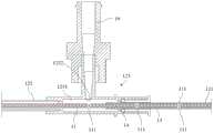
如图8所示,在本实施例中,内管121的远端伸出外管122的近端后位于注水腔1231内,内管121远端的直径大于注水腔1231右侧的开孔,这样能够限制内管121的远端从注水腔1231的右侧移出注水腔1231,限位座123的左侧与外管122的近端固定连接,外管122的近端与注水腔1231连通,内管121的远端可穿过注水腔1231的左侧并伸入外管122内。在进行注水冲刷时,可将内管121的远端移动至注水腔1231内的右侧区域,可使从注水口1232注入注水腔1231内的液体直接进入支撑管11内。As shown in Figure 8, in this embodiment, the distal end of the
进一步的,为了更加便于注水腔1231内的液体进入支撑管11内,在一些实施例中,注水孔111位于注水腔1231内并与注水口1232相对设置。具体的,如图8所示,注水孔111位于支撑管11在注水腔1231中的管壁上,且注水孔111正对注水口1232,这样,从注水口1232注入的液体能够更快地从注水孔111进入支撑管11内,使液体更快速地将支撑管11远端的气泡从支撑管11远端开设的出水口排出,提高气泡冲刷的效率。Further, in order to make it easier for the liquid in the
进一步的,为了提高注水的效率,限位座123上的注水口1232可以为多个,即可以同时连接多个注射器50,多个注射器50同时往限位座123里面注水,保证足够的进水量可以冲刷管腔内的气泡,而不需要单个注射器50多次注水。Further, in order to improve the efficiency of water injection, there can be multiple
如图9所示,在一些实施例中,注水孔111具有多个,多个注水孔111沿支撑管11的轴向间隔设置,这样能够进一步提高注水冲刷气泡的而效率。其中,可保证至少一个注水孔111位于注水腔1231内,其他注水孔111可位于注水腔1231的右侧,即内管121所在的区域,或者注水孔111还可位于注水腔1231的左侧,即外管122所在的区域。As shown in FIG. 9 , in some embodiments, there are multiple water injection holes 111 , and the multiple water injection holes 111 are arranged at intervals along the axial direction of the
如图10所示,在一些实施例中,支撑管11上设有沿支撑管11的轴向间隔设置的多个注水孔111组,每个注水孔111组均包括多个绕支撑管11的轴线周向设置的注水孔111,以进一步提高注水冲刷气泡的效率。As shown in Figure 10, in some embodiments, the
如图8至图10所示,本申请实施例的血管内超声导管1还包括设于内管121与限位座123之间的密封件14,密封件14用于防止注水腔1231内的液体从内管121与限位座123之间的间隙溢出。As shown in FIGS. 8 to 10 , the
具体的,密封件14可为密封圈,限位座123上设有密封槽,密封圈设于密封槽内,密封圈套设于内管121,这样使内管121能够相对限位座123滑动的同时保证内管121与限位座123之间的密封性。Specifically, the sealing
如图4至图8所示,本申请实施例的血管内超声导管1还包括连接座15和连通阀16,连接座15与内管121的近端连接,连通阀16与注水口1232连通。具体的,连接座15与内管121的近端固定连接,内管121通过连接座15与回撤装置30连接,注射器50通过连通阀16向注水腔1231内注入液体,连通阀16可与限位座123一体成型。其中,连通阀16为单向单通阀,保证注水腔1231的液体不会从注水口1232流出。As shown in FIG. 4 to FIG. 8 , the
如图11所示,在一些实施例中,连通阀16为单向三通阀,可以同时连接两个注射器50,提高注水效率。As shown in FIG. 11 , in some embodiments, the
如图6和图7所示,本申请实施例的血管内超声导管1还包括支撑座17,支撑座17与传动轴13的近端连接,连接座15套设于支撑座17并与支撑座17转动连接。具体的,回撤装置30通过支撑座17控制传动轴13转动和移动,支撑座17与传动轴13固定连接,传动轴13可以是海波管结构或弹簧结构等。连接座15的内腔还设有卡圈18,卡圈18抵接在支撑座17的右侧,防止支撑座17从连接座15内脱出。As shown in Figures 6 and 7, the
如图4至图6所示,本申请实施例的血管内超声导管1还包括第一去应力管19和第二去应力管20,第一去应力管19套设于内管121与连接座15的连接处,第二去应力管20套设于外管122与支撑管11的连接处。具体的,内管121的近端与连接座15固定连接,外管122的远端与支撑管11固定连接,第一去应力管19用于防止内管121与连接座15之间因应力集中发生弯折,第二去应力管20用于防止外管122与支撑管11之间因应力集中发生弯折。第一去应力管19和第二去应力管20均可采用较软的树脂材料制成。As shown in Figures 4 to 6, the intravascular
本申请实施例提供的血管内超声系统的工作原理如下:The working principle of the intravascular ultrasound system provided in the embodiment of the present application is as follows:
1、经皮穿刺桡动脉,置入指引导管,抵达冠脉口。1. Percutaneously puncture the radial artery, insert a guiding catheter, and reach the coronary ostia.
2、使用DSA,沿着指引导管打入造影剂,找到目标位置,进入导丝抵达目标位置。2. Using DSA, inject contrast agent along the guiding catheter, find the target position, and enter the guide wire to reach the target position.
3、对血管内超声导管1打水冲刷,将导管内气体排出。3. Flush the
4、血管内超声导管1沿着导丝进入目标位置,控制主机发射信号,超声检测装置开始原地旋转。4. The
5、血管内超声导管1回撤获取整段的血管内超声图像,给与术者影像学的指导。5. The
6、血管内超声导管1退出体外,手术结束。6. The
以上已经描述了本申请的各实施例,上述说明是示例性的,并非穷尽性的,并且也不限于所披露的各实施例。在不偏离所说明的各实施例的范围和精神的情况下,对于本技术领域的普通技术人员来说许多修改和变更都是显而易见的。本文中所用术语的选择,旨在最好地解释各实施例的原理、实际应用或对市场中的技术的改进,或者使本技术领域的其他普通技术人员能理解本文披露的各实施例。Having described various embodiments of the present application above, the foregoing description is exemplary, not exhaustive, and is not limited to the disclosed embodiments. Many modifications and alterations will be apparent to those of ordinary skill in the art without departing from the scope and spirit of the described embodiments. The terminology used herein is chosen to best explain the principle of each embodiment, practical application or improvement of technology in the market, or to enable other ordinary skilled in the art to understand each embodiment disclosed herein.
Claims (10)
Priority Applications (1)
| Application Number | Priority Date | Filing Date | Title |
|---|---|---|---|
| CN202310320702.7ACN116158785B (en) | 2023-03-23 | 2023-03-23 | Intravascular ultrasound catheter and system |
Applications Claiming Priority (1)
| Application Number | Priority Date | Filing Date | Title |
|---|---|---|---|
| CN202310320702.7ACN116158785B (en) | 2023-03-23 | 2023-03-23 | Intravascular ultrasound catheter and system |
Publications (2)
| Publication Number | Publication Date |
|---|---|
| CN116158785Atrue CN116158785A (en) | 2023-05-26 |
| CN116158785B CN116158785B (en) | 2025-09-16 |
Family
ID=86420222
Family Applications (1)
| Application Number | Title | Priority Date | Filing Date |
|---|---|---|---|
| CN202310320702.7AActiveCN116158785B (en) | 2023-03-23 | 2023-03-23 | Intravascular ultrasound catheter and system |
Country Status (1)
| Country | Link |
|---|---|
| CN (1) | CN116158785B (en) |
Cited By (2)
| Publication number | Priority date | Publication date | Assignee | Title |
|---|---|---|---|---|
| CN116831631A (en)* | 2023-07-26 | 2023-10-03 | 深圳皓影医疗科技有限公司 | Intravascular ultrasonic diagnosis catheter and telescopic assembly thereof |
| CN117084721A (en)* | 2023-09-13 | 2023-11-21 | 上海博动医疗科技股份有限公司 | Ultrasonic catheter structure |
Citations (5)
| Publication number | Priority date | Publication date | Assignee | Title |
|---|---|---|---|---|
| CN109528236A (en)* | 2018-12-31 | 2019-03-29 | 深圳北芯生命科技有限公司 | Injection device for intravascular ultrasound catheter |
| US20210052168A1 (en)* | 2019-08-21 | 2021-02-25 | Corflow Therapeutics Ag | Controlled-Flow Infusion Catheter and Method |
| CN214966546U (en)* | 2021-01-29 | 2021-12-03 | 西安外科医学科技有限公司 | Telescopic bipolar scalpel |
| CN218247247U (en)* | 2022-08-02 | 2023-01-10 | 深圳北芯生命科技股份有限公司 | Connecting seat and intravascular ultrasound catheter |
| CN218922634U (en)* | 2022-08-24 | 2023-04-28 | 深圳北芯生命科技股份有限公司 | Intravascular interventional catheter |
- 2023
- 2023-03-23CNCN202310320702.7Apatent/CN116158785B/enactiveActive
Patent Citations (5)
| Publication number | Priority date | Publication date | Assignee | Title |
|---|---|---|---|---|
| CN109528236A (en)* | 2018-12-31 | 2019-03-29 | 深圳北芯生命科技有限公司 | Injection device for intravascular ultrasound catheter |
| US20210052168A1 (en)* | 2019-08-21 | 2021-02-25 | Corflow Therapeutics Ag | Controlled-Flow Infusion Catheter and Method |
| CN214966546U (en)* | 2021-01-29 | 2021-12-03 | 西安外科医学科技有限公司 | Telescopic bipolar scalpel |
| CN218247247U (en)* | 2022-08-02 | 2023-01-10 | 深圳北芯生命科技股份有限公司 | Connecting seat and intravascular ultrasound catheter |
| CN218922634U (en)* | 2022-08-24 | 2023-04-28 | 深圳北芯生命科技股份有限公司 | Intravascular interventional catheter |
Cited By (2)
| Publication number | Priority date | Publication date | Assignee | Title |
|---|---|---|---|---|
| CN116831631A (en)* | 2023-07-26 | 2023-10-03 | 深圳皓影医疗科技有限公司 | Intravascular ultrasonic diagnosis catheter and telescopic assembly thereof |
| CN117084721A (en)* | 2023-09-13 | 2023-11-21 | 上海博动医疗科技股份有限公司 | Ultrasonic catheter structure |
Also Published As
| Publication number | Publication date |
|---|---|
| CN116158785B (en) | 2025-09-16 |
Similar Documents
| Publication | Publication Date | Title |
|---|---|---|
| JP5399301B2 (en) | catheter | |
| US4024873A (en) | Balloon catheter assembly | |
| CN114259627B (en) | Interventional injection device and interventional injection system | |
| US11317890B2 (en) | Catheter and imaging apparatus for diagnosis | |
| JP2011152274A (en) | In-vivo diagnostic apparatus and control method for the same | |
| CN218247247U (en) | Connecting seat and intravascular ultrasound catheter | |
| CN116158785A (en) | Intravascular ultrasound catheters and systems | |
| CN212546924U (en) | Little pipe pressure measurement device | |
| CN218922634U (en) | Intravascular interventional catheter | |
| CN110420376B (en) | Coil pipe for drug balloon catheter and drug balloon catheter device | |
| JP2001245886A (en) | Ultrasonic echo catheter within blood vessel | |
| CN114225189B (en) | An intraocular imaging balloon catheter | |
| CN109528236B (en) | Injection device for intravascular ultrasound catheter | |
| CN117504632A (en) | Preparation method of isolated bubble suspension for TCD foaming test | |
| CN107518876B (en) | Washing-free fully-sealed miniature Optical Coherence Tomography (OCT) imaging catheter | |
| WO2023179316A1 (en) | Medical catheter and system | |
| CN115317024A (en) | A Novel Intravascular Ultrasound Diagnostic Catheter | |
| CN116135156A (en) | Intravascular ultrasonic catheter, vascular ultrasonic detection system and control method | |
| JP4614265B2 (en) | In vivo observation catheter | |
| CN119185738B (en) | Multifunctional catheter | |
| JPWO2017149974A1 (en) | Medical device | |
| CN222055450U (en) | Intravascular ultrasound device | |
| CN221535325U (en) | A diagnostic catheter | |
| CN213075610U (en) | Sealed OCT imaging catheter | |
| CN111938788B (en) | A kind of atrial septal puncture component |
Legal Events
| Date | Code | Title | Description |
|---|---|---|---|
| PB01 | Publication | ||
| PB01 | Publication | ||
| SE01 | Entry into force of request for substantive examination | ||
| SE01 | Entry into force of request for substantive examination | ||
| GR01 | Patent grant | ||
| GR01 | Patent grant |