CN116158687A - Vacuum cleaner with auxiliary head - Google Patents
Vacuum cleaner with auxiliary headDownload PDFInfo
- Publication number
- CN116158687A CN116158687ACN202211491766.5ACN202211491766ACN116158687ACN 116158687 ACN116158687 ACN 116158687ACN 202211491766 ACN202211491766 ACN 202211491766ACN 116158687 ACN116158687 ACN 116158687A
- Authority
- CN
- China
- Prior art keywords
- suction head
- vacuum cleaner
- cleaner housing
- cleaner
- housing
- Prior art date
- Legal status (The legal status is an assumption and is not a legal conclusion. Google has not performed a legal analysis and makes no representation as to the accuracy of the status listed.)
- Pending
Links
- 238000004140cleaningMethods0.000claimsdescription25
- 238000000926separation methodMethods0.000claimsdescription14
- 239000002699waste materialSubstances0.000claimsdescription14
- 238000011144upstream manufacturingMethods0.000claimsdescription3
- 230000008878couplingEffects0.000description12
- 238000010168coupling processMethods0.000description12
- 238000005859coupling reactionMethods0.000description12
- 244000007853Sarothamnus scopariusSpecies0.000description3
- 238000011086high cleaningMethods0.000description2
- 238000000034methodMethods0.000description2
- 230000004308accommodationEffects0.000description1
- 238000006073displacement reactionMethods0.000description1
- 239000000428dustSubstances0.000description1
- 230000005484gravityEffects0.000description1
- 230000005415magnetizationEffects0.000description1
- 238000012986modificationMethods0.000description1
- 230000004048modificationEffects0.000description1
- 238000006467substitution reactionMethods0.000description1
Images


Classifications
- A—HUMAN NECESSITIES
- A47—FURNITURE; DOMESTIC ARTICLES OR APPLIANCES; COFFEE MILLS; SPICE MILLS; SUCTION CLEANERS IN GENERAL
- A47L—DOMESTIC WASHING OR CLEANING; SUCTION CLEANERS IN GENERAL
- A47L5/00—Structural features of suction cleaners
- A47L5/12—Structural features of suction cleaners with power-driven air-pumps or air-compressors, e.g. driven by motor vehicle engine vacuum
- A47L5/22—Structural features of suction cleaners with power-driven air-pumps or air-compressors, e.g. driven by motor vehicle engine vacuum with rotary fans
- A47L5/24—Hand-supported suction cleaners
- A—HUMAN NECESSITIES
- A47—FURNITURE; DOMESTIC ARTICLES OR APPLIANCES; COFFEE MILLS; SPICE MILLS; SUCTION CLEANERS IN GENERAL
- A47L—DOMESTIC WASHING OR CLEANING; SUCTION CLEANERS IN GENERAL
- A47L5/00—Structural features of suction cleaners
- A47L5/12—Structural features of suction cleaners with power-driven air-pumps or air-compressors, e.g. driven by motor vehicle engine vacuum
- A47L5/22—Structural features of suction cleaners with power-driven air-pumps or air-compressors, e.g. driven by motor vehicle engine vacuum with rotary fans
- A47L5/225—Convertible suction cleaners, i.e. convertible between different types thereof, e.g. from upright suction cleaners to sledge-type suction cleaners
- A—HUMAN NECESSITIES
- A47—FURNITURE; DOMESTIC ARTICLES OR APPLIANCES; COFFEE MILLS; SPICE MILLS; SUCTION CLEANERS IN GENERAL
- A47L—DOMESTIC WASHING OR CLEANING; SUCTION CLEANERS IN GENERAL
- A47L5/00—Structural features of suction cleaners
- A47L5/12—Structural features of suction cleaners with power-driven air-pumps or air-compressors, e.g. driven by motor vehicle engine vacuum
- A47L5/22—Structural features of suction cleaners with power-driven air-pumps or air-compressors, e.g. driven by motor vehicle engine vacuum with rotary fans
- A47L5/28—Suction cleaners with handles and nozzles fixed on the casings, e.g. wheeled suction cleaners with steering handle
- A—HUMAN NECESSITIES
- A47—FURNITURE; DOMESTIC ARTICLES OR APPLIANCES; COFFEE MILLS; SPICE MILLS; SUCTION CLEANERS IN GENERAL
- A47L—DOMESTIC WASHING OR CLEANING; SUCTION CLEANERS IN GENERAL
- A47L5/00—Structural features of suction cleaners
- A47L5/12—Structural features of suction cleaners with power-driven air-pumps or air-compressors, e.g. driven by motor vehicle engine vacuum
- A47L5/22—Structural features of suction cleaners with power-driven air-pumps or air-compressors, e.g. driven by motor vehicle engine vacuum with rotary fans
- A47L5/36—Suction cleaners with hose between nozzle and casing; Suction cleaners for fixing on staircases; Suction cleaners for carrying on the back
- A47L5/365—Suction cleaners with hose between nozzle and casing; Suction cleaners for fixing on staircases; Suction cleaners for carrying on the back of the vertical type, e.g. tank or bucket type
- A—HUMAN NECESSITIES
- A47—FURNITURE; DOMESTIC ARTICLES OR APPLIANCES; COFFEE MILLS; SPICE MILLS; SUCTION CLEANERS IN GENERAL
- A47L—DOMESTIC WASHING OR CLEANING; SUCTION CLEANERS IN GENERAL
- A47L9/00—Details or accessories of suction cleaners, e.g. mechanical means for controlling the suction or for effecting pulsating action; Storing devices specially adapted to suction cleaners or parts thereof; Carrying-vehicles specially adapted for suction cleaners
- A47L9/02—Nozzles
- A—HUMAN NECESSITIES
- A47—FURNITURE; DOMESTIC ARTICLES OR APPLIANCES; COFFEE MILLS; SPICE MILLS; SUCTION CLEANERS IN GENERAL
- A47L—DOMESTIC WASHING OR CLEANING; SUCTION CLEANERS IN GENERAL
- A47L9/00—Details or accessories of suction cleaners, e.g. mechanical means for controlling the suction or for effecting pulsating action; Storing devices specially adapted to suction cleaners or parts thereof; Carrying-vehicles specially adapted for suction cleaners
- A47L9/10—Filters; Dust separators; Dust removal; Automatic exchange of filters
- A47L9/16—Arrangement or disposition of cyclones or other devices with centrifugal action
- A—HUMAN NECESSITIES
- A47—FURNITURE; DOMESTIC ARTICLES OR APPLIANCES; COFFEE MILLS; SPICE MILLS; SUCTION CLEANERS IN GENERAL
- A47L—DOMESTIC WASHING OR CLEANING; SUCTION CLEANERS IN GENERAL
- A47L9/00—Details or accessories of suction cleaners, e.g. mechanical means for controlling the suction or for effecting pulsating action; Storing devices specially adapted to suction cleaners or parts thereof; Carrying-vehicles specially adapted for suction cleaners
- A47L9/32—Handles
- A47L9/322—Handles for hand-supported suction cleaners
Landscapes
- Engineering & Computer Science (AREA)
- Mechanical Engineering (AREA)
- Electric Vacuum Cleaner (AREA)
- Nozzles For Electric Vacuum Cleaners (AREA)
- Electric Suction Cleaners (AREA)
Abstract
Translated fromChinese
Description
Translated fromChinese技术领域technical field
本发明尤其涉及扫把式家用吸尘器,其允许抽吸待清洁表面上的灰尘和废物,所述待清洁表面可以是瓷砖、拼花地板、层压板、地垫或地毯。The invention relates in particular to a household vacuum cleaner of the broom type, which allows the suction of dust and waste from the surface to be cleaned, which may be tiles, parquet, laminate, rugs or carpets.
背景技术Background technique
扫把式吸尘器以已知方式包括:Broom vacuum cleaners include in a known manner:
-主体,其配置成搁放在待清洁的地板上并在待清洁的地板上滚动,所述主体包括吸尘器壳体和安装成能相对于吸尘器壳体旋转移动的第一和第二主轮,- a body configured to rest on and roll on the floor to be cleaned, said body comprising a cleaner housing and first and second main wheels mounted for rotational movement relative to the cleaner housing,
-吸头,吸尘器可以通过所述吸头抽吸外部空气,- a suction head through which the vacuum cleaner can suck in external air,
-至少一个排气口,经由吸尘器清洁的空气可以通过所述排气口离开吸尘器,- at least one exhaust opening through which air cleaned via the vacuum cleaner can leave the vacuum cleaner,
-空气回路,其在吸头和至少一个排气口之间延伸,- an air circuit extending between the suction head and at least one exhaust port,
-抽吸电机,其容纳在吸尘器壳体中并且设置在空气回路上方,所述抽吸电机配置成在空气回路中产生气流,以及- a suction motor housed in the cleaner housing and arranged above the air circuit, said suction motor being configured to generate an air flow in the air circuit, and
-握柄,其机械地连接到吸尘器壳体。- A handle mechanically connected to the cleaner housing.
上述吸尘器的这种配置为吸尘器提供了良好的可操作性,便于使用者对其进行使用。Such a configuration of the above-mentioned vacuum cleaner provides good operability for the vacuum cleaner, and is convenient for users to use it.
然而,上述扫把式吸尘器进入某些待清洁区域可能被证实是很复杂的,甚至是不可能的,因为一方面,这种吸尘器的主体在高度上的尺寸相对较大(特别是因为抽吸电机集成在吸尘器壳体中),另一方面,这种吸尘器的吸头的横向尺寸也相对较大。However, the access of the aforementioned broom-type vacuum cleaners to certain areas to be cleaned may prove to be complicated, or even impossible, because on the one hand, the body of such vacuum cleaners is relatively large in height (especially because the suction motor integrated in the vacuum cleaner housing), on the other hand, the lateral dimension of the suction head of this vacuum cleaner is also relatively large.
发明内容Contents of the invention
本发明的目标是弥补这些缺点。The aim of the present invention is to remedy these disadvantages.
本发明的基本技术问题尤其在于提供一种结构简单、经济且可靠、同时具有高清洁性能的吸尘器。The technical problem underlying the invention is, inter alia, to provide a vacuum cleaner that is structurally simple, economical and reliable, and at the same time has a high cleaning performance.
为此,本发明的目的是提供一种吸尘器,包括:To this end, the object of the present invention is to provide a vacuum cleaner comprising:
-主体,其配置成搁放在待清洁的地板上并在待清洁的地板上滚动,所述主体包括设有壳体的外表面的吸尘器壳体,以及安装成能相对于吸尘器壳体旋转移动的第一和第二主轮,- a body configured to rest on and roll on the floor to be cleaned, said body comprising a cleaner housing provided with an outer surface of the housing and mounted for rotational movement relative to the cleaner housing the first and second main wheels,
-主吸头,其机械地连结到吸尘器壳体,吸尘器能够通过所述主吸头抽吸外部空气,- a main suction head mechanically linked to the vacuum cleaner housing, through which the vacuum cleaner is able to suck in external air,
-至少一个排气口,经由吸尘器清洁的空气能够通过所述排气口离开吸尘器,- at least one exhaust opening through which air cleaned via the vacuum cleaner can leave the vacuum cleaner,
-空气回路,其在主吸头和至少一个排气口之间延伸,- an air circuit extending between the main suction head and at least one exhaust port,
-抽吸电机,其容纳在吸尘器壳体中并且设置在空气回路上方,所述抽吸电机配置成在空气回路中产生气流,以及- a suction motor housed in the cleaner housing and arranged above the air circuit, said suction motor being configured to generate an air flow in the air circuit, and
-握柄,其配置成机械地连接到吸尘器壳体并且部分地界定空气回路。- A handle configured to be mechanically connected to the cleaner housing and partially delimits the air circuit.
握柄包括远端部,所述远端部配有副吸头,所述副吸头可拆卸地紧固到吸尘器壳体,并且当副吸头紧固在吸尘器壳体上时,以及当副吸头从吸尘器外壳上分离时,副吸头流体地连结到抽吸电机,副吸头配置成当副吸头紧固到吸尘器壳体上时(例如密封地)流体地连结到主吸头,并且副吸头配置成当副吸头从吸尘器壳体上分离时清洁表面。The handle includes a distal portion equipped with an auxiliary suction head detachably fastened to the vacuum cleaner housing, and when the auxiliary suction head is fastened to the vacuum cleaner housing, and when the auxiliary suction head When the suction head is separated from the cleaner housing, the auxiliary suction head is fluidly connected to the suction motor, the auxiliary suction head is configured to be fluidly connected (eg sealingly) to the main suction head when the auxiliary suction head is fastened to the cleaner housing, And the sub-head is configured to clean the surface when the sub-head is detached from the cleaner housing.
根据本发明的吸尘器的这种配置允许使用者将副吸头从吸尘器壳体分离(从而将吸头从吸尘器壳体移开一段距离),然后用副吸头对主吸头无法进入的待清洁区域(例如,位于天花板处或低矮家具下方的区域)进行吸尘。This configuration of the vacuum cleaner according to the present invention allows the user to separate the auxiliary suction head from the vacuum cleaner housing (thereby moving the suction head away from the vacuum cleaner housing for a certain distance), and then use the auxiliary suction head to clean the parts that cannot be accessed by the main suction head. Vacuum areas such as those located at the ceiling or under low furniture.
当使用者希望清洁主吸头可以进入的区域时,使用者将副吸头重新连接到吸尘器壳体,并用主吸头对所述待清洁区域进行吸尘。When the user wishes to clean the area that the main suction head can enter, the user reconnects the auxiliary suction head to the vacuum cleaner housing, and uses the main suction head to vacuum the area to be cleaned.
因此,根据本发明的吸尘器具有高清洁性能,同时结构简单、经济且可靠。Thus, the vacuum cleaner according to the invention has a high cleaning performance while being structurally simple, economical and reliable.
所述吸尘器还可以具有以下一个或多个单独或组合的特征。The vacuum cleaner may also have one or more of the following features alone or in combination.
根据本发明的实施例,副吸头配置成当副吸头紧固到吸尘器外壳上时相对于吸尘器壳体固定不动。According to an embodiment of the present invention, the auxiliary suction head is configured to be fixed relative to the cleaner housing when the auxiliary suction head is fastened to the cleaner housing.
根据本发明的实施例,副吸头的侧向或横向尺寸小于主吸头的侧向或横向尺寸。这些设置允许确保利用副吸头对宽度较小的待清洁区域进行最佳的清洁。According to an embodiment of the present invention, the lateral or transverse dimension of the auxiliary tip is smaller than the lateral or transverse dimension of the main tip. These settings make it possible to ensure optimum cleaning of areas to be cleaned with a smaller width with the sub-tip.
根据本发明的实施例,主吸头包括底板,底板设有下表面和在下表面上开口的抽吸腔。According to an embodiment of the present invention, the main suction head includes a bottom plate provided with a lower surface and a suction cavity opened on the lower surface.
根据本发明的实施例,吸尘器包括锁定构件,例如锁定指状件,其可在锁定位置和释放位置之间移动,例如枢转地安装,在锁定位置,锁定构件将副吸头锁定在吸尘器壳体上并防止副吸头从吸尘器壳体上分离,在释放位置,锁定构件释放副吸头并准许副吸头从吸尘器壳体上分离。有利的是,锁定构件设置在吸尘器壳体的上部。这种锁定构件避免了会干扰吸尘器的使用的副吸头的不合时宜的分离。According to an embodiment of the invention, the vacuum cleaner comprises a locking member, such as a locking finger, which is movable, such as pivotally mounted, between a locking position and a release position in which the locking member locks the auxiliary head to the vacuum cleaner housing In the release position, the locking member releases the auxiliary nozzle and allows the auxiliary nozzle to be separated from the cleaner housing. Advantageously, the locking member is arranged in the upper part of the cleaner housing. Such a locking member avoids untimely separation of the auxiliary head which would interfere with the use of the vacuum cleaner.
根据本发明的实施例,副吸头包括锁定元件,如锁定凹部,所述锁定元件配置成当锁定构件处于锁定位置时与锁定构件配合。According to an embodiment of the invention, the sub-tip comprises a locking element, such as a locking recess, configured to cooperate with the locking member when the locking member is in the locking position.
根据本发明的实施例,吸尘器包括偏置构件,所述偏置构件配置成将锁定构件向锁定位置偏置。这些设置允许在副吸头连接到吸尘器壳体时确保锁定构件向锁定位置自动移动。According to an embodiment of the present invention, the cleaner includes a biasing member configured to bias the locking member towards the locked position. These arrangements allow to ensure automatic movement of the locking member towards the locked position when the auxiliary head is connected to the cleaner housing.
根据本发明的实施例,吸尘器包括解锁构件,例如解锁按钮,所述解锁构件配置成将锁定构件向释放位置移动。有利的是,解锁构件设置在吸尘器壳体上。这种解锁构件的存在允许使用者容易将锁定构件移动到释放位置。According to an embodiment of the invention, the cleaner comprises an unlocking member, such as an unlocking button, configured to move the locking member towards the release position. Advantageously, the unlocking member is arranged on the vacuum cleaner housing. The presence of such an unlocking member allows the user to easily move the locking member to the release position.
根据本发明的实施例,副吸头包括紧固到握柄上的紧固部分和机械地连结到紧固部分的清洁部分。According to an embodiment of the present invention, the sub-tip includes a fastening portion fastened to the handle and a cleaning portion mechanically coupled to the fastening portion.
根据本发明的实施例,紧固部分是管状的并且套配有握柄。According to an embodiment of the invention, the fastening part is tubular and fitted with a handle.
根据本发明的实施例,握柄包括细长的并且具有中心纵轴的手柄部分,紧固部分紧固到手柄部分上,并且清洁部分安装成能绕横向于手柄部分的中心纵轴延伸的枢轴相对于紧固部分枢转。这些设置允许便于借助副吸头进行清洁操作。According to an embodiment of the invention, the handle comprises an elongated handle portion having a central longitudinal axis, the fastening portion is fastened to the handle portion, and the cleaning portion is mounted as a pivot extending transversely to the central longitudinal axis of the handle portion. The shaft pivots relative to the fastening portion. These settings allow to facilitate cleaning operations with the aid of the sub-tip.
根据本发明的实施例,锁定元件设置在清洁部分上。According to an embodiment of the invention, the locking element is arranged on the cleaning part.
根据本发明的实施例,吸尘器包括锁紧装置,所述锁紧装置配置成当副吸头紧固到吸尘器壳体上时防止清洁部分绕枢轴枢转。这种锁紧装置的存在确保了当握柄向后或向前倾斜时握柄和吸尘器壳体的同时倾斜。According to an embodiment of the present invention, the cleaner includes locking means configured to prevent the cleaning part from pivoting about the pivot when the auxiliary head is fastened to the cleaner housing. The presence of such locking means ensures simultaneous tilting of the handle and the cleaner housing when the handle is tilted backwards or forwards.
根据本发明的实施例,吸尘器壳体包括连接套筒,当副吸头紧固到吸尘器壳体上时,副吸头连接在所述连接套筒上。有利的是,连接套筒至少部分地形成锁紧装置。According to an embodiment of the present invention, the vacuum cleaner housing includes a connection sleeve on which the auxiliary suction head is connected when the auxiliary suction head is fastened to the vacuum cleaner housing. It is advantageous if the connecting sleeve at least partially forms the locking device.
根据本发明的实施例,紧固部分包括内导管,所述内导管配置成当副吸头紧固到吸尘器壳体上时流体地连结到所述连接套筒。According to an embodiment of the invention, the fastening part comprises an inner conduit configured to be fluidly coupled to said connection sleeve when the auxiliary suction head is fastened to the cleaner housing.
根据本发明的实施例,内导管包括管状的远端部,当副吸头紧固到吸尘器壳体上时,所述远端部上套配有连接套筒。According to an embodiment of the present invention, the inner conduit comprises a tubular distal end, which is covered with a connecting sleeve when the auxiliary suction head is fastened to the vacuum cleaner housing.
根据本发明的实施例,连接套筒从壳体的外表面突出。According to an embodiment of the present invention, the connection sleeve protrudes from the outer surface of the housing.
根据本发明的实施例,吸尘器壳体包括容纳凹部,所述容纳凹部在壳体的外表面中开口,并且配置成当副吸头紧固到吸尘器壳体时至少部分地容纳副吸头。According to an embodiment of the present invention, the cleaner housing includes an accommodating recess opening in an outer surface of the housing and configured to at least partially accommodate the sub-head when it is fastened to the cleaner housing.
根据本发明的实施例,容纳凹部配置成至少部分地容纳清洁部分。According to an embodiment of the invention, the accommodation recess is configured to at least partially accommodate the cleaning portion.
根据本发明的实施例,连接套筒从容纳凹部的底壁延伸。According to an embodiment of the present invention, the connection sleeve extends from the bottom wall of the receiving recess.
根据本发明的实施例,吸尘器包括柔性联接导管,所述联接导管位于吸尘器壳体内,并且将主吸头流体地连接到连接套筒。According to an embodiment of the invention, the vacuum cleaner comprises a flexible coupling conduit located in the vacuum cleaner housing and fluidly connecting the main suction head to the connection sleeve.
根据本发明的实施例,副吸头包括设置在紧固部分和清洁部分之间的中间部分,清洁部分安装成能绕枢轴相对于中间部分枢转,并且紧固部分安装成能绕基本垂直于所述枢轴的附加枢轴相对于中间部分枢转。这些设置允许便于借助握柄在待清洁表面上移动主体。According to an embodiment of the present invention, the auxiliary suction head includes an intermediate portion disposed between the fastening portion and the cleaning portion, the cleaning portion is installed to be pivotable about a pivot axis relative to the intermediate portion, and the fastening portion is installed to be able to rotate about a substantially vertical An additional pivot to said pivot pivots relative to the middle portion. These arrangements allow easy movement of the main body over the surface to be cleaned by means of the handle.
根据本发明的实施例,附加枢轴与内导管的远端部的中心纵轴基本共线。According to an embodiment of the invention, the additional pivot is substantially co-linear with the central longitudinal axis of the distal end of the inner catheter.
根据本发明的实施例,清洁部分具有当副吸头紧固到吸尘器壳体上时与壳体的外表面基本齐平的外表面。当副吸头紧固到吸尘器壳体上时,这些设置允许保持副吸头的完整性,更尤其是清洁部分的完整性。According to an embodiment of the present invention, the cleaning part has an outer surface substantially flush with an outer surface of the housing when the sub-head is fastened to the cleaner housing. These arrangements allow maintaining the integrity of the sub-head, more particularly the integrity of the cleaning part, when it is fastened to the cleaner housing.
根据本发明的实施例,吸尘器包括抽吸导管,所述抽吸导管例如是柔性的,部分地界定空气回路,所述抽吸导管包括第一端部,所述第一端部机械地连接到吸尘器壳体,并且流体地连结到抽吸电机,以及第二端部,所述第二端部机械地连接到握柄并且流体地连结到握柄,例如到握柄的近端部。According to an embodiment of the invention, the vacuum cleaner comprises a suction duct, for example flexible, partially delimiting an air circuit, said suction duct comprising a first end mechanically connected to The cleaner housing, and fluidly coupled to the suction motor, and a second end mechanically coupled to the handle and fluidly coupled to the handle, eg, to a proximal end of the handle.
根据本发明的实施例,主吸头安装成绕横向铰接轴并且在主吸头靠近吸尘器壳体前边缘的缩回位置和主吸头远离吸尘器壳体前边缘的展开位置之间铰接在吸尘器壳体上。根据本发明的吸尘器的这种配置允许主吸头到达主体无法进入的区域(由于主体特别装备有抽吸电机,所以主体的高度大于主吸头的高度),例如位于家具下面的区域。According to an embodiment of the invention, the main suction head is mounted so as to be hinged to the cleaner housing about a transverse hinge axis and between a retracted position of the main suction head close to the front edge of the cleaner housing and a deployed position of the main suction head away from the front edge of the cleaner housing. physically. This configuration of the vacuum cleaner according to the invention allows the main suction head to reach areas inaccessible to the main body (the height of the main body is greater than that of the main suction head since the main body is specially equipped with a suction motor), such as areas located under furniture.
根据本发明的实施例,吸尘器配置成使得握柄和吸尘器壳体从吸尘器的预定操作位置并绕第一和第二主轮的旋转轴的向后倾斜引起主吸头向展开位置的移动,并且使得握柄和吸尘器壳体朝向吸尘器的预定操作位置并绕第一和第二主轮的旋转轴的向前倾斜引起主吸头向缩回位置的移动。根据本发明的吸尘器的这种配置允许主吸头容易在缩回位置和展开位置之间移动。According to an embodiment of the invention, the cleaner is configured such that rearward tilting of the handle and cleaner housing from a predetermined operating position of the cleaner about the rotational axis of the first and second main wheels causes movement of the main suction head to the deployed position, and Forward tilting of the handle and cleaner housing towards a predetermined operating position of the cleaner about the rotational axes of the first and second main wheels causes movement of the main suction head to the retracted position. This configuration of the vacuum cleaner according to the invention allows easy movement of the main suction head between the retracted position and the extended position.
根据本发明的实施例,预定操作位置对应于吸尘器的存放位置,也称为停放位置,在所述位置,第一和第二主轮搁放在待清洁的地板上,握柄基本竖直延伸。According to an embodiment of the invention, the predetermined operating position corresponds to a storage position of the vacuum cleaner, also referred to as a parked position, in which the first and second main wheels rest on the floor to be cleaned and the handle extends substantially vertically .
根据本发明的实施例,当副吸头紧固到吸尘器壳体上时,枢轴基本平行于横向铰接轴延伸。副吸头的这种配置允许便于用副吸头进行清洁操作。According to an embodiment of the invention, when the auxiliary suction head is fastened to the cleaner housing, the pivot axis extends substantially parallel to the transverse hinge axis. This configuration of the sub-tip allows for easy cleaning operations with the sub-tip.
根据本发明的实施例,吸尘器包括可充电电池,用于为抽吸电机提供电力,可充电电池设置在至少部分由吸尘器壳体界定的电池仓内。According to an embodiment of the invention, the vacuum cleaner includes a rechargeable battery for powering the suction motor, the rechargeable battery being disposed within a battery compartment at least partially delimited by the housing of the vacuum cleaner.
根据本发明的实施例,吸尘器包括废物分离和收集装置,废物分离和收集装置设置在抽吸电机上游的空气回路上方,并且配置成被抽吸电机产生的气流穿过。According to an embodiment of the invention, the vacuum cleaner comprises a waste separation and collection device arranged above the air circuit upstream of the suction motor and configured to be passed through by an airflow generated by the suction motor.
根据本发明的实施例,废物分离和收集装置是旋风型的。According to an embodiment of the invention, the waste separation and collection device is of cyclone type.
根据本发明的实施例,废物分离和收集装置例如可拆卸地安装在握柄上。According to an embodiment of the invention, the waste separation and collection device is, for example, detachably mounted on the handle.
根据本发明的另一个实施例,废物分离和收集装置例如可拆卸地安装在吸尘器壳体上。根据本发明的这种实施例,废物分离和收集装置有利地设置在握柄的前方。According to another embodiment of the invention, the waste separation and collection device is, for example, detachably mounted on the vacuum cleaner housing. According to such an embodiment of the invention, the waste separation and collection device is advantageously arranged in front of the handle.
根据本发明的实施例,主体具有大致球形的形状。主体的这种配置有利于避开出现在主体前方的障碍物。According to an embodiment of the invention, the body has a substantially spherical shape. Such a configuration of the main body is advantageous for avoiding obstacles appearing in front of the main body.
根据本发明的实施例,第一和第二主轮设置在吸尘器壳体的两侧。According to an embodiment of the present invention, the first and second main wheels are arranged on both sides of the cleaner housing.
根据本发明的实施例,握柄包括把手。According to an embodiment of the invention, the handle comprises a handle.
根据本发明的实施例,吸尘器是扫把式吸尘器。According to an embodiment of the invention, the vacuum cleaner is a broom-type vacuum cleaner.
根据本发明的实施例,握柄包括:According to an embodiment of the present invention, the handle includes:
-抽吸管,其包括握柄的远端部并且配有副吸头,以及- a suction tube comprising the distal end of the handle and equipped with a secondary suction head, and
-抓握部分,其包括把手和联接部分,所述联接部分是管状的并且流体地连结到抽吸管。- A gripping portion comprising a handle and a coupling portion which is tubular and is fluidly connected to the suction tube.
根据本发明的实施例,联接部分安装成在第一手柄配置和第二手柄配置之间铰接在抽吸管上,在第一手柄配置中,联接部分基本平行于抽吸管延伸,在第二手柄配置中,联接部分相对于抽吸管倾斜。According to an embodiment of the invention, the coupling part is mounted hinged on the suction pipe between a first handle configuration in which the coupling part extends substantially parallel to the suction pipe, and a second handle configuration in which the coupling part extends substantially parallel to the suction pipe and in the second handle configuration. In the handle configuration, the coupling portion is inclined relative to the suction tube.
附图说明Description of drawings
参考附图,从下面给出的作为非限制性示例呈现的本发明的特定实施例的描述中,可以更好地理解本发明的目的、方面和优点,其中:Objects, aspects and advantages of the present invention may be better understood from the description given below, with reference to the accompanying drawings, of specific embodiments of the invention presented as non-limiting examples, in which:
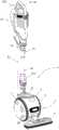
图1是根据本发明的吸尘器在第一使用配置中的立体图;Figure 1 is a perspective view of a vacuum cleaner according to the invention in a first use configuration;
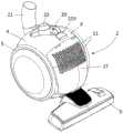
图2是图1的吸尘器在第二使用配置中的立体图;Fig. 2 is a perspective view of the vacuum cleaner of Fig. 1 in a second use configuration;
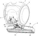
图3是图1的吸尘器的局部立体图;Fig. 3 is a partial perspective view of the vacuum cleaner in Fig. 1;
图4是图1的吸尘器的局部俯视立体图;Fig. 4 is a partial top perspective view of the vacuum cleaner in Fig. 1;
图5是图1的吸尘器的局部仰视立体图;Fig. 5 is a partial bottom perspective view of the vacuum cleaner in Fig. 1;
图6是图1的吸尘器的局部仰视立体图;Fig. 6 is a partial bottom perspective view of the vacuum cleaner in Fig. 1;
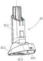
图7是图1的吸尘器的吸嘴的仰视立体图;Fig. 7 is a bottom perspective view of the suction nozzle of the vacuum cleaner in Fig. 1;
图8是图1的吸尘器在第一操作位置中的局部纵向剖视图;Fig. 8 is a partial longitudinal sectional view of the vacuum cleaner of Fig. 1 in the first operating position;
图9是图1的吸尘器在第二操作位置中的局部纵向剖视图;Fig. 9 is a partial longitudinal sectional view of the vacuum cleaner of Fig. 1 in a second operating position;
图10是图1的吸尘器在第三操作位置中的局部纵向剖视图;Fig. 10 is a partial longitudinal sectional view of the vacuum cleaner of Fig. 1 in a third operating position;
图11是图1的吸尘器在第四操作位置中的局部纵向剖视图。Fig. 11 is a partial longitudinal sectional view of the vacuum cleaner of Fig. 1 in a fourth operating position.
具体实施方式Detailed ways
仅示出了理解本发明所必需的元件。为了便于阅读附图,不同图中用相同的附图标记表示相同的元件。Only elements necessary for understanding the invention are shown. In order to facilitate reading of the drawings, the same reference numerals are used to designate the same elements in different figures.
应当注意,在本文件中,用于描述吸尘器或主体的术语“水平”、“竖直”、“下”、“上”、“前”、和“后”是参照吸尘器通过其轮子搁放在平坦且水平的待清洁地板上的使用情形。在本文件中,术语“向前倾斜”意味着朝向主吸头倾斜,从而远离通常在主吸头前方操作吸尘器的使用者,而术语“向后倾斜”意味着远离主吸头倾斜,从而朝向通常在主吸头前方操作吸尘器的使用者。It should be noted that in this document, the terms "horizontal", "vertical", "lower", "upper", "front", and "rear" used to describe the vacuum cleaner or the main body refer to Use on a flat and level floor to be cleaned. In this document, the term "tilted forward" means tilted towards the main nozzle, away from the user who would normally operate the vacuum cleaner in front of the main nozzle, and the term "tilted backward" means tilted away from the main nozzle, so A user who normally operates the vacuum cleaner in front of the main suction head.
图1至图11示出了扫把式吸尘器1。1 to 11 show a
吸尘器1包括主体2,主体2配置成搁放在待清洁的地板上并且在待清洁的地板上滚动。主体2特别地包括设有例如部分球形的壳体外表面4的吸尘器壳体3,以及安装成能相对于吸尘器壳体3旋转移动的第一和第二主轮5、6。The
第一和第二主轮5、6分别包括第一和第二条带7、8,以便主体2可搁放在待清洁的地板上和在待清洁的地板上滚动。第一和第二主轮5、6设置在吸尘器壳体3的两侧。更具体地,第一和第二主轮5、6是吸尘器1的侧轮。The first and second
如图6更具体地所示,第一和第二主轮5、6的旋转轴相对于彼此倾斜,优选向主体2的顶部会聚,在顶点形成小于180°的角度。然而,根据本发明的替代实施例,第一和第二主轮5、6的旋转轴可以是共线的。As shown more particularly in FIG. 6 , the axes of rotation of the first and second
根据图中所示的实施例,主体2具有总体上球形的形状。主体2的这种配置有利于避开出现在主体2前方的障碍物。有利的是,壳体外表面4以及第一和第二主轮5、6部分地形成总体上球形的整体。根据本发明的替代实施例,第一和第二主轮5、6是环形的,并且安装成能分别绕第一和第二固定轮毂旋转移动,并且壳体外表面4和第一和第二固定轮毂部分地形成总体上球形的整体。According to the embodiment shown in the figures, the
吸尘器1还包括主吸头9和多个排气口11,吸尘器1可通过主吸头9抽吸外部空气,经由吸尘器1清洁的空气可通过排气口11离开吸尘器1。The
吸尘器1还包括在主吸头9和排气口11之间延伸的空气回路12,以及容纳在吸尘器壳体3中并设置在空气回路12上方的抽吸电机13。抽吸电机13包括电动机和联接到电动机的风扇,用于在从主吸头9到排气口11的空气回路12中产生气流。The
吸尘器1还包括废物分离和收集装置14,废物分离和收集装置14设置在抽吸电机13上游的空气回路12上方,并且配置成被抽吸电机13产生的气流穿过。根据图中所示的实施例,废物分离和收集装置14是旋风型的,并且包括废物收集容器和旋风分离室,所述旋风分离室是环形的并且由废物收集容器的侧壁在外部界定。The
吸尘器1还包括机械地连接到吸尘器壳体3的握柄15。根据图中所示的实施例,握柄15部分地界定空气回路12,并且废物分离和收集装置14例如可拆卸地安装在握柄15上。The
如图1和图2所示,握柄15包括:As shown in Figures 1 and 2, the
-抽吸管16,其配置成机械地连接到吸尘器壳体3并且流体地连结到主吸头9,以及- a
-抓握部分17,其包括握柄18和联接部分19,联接部分19是管状的并且流体地连结到抽吸管16。-
根据图1所示的实施例,联接部分19可拆卸地连接到抽吸管16上。然而,根据本发明的替代实施例,联接部分19可以安装成在第一手柄配置和第二手柄配置之间铰接在抽吸管16上,在第一手柄配置中,联接部分19基本平行于抽吸管16延伸,在第二手柄配置中,联接部分19相对于抽吸管16倾斜。According to the embodiment shown in FIG. 1 , the
吸尘器1还包括抽吸导管21,抽吸导管21是柔性的,并且部分地界定空气回路12。抽吸导管21包括机械地连接到吸尘器壳体3并流体地连结到抽吸电机13的第一端部,以及机械地连接并流体地连结到握柄15的近端部15.1(例如连接到把手18)的第二端部。The
有利的是,握柄15具有远端部15.2,所述远端部15.2由抽吸管16限定并且配有副吸头22,所述副吸头22可拆卸地紧固到吸尘器壳体3,并且当副吸头22紧固到吸尘器壳体3时以及当副吸头22从吸尘器壳体3上分离时,所述副吸头22都流体地连结到抽吸电机13。有利的是,副吸头22的横向尺寸小于主吸头9的横向尺寸。Advantageously, the
副吸头22配置成当副吸头22紧固到吸尘器壳体3时,优选密封地流体地连结到主吸头9,从而确保主吸头9抽吸的气流流向废物分离和收集装置14。副吸头22还配置成当副吸头22从吸尘器壳体3分离时,确保对用主吸头9无法进入的待清洁区域(例如天花板或低矮家具)进行吸尘。The
如图7更具体地所示,副吸头22包括:As shown more specifically in Figure 7, the
-管状的并且套配有抽吸管16的紧固部分22.1,- a fastening part 22.1 tubular and fitted with the
-可拆卸地紧固到吸尘器壳体3上的清洁部分22.2,以及- a cleaning part 22.2 detachably fastened to the
-中间部分22.3,其设置在紧固部分22.1和清洁部分22.2之间,并且将清洁部分22.2机械地连接到紧固部分22.1。- An intermediate part 22.3, which is arranged between the fastening part 22.1 and the cleaning part 22.2 and mechanically connects the cleaning part 22.2 to the fastening part 22.1.
有利的是,当副吸头22紧固到吸尘器壳体3上时,清洁部分22.2的外表面与壳体外表面4基本齐平。Advantageously, when the
根据图中所示的实施例,吸尘器壳体3包括容纳凹部20,所述容纳凹部在壳体外表面4中开口,并且配置成当副吸头22紧固到吸尘器壳体3上时,至少部分地容纳清洁部分22.2。有利的是,容纳凹部20设置在吸尘器壳体3的上部。According to the embodiment shown in the figures, the vacuum
如图4更具体地所示,主体2具有连接套筒23,连接套筒23设置在吸尘器壳体3上,当副吸头22紧固在吸尘器壳体3上时,副吸头22连接到连接套筒23上。连接套筒23设置在吸尘器壳体3的上部,并且例如设置在吸尘器壳体3的后上部。As shown more specifically in Fig. 4, the
连接套筒23从壳体外表面4突出,尤其是从容纳凹部20的底壁延伸。有利的是,吸尘器1包括柔性联接导管24,其位于吸尘器壳体3中,并且将主吸头9流体地连接到连接套筒23。The
根据图中所示的实施例,清洁部分22.2安装成绕枢轴B(见图8)相对于紧固部分22.1枢转、进而相对于抽吸管16枢转,枢轴B垂直于抽吸管16的中心纵轴延伸,并且当副吸头22紧固在吸尘器壳体3上且第一和第二主轮5、6搁放在水平表面上时,枢轴B基本水平延伸。According to the embodiment shown in the figures, the cleaning part 22.2 is mounted to pivot relative to the fastening part 22.1 and thus relative to the
有利的是,清洁部分22.2安装成绕枢轴B相对于中间部分22.3枢转,紧固部分22.1安装成绕基本垂直于枢轴B的附加枢轴C相对于中间部分22.3枢转。Advantageously, the cleaning part 22.2 is mounted to pivot about a pivot B relative to the middle part 22.3 and the fastening part 22.1 is mounted to pivot about an additional pivot C substantially perpendicular to the pivot B relative to the middle part 22.3.
根据图中所示的实施例,吸尘器1包括锁紧装置220,所述锁紧装置220配置成当副吸头22紧固到吸尘器壳体3上时防止清洁部分22.2绕枢轴B枢转。锁紧装置220例如可以至少部分地由连接套筒23形成。According to the embodiment shown in the figures, the
如图8所示,紧固部分22.1包括内导管224,所述内导管配置成当副吸头22紧固到吸尘器壳体3上时流体地连结到连接套筒23。更具体地,内导管224包括管状的远端部,当副吸头22紧固到吸尘器壳体3上时,所述远端部上套配有连接套筒23。有利的是,附加枢轴C基本上与内导管224的远端部的中心纵轴共线。As shown in FIG. 8 , the fastening part 22.1 comprises an
根据图中所示的实施例,吸尘器1包括锁定构件221,如锁定指状件,其安装成能在锁定位置和释放位置之间在吸尘器壳体3的上部移动,在锁定位置,锁定构件221将副吸头22锁定在吸尘器壳体3上,并且防止副吸头22从吸尘器壳体3分离,在释放位置,锁定构件221释放副吸头22,并且准许副吸头22从吸尘器壳体3分离。有利的是,副吸头22包括锁定元件222,例如锁定凹部,其设置在清洁部分22.2上,并且配置成当锁定构件221处在锁定位置时与锁定构件221配合。According to the embodiment shown in the figures, the
吸尘器1还包括设置在吸尘器壳体3上的解锁构件223,如解锁按钮,其配置成将锁定构件221向释放位置移动,还包括偏置构件(图中不可见),其配置成将锁定构件221向锁定位置偏置。The
吸尘器1还包括可充电电池25,其配置成为抽吸电机13供电。可充电电池25设置在至少部分由吸尘器壳体3界定的电池仓中。有利的是,可充电电池25是可拆卸的,并且配置成经由设置在吸尘器壳体3上并且在电池仓中开口的进入开口26从电池仓中取出和放入电池仓中。The
根据图中所示的实施例,吸尘器1包括进入挡板27,所述进入挡板27安装成在关闭位置和打开位置绕进入挡板的枢轴之间相对于吸尘器壳体3枢转,在关闭位置,进入挡板27至少部分关闭进入开口26,并且防止可充电电池25从电池仓中取出,在打开位置,进入挡板27释放进入开口26,并且准许可充电电池25从电池仓中取出。如图4和图6所示,排气口11设置在进入挡板27上。According to the embodiment shown in the figures, the
如图8至图11所示,主吸头9安装成在主吸头9靠近吸尘器壳体3前边缘的缩回位置(见图9)和主吸头9远离吸尘器壳体3前边缘的展开位置(见图11)之间绕横向铰接轴A铰接在吸尘器壳体3上。更具体地,当主吸头9处在缩回位置时,主吸头9延伸超过吸尘器壳体3的前边缘第一展开距离,并且当主吸头9处在展开位置时,主吸头9延伸超过吸尘器壳体3的前边缘第二展开距离,第二展开距离大于第一展开距离。As shown in FIGS. 8 to 11 , the
根据图中所示的实施例,横向铰接轴A在吸尘器1的第一和第二主轮5、6搁放在水平表面上时基本上是水平的,并且垂直于主体2的移动方向D延伸。有利的是,横向铰接轴A位于吸尘器壳体3的后下部。如图9中更具体示出的,当吸尘器处在预定操作位置时,横向铰接轴A位于第一和第二主轮5、6的旋转轴的后方。According to the embodiment shown in the figures, the transverse articulation axis A is substantially horizontal when the first and second
根据图中所示的实施例,主吸头9包括:According to the embodiment shown in the figures, the
-底板28,其设有下表面29和在下表面29上开口的抽吸腔31,以及- a
-安装成通过限定前枢轴的前枢转联接件铰接在底板28上的叉32,叉32包括安装成通过限定横向铰接轴A的后枢转联接件铰接在吸尘器壳体3上的两个叉臂33。- a
有利的是,抽吸腔31是细长的,并且沿横向于主体2的移动方向的延伸方向延伸。Advantageously, the
如图8至图11更具体地所示,吸尘器1配置成:As shown more specifically in FIGS. 8 to 11 , the
-使得握柄15和吸尘器壳体3从吸尘器1的预定操作位置(有利地对应于吸尘器1的存放位置,也称为停放位置)的向后倾斜引起横向铰接轴A的向前移动,例如沿着大致弧形的轨迹,并因此引起主吸头9向展开位置的移动,并且- so that the rearward tilting of the
-使得握柄15和吸尘器壳体3朝向吸尘器1的预定操作位置的向前倾斜引起横向铰接轴A的向后移动,例如沿着大致弧形的路径,并因此引起主吸头9向缩回位置的移动。- such that forward tilting of the
有利的是,吸尘器1包括锁定装置34,所述锁定装置34配置成处在:Advantageously, the
-锁定配置,在锁定配置中锁定装置34将主吸头9锁定在缩回位置,并防止主吸头9绕横向铰接轴A枢转,从而防止主吸头9向展开位置移动,以及- a locked configuration, in which the locking means 34 lock the
-释放配置,在释放配置中锁定装置34释放主吸头9,并允许主吸头9绕横向铰接轴A枢转,从而准许主吸头9向展开位置移动。- A release configuration, in which the locking means 34 release the
锁定装置34特别允许在吸尘器1处在存放位置时能够运输吸尘器1,不会出现主吸头9向下倾斜的风险。The locking
根据图中所示的实施例,锁定装置34包括设置在吸尘器壳体3上的第一锁定元件35和设置在主吸头9上部并且位于横向铰接轴A的前方的第二锁定元件36。第二锁定元件36配置成当主吸头9处在缩回位置时例如通过磁化或卡扣与第一锁定元件35配合,从而将主吸头9锁定在缩回位置。According to the embodiment shown in the figure, the locking
为了能够解锁主吸头9,从而允许主吸头9向展开位置移动,吸尘器1有利地包括致动构件,致动构件配置成当吸尘器壳体3和握柄15从预定操作位置向后倾斜时,将锁定装置34自动移动到释放配置。In order to be able to unlock the
根据本发明的实施例,致动构件包括两个支承部分38,如支承靴,分别设置在叉臂33上,并且位于横向铰接轴A的后方。According to an embodiment of the invention, the actuating member comprises two bearing
支承部分38更具体地配置成当吸尘器壳体3和握柄15从预定操作位置向后倾斜时支承在地板上,并在第二锁定元件36上施加释放力,使得施加在第二锁定元件36上的力的合力大于第一锁定元件35施加在第二锁定元件36上的锁定力,并与之相反。换句话说,当吸尘器壳体3和握柄15从预定操作位置向后倾斜时,支承部分38配置成抵抗第一锁定元件35施加在第二锁定元件36上的力,使主吸头9离吸尘器壳体3一段距离绕横向铰接轴A枢转。吸尘器1的这种配置确保了当握柄15向后倾斜时锁定装置34自动移动到释放配置,并因此允许主吸头9在缩回位置和展开位置之间移动。The supporting
吸尘器1更具体地配置成使得握柄15和吸尘器壳体3从预定操作位置的向后倾斜引起主吸头9根据移动行程从缩回位置移动到展开位置,所述移动行程包括:The
-第一行程部分,在第一行程部分期间,主吸头9被锁定装置34锁定在缩回位置,并被吸尘器壳体3根据包括至少一个竖直分量的移动运动而移动,从而引起主吸头9的升高,- a first stroke portion, during which the
-第二行程部分,在第二行程部分期间,致动构件将锁定装置34移动到释放配置,以便释放主吸头9,并允许主吸头9通过重力移动,直到主吸头9与待清洁的表面接触,以及- a second stroke portion, during which the actuating member moves the
-第三行程部分,在第三行程部分期间,主吸头9沿着基本水平且垂直于横向铰接轴A的平移方向离吸尘器壳体3一段距离相对于吸尘器壳体3平移移动。- A third stroke portion, during which the
根据图中未示出的本发明的实施例,废物分离和收集装置14可以例如可拆卸地安装在吸尘器壳体3上,并且尤其位于握柄15的前方。According to an embodiment of the invention not shown in the figures, the waste separation and
当然,本发明决不限于前面描述和说明的实施例,这些实施例仅作为例子给出。尤其在各种元件的构成方面或者通过等效技术的取代,可以有一些修改,这并不脱离本发明的保护范围。Of course, the invention is by no means limited to the embodiments described and illustrated above, which are given by way of example only. Modifications are possible, especially in the composition of the various elements or by substitution of equivalent techniques, without departing from the scope of protection of the present invention.
Claims (17)
Applications Claiming Priority (2)
| Application Number | Priority Date | Filing Date | Title |
|---|---|---|---|
| FR2112547AFR3129281B1 (en) | 2021-11-25 | 2021-11-25 | Vacuum cleaner equipped with a secondary suction head |
| FRFR2112547 | 2021-11-25 |
Publications (1)
| Publication Number | Publication Date |
|---|---|
| CN116158687Atrue CN116158687A (en) | 2023-05-26 |
Family
ID=79831614
Family Applications (1)
| Application Number | Title | Priority Date | Filing Date |
|---|---|---|---|
| CN202211491766.5APendingCN116158687A (en) | 2021-11-25 | 2022-11-25 | Vacuum cleaner with auxiliary head |
Country Status (3)
| Country | Link |
|---|---|
| EP (1) | EP4186401A3 (en) |
| CN (1) | CN116158687A (en) |
| FR (1) | FR3129281B1 (en) |
Family Cites Families (3)
| Publication number | Priority date | Publication date | Assignee | Title |
|---|---|---|---|---|
| GB2307848A (en)* | 1995-12-04 | 1997-06-11 | Electrolux Ltd | A suction cleaner with an auxiliary cleaner |
| CN101626715B (en)* | 2006-12-12 | 2012-07-25 | Gbd公司 | Convertible surface cleaning apparatus |
| US20160157690A1 (en)* | 2014-12-05 | 2016-06-09 | Panasonic Corporation Of North America | Upright vacuum cleaner with swivel connection between nozzle and handle assemblies |
- 2021
- 2021-11-25FRFR2112547Apatent/FR3129281B1/enactiveActive
- 2022
- 2022-11-22EPEP22208896.5Apatent/EP4186401A3/enactivePending
- 2022-11-25CNCN202211491766.5Apatent/CN116158687A/enactivePending
Also Published As
| Publication number | Publication date |
|---|---|
| FR3129281A1 (en) | 2023-05-26 |
| EP4186401A2 (en) | 2023-05-31 |
| EP4186401A3 (en) | 2023-06-07 |
| FR3129281B1 (en) | 2023-12-29 |
Similar Documents
| Publication | Publication Date | Title |
|---|---|---|
| US20240180375A1 (en) | Vacuum cleaning device with foldable wand to provide storage configuration | |
| US20230200604A1 (en) | Vacuum cleaner | |
| CN100593387C (en) | vacuum cleaner | |
| CN113613534B (en) | Portable Extractor | |
| JP6700181B2 (en) | Surface cleaning device configurable in storage position | |
| US11771280B2 (en) | Surface cleaning apparatus with removable air treatment member assembly | |
| US11445878B2 (en) | Surface cleaning apparatus with removable air treatment member assembly | |
| US20090064449A1 (en) | Surface treating appliance | |
| CN104644060B (en) | For the pivoting handle of surface cleaning apparatus | |
| US20210386259A1 (en) | Surface cleaning apparatus | |
| CN109310254B (en) | Surface cleaning device | |
| CN102462441B (en) | upright vacuum cleaner | |
| CN116158687A (en) | Vacuum cleaner with auxiliary head | |
| JP4258730B2 (en) | Electric vacuum cleaner | |
| CN116158686A (en) | Vacuum cleaners with suction heads movable between retracted and extended positions | |
| CN221285597U (en) | Tank-type dust collector accessory and tank-type dust collector comprising same | |
| US11766156B2 (en) | Surface cleaning apparatus with removable air treatment member assembly | |
| US10178930B2 (en) | Maneuverable cordless stick vacuum | |
| CN222968466U (en) | Sled suction assembly | |
| JP7174654B2 (en) | vacuum cleaner | |
| US20210290015A1 (en) | Surface cleaning apparatus with removable air treatment member assembly | |
| CN116847769A (en) | Inhalation assembly comprising a waste separating and collecting device equipped with a locking member | |
| JP2000217750A (en) | Suction port body and vacuum cleaner |
Legal Events
| Date | Code | Title | Description |
|---|---|---|---|
| PB01 | Publication | ||
| PB01 | Publication | ||
| SE01 | Entry into force of request for substantive examination | ||
| SE01 | Entry into force of request for substantive examination |