CN116149193B - Anti-disturbance control method and system for rotor unmanned aerial vehicle based on vision - Google Patents
Anti-disturbance control method and system for rotor unmanned aerial vehicle based on visionDownload PDFInfo
- Publication number
- CN116149193B CN116149193BCN202310443703.0ACN202310443703ACN116149193BCN 116149193 BCN116149193 BCN 116149193BCN 202310443703 ACN202310443703 ACN 202310443703ACN 116149193 BCN116149193 BCN 116149193B
- Authority
- CN
- China
- Prior art keywords
- disturbance
- control
- error vector
- attitude
- rotary
- Prior art date
- Legal status (The legal status is an assumption and is not a legal conclusion. Google has not performed a legal analysis and makes no representation as to the accuracy of the status listed.)
- Active
Links
- 238000000034methodMethods0.000titleclaimsabstractdescription64
- 239000013598vectorSubstances0.000claimsabstractdescription117
- 230000000007visual effectEffects0.000claimsabstractdescription59
- 239000011159matrix materialSubstances0.000claimsdescription90
- 230000003044adaptive effectEffects0.000claimsdescription12
- 238000012545processingMethods0.000claimsdescription12
- 238000005259measurementMethods0.000claimsdescription6
- 239000012528membraneSubstances0.000claimsdescription6
- 238000013178mathematical modelMethods0.000claimsdescription4
- 239000013641positive controlSubstances0.000claimsdescription4
- 238000010586diagramMethods0.000description8
- 230000005484gravityEffects0.000description5
- 101000827703Homo sapiens Polyphosphoinositide phosphataseProteins0.000description2
- 102100023591Polyphosphoinositide phosphataseHuman genes0.000description2
- 230000001133accelerationEffects0.000description2
- 238000012986modificationMethods0.000description2
- 230000004048modificationEffects0.000description2
- 230000003287optical effectEffects0.000description2
- 238000012360testing methodMethods0.000description2
- 101001121408Homo sapiens L-amino-acid oxidaseProteins0.000description1
- 102100026388L-amino-acid oxidaseHuman genes0.000description1
- 206010034719Personality changeDiseases0.000description1
- 101100012902Saccharomyces cerevisiae (strain ATCC 204508 / S288c) FIG2 geneProteins0.000description1
- 238000004364calculation methodMethods0.000description1
- 244000145845chatteringSpecies0.000description1
- 238000011161developmentMethods0.000description1
- 238000002474experimental methodMethods0.000description1
- 238000011160researchMethods0.000description1
- 230000006641stabilisationEffects0.000description1
- 238000011105stabilizationMethods0.000description1
Images


Classifications
- G—PHYSICS
- G05—CONTROLLING; REGULATING
- G05B—CONTROL OR REGULATING SYSTEMS IN GENERAL; FUNCTIONAL ELEMENTS OF SUCH SYSTEMS; MONITORING OR TESTING ARRANGEMENTS FOR SUCH SYSTEMS OR ELEMENTS
- G05B13/00—Adaptive control systems, i.e. systems automatically adjusting themselves to have a performance which is optimum according to some preassigned criterion
- G05B13/02—Adaptive control systems, i.e. systems automatically adjusting themselves to have a performance which is optimum according to some preassigned criterion electric
- G05B13/04—Adaptive control systems, i.e. systems automatically adjusting themselves to have a performance which is optimum according to some preassigned criterion electric involving the use of models or simulators
- G05B13/042—Adaptive control systems, i.e. systems automatically adjusting themselves to have a performance which is optimum according to some preassigned criterion electric involving the use of models or simulators in which a parameter or coefficient is automatically adjusted to optimise the performance
- G—PHYSICS
- G05—CONTROLLING; REGULATING
- G05D—SYSTEMS FOR CONTROLLING OR REGULATING NON-ELECTRIC VARIABLES
- G05D1/00—Control of position, course, altitude or attitude of land, water, air or space vehicles, e.g. using automatic pilots
- G05D1/10—Simultaneous control of position or course in three dimensions
- G05D1/101—Simultaneous control of position or course in three dimensions specially adapted for aircraft
Landscapes
- Engineering & Computer Science (AREA)
- Physics & Mathematics (AREA)
- Automation & Control Theory (AREA)
- General Physics & Mathematics (AREA)
- Computer Vision & Pattern Recognition (AREA)
- Medical Informatics (AREA)
- Software Systems (AREA)
- Evolutionary Computation (AREA)
- Health & Medical Sciences (AREA)
- Artificial Intelligence (AREA)
- Aviation & Aerospace Engineering (AREA)
- Radar, Positioning & Navigation (AREA)
- Remote Sensing (AREA)
- Control Of Position, Course, Altitude, Or Attitude Of Moving Bodies (AREA)
Abstract
Translated fromChinese
Description
Translated fromChinese技术领域Technical Field
本发明涉及旋翼无人机自主控制领域,特别涉及一种存在外界扰动下基于视觉的旋翼无人机扰动控制方法及系统。The present invention relates to the field of autonomous control of rotary-wing unmanned aerial vehicles, and in particular to a vision-based disturbance control method and system for rotary-wing unmanned aerial vehicles in the presence of external disturbances.
背景技术Background Art
旋翼无人机是一种通过旋转叶片产生升力的飞行器,广泛应用于空中摄影、农业、科学研究和军事任务等领域。与固定翼无人机不同,旋翼无人机具有垂直起降和在狭小空间内悬停和飞行等优势。随着技术的不断进步,旋翼无人机在一些人类难以到达的环境和具有挑战的项目中表现出越来越强大的能力,逐渐取代载人飞行器。但是,旋翼无人机在应用过程中也面临着一些挑战,如外界扰动的影响以及高效的自我姿态控制问题。因此,采用基于机载视觉传感器的自抗扰技术和姿态控制技术成为旋翼无人机在复杂环境中实现自主飞行的关键。Rotary-wing UAVs are aircraft that generate lift through rotating blades and are widely used in aerial photography, agriculture, scientific research, and military missions. Unlike fixed-wing UAVs, rotary-wing UAVs have advantages such as vertical take-off and landing, hovering and flying in a small space. With the continuous advancement of technology, rotary-wing UAVs have shown increasingly powerful capabilities in some environments that are difficult for humans to reach and challenging projects, gradually replacing manned aircraft. However, rotary-wing UAVs also face some challenges in the application process, such as the influence of external disturbances and the problem of efficient self-attitude control. Therefore, the use of self-anti-disturbance technology and attitude control technology based on airborne visual sensors has become the key to the realization of autonomous flight of rotary-wing UAVs in complex environments.
旋翼无人机在飞行过程中可能会受到各种扰动,这些扰动可能来自外界环境或无人机本身的动力系统,包括风扰动、气流扰动、操纵系统扰动以及负载扰动等,这些扰动都会影响旋翼无人机的稳定性。在旋翼无人机自主飞行过程中,受到的外界扰动是一个不可测量的量。对于旋翼无人机来说,如何获取外部扰动量仍然是一个悬而未决的问题。同时,旋翼无人机是一个欠驱动的系统,位置和姿态变化是高度耦合的。只有在姿态快速稳定的前提下,旋翼无人机的整个系统才会快速稳定。Rotary-wing UAVs may be subject to various disturbances during flight. These disturbances may come from the external environment or the power system of the UAV itself, including wind disturbances, airflow disturbances, control system disturbances, and load disturbances, etc. These disturbances will affect the stability of the rotary-wing UAV. During the autonomous flight of the rotary-wing UAV, the external disturbance is an unmeasurable quantity. For rotary-wing UAVs, how to obtain the external disturbance amount is still an unresolved issue. At the same time, the rotary-wing UAV is an under-driven system, and the position and attitude changes are highly coupled. Only when the attitude is quickly and steadily, the entire system of the rotary-wing UAV will be quickly and steadily.
在受到扰动的环境中,旋翼无人机需要具备高动态鲁棒性的姿态控制能力。然而,传统的控制器已经无法满足这种需求。因此,需要采用新的控制方法,以使旋翼无人机在更为复杂的环境下仍能保持高鲁棒性的控制能力。In a disturbed environment, rotorcraft UAVs need to have highly dynamic and robust attitude control capabilities. However, traditional controllers can no longer meet this requirement. Therefore, new control methods are needed to enable rotorcraft UAVs to maintain highly robust control capabilities in more complex environments.
发明内容Summary of the invention
本发明的目的在于针对当前旋翼无人机系统的在扰动环境下控制鲁棒性不足,提出了一种基于视觉的旋翼无人机抗扰动控制方法及系统,该方法中旋翼无人机无需知道自身的位置信息,仅通过视觉信息就可以实现悬停、降落、目标跟踪以及抗外界扰动等多项任务。采用一个视野向下摄像头的图像输入,通过求解一幅参考图像和当前图像的单应性矩阵作为视觉特征,提出了一种新的自适应滑膜几何姿态控制器用以控制旋翼无人机的姿态,同时设计了一个自身的扰动观测器来观测各种扰动,提高控制器的鲁棒性,实现了在扰动环境下的鲁棒控制,解决了传统旋翼无人机在扰动环境中实现悬停、降落、跟踪等多种任务中鲁棒性不足的问题。The purpose of the present invention is to address the lack of control robustness of current rotor UAV systems in a disturbed environment, and propose a vision-based anti-disturbance control method and system for rotor UAVs. In this method, the rotor UAV does not need to know its own position information, and can achieve multiple tasks such as hovering, landing, target tracking, and anti-external disturbance through visual information alone. Using the image input of a downward-looking camera, by solving the homography matrix of a reference image and the current image as the visual feature, a new adaptive sliding film geometry attitude controller is proposed to control the attitude of the rotor UAV. At the same time, a disturbance observer is designed to observe various disturbances, improve the robustness of the controller, and achieve robust control in a disturbed environment, solving the problem of insufficient robustness of traditional rotor UAVs in achieving multiple tasks such as hovering, landing, and tracking in a disturbed environment.
本发明的目的在于提供一种基于视觉的旋翼无人机抗扰动控制方法,包括如下步骤:The object of the present invention is to provide a vision-based anti-disturbance control method for a rotary-wing UAV, comprising the following steps:
S1、通过相机实时采集周围环境图像,通过飞行控制器中的惯性里程计实时采集旋翼无人机的角速度,机载处理器接收周围环境图像并处理得到单应性矩阵,根据单应性矩阵和预设的虚拟控制误差函数得到第一控制误差向量;S1, collecting the surrounding environment image in real time through the camera, collecting the angular velocity of the rotor UAV in real time through the inertial odometer in the flight controller, the onboard processor receives the surrounding environment image and processes it to obtain the homography matrix, and obtains the first control error vector according to the homography matrix and the preset virtual control error function;
S2、根据单应性矩阵设置扰动观测器,扰动观测器根据第一控制误差向量和角速度估计旋翼无人机的外部扰动量,外部扰动量包括外部扰动力和外部扰动力矩;S2. Setting a disturbance observer according to the homography matrix, wherein the disturbance observer estimates an external disturbance of the rotor UAV according to the first control error vector and the angular velocity, wherein the external disturbance includes an external disturbance force and an external disturbance torque;
S3、设置虚拟控制输入力,根据第一控制误差向量和虚拟控制输入力设置视觉外环控制器,将外部扰动力输入至视觉外环控制器,经过处理,得到期望推力,将期望推力通过机载处理器输出;S3, setting a virtual control input force, setting a visual outer loop controller according to the first control error vector and the virtual control input force, inputting an external disturbance force into the visual outer loop controller, obtaining a desired thrust after processing, and outputting the desired thrust through an onboard processor;
S4、根据虚拟控制输入力设置姿态内环控制器,将外部扰动力矩输入至姿态内环控制器,经过处理,得到期望控制力矩,将期望控制力矩通过机载处理器输出;S4, setting an attitude inner loop controller according to the virtual control input force, inputting the external disturbance torque into the attitude inner loop controller, obtaining the desired control torque after processing, and outputting the desired control torque through the onboard processor;
S5、飞行控制器接收机载处理器输出的期望推力和期望控制力矩,并根据期望推力和期望控制力矩控制旋翼无人机的鲁棒飞行。S5. The flight controller receives the desired thrust and the desired control torque output by the onboard processor, and controls the robust flight of the rotor UAV according to the desired thrust and the desired control torque.
优选地,S1中根据单应性矩阵和预设的虚拟控制误差函数得到第一控制误差向量,第一控制误差向量具体为:Preferably, in S1, a first control error vector is obtained according to the homography matrix and a preset virtual control error function. The first control error vector is specifically:

其中,
式中,


优选地,S2中根据单应性矩阵设置扰动观测器,具体包括:Preferably, in S2, a disturbance observer is set according to the homography matrix, specifically including:
S21、根据单应性矩阵和旋翼无人机的数学模型设置旋翼无人机的视觉伺服模型;S21, setting a visual servo model of the rotary-wing UAV according to the homography matrix and the mathematical model of the rotary-wing UAV;
S22、重写旋翼无人机的视觉伺服模型,得到包含扰动的动力学模型;S22, rewrite the visual servo model of the rotary wing UAV to obtain a dynamic model including disturbances;
S23、设置包含扰动的动力学模型趋于稳定时对应的扰动观测器。S23. Setting a disturbance observer corresponding to when the dynamic model containing disturbance tends to be stable.
优选地,S23设置包含扰动的动力学模型趋于稳定时对应的扰动观测器,扰动观测器具体为:Preferably, S23 sets a disturbance observer corresponding to when the dynamic model containing the disturbance tends to be stable, and the disturbance observer is specifically:


其中,
式中,


优选地,S3中根据第一控制误差向量和虚拟控制输入力设置视觉外环控制器,具体包括:Preferably, setting a visual outer loop controller according to the first control error vector and the virtual control input force in S3 specifically includes:
S31、根据第一控制误差向量构建第二控制误差向量;S31, constructing a second control error vector according to the first control error vector;
S32、分别对第一控制误差向量和第二控制误差向量求一阶导数,并结合虚拟控制力得到视觉外环动态方程;S32, respectively calculating the first-order derivatives of the first control error vector and the second control error vector, and combining the virtual control force to obtain the visual outer loop dynamic equation;
S33、设置视觉外环动态方程趋于稳定时对应的视觉外环控制器。S33, setting a corresponding visual outer loop controller when the visual outer loop dynamic equation tends to be stable.
优选地,S33设置视觉外环动态方程趋于稳定时对应的视觉外环控制器,视觉外环控制器具体为:Preferably, S33 sets a corresponding visual outer loop controller when the visual outer loop dynamic equation tends to be stable, and the visual outer loop controller is specifically:

其中,
其中,


优选地,S4中根据虚拟控制输入力设置姿态内环控制器,具体包括:Preferably, setting the attitude inner loop controller according to the virtual control input force in S4 specifically includes:
S41、根据虚拟控制输入力构建期望姿态矩阵;S41, constructing a desired posture matrix according to the virtual control input force;
S42、根据期望姿态矩阵在李群空间定义姿态误差向量和姿态角速度误差向量;S42, defining a posture error vector and a posture angular velocity error vector in a Lie group space according to the expected posture matrix;
S43、分别对姿态误差向量和姿态角速度误差向量求一阶导数,得到姿态内环动态方程;S43, respectively calculating the first-order derivatives of the attitude error vector and the attitude angular velocity error vector to obtain the attitude inner loop dynamic equation;
S44、根据姿态误差向量和姿态角速度误差向量设置滑膜面,结合姿态内环动态方程设置滑膜面趋于稳定时对应的姿态内环控制器。S44, setting a sliding film surface according to the attitude error vector and the attitude angular velocity error vector, and setting a corresponding attitude inner loop controller when the sliding film surface tends to be stable in combination with the attitude inner loop dynamic equation.
优选地,S44根据姿态误差向量和姿态角速度误差向量设置滑膜面,滑膜面具体为:Preferably, S44 sets a sliding film surface according to the attitude error vector and the attitude angular velocity error vector, and the sliding film surface is specifically:

其中,

式中,


优选地,S44结合姿态内环动态方程设置滑膜面趋于稳定时对应的姿态内环控制器,姿态内环控制器具体为:Preferably, S44 sets a corresponding attitude inner loop controller when the sliding membrane surface tends to be stable in combination with the attitude inner loop dynamic equation, and the attitude inner loop controller is specifically:

其中,


式中,


一种基于视觉的旋翼无人机抗扰动控制系统,使用基于视觉的旋翼无人机抗扰动控制方法对旋翼无人机进行控制,系统包括:旋翼无人机、相机、机载处理器和飞行控制器,A vision-based anti-disturbance control system for a rotary-wing UAV uses a vision-based anti-disturbance control method for a rotary-wing UAV to control the rotary-wing UAV. The system includes: a rotary-wing UAV, a camera, an airborne processor, and a flight controller.
相机设置于旋翼无人机的正下方,用于实时采集周围环境图像;The camera is set directly below the rotor drone to collect images of the surrounding environment in real time;
飞行控制器设置于旋翼无人机上,飞行控制器包括惯性测量单元,惯性测量单元用于实时测量旋翼无人机的角速度;The flight controller is arranged on the rotor UAV, and the flight controller includes an inertial measurement unit, and the inertial measurement unit is used to measure the angular velocity of the rotor UAV in real time;
机载处理器设置于旋翼无人机上,机载处理器中设置了视觉外环控制器和姿态内环控制器,机载处理器通过视觉外环控制器和姿态内环控制器对周围环境图像和旋翼无人机的角速度进行处理,得到期望推力和期望控制力矩;The onboard processor is arranged on the rotor UAV, and a visual outer loop controller and an attitude inner loop controller are arranged in the onboard processor. The onboard processor processes the surrounding environment image and the angular velocity of the rotor UAV through the visual outer loop controller and the attitude inner loop controller to obtain the expected thrust and the expected control torque;
飞行控制器与机载处理器网络连接,用于接收机载处理器输出的期望推力和期望控制力矩,并通过期望推力和期望控制力矩控制旋翼无人机的飞行。The flight controller is connected to the onboard processor network, and is used for receiving the desired thrust and the desired control torque output by the onboard processor, and controlling the flight of the rotor UAV through the desired thrust and the desired control torque.
上述一种基于视觉的旋翼无人机抗扰动控制方法及系统,通过设计基于视觉特征的扰动观测器,可以快速精准的估计自身的受到的扰动量大小;提出了一种基于自适应滑膜理论的姿态内环控制器,通过姿态内环控制器输出的期望控制力矩可以快速控制旋翼无人机的姿态;利用单应性特征法作为基础,相较于采用特征和光流等方法,其具有更强的鲁棒性和更高的效率。该方法控制的旋翼无人机能够在外界存在扰动的条件下稳定运行,仅由旋翼无人机自身的机载处理器进行自主控制,相比于传统的控制方法,该方法对场景具有很强的鲁棒性,即使在更复杂环境的条件下也能实现自主飞行。The above-mentioned vision-based anti-disturbance control method and system for rotor UAV can quickly and accurately estimate the magnitude of the disturbance it is subject to by designing a disturbance observer based on visual features; an attitude inner loop controller based on adaptive sliding film theory is proposed, and the attitude of the rotor UAV can be quickly controlled by the expected control torque output by the attitude inner loop controller; using the homography feature method as the basis, it has stronger robustness and higher efficiency than methods such as feature and optical flow. The rotor UAV controlled by this method can operate stably under the condition of external disturbances, and is autonomously controlled only by the rotor UAV's own onboard processor. Compared with traditional control methods, this method has strong robustness to the scene and can achieve autonomous flight even in more complex environments.
附图说明BRIEF DESCRIPTION OF THE DRAWINGS
图1是本发明一实施例中一种基于视觉的旋翼无人机抗扰动控制方法的流程图;FIG1 is a flow chart of a vision-based anti-disturbance control method for a rotary-wing UAV in one embodiment of the present invention;
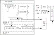
图2是本发明一实施例中机载处理器抗扰动控制方法框架示意图;FIG2 is a schematic diagram of a framework of an anti-disturbance control method for an airborne processor in one embodiment of the present invention;
图3是本发明一实施例中一种基于视觉的旋翼无人机抗扰动控制方法及系统的框架示意图;3 is a schematic diagram of a framework of a vision-based anti-disturbance control method and system for a rotary-wing UAV in one embodiment of the present invention;
图4是本发明一实施例中一种基于视觉的旋翼无人机抗扰动控制系统中各坐标系间的关系示意图;FIG4 is a schematic diagram of the relationship between various coordinate systems in a vision-based anti-disturbance control system for a rotary-wing UAV according to an embodiment of the present invention;
图5是本发明一实施例中一种基于视觉的旋翼无人机抗扰动控制系统的结构示意图。FIG5 is a schematic structural diagram of a vision-based anti-disturbance control system for a rotary-wing UAV in one embodiment of the present invention.
具体实施方式DETAILED DESCRIPTION
为了使本技术领域的人员更好地理解本发明的技术方案,下面结合附图对本发明作进一步的详细说明。In order to enable those skilled in the art to better understand the technical solution of the present invention, the present invention is further described in detail below in conjunction with the accompanying drawings.
一种基于视觉的旋翼无人机抗扰动控制方法,具体包括:A vision-based anti-disturbance control method for a rotary-wing UAV, specifically comprising:
S1、通过相机实时采集周围环境图像,通过飞行控制器中的惯性里程计实时采集旋翼无人机的角速度,机载处理器接收周围环境图像并处理得到单应性矩阵,根据单应性矩阵和预设的虚拟控制误差函数得到第一控制误差向量;S1, collecting the surrounding environment image in real time through the camera, collecting the angular velocity of the rotor UAV in real time through the inertial odometer in the flight controller, the onboard processor receives the surrounding environment image and processes it to obtain a homography matrix, and obtains a first control error vector according to the homography matrix and a preset virtual control error function;
S2、根据单应性矩阵设置扰动观测器,扰动观测器根据第一控制误差向量和角速度估计旋翼无人机的外部扰动量,外部扰动量包括外部扰动力和外部扰动力矩;S2. Setting a disturbance observer according to the homography matrix, wherein the disturbance observer estimates an external disturbance of the rotor UAV according to the first control error vector and the angular velocity, wherein the external disturbance includes an external disturbance force and an external disturbance torque;
S3、设置虚拟控制输入力,根据第一控制误差向量和虚拟控制输入力设置视觉外环控制器,将外部扰动力输入至视觉外环控制器,经过处理,得到期望推力,将期望推力通过机载处理器输出;S3, setting a virtual control input force, setting a visual outer loop controller according to the first control error vector and the virtual control input force, inputting an external disturbance force into the visual outer loop controller, obtaining a desired thrust after processing, and outputting the desired thrust through an onboard processor;
S4、根据虚拟控制输入力设置姿态内环控制器,将外部扰动力矩输入至姿态内环控制器,经过处理,得到期望控制力矩,将期望控制力矩通过机载处理器输出;S4, setting an attitude inner loop controller according to the virtual control input force, inputting the external disturbance torque into the attitude inner loop controller, obtaining the desired control torque after processing, and outputting the desired control torque through the onboard processor;
S5、飞行控制器接收机载处理器输出的期望推力和期望控制力矩,并根据期望推力和期望控制力矩控制旋翼无人机的鲁棒飞行。S5. The flight controller receives the desired thrust and the desired control torque output by the onboard processor, and controls the robust flight of the rotor UAV according to the desired thrust and the desired control torque.
具体地,参见图1、图2和图3,图1为本发明一实施例中一种基于视觉的旋翼无人机抗扰动控制方法的流程图;图2为本发明一实施例中机载处理器抗扰动控制方法框架示意图;图3为本发明一实施例中一种基于视觉的旋翼无人机抗扰动控制方法及系统的框架示意图。Specifically, referring to Figures 1, 2 and 3, Figure 1 is a flow chart of a vision-based anti-disturbance control method for a rotary-wing UAV in one embodiment of the present invention; Figure 2 is a framework schematic diagram of an anti-disturbance control method for an airborne processor in one embodiment of the present invention; Figure 3 is a framework schematic diagram of a vision-based anti-disturbance control method and system for a rotary-wing UAV in one embodiment of the present invention.
首先通过旋翼无人机上的相机实时采集周围环境图像,飞行控制器中的惯性里程计实时采集旋翼无人机的角速度,机载处理器接收周围环境图像并处理得到单应性矩阵,根据单应性矩阵和预设的虚拟控制误差函数得到第一控制误差向量;然后根据单应性矩阵设计扰动观测器,扰动观测器根据第一控制误差向量和角速度估计旋翼无人机的外部扰动量,外部扰动量包括外部扰动力和外部扰动力矩;接着设置虚拟控制输入力,根据第一控制误差向量和虚拟控制输入力设置视觉外环控制器,将外部扰动力输入视觉外环控制器,经过处理,得出期望推力;接着根据虚拟控制输入力设置姿态内环控制器,将外部扰动力矩输入姿态内环控制器,经过处理,得到期望控制力矩;扰动观测器、视觉外环控制器和姿态内环控制器均设置在机载处理器中,在旋翼无人机自主飞行途中,机载处理器通过不断地解算期望推力和期望控制力矩,同时将得到的期望推力和期望控制力矩输入飞行控制器中,飞行控制器对旋翼无人机进行姿态的控制,从而实现旋翼无人机的自主飞行。在该实施例中,带有惯性里程计的飞行控制器的型号为PX4。First, the camera on the rotor UAV collects the surrounding environment image in real time, the inertial odometer in the flight controller collects the angular velocity of the rotor UAV in real time, the onboard processor receives the surrounding environment image and processes it to obtain the homography matrix, and the first control error vector is obtained according to the homography matrix and the preset virtual control error function; then the disturbance observer is designed according to the homography matrix, and the disturbance observer estimates the external disturbance of the rotor UAV according to the first control error vector and the angular velocity, and the external disturbance includes the external disturbance force and the external disturbance torque; then the virtual control input force is set, and the visual outer loop control is set according to the first control error vector and the virtual control input force The controller inputs the external disturbance force into the visual outer loop controller, and after processing, the desired thrust is obtained; then the attitude inner loop controller is set according to the virtual control input force, and the external disturbance torque is input into the attitude inner loop controller, and after processing, the desired control torque is obtained; the disturbance observer, the visual outer loop controller and the attitude inner loop controller are all set in the airborne processor. During the autonomous flight of the rotor UAV, the airborne processor continuously solves the desired thrust and the desired control torque, and at the same time inputs the obtained desired thrust and the desired control torque into the flight controller, and the flight controller controls the attitude of the rotor UAV, thereby realizing the autonomous flight of the rotor UAV. In this embodiment, the model of the flight controller with inertial odometer is PX4.
在一个实施例中,S1中根据单应性矩阵和预设的虚拟控制误差函数得到第一控制误差向量,第一控制误差向量具体为:In one embodiment, in S1, a first control error vector is obtained according to the homography matrix and a preset virtual control error function. The first control error vector is specifically:

其中,
式中,


具体地,在求解得出图像间的单应性矩阵

式中,


在一个实施例中,S2中根据单应性矩阵设置扰动观测器,具体包括:In one embodiment, setting a disturbance observer according to the homography matrix in S2 specifically includes:
S21、根据单应性矩阵和旋翼无人机的数学模型设置旋翼无人机的视觉伺服模型;S21, setting a visual servo model of the rotary-wing UAV according to the homography matrix and the mathematical model of the rotary-wing UAV;
S22、重写旋翼无人机的视觉伺服模型,得到包含扰动的动力学模型;S22, rewrite the visual servo model of the rotary wing UAV to obtain a dynamic model including disturbances;
S23、设置包含扰动的动力学模型趋于稳定时对应的扰动观测器。S23. Setting a disturbance observer corresponding to when the dynamic model containing disturbance tends to be stable.
在一个实施例中,S23设置包含扰动的动力学模型趋于稳定时对应的扰动观测器,扰动观测器具体为:In one embodiment, S23 sets a disturbance observer corresponding to when the dynamic model containing the disturbance tends to be stable, and the disturbance observer is specifically:


其中,
式中,


具体地,根据单应性矩阵设置扰动观测器,过程如下:Specifically, the disturbance observer is set according to the homography matrix, and the process is as follows:
1)选取


其中,


参见图4,图4是本发明一实施例中一种基于视觉的旋翼无人机抗扰动控制系统中各坐标系间的关系示意图。Refer to FIG. 4 , which is a schematic diagram of the relationship between various coordinate systems in a vision-based anti-disturbance control system for a rotary-wing UAV in one embodiment of the present invention.
图4中示出了虚拟坐标系(


2)对旋翼无人机的视觉伺服模型进行重写,得到包含扰动的动力学模型:2) Rewrite the visual servo model of the rotorcraft to obtain a dynamic model including disturbances:

其中,


式中,


3)设置包含扰动的动力学模型趋于稳定时对应的扰动观测器:3) Set the disturbance observer corresponding to the dynamic model containing disturbances when it tends to be stable:


其中,
式中,


将第一控制误差向量和飞行控制器中惯性里程计读取的旋翼无人机的角速度输入至扰动观测器,经过处理,输出旋翼无人机的扰动量,扰动量包括扰动力和扰动力矩。The first control error vector and the angular velocity of the rotorcraft drone read by the inertial odometer in the flight controller are input into the disturbance observer, and after processing, the disturbance amount of the rotorcraft drone is output, and the disturbance amount includes the disturbance force and the disturbance torque.
扰动观测器输出的扰动力基于视觉特征构建,能够在有限的时间内收敛至外界扰动力真实值,扰动观测器输出的扰动力矩则根据角速度构建,能够在有限的时间内收敛至外界扰动力矩真实值。The disturbance force output by the disturbance observer is constructed based on visual features and can converge to the true value of the external disturbance force within a limited time. The disturbance torque output by the disturbance observer is constructed based on angular velocity and can converge to the true value of the external disturbance torque within a limited time.
实际测试中,

在一个实施例中,S3中根据第一控制误差向量和虚拟控制输入力设置视觉外环控制器,具体包括:In one embodiment, setting a visual outer loop controller according to the first control error vector and the virtual control input force in S3 specifically includes:
S31、根据第一控制误差向量构建第二控制误差向量;S31, constructing a second control error vector according to the first control error vector;
S32、分别对第一控制误差向量和第二控制误差向量求一阶导数,并结合虚拟控制力得到视觉外环动态方程;S32, respectively calculating the first-order derivatives of the first control error vector and the second control error vector, and combining the virtual control force to obtain the visual outer loop dynamic equation;
S33、设置视觉外环动态方程趋于稳定时对应的视觉外环控制器。S33, setting a corresponding visual outer loop controller when the visual outer loop dynamic equation tends to be stable.
在一个实施例中,S33设置视觉外环动态方程趋于稳定时对应的视觉外环控制器,视觉外环控制器具体为:In one embodiment, S33 sets a corresponding visual outer loop controller when the visual outer loop dynamic equation tends to be stable. The visual outer loop controller is specifically:

其中,
其中,


具体地,根据第一控制误差向量设置视觉外环控制器,根据视觉外环控制器计算得到期望推力,过程如下:Specifically, a visual outer loop controller is set according to the first control error vector, and the desired thrust is calculated according to the visual outer loop controller. The process is as follows:
1)基于反步法的思想,根据第一控制误差向量构建第二控制误差向量1) Based on the idea of backstepping, the second control error vector is constructed according to the first control error vector

式中,


预设虚拟控制输入力,分别对第一控制误差向量和第二控制控制误差向量求一阶导数,并结合预设的虚拟控制输入力得到视觉外环动态方程:The virtual control input force is preset, and the first-order derivatives of the first control error vector and the second control error vector are calculated respectively, and the visual outer loop dynamic equation is obtained by combining the preset virtual control input force:

式中,


3)设置视觉外环动态方程趋于稳定时对应的视觉外环控制器:3) Set the corresponding visual outer loop controller when the visual outer loop dynamic equation tends to be stable:

其中,


4)将扰动观测器输出的扰动力输入至视觉外环控制器,经过处理,得到期望推力:4) The disturbance force output by the disturbance observer is input into the visual outer loop controller, and after processing, the desired thrust is obtained:
将公式(7)代入公式(2)-3,并对公式(2)-3求导,得到期望推力的计算公式:Substituting formula (7) into formula (2)-3 and taking the derivative of formula (2)-3, we can obtain the calculation formula for the expected thrust:

式中,


其中,

在一个实施例中,S4中根据虚拟控制输入力设置姿态内环控制器,具体包括:In one embodiment, setting the attitude inner loop controller according to the virtual control input force in S4 specifically includes:
S41、根据虚拟控制输入力构建期望姿态矩阵;S41, constructing a desired posture matrix according to the virtual control input force;
S42、根据期望姿态矩阵在李群空间定义姿态误差向量和姿态角速度误差向量;S42, defining a posture error vector and a posture angular velocity error vector in a Lie group space according to the expected posture matrix;
S43、分别对姿态误差向量和姿态角速度误差向量求一阶导数,得到姿态内环动态方程;S43, respectively calculating the first-order derivatives of the attitude error vector and the attitude angular velocity error vector to obtain the attitude inner loop dynamic equation;
S44、根据姿态误差向量和姿态角速度误差向量设置滑膜面,结合姿态内环动态方程设置滑膜面趋于稳定时对应的姿态内环控制器。S44, setting a sliding film surface according to the attitude error vector and the attitude angular velocity error vector, and setting a corresponding attitude inner loop controller when the sliding film surface tends to be stable in combination with the attitude inner loop dynamic equation.
在一个实施例中,S44根据姿态误差向量和姿态角速度误差向量设置滑膜面,滑膜面具体为:In one embodiment, S44 sets a sliding film surface according to the attitude error vector and the attitude angular velocity error vector, and the sliding film surface is specifically:

其中,

式中,


在一个实施例中,S44结合姿态内环动态方程设置滑膜面趋于稳定时对应的姿态内环控制器,姿态内环控制器具体为:In one embodiment, S44 sets the attitude inner loop controller corresponding to when the sliding membrane surface tends to be stable in combination with the attitude inner loop dynamic equation. The attitude inner loop controller is specifically:

其中,


式中,


具体地,设置姿态内环控制器,根据姿态内环控制器计算出期望控制力矩,过程如下:Specifically, the attitude inner loop controller is set, and the desired control torque is calculated according to the attitude inner loop controller. The process is as follows:
1)用设置的虚拟控制输入力


其中,


式中,


2)在李群空间定义姿态误差向量和姿态角速度误差向量:2) Define the attitude error vector and attitude angular velocity error vector in Lie group space:


式中,


3)对姿态误差向量和姿态角速度误差向量分别求关于时间的一阶导数,得到姿态内环动态方程:3) Calculate the first-order derivative of the attitude error vector and the attitude angular velocity error vector with respect to time, and obtain the attitude inner loop dynamic equation:

式中,


4)根据姿态误差向量和姿态角速度误差向量设置滑膜面:4) Set the sliding membrane surface according to the attitude error vector and the attitude angular velocity error vector:

其中,

5)结合姿态内环动态方程,计算滑膜面快速稳定时(

其中,


式中,


为了解决滑膜控制过程中存在抖振问题,设置如下的自适应控制率:In order to solve the chattering problem in the synovial control process, the following adaptive control rate is set:

其中,


6)将扰动力矩输入姿态内环控制器,经过处理输出期望控制力矩。6) The disturbance torque is input into the attitude inner loop controller, and the desired control torque is output after processing.

在旋翼无人机自主飞行途中,不断的解算期望推力和力矩,同时将控制量输入控制器中,对旋翼无人机进行一个姿态的控制,从而实现旋翼无人机的自主飞行。During the autonomous flight of the rotorcraft UAV, the expected thrust and torque are continuously calculated, and the control quantity is input into the controller to control the posture of the rotorcraft UAV, thereby realizing the autonomous flight of the rotorcraft UAV.
一种基于视觉的旋翼无人机抗扰动控制系统,使用基于视觉的旋翼无人机抗扰动控制方法对旋翼无人机进行控制,系统包括:旋翼无人机、相机、机载处理器和飞行控制器,A vision-based anti-disturbance control system for a rotary-wing UAV uses a vision-based anti-disturbance control method for a rotary-wing UAV to control the rotary-wing UAV. The system includes: a rotary-wing UAV, a camera, an airborne processor, and a flight controller.
相机设置于旋翼无人机的正下方,用于实时采集周围环境图像;The camera is set directly below the rotor drone to collect images of the surrounding environment in real time;
飞行控制器设置于旋翼无人机上,飞行控制器包括惯性测量单元,惯性测量单元用于实时测量旋翼无人机的角速度;The flight controller is arranged on the rotor UAV, and the flight controller includes an inertial measurement unit, and the inertial measurement unit is used to measure the angular velocity of the rotor UAV in real time;
机载处理器设置于旋翼无人机上,机载处理器中设置了视觉外环控制器和姿态内环控制器,机载处理器通过视觉外环控制器和姿态内环控制器对周围环境图像和旋翼无人机的角速度进行处理,得到期望推力和期望控制力矩;The onboard processor is arranged on the rotor UAV, and a visual outer loop controller and an attitude inner loop controller are arranged in the onboard processor. The onboard processor processes the surrounding environment image and the angular velocity of the rotor UAV through the visual outer loop controller and the attitude inner loop controller to obtain the expected thrust and the expected control torque;
飞行控制器与机载处理器网络连接,用于接收机载处理器输出的期望推力和期望控制力矩,并通过期望推力和期望控制力矩控制旋翼无人机的飞行。The flight controller is connected to the onboard processor network, and is used for receiving the desired thrust and the desired control torque output by the onboard processor, and controlling the flight of the rotor UAV through the desired thrust and the desired control torque.
具体地,参见图5,图5为本发明一实施例中一种基于视觉的旋翼无人机抗扰动控制系统的结构示意图。Specifically, referring to FIG. 5 , FIG. 5 is a schematic structural diagram of a vision-based anti-disturbance control system for a rotary-wing UAV in one embodiment of the present invention.
一种基于视觉的旋翼无人机抗扰动控制系统,包括一架旋翼无人机4、飞行控制器3,相机2和机载处理器1;其中机载处理器1安装在旋翼无人机正上方,相机2需安装在旋翼无人机正下方且视野向下,其中摄像头的视野范围为90°,刷新频率为50HZ,图片像素大小为640×480。A vision-based anti-disturbance control system for a rotary-wing UAV includes a rotary-
相机2实时采集旋翼无人机4的周围环境图像,飞行控制器3中的惯性传感器实时采集旋翼无人机的角速度;The
机载处理器1接收旋翼无人机4的周围环境图像和角速度,经过处理输出期望推力和期望控制力矩;The
飞行控制器3根据机载处理器1输出的期望推力和期望控制力矩对旋翼无人机4进行控制。The
作为本实施例的一个改进,旋翼无人机平台选用阿木实验室的 JCV-600 无人机开发平台。As an improvement of this embodiment, the rotor UAV platform uses the JCV-600 UAV development platform of Amu Laboratory.
作为本实施例的一个改进,机载处理器1选用Intel 的 NUC11PAHi7卫星电脑。As an improvement of this embodiment, the
作为本实施例的一个改进,相机2选用大恒图像的 VEN-161 系列相机。As an improvement of this embodiment,
上述一种基于视觉抗扰动的旋翼无人机控制方法及系统,通过设计基于视觉特征的扰动观测器,可以快速精准的估计自身的受到的扰动量大小;提出了一种基于自适应滑膜理论的姿态内环控制器,通过姿态内环控制器输出的期望控制力矩可以快速控制旋翼无人机的姿态;利用单应性特征法作为基础,相较于采用特征和光流等方法,其具有更强的鲁棒性和更高的效率。该方法控制的旋翼无人机能够在外界存在扰动的条件下稳定运行,仅由旋翼无人机自身的机载处理器进行自主控制,相比于传统的控制方法,该方法对场景具有很强的鲁棒性,即使在更复杂环境的条件下也能实现自主飞行。The above-mentioned control method and system of a rotor UAV based on visual anti-disturbance can quickly and accurately estimate the magnitude of the disturbance it receives by designing a disturbance observer based on visual features; an attitude inner loop controller based on adaptive sliding film theory is proposed, and the attitude of the rotor UAV can be quickly controlled by the expected control torque output by the attitude inner loop controller; it uses the homography feature method as the basis, and has stronger robustness and higher efficiency than methods such as feature and optical flow. The rotor UAV controlled by this method can operate stably under the condition of external disturbances, and is autonomously controlled only by the rotor UAV's own onboard processor. Compared with traditional control methods, this method has strong robustness to the scene and can achieve autonomous flight even in more complex environments.
以上对本发明所提供的一种基于视觉的旋翼无人机抗扰动控制方法进行了详细介绍。本文中应用了具体个例对本发明的原理及实施方式进行了阐述,以上实施例的说明只是用于帮助理解本发明的核心思想。应当指出,对于本技术领域的普通技术人员来说,在不脱离本发明原理的前提下,还可以对本发明进行若干改进和修饰,这些改进和修饰也落入本发明权利要求的保护范围内。The above is a detailed introduction to the vision-based anti-disturbance control method for a rotary-wing UAV provided by the present invention. This article uses specific examples to illustrate the principles and implementation methods of the present invention. The description of the above embodiments is only used to help understand the core idea of the present invention. It should be pointed out that for ordinary technicians in this technical field, without departing from the principles of the present invention, several improvements and modifications can be made to the present invention, and these improvements and modifications also fall within the scope of protection of the claims of the present invention.
Claims (10)
Translated fromChinese


Priority Applications (1)
| Application Number | Priority Date | Filing Date | Title |
|---|---|---|---|
| CN202310443703.0ACN116149193B (en) | 2023-04-24 | 2023-04-24 | Anti-disturbance control method and system for rotor unmanned aerial vehicle based on vision |
Applications Claiming Priority (1)
| Application Number | Priority Date | Filing Date | Title |
|---|---|---|---|
| CN202310443703.0ACN116149193B (en) | 2023-04-24 | 2023-04-24 | Anti-disturbance control method and system for rotor unmanned aerial vehicle based on vision |
Publications (2)
| Publication Number | Publication Date |
|---|---|
| CN116149193A CN116149193A (en) | 2023-05-23 |
| CN116149193Btrue CN116149193B (en) | 2023-06-23 |
Family
ID=86352906
Family Applications (1)
| Application Number | Title | Priority Date | Filing Date |
|---|---|---|---|
| CN202310443703.0AActiveCN116149193B (en) | 2023-04-24 | 2023-04-24 | Anti-disturbance control method and system for rotor unmanned aerial vehicle based on vision |
Country Status (1)
| Country | Link |
|---|---|
| CN (1) | CN116149193B (en) |
Families Citing this family (3)
| Publication number | Priority date | Publication date | Assignee | Title |
|---|---|---|---|---|
| CN116643501B (en)* | 2023-07-18 | 2023-10-24 | 湖南大学 | Variable impedance control method and system for aerial working robot under stability constraint |
| CN118778681A (en)* | 2024-09-06 | 2024-10-15 | 北京卓翼智能科技有限公司 | UAV companion flight method, device, UAV and storage medium |
| CN119126846B (en)* | 2024-11-13 | 2025-02-18 | 江西省军民融合研究院 | UAV precise location landing method and system based on image recognition analysis |
Citations (7)
| Publication number | Priority date | Publication date | Assignee | Title |
|---|---|---|---|---|
| EP1901153A1 (en)* | 2006-09-12 | 2008-03-19 | OFFIS e.V. | Control system for unmanned 4-rotor-helicopter |
| CN113138608A (en)* | 2021-05-10 | 2021-07-20 | 新疆大学 | Four-rotor unmanned aerial vehicle visual servo control method using disturbance observer and nonlinear speed observer |
| CN113189875A (en)* | 2021-04-29 | 2021-07-30 | 湖南大学 | Unmanned aerial vehicle robust landing method on mobile platform based on circular features |
| CN113359472A (en)* | 2021-07-02 | 2021-09-07 | 北京理工大学 | Adaptive robust trajectory tracking control method for quad-rotor unmanned aerial vehicle |
| CN114089779A (en)* | 2021-11-24 | 2022-02-25 | 湖南大学 | Aerial robot vision autonomous control method and system in GPS-denied environment |
| CN115366109A (en)* | 2022-09-23 | 2022-11-22 | 北京航空航天大学杭州创新研究院 | Composite layered anti-interference method for rotor flight mechanical arm |
| CN115480583A (en)* | 2022-09-22 | 2022-12-16 | 福州大学 | Visual Servo Tracking and Impedance Control Method for Flying Robot |
Family Cites Families (1)
| Publication number | Priority date | Publication date | Assignee | Title |
|---|---|---|---|---|
| US10520943B2 (en)* | 2016-08-12 | 2019-12-31 | Skydio, Inc. | Unmanned aerial image capture platform |
- 2023
- 2023-04-24CNCN202310443703.0Apatent/CN116149193B/enactiveActive
Patent Citations (7)
| Publication number | Priority date | Publication date | Assignee | Title |
|---|---|---|---|---|
| EP1901153A1 (en)* | 2006-09-12 | 2008-03-19 | OFFIS e.V. | Control system for unmanned 4-rotor-helicopter |
| CN113189875A (en)* | 2021-04-29 | 2021-07-30 | 湖南大学 | Unmanned aerial vehicle robust landing method on mobile platform based on circular features |
| CN113138608A (en)* | 2021-05-10 | 2021-07-20 | 新疆大学 | Four-rotor unmanned aerial vehicle visual servo control method using disturbance observer and nonlinear speed observer |
| CN113359472A (en)* | 2021-07-02 | 2021-09-07 | 北京理工大学 | Adaptive robust trajectory tracking control method for quad-rotor unmanned aerial vehicle |
| CN114089779A (en)* | 2021-11-24 | 2022-02-25 | 湖南大学 | Aerial robot vision autonomous control method and system in GPS-denied environment |
| CN115480583A (en)* | 2022-09-22 | 2022-12-16 | 福州大学 | Visual Servo Tracking and Impedance Control Method for Flying Robot |
| CN115366109A (en)* | 2022-09-23 | 2022-11-22 | 北京航空航天大学杭州创新研究院 | Composite layered anti-interference method for rotor flight mechanical arm |
Non-Patent Citations (4)
| Title |
|---|
| 《An onboard-eye-to-hand visual servo and task coordination control for aerial manipulator based on a spherical model》;Ningbin Lai等;《Mechatronics》(第82期);第1-11页* |
| 《Dynamic Image-Based Visual Servoing of Unmanned Aerial Vehicles under Disturbances》;Yanjie Chen等;《Advanced Robotics and Mechatronics》;第31-36页* |
| 旋翼飞行机械臂的混合视觉伺服和分层控制方法;孙敬陶;钟杭;王耀南;李希;;仪器仪表学报(第07期);第56-65页* |
| 旋翼飞行机械臂系统的混合视觉伺服控制;孙敬陶;王耀南;谭建豪;钟杭;李瑞涵;;控制理论与应用(第04期);第505-515页* |
Also Published As
| Publication number | Publication date |
|---|---|
| CN116149193A (en) | 2023-05-23 |
Similar Documents
| Publication | Publication Date | Title |
|---|---|---|
| CN116149193B (en) | Anti-disturbance control method and system for rotor unmanned aerial vehicle based on vision | |
| Shraim et al. | A survey on quadrotors: Configurations, modeling and identification, control, collision avoidance, fault diagnosis and tolerant control | |
| Dhadekar et al. | Robust control of quadrotor using uncertainty and disturbance estimation | |
| EP3111286B1 (en) | Aircraft attitude control methods | |
| Derafa et al. | Super twisting control algorithm for the attitude tracking of a four rotors UAV | |
| Lin et al. | A decoupling control for quadrotor UAV using dynamic surface control and sliding mode disturbance observer | |
| Leong et al. | Low-cost microcontroller-based hover control design of a quadcopter | |
| WO2019024303A1 (en) | Stable flight control method for multi-rotor unmanned aerial vehicle based on finite-time neurodynamics | |
| EP3529683A1 (en) | Thrust vectored multicopters | |
| Bannwarth et al. | Disturbance accomodation control for wind rejection of a quadcopter | |
| CN106292297B (en) | Attitude control method based on PID controller and L1 adaptive controller | |
| Zhou et al. | Station-keeping control of an underactuated stratospheric airship | |
| CN114564038A (en) | Improved active disturbance rejection based trajectory tracking control system for quad-rotor unmanned aerial vehicle | |
| Nemati et al. | Control of microcoaxial helicopter based on a reduced-order observer | |
| Mokhtari et al. | Sliding mode control for a small coaxial rotorcraft UAV | |
| CN110888447B (en) | Four-rotor-wing 3D path tracking method based on nonlinear PD double closed-loop control | |
| Haocong et al. | Design of stm32-based quadrotor UAV control system | |
| Artale et al. | Dynamic analysis of a hexacopter controlled via LQR-PI | |
| Moonumca et al. | Adaptive PID for controlling a quadrotor in a virtual outdoor scenario: Simulation study | |
| Kemper et al. | Impact of center of gravity in quadrotor helicopter controller design | |
| CN109656258A (en) | A decoupling stabilization control method for flight altitude and flight attitude of a small unmanned aerial vehicle | |
| Fethalla | Modelling, identification, and control of a quadrotor helicopter | |
| Martínez-Vásquez et al. | Linear observer for estimating wind gust in UAV's | |
| CN114089779B (en) | Autonomous control method and system for vision of aerial robot in GPS refusing environment | |
| Ceren et al. | Vision-based servo control of a quadrotor air vehicle |
Legal Events
| Date | Code | Title | Description |
|---|---|---|---|
| PB01 | Publication | ||
| PB01 | Publication | ||
| SE01 | Entry into force of request for substantive examination | ||
| SE01 | Entry into force of request for substantive examination | ||
| GR01 | Patent grant | ||
| GR01 | Patent grant |