CN116148970A - Optical module and display device - Google Patents
Optical module and display deviceDownload PDFInfo
- Publication number
- CN116148970A CN116148970ACN202310156485.2ACN202310156485ACN116148970ACN 116148970 ACN116148970 ACN 116148970ACN 202310156485 ACN202310156485 ACN 202310156485ACN 116148970 ACN116148970 ACN 116148970A
- Authority
- CN
- China
- Prior art keywords
- coupling
- section
- light
- waveguide
- outcoupling
- Prior art date
- Legal status (The legal status is an assumption and is not a legal conclusion. Google has not performed a legal analysis and makes no representation as to the accuracy of the status listed.)
- Pending
Links
- 230000003287optical effectEffects0.000titleclaimsabstractdescription84
- 239000011159matrix materialSubstances0.000claimsabstractdescription16
- 238000010168coupling processMethods0.000claimsdescription87
- 238000005859coupling reactionMethods0.000claimsdescription87
- 230000008878couplingEffects0.000claimsdescription80
- 230000008859changeEffects0.000claimsdescription15
- 230000000712assemblyEffects0.000abstract1
- 238000000429assemblyMethods0.000abstract1
- 239000000758substrateSubstances0.000description19
- 238000010586diagramMethods0.000description12
- 238000000034methodMethods0.000description11
- 239000000463materialSubstances0.000description6
- 230000008569processEffects0.000description5
- 230000000694effectsEffects0.000description4
- 239000011521glassSubstances0.000description4
- VYPSYNLAJGMNEJ-UHFFFAOYSA-NSilicium dioxideChemical compoundO=[Si]=OVYPSYNLAJGMNEJ-UHFFFAOYSA-N0.000description2
- 230000003190augmentative effectEffects0.000description2
- 230000005540biological transmissionEffects0.000description2
- 238000005516engineering processMethods0.000description2
- 238000012986modificationMethods0.000description2
- 230000004048modificationEffects0.000description2
- 229920002120photoresistant polymerPolymers0.000description2
- 239000012780transparent materialSubstances0.000description2
- 229910052681coesiteInorganic materials0.000description1
- 229910052906cristobaliteInorganic materials0.000description1
- 238000005530etchingMethods0.000description1
- 210000003128headAnatomy0.000description1
- 238000009434installationMethods0.000description1
- 238000000025interference lithographyMethods0.000description1
- 229910001635magnesium fluorideInorganic materials0.000description1
- 230000000644propagated effectEffects0.000description1
- 230000001902propagating effectEffects0.000description1
- 230000001105regulatory effectEffects0.000description1
- 239000011347resinSubstances0.000description1
- 229920005989resinPolymers0.000description1
- 239000000377silicon dioxideSubstances0.000description1
- 235000012239silicon dioxideNutrition0.000description1
- 239000004984smart glassSubstances0.000description1
- 229910052682stishoviteInorganic materials0.000description1
- 229910052905tridymiteInorganic materials0.000description1
- 230000000007visual effectEffects0.000description1
Images


Classifications
- G—PHYSICS
- G02—OPTICS
- G02B—OPTICAL ELEMENTS, SYSTEMS OR APPARATUS
- G02B6/00—Light guides; Structural details of arrangements comprising light guides and other optical elements, e.g. couplings
- G02B6/0001—Light guides; Structural details of arrangements comprising light guides and other optical elements, e.g. couplings specially adapted for lighting devices or systems
- G02B6/0011—Light guides; Structural details of arrangements comprising light guides and other optical elements, e.g. couplings specially adapted for lighting devices or systems the light guides being planar or of plate-like form
- G02B6/0033—Means for improving the coupling-out of light from the light guide
- G02B6/005—Means for improving the coupling-out of light from the light guide provided by one optical element, or plurality thereof, placed on the light output side of the light guide
- G—PHYSICS
- G02—OPTICS
- G02B—OPTICAL ELEMENTS, SYSTEMS OR APPARATUS
- G02B27/00—Optical systems or apparatus not provided for by any of the groups G02B1/00 - G02B26/00, G02B30/00
- G02B27/01—Head-up displays
- G02B27/017—Head mounted
- G02B27/0172—Head mounted characterised by optical features
- G—PHYSICS
- G02—OPTICS
- G02B—OPTICAL ELEMENTS, SYSTEMS OR APPARATUS
- G02B5/00—Optical elements other than lenses
- G02B5/18—Diffraction gratings
- G02B5/1814—Diffraction gratings structurally combined with one or more further optical elements, e.g. lenses, mirrors, prisms or other diffraction gratings
- G02B5/1819—Plural gratings positioned on the same surface, e.g. array of gratings
- G—PHYSICS
- G02—OPTICS
- G02B—OPTICAL ELEMENTS, SYSTEMS OR APPARATUS
- G02B5/00—Optical elements other than lenses
- G02B5/18—Diffraction gratings
- G02B5/1842—Gratings for image generation
- G—PHYSICS
- G02—OPTICS
- G02B—OPTICAL ELEMENTS, SYSTEMS OR APPARATUS
- G02B5/00—Optical elements other than lenses
- G02B5/18—Diffraction gratings
- G02B5/1866—Transmission gratings characterised by their structure, e.g. step profile, contours of substrate or grooves, pitch variations, materials
- G—PHYSICS
- G02—OPTICS
- G02B—OPTICAL ELEMENTS, SYSTEMS OR APPARATUS
- G02B27/00—Optical systems or apparatus not provided for by any of the groups G02B1/00 - G02B26/00, G02B30/00
- G02B27/01—Head-up displays
- G02B27/017—Head mounted
- G02B2027/0178—Eyeglass type
Landscapes
- Physics & Mathematics (AREA)
- General Physics & Mathematics (AREA)
- Optics & Photonics (AREA)
- Optical Integrated Circuits (AREA)
- Optical Couplings Of Light Guides (AREA)
Abstract
Description
Translated fromChinese技术领域technical field
本申请属于光学组件技术领域,具体涉及一种光学组件和显示装置。The present application belongs to the technical field of optical components, and in particular relates to an optical component and a display device.
背景技术Background technique
相关技术中,光学组件是用于将图像信号引导至人眼的一种光学组件,光学组件在各类显示装置中被广泛应用,例如,光学组件常被应用于AR眼镜、VR眼镜、全息显示设备以及可穿戴式智能显示设备等显示装置,让用户可以较为直观的体会虚拟世界的图像,增强了用户的视觉体验。In related technologies, an optical component is an optical component used to guide image signals to the human eye. Optical components are widely used in various display devices. For example, optical components are often used in AR glasses, VR glasses, holographic displays Devices and wearable smart display devices and other display devices allow users to experience the images of the virtual world more intuitively and enhance the user's visual experience.
目前,有许多光学组件利用波导基体的全反射特性以及衍射光栅的衍射特性来引导图像信号传播至人眼。但是,随着光在耦出光栅与波导基体间不断发生出射和全反射,使得从耦出光栅不同位置处出射的光的能量不相同,从而使得从光学组件中射出的光的分布均匀性较低,降低了用户的体验效果。At present, there are many optical components that use the total reflection properties of the waveguide substrate and the diffraction properties of the diffraction grating to guide the image signal to propagate to the human eye. However, as the light continuously exits and is totally reflected between the outcoupling grating and the waveguide substrate, the energy of the light exiting from different positions of the outcoupling grating is different, so that the distribution uniformity of the light exiting from the optical component is relatively small. Low, reducing the user experience effect.
发明内容Contents of the invention
本申请旨在提供一种光学组件和显示装置,至少解决从光学组件中射出的光分布均匀性较低的技术问题。The present application aims to provide an optical component and a display device, at least solving the technical problem of low uniformity of light distribution emitted from the optical component.
为了解决上述技术问题,本申请是这样实现的:In order to solve the above-mentioned technical problems, the application is implemented as follows:
第一方面,本申请实施例提供了一种光学组件,光学组件包括波导基体、耦入件、耦出件以及达曼光栅,波导基体包括耦入段、耦出段以及连接于耦入段与耦出段间的波导段,耦入段用于接收光,波导段用于传播从耦入段内接收的光至耦出段,光从耦出段中射出;耦入件设置于耦入段,耦入件用于改变光的传播方向,以使得光从耦入段传播至波导段并通过波导段进入耦出段;耦出件设置于耦出段在第一方向上的一侧;达曼光栅设置于耦出段在第一方向上远离耦出件的一侧,达曼光栅使得穿过达曼光栅的光在第二方向与第三方向上阵列排布,其中,耦出件用于改变光的传播方向,以使得进入耦出段内的光沿第一方向传播至达曼光栅处,第一方向、第二方向与第三方向两两相交。In the first aspect, the embodiment of the present application provides an optical component. The optical component includes a waveguide base, a coupling element, an outcoupling element, and a Damman grating. The waveguide base includes an incoupling section, an outcoupling section, and a The waveguide section between the outcoupling sections, the incoupling section is used to receive light, the waveguide section is used to propagate the light received from the incoupling section to the outcoupling section, and the light is emitted from the outcoupling section; the coupling part is arranged in the coupling section , the coupling element is used to change the propagation direction of the light, so that the light propagates from the coupling section to the waveguide section and enters the outcoupling section through the waveguide section; the outcoupling element is arranged on one side of the outcoupling section in the first direction; The outcoupling section is arranged on the side of the outcoupling section away from the outcoupling element in the first direction, and the Damman grating makes the light passing through the Damman grating arranged in an array in the second direction and the third direction, wherein the outcoupling element is used for The propagation direction of the light is changed so that the light entering the outcoupling section propagates to the Damman grating along the first direction, and the first direction, the second direction and the third direction intersect two by two.
第二方面,本申请还提供了一种显示装置,显示装置包括光源以及如第一方面提供的光学组件,光源用于将光射入耦入段或耦入件。In a second aspect, the present application further provides a display device, the display device includes a light source and the optical assembly as provided in the first aspect, and the light source is used to inject light into the coupling section or the coupling element.
在本申请提供的光学组件中,光学组件包括波导基体、耦入件、耦出件以及达曼光栅,耦入件设置于耦入段,耦入件能够用于改变光的传播方向,使得入射至耦入件的光在受耦入件的影响并射离耦入件后能够被改变传播方向,从而使得光能够从波导基体的耦入段传播至波导段并在波导段内发生反射,在波导段内发生反射的光能够继续被传播至耦入段。耦出件与达曼光栅分设于耦出段在第一方向上的两侧,耦出件能够用于接收进入至耦入段的光并改变光的传播方向,使得入射至耦出件的光在受耦出件的影响并射离耦出件后能够被改变传播方向,从而使得光能够朝向达曼光栅进行传播。达曼光栅为二维光栅,射离耦出件的光在穿过达曼光栅后能够在第二方向与第三方向上阵列分布,提高了从光学组件中射出的光的均匀性,增强了用户的体验效果。In the optical assembly provided in this application, the optical assembly includes a waveguide base, a coupling element, an outcoupling element, and a Damman grating. The light to the coupling element can be changed in the direction of propagation after being affected by the coupling element and exiting the coupling element, so that the light can propagate from the coupling section of the waveguide substrate to the waveguide section and reflect in the waveguide section. Light reflected in the waveguide section can continue to propagate to the incoupling section. The outcoupling element and the Damman grating are separately arranged on both sides of the outcoupling section in the first direction, and the outcoupling element can be used to receive the light entering the incoupling section and change the propagation direction of the light so that the light incident on the outcoupling element After being affected by the outcoupling element and exiting the outcoupling element, it can be redirected so that the light can propagate towards the Damman grating. The Damman grating is a two-dimensional grating. After passing through the Damman grating, the light emitted from the outcoupling can be arrayed in the second direction and the third direction, which improves the uniformity of the light emitted from the optical component and enhances the user experience. experience effect.
本申请的附加方面和优点将在下面的描述中部分给出,部分将从下面的描述中变得明显,或通过本申请的实践了解到。Additional aspects and advantages of the application will be set forth in part in the description which follows, and in part will be obvious from the description, or may be learned by practice of the application.
附图说明Description of drawings
为了更清楚地说明本申请实施例的技术方案,下面将对本申请实施例中所需要使用的附图作简单地介绍,显而易见地,下面所描述的附图仅仅是本申请的一些实施例,对于本领域普通技术人员来讲,在不付出创造性劳动的前提下,还可以根据这些附图获得其他的附图,其中:In order to more clearly illustrate the technical solutions of the embodiments of the present application, the following will briefly introduce the accompanying drawings that need to be used in the embodiments of the present application. Obviously, the accompanying drawings described below are only some embodiments of the present application. Those of ordinary skill in the art can also obtain other drawings based on these drawings without any creative effort, in which:
图1为本申请一些实施例的光学组件的结构示意图;Fig. 1 is a schematic structural diagram of an optical assembly of some embodiments of the present application;
图2为本申请一些实施例的光学组件的剖视示意图;2 is a schematic cross-sectional view of an optical assembly of some embodiments of the present application;
图3为本申请一些实施例的达曼光栅与落在参考平面上的第一正投影的示意图;3 is a schematic diagram of a Damman grating and a first orthographic projection falling on a reference plane in some embodiments of the present application;
图4为本申请另一些实施例的达曼光栅与落在参考平面上的第一正投影的示意图;Fig. 4 is a schematic diagram of the Damman grating and the first orthographic projection falling on the reference plane in other embodiments of the present application;
图5为本申请一些实施例的落在参考平面上的光点的示意图;5 is a schematic diagram of light spots falling on a reference plane according to some embodiments of the present application;
图6为本申请另一些实施例的落在参考平面上的光点的示意图;FIG. 6 is a schematic diagram of light spots falling on a reference plane according to other embodiments of the present application;
图7为本申请另一些实施例的光学组件的剖视示意图;FIG. 7 is a schematic cross-sectional view of optical components in other embodiments of the present application;
图8为本申请又一些实施例的光学组件的剖视示意图;Fig. 8 is a schematic cross-sectional view of an optical assembly according to some other embodiments of the present application;
图9为本申请再一些实施例的光学组件的剖视示意图;FIG. 9 is a schematic cross-sectional view of an optical assembly in some other embodiments of the present application;
图10为本申请再一些实施例的光学组件的剖视示意图;Fig. 10 is a schematic cross-sectional view of an optical assembly according to some other embodiments of the present application;
图11为本申请一些实施例的光学组件的局部剖视图;Fig. 11 is a partial cross-sectional view of an optical assembly according to some embodiments of the present application;
图12为本申请另一些实施例的光学组件的局部剖视示意图;Fig. 12 is a partial cross-sectional schematic diagram of optical components in other embodiments of the present application;
图13为本申请又一些实施例的光学组件的局部剖视示意图;Fig. 13 is a partial cross-sectional schematic diagram of an optical assembly according to some other embodiments of the present application;
图14为本申请一些实施例的显示装置的剖视示意图。FIG. 14 is a schematic cross-sectional view of a display device according to some embodiments of the present application.
附图标记说明:Explanation of reference signs:
10-显示装置;10 - display device;
1-光学组件;11-波导基体;111-耦入段;111a-入光侧;111b-非入光侧;112-波导段;113-耦出段;113a-出光侧;113b-非出光侧;12-耦入件;13-耦出件;14-达曼光栅;141-第一相位部;142-第二相位部;143-第一正投影;143a-第一侧边;143b-第二侧边;143c-第三侧边;143d-第四侧边;143e-第一分割边;143f-第二分割边;143g-第一子投影;143h-第二子投影;143i-第三子投影;143j-第四子投影;144-主体部;1-optical component; 11-waveguide substrate; 111-coupling section; 111a-incoming side; 111b-non-incoming side; 112-waveguide section; 113-outcoupling section; ; 12-coupler; 13-coupler; 14-Daman grating; 141-first phase part; 143c-third side; 143d-fourth side; 143e-first split side; 143f-second split side; 143g-first sub-projection; 143h-second sub-projection; 143i-third Sub-projection; 143j-the fourth sub-projection; 144-main body;
2-光点;2 - light spot;
3-光源;3 - light source;
4-准直系统;4-collimation system;
X-第一方向;X - first direction;
Y-第二方向;Y - the second direction;
Z-第三方向;Z - third direction;
P-参考平面;P - reference plane;
i-衍射角度;i - diffraction angle;
k-预设角度。k - preset angle.
具体实施方式Detailed ways
下面将详细描述本申请的各个方面的特征和示例性实施例,为了使本申请的目的、技术方案及优点更加清楚明白,以下结合附图及具体实施例,对本申请进行进一步详细描述。应理解,此处所描述的具体实施例仅意在解释本申请,而不是限定本申请。对于本领域技术人员来说,本申请可以在不需要这些具体细节中的一些细节的情况下实施。下面对实施例的描述仅仅是为了通过示出本申请的示例来提供对本申请更好的理解,在附图和下面的描述中,至少部分的公知结构和技术没有被示出,以便避免对本申请造成不必要的模糊;并且,为了清晰,可能夸大了部分结构的尺寸。此外,下文中所描述的特征、结构或特性可以以任何合适的方式结合在一个或更多实施例中。The characteristics and exemplary embodiments of various aspects of the application will be described in detail below. In order to make the purpose, technical solution and advantages of the application clearer, the application will be further described in detail below in conjunction with the accompanying drawings and specific embodiments. It should be understood that the specific embodiments described here are only intended to explain the present application rather than limit the present application. It will be apparent to one skilled in the art that the present application may be practiced without some of these specific details. The following description of the embodiments is only to provide a better understanding of the present application by showing examples of the present application. In the drawings and the following description, at least part of the known structures and techniques are not shown in order to avoid misunderstanding of the present application. Application creates unnecessary obscurity; and, for clarity, the dimensions of some structures may be exaggerated. Furthermore, the features, structures, or characteristics described hereinafter may be combined in any suitable manner in one or more embodiments.
需要说明的是,在本文中,除非另有说明,“多个”的含义是两个以上;术语“上”、“下”、“左”、“右”、“内”、“外”等指示的方位或位置关系仅是为了便于描述本申请和简化描述,而不是指示或暗示所指的装置或元件必须具有特定的方位、以特定的方位构造和操作,因此不能理解为对本申请的限制。此外,诸如第一和第二等之类的关系术语仅仅用来将一个实体或者操作与另一个实体或操作区分开来,而不一定要求或者暗示这些实体或操作之间存在任何这种实际的关系或者顺序。而且,术语“包括”、“包含”或者其任何其他变体意在涵盖非排他性的包含,从而使得包括一系列要素的过程、方法、物品或者设备不仅包括那些要素,而且还包括没有明确列出的其他要素,或者是还包括为这种过程、方法、物品或者设备所固有的要素。在没有更多限制的情况下,由语句“包括……”限定的要素,并不排除在包括所述要素的过程、方法、物品或者设备中还存在另外的相同要素。It should be noted that, in this article, unless otherwise stated, "plurality" means more than two; the terms "upper", "lower", "left", "right", "inner", "outer", etc. The indicated orientation or positional relationship is only for the convenience of describing the present application and simplifying the description, rather than indicating or implying that the referred device or element must have a specific orientation, be constructed and operated in a specific orientation, and therefore cannot be construed as limiting the application . Furthermore, relational terms such as first and second, etc., are used merely to distinguish one entity or operation from another without necessarily requiring or implying that any such actual relationship between the entities or operations exists. relationship or sequence. Furthermore, the term "comprises", "comprises" or any other variation thereof is intended to cover a non-exclusive inclusion such that a process, method, article, or apparatus comprising a set of elements includes not only those elements, but also includes elements not expressly listed. other elements of or also include elements inherent in such a process, method, article, or device. Without further limitations, an element defined by the statement "comprising..." does not exclude the presence of additional same elements in the process, method, article or device comprising said element.
下述描述中出现的方位词均为图中示出的方向,并不是对本申请的实施例的具体结构进行限定。在本申请的描述中,还需要说明的是,除非另有明确的规定和限定,术语“安装”、“连接”应做广义理解,例如,可以是固定连接,也可以是可拆卸连接,或一体地连接;可以是直接相连,也可以间接相连。对于本领域的普通技术人员而言,可视具体情况理解上述术语在本申请中的具体含义。The orientation words appearing in the following description are the directions shown in the figure, and do not limit the specific structure of the embodiment of the present application. In the description of this application, it should also be noted that unless otherwise specified and limited, the terms "installation" and "connection" should be understood in a broad sense, for example, it can be a fixed connection or a detachable connection, or Connected integrally; either directly or indirectly. For those of ordinary skill in the art, the specific meanings of the above terms in this application can be understood according to specific situations.
相关技术中,有许多光学组件利用波导基体的全反射特性以及衍射光栅的衍射特性来引导图像信号传播至人眼。申请人研究发现,由于大部分的光学组件需要对光进行一维或二维的扩展,即进入光学组件的光往往需要在光学组件内的耦出光栅与波导基体间不断发生出射和全反射,以使得光能够从耦出光栅的不同位置处射出,从而实现对光的一维或二维的扩展,使得射出光学组件的光具有较大的视场角,但是,从耦出光栅不同位置处出射的光的能量不相同,从而使得从光学组件中射出的光的分布均匀性较低,降低了用户的体验效果。In the related art, there are many optical components that use the total reflection property of the waveguide substrate and the diffraction property of the diffraction grating to guide the image signal to propagate to the human eye. The applicant's research found that since most optical components need to expand the light in one or two dimensions, that is, the light entering the optical component often needs to be emitted and totally reflected between the outcoupling grating in the optical component and the waveguide substrate. In order to enable the light to be emitted from different positions of the outcoupling grating, so as to realize the one-dimensional or two-dimensional expansion of the light, so that the light exiting the optical component has a larger field of view, but from different positions of the outcoupling grating The energy of the emitted light is different, so that the distribution uniformity of the light emitted from the optical component is low, which reduces the experience effect of the user.
为了解决上述技术问题,提供了本申请。为了更好地理解本申请,下面结合附图对本申请实施例的光学组件和显示装置进行详细描述。In order to solve the above technical problems, the present application is provided. In order to better understand the present application, the optical assembly and the display device according to the embodiments of the present application will be described in detail below with reference to the accompanying drawings.
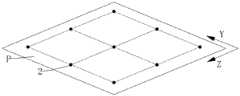
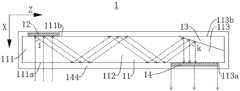
图1为本申请一些实施例的光学组件1的结构示意图,图2为本申请一些实施例的光学组件1的剖视示意图,图中X方向为第一方向,图中Y方向为第二方向,图中Z方向为第三方向,图1与图2中虚线路径表示光的路径。Fig. 1 is a schematic structural view of an
如图1与图2所示,本申请实施例提供了一种光学组件1,光学组件1包括波导基体11、耦入件12、耦出件13以及达曼光栅14,波导基体11包括耦入段111、耦出段113以及连接于耦入段111与耦出段113间的波导段112,耦入段111用于接收光,波导段112用于传播从耦入段111内接收的光至耦出段113,光从耦出段113中射出;耦入件12设置于耦入段111,耦入件12用于改变光的传播方向,以使得光从耦入段111传播至波导段112并通过波导段112进入耦出段113;耦出件13设置于耦出段113在第一方向X上的一侧;达曼光栅14设置于耦出段113在第一方向X上远离耦出件13的一侧,达曼光栅14使得穿过达曼光栅14的光在第二方向Y与第三方向Z上阵列排布,其中,耦出件13用于改变光的传播方向,以使得进入耦出段113内的光沿第一方向X传播至达曼光栅14处,第一方向X、第二方向Y与第三方向Z两两相交。As shown in Figure 1 and Figure 2, the embodiment of the present application provides an optical component 1, the optical component 1 includes a waveguide substrate 11, a coupling element 12, a coupling element 13 and a Damman grating 14, the waveguide substrate 11 includes a coupling element Section 111, outcoupling section 113 and waveguide section 112 connected between incoupling section 111 and outcoupling section 113, incoupling section 111 is used for receiving light, and waveguide section 112 is used for propagating light received from incoupling section 111 to Outcoupling section 113, light is emitted from outcoupling section 113; coupling element 12 is arranged on coupling section 111, and coupling element 12 is used to change the propagation direction of light, so that light propagates from coupling section 111 to waveguide section 112 And enter the outcoupling section 113 through the waveguide section 112; the outcoupling member 13 is arranged on one side of the outcoupling section 113 in the first direction X; the Daman grating 14 is arranged in the outcoupling section 113 away from the outcoupling section 113 in the first direction X On one side of the element 13, the Damman grating 14 makes the light passing through the Damman grating 14 arrayed in the second direction Y and the third direction Z, wherein the outcoupling element 13 is used to change the propagation direction of the light, so that The light entering the outcoupling section 113 propagates to the Damman grating 14 along the first direction X, and the first direction X, the second direction Y and the third direction Z intersect two by two.
如图1与图2所示,在本申请提供的光学组件1中,光学组件1包括波导基体11、耦入件12、耦出件13以及达曼光栅14,耦入件12设置于耦入段111,耦入件12能够用于改变光的传播方向,使得入射至耦入件12的光在受耦入件12的影响并射离耦入件12后能够被改变传播方向,从而使得光能够从波导基体11的耦入段111传播至波导段112并在波导段112内发生反射,在波导段112内发生反射的光能够继续被传播至耦入段111。耦出件13与达曼光栅14分设于耦出段113在第一方向X上的两侧,耦出件13能够用于接收进入至耦入段111的光并改变光的传播方向,使得入射至耦出件13的光在受耦出件13的影响并射离耦出件13后能够被改变传播方向,从而使得光能够朝向达曼光栅14进行传播。达曼光栅14为二维光栅,射离耦出件13的光在穿过达曼光栅14后能够在第二方向Y与第三方向Z上阵列分布,提高了从光学组件1中射出的光的均匀性,增强了用户的体验效果。As shown in Figures 1 and 2, in the
在一些实施例中,波导基体11的材料可以选用折射率较高的材料,使得光能够在波导基体11内发生全反射,以提高光的传播效率。在一些实施例中,波导基体11的材料还可以具有较好透明度,从而使得波导基体11具有较好的通透的外观。In some embodiments, the material of the
如图2所示,在一些实施例中,耦入件12可以被配置为用于改变光的传播方向以使得光能够在波导基体11中发生全反射,例如,当光沿第一方向X射入光学组件1,耦入件12为一维光栅且耦入件12的用于衍射的外表面与第一方向X垂直设置时,耦入件12的衍射角度与波导基体11的全反射角间的关系可以满足:i>j,其中i为衍射角度,j为全反射角,从而使得光进入波导基体11后能够较为充分的在波导基体11内进行传播,使得光不易射出波导基体11,提高了光在光学组件1中的传播效率。As shown in FIG. 2, in some embodiments, the
在一些实施例中,耦出件13可以被配置为用于接收在波导基体11内发生全反射的光并将改变光的传播方向,使得光能够沿第一方向X射向达曼光栅14。In some embodiments, the
在一些实施例中,可通过在透明材料的基底上旋涂光刻胶,该透明材料可以是树脂、SiO2、MgF2等任意透明材料,再利用全息光刻或纳米压印技术等步骤以刻蚀出达曼光栅14。In some embodiments, the photoresist can be spin-coated on the substrate of the transparent material, which can be any transparent material such as resin, SiO2, MgF2, etc., and then use steps such as holographic lithography or nanoimprinting technology to etch Out of Damman grating14.
如图1与图2所示,在一些实施例中,达曼光栅14是一种二维光栅,当光以沿第一方向X射入达曼光栅14时,达曼光栅14能够对光进行较为充分的衍射,从而使得穿过达曼光栅14的光能够在第二方向Y与第三方向Z上阵列排布。As shown in Figures 1 and 2, in some embodiments, the Damman grating 14 is a two-dimensional grating, and when the light enters the Damman grating 14 along the first direction X, the Damman grating 14 can perform Relatively sufficient diffraction enables the light passing through the Damman grating 14 to be arrayed in the second direction Y and the third direction Z.
在一些实施例中,第一方向X与第二方向Y和第三方向Z垂直,穿过达曼光栅14后的光打在与第一方向X垂直的参考平面P时,光能够在第二方向Y与第三方向Z上阵列排布在参考平面P上,并在参考平面P上显示出在第二方向Y与第三方向Z上阵列排布的具有相近光强的光点2,从而使得穿过达曼光栅14的光的整体强度具有较好的均匀性,使得进入用户眼中的光的强度能够较为均匀。In some embodiments, the first direction X is perpendicular to the second direction Y and the third direction Z, and when the light passing through the Damman grating 14 hits the reference plane P perpendicular to the first direction X, the light can be in the second The direction Y and the third direction Z are arrayed on the reference plane P, and the
图3为本申请一些实施例的达曼光栅14与落在参考平面P上的第一正投影143的示意图,图4为本申请另一些实施例的达曼光栅14与落在参考平面P上的第一正投影143的示意图。Fig. 3 is a schematic diagram of the Damman grating 14 of some embodiments of the present application and the first
如图3与图4所示,在一些实施例中,达曼光栅14在第一方向X上的正投影为第一正投影143,第一正投影143为平行四边形并包括首尾相互连接的第一侧边143a、第二侧边143b、第三侧边143c以及第四侧边143d,第一侧边143a与第三侧边143c在第二方向Y上间隔设置,第二侧边143b与第四侧边143d在第三方向Z上间隔设置。As shown in FIGS. 3 and 4 , in some embodiments, the orthographic projection of the Damman grating 14 in the first direction X is a first
其中,第一正投影143内设置有第一分割边143e与第二分割边143f,第一分割边143e连接于第二侧边143b和第四侧边143d之间并平行于第一侧边143a和第三侧边143c,第一分割边143e与第一侧边143a间的间距为第一间距,第一侧边143a与第三侧边143c间的间距为第二间距,第一间距是第二间距的a倍,a大于或等于0.72且小于或等于0.74;和/或,第二分割边143f连接于第一侧边143a与第三侧边143c间并平行于第二侧边143b和第四侧边143d,第二分割边143f与第二侧边143b间的间距为第三间距,第二侧边143b与第四侧边143d间的间距为第四间距,第三间距是第四间距的b倍,b大于或等于0.72且小于或等于0.74。Wherein, the first
图5为本申请一些实施例的落在参考平面P上的光点2的示意图,图6为本申请另一些实施例的落在参考平面P上的光点2的示意图,图5与图6中的虚线为光点2的连线。Fig. 5 is a schematic diagram of
如图3至图6所示,在本实施例中,第一侧边143a、第三侧边143c以及第一分割边143e平行于第三方向Z,第二侧边143b、第四侧边143d与第二分割边143f平行于第二方向Y,第一分割边143e与第二分割边143f能够将第一正投影143分隔为第一子投影143g、第二子投影143h、第三子投影143i与第四子投影143j,其中,第一子投影143g与第二子投影143h在第三方向Z上相邻,第一子投影143g与第三子投影143i在第二方向Y上相邻,第四子投影143j与第三子投影143i在第三方向Z上相邻,第四子投影143j与第二子投影143h在第二方向Y上相邻。如图3与图4所示,可以通过设置达曼光栅14包括相位为π的第一相位部141和相位为0的第二相位部142,并将第一相位部141和第二相位部142与前述的各个子投影的位置进行对应设置,以使得穿过达曼光栅14的光能够在第二方向Y与第三方向Z上阵列分布。3 to 6, in this embodiment, the
如图3至图6所示,例如,可设置第一相位部141在第一方向X上的正投影为第一子投影143g和第四子投影143j,第二相位部142在第一方向X上的正投影为第二子投影143h和第三子投影143i;或,可设置第二相位部142在第一方向X上的正投影为第一子投影143g和第四子投影143j,第一相位部141在第一方向X上的正投影为第二子投影143h和第三子投影143i,从而使得参考平面P上能够具有相近光强的阵列分布的九个光点2,且光点2的排布外轮廓形状与第一正投影143的形状相同,都为平行四边形,从而实现了穿过达曼光栅14的光在第二方向Y与第三方向Z上的阵列分布,提升了穿过达曼光栅14的光的整体强度的均匀性。As shown in FIGS. 3 to 6, for example, the orthographic projection of the
在一些实施例中,a的值可以大于或等于0.7349且小于或等于0.7353,使得各个光点2的光强更加接近,以进一步提升穿过达曼光栅14的光的整体强度的均匀性。在一些实施例中,a的值可以为0.73526。In some embodiments, the value of a may be greater than or equal to 0.7349 and less than or equal to 0.7353, so that the light intensity of each
在一些实施例中,b的值可以大于或等于0.7349且小于或等于0.7353,使得各个光点2的光强更加接近,以进一步提升穿过达曼光栅14的光的整体强度的均匀性。在一些实施例中,b的值可以为0.73526。In some embodiments, the value of b may be greater than or equal to 0.7349 and less than or equal to 0.7353, so that the light intensity of each
如图5与图6所示,在本实施例中,由于穿过达曼光栅14的光的排布形状能够受第一侧边143a、第二侧边143b、第三侧边143c、第四侧边143d、第一分割边143e与第二分割边143f的排布形状的影响,例如,当第一正投影143为矩形时,打在参考平面P上光点2的连线的外轮廓也为矩形。又例如,当第一正投影143为菱形时,打在参考平面P上光点2的连线的外轮廓也为菱形。因此,可通过合理的设置第一正投影143的形状来调控穿过达曼光栅14的光的排布形状,从而使得穿过达曼光栅14的光能够在第一方向X和第二方向Y上具有较大的分布范围,以提高光学组件1中射出的光的可视范围。As shown in FIG. 5 and FIG. 6, in this embodiment, since the arrangement shape of the light passing through the Damman grating 14 can be influenced by the
如图6所示,在一些实施例中,第一正投影143的形状为菱形,使得打在参考平面P上光点2的连线的外轮廓也为菱形。由于棱形是一种对称形状且具有长对角线与短对角线,且长对角线长于短对角线,使得穿过达曼光栅14的光能够在长对角线的延伸方向上具有较宽的分布范围,并使得穿过达曼光栅14的光在短对角线的延伸方向上所具有的分布范围较窄,且由于人眼在水平方向上的可转动角度大于人眼在竖直方向上上的可转动角度,因此,可通过调整达曼光栅14的设置位置,使得打在参考平面P上光点2的连线所得到的菱形的长对角线方向与人眼的水平方向平行,菱形的短对角线方向与人眼的竖直方向平行,从而使得穿过达曼光栅14的光能够较为符合人眼的视野范围分布特性,大大的提高了用户的使用体验。As shown in FIG. 6 , in some embodiments, the shape of the first
在一些实施例中,第一侧边143a与第二侧边143b间的夹角可以为30°至60°,即第二方向Y与第三方向Z间的夹角可以为30°至60°,能够使得打在参考平面P上光点2的连线所得到的菱形具有较好的长对角线与短对角线的比例,使得穿过达曼光栅14的光能够较为进一步的符合人眼的视野范围分布特性。In some embodiments, the included angle between the
在一些实施例中,第一侧边143a与第二侧边143b间的夹角可以为45°,即第二方向Y与第三方向Z间的夹角可以为45°。In some embodiments, the angle between the
在一些实施例中,耦入件12与耦出件13可以为任意一种用于改变光的传播方向的光学元件。在一些实施例中,耦入件12与耦出件13可以具有一定的透光性,使得用户肉眼观察光学组件1时,耦入件12、耦出件13与波导基体11间不会具有过大的外观区别,以提高光学组件1的外观品质。In some embodiments, the coupling-in
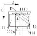
在一些实施例中,耦入段111在第一方向X上具有相对的入光侧111a与非入光侧111b,进入光学组件1的光能够从入光侧111a射入波导基体11中。在一些实施例中,耦出段113在第一方向X上具有相对的出光侧113a与非出光侧113b,进入光学组件1的光能够从出光侧113a射出光学组件1。In some embodiments, the
图7为本申请另一些实施例的光学组件1的剖视示意图,图7中虚线路径表示光的路径。FIG. 7 is a schematic cross-sectional view of an
如图7所示,在一些实施例中,耦入件12与耦出件13为一维光栅,使得射入光学组件1的光能够在耦入件12与耦出件13的影响下发生衍射,从而使得光能够在波导基体11内的传播并从耦出段113射出光学组件1。在本实施例中,可通过全息曝光或纳米压印等方式,将设计好的一维光栅图案转移到光刻胶上,再通过显影刻蚀等步骤将图案转移到波导基体11的材料表面以形成耦入件12或耦出件13。As shown in FIG. 7 , in some embodiments, the
图8为本申请又一些实施例的光学组件1的剖视示意图,图8中虚线路径表示光的路径。FIG. 8 is a schematic cross-sectional view of an
如图8所示,在一些实施例中,耦入件12与耦出件13为半透半反镜,耦入件12设置于非入光侧111b,使得射入光学组件1的光能够在耦入件12与耦出件13的影响下发生反射,从而使得光能够在波导基体11内的传播并从耦出段113射出光学组件1。As shown in FIG. 8 , in some embodiments, the
在一些实施例中,半透半反镜上用于反射光的外表面与第一方向X间具有预设角度,预设角度与波导基体11的全反射角间的关系可以满足:k<90°-j/2,其中,k为预设角度,j为全反射角,从而使得沿第一方向X射入耦入段111的光能够受耦入件12的反射后在波导基体11内发生全反射,并最终能够受耦出件13的反射后沿第一方向X射向达曼光栅14。In some embodiments, there is a preset angle between the outer surface of the half mirror for reflecting light and the first direction X, and the relationship between the preset angle and the total reflection angle of the
图9为本申请再一些实施例的光学组件1的剖视示意图,图10为本申请再一些实施例的光学组件1的剖视示意图,图9与图10中虚线路径表示光的路径。FIG. 9 is a schematic cross-sectional view of an
在一些实施例中,如图9所示,耦入件12为半透半反镜,耦出件13为一维光栅,耦入件12设置于非入光侧111b;或,如图10所示,耦入件12为一维光栅,耦出件13为半透半反镜。In some embodiments, as shown in FIG. 9 , the
在一些实施例中,当耦入件12与耦出件13其中一者为一维光栅另一者为半透半反镜时,光在一维光栅的衍射角度与半透半反镜的预设角度可以满足:i=180°-2k,其中,i为衍射角度,k为预设角度,从而使得沿第一方向X射入耦入段111的光能够受耦入件12的反射后在波导基体11内发生全反射,并最终能够受耦出件13的反射后沿第一方向X射向达曼光栅14。In some embodiments, when one of the coupling-in
图11为本申请一些实施例的光学组件1的局部剖视图,图12为本申请另一些实施例的光学组件1的局部剖视示意图,图11与图12中虚线路径表示光的路径。FIG. 11 is a partial cross-sectional view of an
在前述的任一实施例中,当耦入件12为一维光栅时,如图11所示,耦入件12可以为透射式一维光栅并设置于耦入段111的入光侧111a,使得光在透过耦入件12后能够产生传播方向的改变以从耦入段111中向波导段112传播。在前述的任一实施例中,当耦入件12为一维光栅时,如图12所示,耦入件12还可以为反射式一维光栅并设置于耦入段111的非入光侧111b,使得光从入光侧111a进入至耦入段111并射在耦入件12上后,光能够受耦入件12的影响而产生反射式衍射以改变传播方向,以使得光能够从耦入段111向波导段112传播。In any of the above-mentioned embodiments, when the
图13为本申请又一些实施例的光学组件1的局部剖视示意图,图13中虚线路径表示光的路径。FIG. 13 is a schematic partial cross-sectional view of an
如图13所示,在前述的任一实施例中,当耦出件13为一维光栅时,耦出件13可以为反射式一维光栅并设置于耦出段113的非出光侧113b,达曼光栅14可设置于耦出段113的出光侧113a,使得入射至耦出件13的光能够受耦入件12的影响而产生反射式衍射以改变传播方向,从而使得光能够朝向达曼光栅14进行传播并透过达曼光栅14最终射离光学组件1。As shown in FIG. 13 , in any of the aforementioned embodiments, when the
如图7至图13所示,在一些实施例中,光学组件1还包括主体部144,至少部分主体部144环绕波导段112设置,主体部144能够向波导基体11提供保护。通过设置主体部144的折射率小于波导基体11的折射率,使得光能够在波导段112内发生全反射后被传播至耦出段113。As shown in FIG. 7 to FIG. 13 , in some embodiments, the
在本实施例中,主体部144的折射率、波导基体11的折射率与波导基体11内的全反射角间的关系可以满足:j=arcsin(n2/n1),其中,j为全反射角,n1为波导基体11的折射率,n2为主体部144的折射率。In this embodiment, the relationship between the refractive index of the
在一些实施例中,主体部144的材料可以为折射率较低且透明度较高的材料,从而使得光学组件1具有较好的通透的外观。In some embodiments, the material of the
图14为本申请一些实施例的显示装置10的剖视示意图,图14中虚线路径表示光的路径。FIG. 14 is a schematic cross-sectional view of a
如图14所示,本申请还提供了一种显示装置10,显示装置10包括光源3以及如上述任一实施例中的光学组件1;光源3用于将光射入耦入段111或耦入件12。As shown in FIG. 14 , the present application also provides a
在一些实施例中,光源3可以为微型显示器,微型显示器可以用于显示出特定图像。In some embodiments, the light source 3 can be a microdisplay, and the microdisplay can be used to display specific images.
在本申请实施例中,显示装置10可以为AR(Augmented Reality,增强现实)眼镜、VR(Virtual Reality,虚拟现实)眼镜、全息显示设备、可穿戴式智能眼镜等显示装置10。其中,光学组件1可以用于接收并传递光源3发出的光,并使得穿过光学组件1的光具有较好的均匀性以显示到人眼中。In the embodiment of the present application, the
如图14所示,在一些实施例中,耦入段111在第一方向X上具有相对的入光侧111a与非入光侧111b,光源3设置于耦入段111的入光侧111a,光源3与光学组件1间设置有准直系统4,准直系统4用于改变光的传播方向,以使得光源3射出的光沿第一方向X传播至光学组件1,使得光能够较为集中的射入光学组件1并受耦入件12的影响以在波导基体11内发生全反射。As shown in FIG. 14 , in some embodiments, the
以上所述,仅为本申请的具体实施方式,所属领域的技术人员可以清楚地了解到,为了描述的方便和简洁,上述描述的系统、模块和单元的具体工作过程,可以参考前述方法实施例中的对应过程,在此不再赘述。应理解,本申请的保护范围并不局限于此,任何熟悉本技术领域的技术人员在本申请揭露的技术范围内,可轻易想到各种等效的修改或替换,这些修改或替换都应涵盖在本申请的保护范围之内。The above is only a specific implementation of the present application, and those skilled in the art can clearly understand that for the convenience and brevity of the description, the specific working process of the above-described systems, modules and units can refer to the foregoing method embodiments The corresponding process in , will not be repeated here. It should be understood that the protection scope of the present application is not limited thereto, and any person familiar with the technical field can easily think of various equivalent modifications or replacements within the technical scope disclosed in the application, and these modifications or replacements should cover all Within the protection scope of this application.
Claims (11)
Translated fromChinesePriority Applications (2)
| Application Number | Priority Date | Filing Date | Title |
|---|---|---|---|
| CN202310156485.2ACN116148970A (en) | 2023-02-22 | 2023-02-22 | Optical module and display device |
| PCT/CN2024/077504WO2024174952A1 (en) | 2023-02-22 | 2024-02-19 | Optical assembly and display apparatus |
Applications Claiming Priority (1)
| Application Number | Priority Date | Filing Date | Title |
|---|---|---|---|
| CN202310156485.2ACN116148970A (en) | 2023-02-22 | 2023-02-22 | Optical module and display device |
Publications (1)
| Publication Number | Publication Date |
|---|---|
| CN116148970Atrue CN116148970A (en) | 2023-05-23 |
Family
ID=86357971
Family Applications (1)
| Application Number | Title | Priority Date | Filing Date |
|---|---|---|---|
| CN202310156485.2APendingCN116148970A (en) | 2023-02-22 | 2023-02-22 | Optical module and display device |
Country Status (2)
| Country | Link |
|---|---|
| CN (1) | CN116148970A (en) |
| WO (1) | WO2024174952A1 (en) |
Cited By (1)
| Publication number | Priority date | Publication date | Assignee | Title |
|---|---|---|---|---|
| WO2024174952A1 (en)* | 2023-02-22 | 2024-08-29 | 维沃移动通信有限公司 | Optical assembly and display apparatus |
Family Cites Families (6)
| Publication number | Priority date | Publication date | Assignee | Title |
|---|---|---|---|---|
| JP2003014915A (en)* | 2001-07-03 | 2003-01-15 | Japan Science & Technology Corp | Optical element with Dammann-type grating |
| CN100492120C (en)* | 2005-12-16 | 2009-05-27 | 群康科技(深圳)有限公司 | Backlight module and its light guide plate |
| CN109696717A (en)* | 2019-03-07 | 2019-04-30 | 深圳珑璟光电技术有限公司 | A kind of diffraction grating and AR imaging device in more rectangular configuration periods |
| CN113703091B (en)* | 2021-08-25 | 2023-08-08 | 宁波舜宇奥来技术有限公司 | Optical waveguide system and near-eye display |
| CN218068458U (en)* | 2022-06-06 | 2022-12-16 | 深圳光峰科技股份有限公司 | Augmented reality device |
| CN116148970A (en)* | 2023-02-22 | 2023-05-23 | 维沃移动通信有限公司 | Optical module and display device |
- 2023
- 2023-02-22CNCN202310156485.2Apatent/CN116148970A/enactivePending
- 2024
- 2024-02-19WOPCT/CN2024/077504patent/WO2024174952A1/enactivePending
Cited By (1)
| Publication number | Priority date | Publication date | Assignee | Title |
|---|---|---|---|---|
| WO2024174952A1 (en)* | 2023-02-22 | 2024-08-29 | 维沃移动通信有限公司 | Optical assembly and display apparatus |
Also Published As
| Publication number | Publication date |
|---|---|
| WO2024174952A1 (en) | 2024-08-29 |
Similar Documents
| Publication | Publication Date | Title |
|---|---|---|
| KR102777539B1 (en) | Optical system including a light-guiding optical element having a partially reflective inner surface | |
| JP6507250B2 (en) | Lattice coupling type light guide | |
| CN112630969B (en) | A grating waveguide display device | |
| US11327236B2 (en) | Grating-coupled light guide, display system, and method employing optical concentration | |
| CN110764260A (en) | an augmented reality device | |
| CN212515221U (en) | Apparatus for presenting augmented reality image and system for implementing augmented reality display | |
| US20240402433A1 (en) | Diffractive optical waveguide and ar glasses | |
| US12374053B2 (en) | Apparatus for displaying augmented reality image, and system comprising apparatus | |
| CN111175971A (en) | A near-eye optical display system, augmented reality glasses | |
| CN111801526A (en) | Static multi-view display and method employing collimated guided light | |
| CN116507851A (en) | Slab waveguide and projector with intermode coupling | |
| CN111443486A (en) | Grating waveguide element and near-to-eye display device | |
| CN114063377A (en) | Waveguide-based projector | |
| CN107085264A (en) | A kind of planar optical waveguide | |
| CN112649963A (en) | Imaging module and augmented reality equipment | |
| CN116148970A (en) | Optical module and display device | |
| JP2024511586A (en) | Display structure and display device | |
| CN113933997A (en) | Near-eye display device based on dual-channel waveguide | |
| CN211577479U (en) | Hexagonal columnar structure for diffraction optical waveguide | |
| TW202143196A (en) | Animated static display and method | |
| CN214846067U (en) | Grating waveguide element and near-to-eye display equipment | |
| TW202030524A (en) | Static multiview display and method having multiview zones | |
| CN116931162A (en) | Diffraction optical waveguide and augmented reality display device | |
| CN115494574B (en) | An optical waveguide module and an AR display device | |
| US20220276489A1 (en) | Optical system and mixed reality device |
Legal Events
| Date | Code | Title | Description |
|---|---|---|---|
| PB01 | Publication | ||
| PB01 | Publication | ||
| SE01 | Entry into force of request for substantive examination | ||
| SE01 | Entry into force of request for substantive examination |